EP2055930A1 - Accumulator fuel injection device - Google Patents
Accumulator fuel injection device Download PDFInfo
- Publication number
- EP2055930A1 EP2055930A1 EP07791185A EP07791185A EP2055930A1 EP 2055930 A1 EP2055930 A1 EP 2055930A1 EP 07791185 A EP07791185 A EP 07791185A EP 07791185 A EP07791185 A EP 07791185A EP 2055930 A1 EP2055930 A1 EP 2055930A1
- Authority
- EP
- European Patent Office
- Prior art keywords
- accumulator
- armature
- pressure
- chamber
- fuel
- Prior art date
- Legal status (The legal status is an assumption and is not a legal conclusion. Google has not performed a legal analysis and makes no representation as to the accuracy of the status listed.)
- Granted
Links
Images


Classifications
-
- F—MECHANICAL ENGINEERING; LIGHTING; HEATING; WEAPONS; BLASTING
- F02—COMBUSTION ENGINES; HOT-GAS OR COMBUSTION-PRODUCT ENGINE PLANTS
- F02M—SUPPLYING COMBUSTION ENGINES IN GENERAL WITH COMBUSTIBLE MIXTURES OR CONSTITUENTS THEREOF
- F02M55/00—Fuel-injection apparatus characterised by their fuel conduits or their venting means; Arrangements of conduits between fuel tank and pump F02M37/00
- F02M55/02—Conduits between injection pumps and injectors, e.g. conduits between pump and common-rail or conduits between common-rail and injectors
- F02M55/025—Common rails
-
- F—MECHANICAL ENGINEERING; LIGHTING; HEATING; WEAPONS; BLASTING
- F02—COMBUSTION ENGINES; HOT-GAS OR COMBUSTION-PRODUCT ENGINE PLANTS
- F02M—SUPPLYING COMBUSTION ENGINES IN GENERAL WITH COMBUSTIBLE MIXTURES OR CONSTITUENTS THEREOF
- F02M55/00—Fuel-injection apparatus characterised by their fuel conduits or their venting means; Arrangements of conduits between fuel tank and pump F02M37/00
- F02M55/02—Conduits between injection pumps and injectors, e.g. conduits between pump and common-rail or conduits between common-rail and injectors
-
- F—MECHANICAL ENGINEERING; LIGHTING; HEATING; WEAPONS; BLASTING
- F02—COMBUSTION ENGINES; HOT-GAS OR COMBUSTION-PRODUCT ENGINE PLANTS
- F02M—SUPPLYING COMBUSTION ENGINES IN GENERAL WITH COMBUSTIBLE MIXTURES OR CONSTITUENTS THEREOF
- F02M47/00—Fuel-injection apparatus operated cyclically with fuel-injection valves actuated by fluid pressure
- F02M47/02—Fuel-injection apparatus operated cyclically with fuel-injection valves actuated by fluid pressure of accumulator-injector type, i.e. having fuel pressure of accumulator tending to open, and fuel pressure in other chamber tending to close, injection valves and having means for periodically releasing that closing pressure
-
- F—MECHANICAL ENGINEERING; LIGHTING; HEATING; WEAPONS; BLASTING
- F02—COMBUSTION ENGINES; HOT-GAS OR COMBUSTION-PRODUCT ENGINE PLANTS
- F02M—SUPPLYING COMBUSTION ENGINES IN GENERAL WITH COMBUSTIBLE MIXTURES OR CONSTITUENTS THEREOF
- F02M55/00—Fuel-injection apparatus characterised by their fuel conduits or their venting means; Arrangements of conduits between fuel tank and pump F02M37/00
- F02M55/04—Means for damping vibrations or pressure fluctuations in injection pump inlets or outlets
-
- F—MECHANICAL ENGINEERING; LIGHTING; HEATING; WEAPONS; BLASTING
- F02—COMBUSTION ENGINES; HOT-GAS OR COMBUSTION-PRODUCT ENGINE PLANTS
- F02M—SUPPLYING COMBUSTION ENGINES IN GENERAL WITH COMBUSTIBLE MIXTURES OR CONSTITUENTS THEREOF
- F02M63/00—Other fuel-injection apparatus having pertinent characteristics not provided for in groups F02M39/00 - F02M57/00 or F02M67/00; Details, component parts, or accessories of fuel-injection apparatus, not provided for in, or of interest apart from, the apparatus of groups F02M39/00 - F02M61/00 or F02M67/00; Combination of fuel pump with other devices, e.g. lubricating oil pump
- F02M63/0012—Valves
- F02M63/0014—Valves characterised by the valve actuating means
- F02M63/0015—Valves characterised by the valve actuating means electrical, e.g. using solenoid
-
- F—MECHANICAL ENGINEERING; LIGHTING; HEATING; WEAPONS; BLASTING
- F02—COMBUSTION ENGINES; HOT-GAS OR COMBUSTION-PRODUCT ENGINE PLANTS
- F02M—SUPPLYING COMBUSTION ENGINES IN GENERAL WITH COMBUSTIBLE MIXTURES OR CONSTITUENTS THEREOF
- F02M63/00—Other fuel-injection apparatus having pertinent characteristics not provided for in groups F02M39/00 - F02M57/00 or F02M67/00; Details, component parts, or accessories of fuel-injection apparatus, not provided for in, or of interest apart from, the apparatus of groups F02M39/00 - F02M61/00 or F02M67/00; Combination of fuel pump with other devices, e.g. lubricating oil pump
- F02M63/02—Fuel-injection apparatus having several injectors fed by a common pumping element, or having several pumping elements feeding a common injector; Fuel-injection apparatus having provisions for cutting-out pumps, pumping elements, or injectors; Fuel-injection apparatus having provisions for variably interconnecting pumping elements and injectors alternatively
- F02M63/0225—Fuel-injection apparatus having a common rail feeding several injectors ; Means for varying pressure in common rails; Pumps feeding common rails
- F02M63/023—Means for varying pressure in common rails
- F02M63/0235—Means for varying pressure in common rails by bleeding fuel pressure
- F02M63/025—Means for varying pressure in common rails by bleeding fuel pressure from the common rail
-
- F—MECHANICAL ENGINEERING; LIGHTING; HEATING; WEAPONS; BLASTING
- F02—COMBUSTION ENGINES; HOT-GAS OR COMBUSTION-PRODUCT ENGINE PLANTS
- F02M—SUPPLYING COMBUSTION ENGINES IN GENERAL WITH COMBUSTIBLE MIXTURES OR CONSTITUENTS THEREOF
- F02M69/00—Low-pressure fuel-injection apparatus ; Apparatus with both continuous and intermittent injection; Apparatus injecting different types of fuel
- F02M69/46—Details, component parts or accessories not provided for in, or of interest apart from, the apparatus covered by groups F02M69/02 - F02M69/44
- F02M69/54—Arrangement of fuel pressure regulators
-
- F—MECHANICAL ENGINEERING; LIGHTING; HEATING; WEAPONS; BLASTING
- F02—COMBUSTION ENGINES; HOT-GAS OR COMBUSTION-PRODUCT ENGINE PLANTS
- F02M—SUPPLYING COMBUSTION ENGINES IN GENERAL WITH COMBUSTIBLE MIXTURES OR CONSTITUENTS THEREOF
- F02M2200/00—Details of fuel-injection apparatus, not otherwise provided for
- F02M2200/31—Fuel-injection apparatus having hydraulic pressure fluctuations damping elements
- F02M2200/315—Fuel-injection apparatus having hydraulic pressure fluctuations damping elements for damping fuel pressure fluctuations
Definitions
- the present invention relates to an accumulator fuel injection device provided with a pressure control valve controlling a fuel pressure in the accumulator by moving an armature in an armature chamber and by adjusting escaped volumes of the fuel from the accumulator using a valving element formed integrally with the armature in a control chamber introducing the fuel in the accumulator.
- accumulator fuel injection devices of an engine comprising a supply pump, an accumulator storing highly-pressurized fuels pumped from the supply pump and an injector injecting the fuels supplied from the accumulator (for example, see JP2006-83821 ).
- These accumulator fuel injection devices were provided in the accumulator thereof with pressure sensors so as to detect the fuel pressures in the accumulator and solenoid valves so as to escape the fuels from the accumulator.
- the solenoid valves are constructed so that they can reduce the fuel pressures in the accumulator by moving the armature in an armature chamber and by adjusting escaped volumes of the fuels from the accumulator using a valving element formed integrally with an armature in a control chamber introducing the fuels in the accumulator.
- the switching of the solenoid valves are controlled based on detected values of the fuel pressures by the pressure sensors, thereby keeping the fuel pressures in the accumulator to the given pressures.
- the accumulator fuel injection device of the present invention comprises a means for attenuating a pressure transmitted from the accumulator to a valve seat, in the valve seat provided between the control chamber and the accumulator of the pressure control valve.
- the pressure attenuating means is constituted so as to provide an attenuating chamber in the valve seat, as well as an apertures on each of the side of the accumulator and the side of the control chamber in the attenuating chamber.
- the accumulator fuel injection device of the present invention comprises a means for equalizing the pressures of the control chamber and the armature chamber in the pressure control valve.
- the pressure equalizing means comprises continuous holes so as to communicate the control chamber with the armature chamber on each of the armature and a shaft formed integrally with the armature so as to exert on the valving element.
- the accumulator fuel injection device of the present invention which is provided with the pressure control valve controlling the fuel pressure in the accumulator by moving the armature in the armature chamber and by adjusting the escaped volumes of the fuel from the accumulator using the valving element formed integrally with the armature in the control chamber introducing the fuel in the accumulator
- the accumulator fuel injection device of the present invention comprises the means for attenuating the pressure transmitted from the accumulator to the valve seat, in the valve seat provided between the control chamber and the accumulator of the pressure control valve, so that the pressure fluctuation in the accumulator cannot be directly transmitted to the valve scat of the pressure control valve due to the pressure attenuating means, thereby reducing the pressure fluctuation of the valve seat so as to stabilize the operation of the pressure control valve.
- the pressure attenuating means is constituted so as to provide the attenuating chamber in the valve seat, as well as the apertures on each of the side of the accumulator and the side of the control chamber in the attenuating chamber, so that the pressure attenuating means can be formed with the simple structure, so as to restraining the production cost.
- the accumulator fuel injection device of the present invention which is provided with the pressure control valve controlling the fuel pressure in the accumulator by moving the armature in the armature chamber and by adjusting the escaped volumes of the fuel from the accumulator using the valving element formed integrally with the armature in the control chamber communicating with the accumulator
- the accumulator fuel injection device of the present invention comprises the means for equalizing the pressures of the control chamber and the armature chamber in the pressure control valve, so that the pressures exerting on each of the side end portion of the control chamber acting on the valving element of the armature and the side end portion of the armature chamber can be balanced out, thereby accurately controlling the valving element by the armature so as to stabilize the operation of the pressure control valve.
- the pressure equalizing means comprises continuous holes so as to communicate the control chamber with the armature chamber on each of the armature and the shaft formed integrally with the armature so as to exert on the valving element, so that the pressure attenuating means can be formed with the simple structure, so as to restrain the production cost.
- an accumulator fuel injection device of an engine comprises a supply pump 1, an accumulator 2, and plurality of injectors 3,3 ⁇ ⁇ ⁇ or the like.
- the accumulator fuel injection device pressurizes the fuel inhaled from a fuel tank 4 via a feed pump 5 by the supply pump 1 so as to pump it into the accumulator 2, and stores the highly-pressured fuels in the accumulator 2 so as to inject the fuels supplied from the accumulator 2 by the respective injectors 3 into a combustion chamber.
- the accumulator 2 includes a pressure control valve 6 controlling the fuel pressure in the accumulator 2, a switching of which results in escaping the fuels from the accumulator 2 to the fuel tank 4 so as to lower the fuel pressure in the accumulator 2.
- the accumulator 2 also includes a pressure sensor 7 for detecting the fuel pressure in the accumulator 2, which is connected to a controller 8 with the pressure control valve 6.
- the controller 8 controls the switching of the pressure control valve 6 based on the detected value of the fuel pressure by the pressure sensor 7 and adjusts the escaped volumes of the fuels so as to keep the fuel pressure in the accumulator 2 to the given pressure.
- the pressure control valve 6 is comprised of a solenoid valve and includes a valve seat 10 having a fuel passage 10a leading to the accumulator 2, a ball-like valving element 11 so as to close the fuel passage 10a of the valve seat 10, an armature 13 which can press the valving element 11 via a shaft 12, a spring 14 which biases in the direction where the armature 13 presses the valving element 11 on the valve seat 10 and a solenoid 15 which biases the armature 13 in the same direction as the biasing one of the spring 14 or the like, all of which are constructed as a valve holding member 16.
- valve holding member 16 In the pressure control valve 6, a part of the valve holding member 16 is inserted and fixed into one end of an accumulator body 2a, and the valve seat 10 is fitted onto the inner portion of the accumulator 2 of the valve holding member 16.
- the control chamber 21 is formed between the valve scat 10 and the valve holding member 16.
- the control chamber 21 is communicated with the accumulator 2 via the fuel passage 10a formed in the valve seat 10 and is connected to a fuel escaping passage 2b of the accumulator 2 via a fuel passage 16a formed in the valve holding member 16.
- the control chamber 21 is provided with the valving element 11, which can be pressed and attached to a sheet surface 10b so as to close the fuel passage 10a of the valve seat 10.
- the valve holding member 16 is incorporated at the outer portion of the accumulator 2 thereof into the solenoid 15, and is provided there with a cap 17 so as to cover the solenoid 15.
- An armature chamber 22 is formed in a cylindrical member 18 disposed on the inside of the solenoid 15 and the cap 17.
- the armature 13 is movably provided with the armature chamber 22.
- a spring support member 19 is is fixedly provided on the side of the cap 17 of the armature 13.
- the spring 14 is interposed between the armature 13 and the spring support member 19 so that the armature 13 is biased to the side of the accumulator 2 by a biasing force of the spring 14.
- the control chamber 21 of the valve holding member 16 and the armature chamber 22 are provided therebetween with a through-hole communicating them, and the shaft 12 is movable inserted into the through-hole with no space.
- the shaft 12 is projected on each of both ends thereof into the control chamber 21 and the armature chamber 22, one end of which is connected to the armature 13 in the armature chamber 22, so as to be integrally movable with the armature 13 and be biased to the side of the accumulator 2 by the biasing force of the spring 14.
- the shaft 12 is pressurized so as to contact on the other end thereof with the valving element 11 in the control chamber 21 and presses the valving element 11 to the side of the accumulator 2 with the armature 13 so as to be pressed and attached to the sheet surface 10b of the valve seat 10 and close the fuel passage 10a by the valving element 11.
- the solenoid 15 disposed around the armature chamber 22 is connected to the controller 8 with the pressure sensor 7 detecting the fuel pressure in the accumulator 2.
- the controller 8 changes the supply voltage (or the supply current) to the solenoid 15 based on the detected value of the fuel pressure detected by the pressure sensor 7 and biases the armature 13 in the same direction as the biasing one of the spring 14 so as to control opening degree of the fuel passage 10a by the valving element 11 pressing via the shaft 12 and adjust the fuel volumes passing through the fuel passage 10a.
- the armature 13 When the solenoid 15 is not energized, the armature 13 is biased to the side of the accumulator 2 by the biasing force of the spring 14,so that the fuel pressure in the accumulator 2 opening the fuel passage 10a is set up to be the predefined one. Meanwhile, when the solenoid 15 is energized, a force biasing in the same direction as the biasing one of the spring 14, i.e., the force increasing the predefined pressure of the spring 14 acts on the armature 13, depending on the largeness of exciting electrical power, and the armature 13 is also biased to the side of the accumulator 2, so that the fuel pressure in the accumulator 2 opening the fuel passage 10a is set up to be larger than the predefined one of the spring 14.
- the pressure control valve 6 is constituted so that the fuel pressure in the accumulator 2 can be kept to the given pressure, by controlling the largeness of exciting electrical power of the solenoid 15 using the controller 8.
- the given pressure of the spring 14 is set up in such a way that the fuel pressure in the accumulator 2 becomes a pressure that can inject the fuels, even if the solenoid 15 can not be energized due to the fault or the like.
- the pressure control valve 6 is constructed so that it can adjust the fuel flowing volumes of the fuel passage 10a, i.e., the fuel escaping volumes from the fuel escaping passage 2b of the accumulator 2, so as to control the fuel pressure in the accumulator 2, by biasing the armature 13 to the side of the accumulator 2 in the armature chamber 22 due to the spring 14 and the solenoid 15, as well as by controlling the opening degree of the fuel passage 10a by the valving element 11 pressing via the shaft 12 by the armature 13 in the control chamber 21.
- the pressure control means 6 includes a means for attenuating the pressure transmitted from the accumulator 2 to the valve seat 10 in the valve seat 10, and a means for equalizing the pressures of the control chamber 21 and the armature chamber 22.
- the pressure attenuating means includes an attenuating chamber 30 on the side of the accumulator 2 relative to the sheet surface 10b.
- the pressure attenuating means also includes a first aperture 31 between the attenuating chamber 30 and the accumulator 2, as well as a second aperture between the attenuating chamber 30 and the control chamber 21, those of which are constituted as the fuel passage 10a communicating the accumulator 2 with the control chamber 21.
- the attenuating chamber 30 is comprised of a large diameter portion of the fuel passage 10a in the valve scat 10 and an aperture forming member 35 inserted and fixed into the large diameter portion from the side of the accumulator 2, which is disposed on the approximately middle portion (in the axial direction) of the fuel passage 10a.
- the first aperture 31 is made up of a small diameter bore formed in the aperture forming member 35, at one end of which is connected to the fuel inflowing side of the attenuating chamber 30, and at the other end of which is connected to the accumulator 2.
- the second aperture 32 is made up of a small diameter portion of the fuel passage 10a in the valve seat 10, at one end of which is connected to the fuel discharging side of the attenuating chamber 30, and at the other end of which is connected to the control chamber 21.
- the pressure attenuating means is not limited to the above-mentioned construction, it may be provided with the attenuating chamber or the aperture in the valve seat 10 without the aperture forming member 35 or alternatively may be provided with an orifice instead of them.
- the pressure control valve 6 controlling the fuel pressure in the accumulator 2 by moving the armature 13 in the armature chamber 22 and by adjusting the escaped volumes of the fuels from the accumulator 2 due to the valving element 11 comprised integral with the armature 13 in the control chamber 21 introducing the fuels in the accumulator 2, because the valve seat 10,which is disposed between the control chamber 21 of the pressure control valve 6 and the accumulator 2, is provided with the means for attenuating the pressure transmitted from the accumulator 2 to the valve seat 10, the pressure fluctuation in the accumulator 2 can not be directly transmitted to the valve seat 10 of the pressure control valve 6 due to the pressure attenuating means, thereby minifying the pressure fluctuation of the valve seat 10 so as to stabilize the operation of the pressure control valve 6.
- the pressure attenuating means is constructed so that it includes the attenuating chamber 30 in the valve seat 10 and the respective apertures 31, 32 on each of the side of the accumulator 2 and the side of the control chamber 21 of the attenuating chamber 30, respectively, whereby the pressure attenuating means can be constituted with the simple structures so as to restrain the production cost.
- the pressure equalizing means is constructed in such a way that the shaft 12 extended from the armature chamber 22 to the control chamber 21 is provided with the first continuous hole 12a, and the armature 13 connected to the shaft 12 in the armature chamber 22 is provided with the second continuous hole 13a, as well as the first continuous hole 12a and the second continuous hole 13a are communicated with each other.
- the first continuous hole 12a includes a longitudinal continuous hole 41 extended in the direction perpendicular to the axial direction of the shaft 12 and a horizontal continuous hole 42 extended in the axial direction of the shaft 12.
- the longitudinal continuous hole 41 is extended to the outer peripheral surface of the shaft 12 so as to reach the control chamber 21, and the horizontal continuous hole 42 communicating with the longitudinal continuous hole 41 is extended to the inside of the armature 13 so as to communicate with the second continuous hole 13a.
- the second continuous hole 13a is comprised of a longitudinal continuous hole 43 extending in the direction perpendicular to the axial direction of the armature 13 and a horizontal continuous hole 44 extending in the axial direction of the armature 13.
- the longitudinal continuous hole 43 communicating with the first continuous hole 12a is extended to the outer peripheral surface of the armature 13 so as to communicating with the horizontal continuous hole 44
- the horizontal continuous hole 44 is extended to the respective ends of the accumulator 2 side and the cap 17 side of the armature 13 so as to reach the armature chamber 22.
- the horizontal continuous hole 44 includes a chase extended in the axial direction on the outer peripheral portion of the armature 13 and the cylindrical member 18 that incorporates the armature 13 with no space.
- control chamber 21 is communicated with the armature chamber 22 via the first continuous hole 12a of the shaft 12 and the second continuous hole 13a of the armature 13, so as to be equalize the pressures of the control chamber 21 and the armature chamber 22, so that the pressures , which are acting on each of the end portion of the control chamber 21 side of the shaft 12 and the end portion of to the armature chamber 22 side of the armature 13, are balanced out.
- the second continuous hole 13a provided with the armature 13 is not limited to the above-described construction, and it may be formed so as to penetrate the armature 13, and especially when the horizontal continuous hole 42 of the first continuous hole 12a is provided so as to be extended, it may be comprised only of the horizontal continuous hole 44 without the longitudinal continuous hole 43.
- the pressure control valve 6 controlling the fuel pressure in the accumulator 2 by moving the armature 13 in the armature chamber 22 and by adjusting the escaped volumes of the fuels from the accumulator 2 due to the valving element 11 comprised integral with the armature 13 in the control chamber 21 communicating with the accumulator 2, because the pressure control valve 6 is provided with the means for equalizing the pressures of the control chamber 21 and the armature chamber 22, the pressures acting on each of the end portions of the control chamber 21 side acting on the valving element 11 and the armature chamber 22 side in the armature 13, i.e., the pressures, which are acting on each of the end portion of the control chamber 21 side of the armature 13 and the end portion of the control chamber 21 side of the shaft 12 comprised integral with the armature 13, can be balanced out, thereby accurately controlling the valving element 11 by the armature 13 so as to stabilize the operation of the pressure control valve 6.
- the pressure equalizing means includes the respective continuous holes 13a, 12a communicating the control chamber 21 with the armature chamber 22 in each of the armature 13 and the shaft 12 comprised integral with the armature 13 so as to act on the valving element 11, so that the pressure equalizing means can be constituted using the simple structures so as to restrain the production cost.
- the accumulator fuel injection device of the present invention is applicable in that it can stabilize the operation of the pressure control valve controlling the fuel pressure in the accumulator.
Landscapes
- Engineering & Computer Science (AREA)
- Chemical & Material Sciences (AREA)
- Combustion & Propulsion (AREA)
- Mechanical Engineering (AREA)
- General Engineering & Computer Science (AREA)
- Physics & Mathematics (AREA)
- Fluid Mechanics (AREA)
- Fuel-Injection Apparatus (AREA)
Abstract
Description
- The present invention relates to an accumulator fuel injection device provided with a pressure control valve controlling a fuel pressure in the accumulator by moving an armature in an armature chamber and by adjusting escaped volumes of the fuel from the accumulator using a valving element formed integrally with the armature in a control chamber introducing the fuel in the accumulator.
- Conventionally, there are well-known accumulator fuel injection devices of an engine, comprising a supply pump, an accumulator storing highly-pressurized fuels pumped from the supply pump and an injector injecting the fuels supplied from the accumulator (for example, see
JP2006-83821 - The solenoid valves are constructed so that they can reduce the fuel pressures in the accumulator by moving the armature in an armature chamber and by adjusting escaped volumes of the fuels from the accumulator using a valving element formed integrally with an armature in a control chamber introducing the fuels in the accumulator. The switching of the solenoid valves are controlled based on detected values of the fuel pressures by the pressure sensors, thereby keeping the fuel pressures in the accumulator to the given pressures.
- However, in the conventional accumulator fuel injection devices, when the pressures in the accumulator are largely varied, they are approximately directly transmitted from the accumulator to the pressure control valves, thereby largely varying pressures of valve seats of the pressure control valves. The pressures of the control chamber and the armature chamber are not equalized in the pressure control valve, so that sometimes the valving element was not accurately controlled using the armature. Accordingly, the operation of the pressure control valve were unstable.
- In an accumulator fuel injection device provided with a pressure control valve controlling a fuel pressure in an accumulator by moving the armature in an armature chamber and by adjusting escaped volumes of the fuel from the accumulator using a valving element formed integrally with an armature in a control chamber introducing the fuel in the accumulator, the accumulator fuel injection device of the present invention comprises a means for attenuating a pressure transmitted from the accumulator to a valve seat, in the valve seat provided between the control chamber and the accumulator of the pressure control valve.
- In the accumulator fuel injection device of the present invention, the pressure attenuating means is constituted so as to provide an attenuating chamber in the valve seat, as well as an apertures on each of the side of the accumulator and the side of the control chamber in the attenuating chamber.
- In an accumulator fuel injection device provided with a pressure control valve controlling a fuel pressure in an accumulator by moving the armature in an armature chamber and by adjusting escaped volumes of the fuel from the accumulator using a valving element formed integrally with an armature in a control chamber communicating with the accumulator, the accumulator fuel injection device of the present invention comprises a means for equalizing the pressures of the control chamber and the armature chamber in the pressure control valve.
- In the accumulator fuel injection device of the present invention, the pressure equalizing means comprises continuous holes so as to communicate the control chamber with the armature chamber on each of the armature and a shaft formed integrally with the armature so as to exert on the valving element.
- In the accumulator fuel injection device of the present invention, which is provided with the pressure control valve controlling the fuel pressure in the accumulator by moving the armature in the armature chamber and by adjusting the escaped volumes of the fuel from the accumulator using the valving element formed integrally with the armature in the control chamber introducing the fuel in the accumulator, the accumulator fuel injection device of the present invention comprises the means for attenuating the pressure transmitted from the accumulator to the valve seat, in the valve seat provided between the control chamber and the accumulator of the pressure control valve, so that the pressure fluctuation in the accumulator cannot be directly transmitted to the valve scat of the pressure control valve due to the pressure attenuating means, thereby reducing the pressure fluctuation of the valve seat so as to stabilize the operation of the pressure control valve.
- In the accumulator fuel injection device of the present invention, the pressure attenuating means is constituted so as to provide the attenuating chamber in the valve seat, as well as the apertures on each of the side of the accumulator and the side of the control chamber in the attenuating chamber, so that the pressure attenuating means can be formed with the simple structure, so as to restraining the production cost.
- In the accumulator fuel injection device of the present invention, which is provided with the pressure control valve controlling the fuel pressure in the accumulator by moving the armature in the armature chamber and by adjusting the escaped volumes of the fuel from the accumulator using the valving element formed integrally with the armature in the control chamber communicating with the accumulator, the accumulator fuel injection device of the present invention comprises the means for equalizing the pressures of the control chamber and the armature chamber in the pressure control valve, so that the pressures exerting on each of the side end portion of the control chamber acting on the valving element of the armature and the side end portion of the armature chamber can be balanced out, thereby accurately controlling the valving element by the armature so as to stabilize the operation of the pressure control valve.
- In the accumulator fuel injection device of the present invention, the pressure equalizing means comprises continuous holes so as to communicate the control chamber with the armature chamber on each of the armature and the shaft formed integrally with the armature so as to exert on the valving element, so that the pressure attenuating means can be formed with the simple structure, so as to restrain the production cost.
-
-
Fig. 1 is a diagram of an entire construction of an accumulator fuel injection device according to an embodiment of the present invention. -
Fig. 2 is a cross-sectional view of a pressure control valve. -
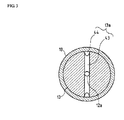
Fig. 3 is a cross-sectional view of an armature portion along the line X-X inFig. 2 . -
- 2
- accumulator
- 6
- pressure control valve
- 10
- valve seat
- 11
- valving element
- 12
- shaft
- 12a
- continuous hole
- 13
- armature
- 13a
- continuous hole
- 21
- control chamber
- 22
- armature chamber
- 30
- attenuating chamber
- 31
- aperture
- 32
- aperture
- As shown in
Fig. 1 , an accumulator fuel injection device of an engine comprises a supply pump 1, an accumulator 2, and plurality of injectors 3,3 · · · or the like. The accumulator fuel injection device pressurizes the fuel inhaled from a fuel tank 4 via a feed pump 5 by the supply pump 1 so as to pump it into the accumulator 2, and stores the highly-pressured fuels in the accumulator 2 so as to inject the fuels supplied from the accumulator 2 by the respective injectors 3 into a combustion chamber. - The accumulator 2 includes a pressure control valve 6 controlling the fuel pressure in the accumulator 2, a switching of which results in escaping the fuels from the accumulator 2 to the fuel tank 4 so as to lower the fuel pressure in the accumulator 2. The accumulator 2 also includes a
pressure sensor 7 for detecting the fuel pressure in the accumulator 2, which is connected to acontroller 8 with the pressure control valve 6. Thecontroller 8 controls the switching of the pressure control valve 6 based on the detected value of the fuel pressure by thepressure sensor 7 and adjusts the escaped volumes of the fuels so as to keep the fuel pressure in the accumulator 2 to the given pressure. - As shown in
Fig. 2 , the pressure control valve 6 is comprised of a solenoid valve and includes avalve seat 10 having afuel passage 10a leading to the accumulator 2, a ball-like valving element 11 so as to close thefuel passage 10a of thevalve seat 10, anarmature 13 which can press the valving element 11 via ashaft 12,aspring 14 which biases in the direction where thearmature 13 presses the valving element 11 on thevalve seat 10 and asolenoid 15 which biases thearmature 13 in the same direction as the biasing one of thespring 14 or the like, all of which are constructed as a valve holding member 16. - In the pressure control valve 6, a part of the valve holding member 16 is inserted and fixed into one end of an accumulator body 2a, and the
valve seat 10 is fitted onto the inner portion of the accumulator 2 of the valve holding member 16. Thecontrol chamber 21 is formed between thevalve scat 10 and the valve holding member 16. Thecontrol chamber 21 is communicated with the accumulator 2 via thefuel passage 10a formed in thevalve seat 10 and is connected to afuel escaping passage 2b of the accumulator 2 via afuel passage 16a formed in the valve holding member 16. Thecontrol chamber 21 is provided with the valving element 11, which can be pressed and attached to asheet surface 10b so as to close thefuel passage 10a of thevalve seat 10. - The valve holding member 16 is incorporated at the outer portion of the accumulator 2 thereof into the
solenoid 15, and is provided there with acap 17 so as to cover thesolenoid 15. Anarmature chamber 22 is formed in acylindrical member 18 disposed on the inside of thesolenoid 15 and thecap 17. Thearmature 13 is movably provided with thearmature chamber 22. Aspring support member 19 is is fixedly provided on the side of thecap 17 of thearmature 13. Thespring 14 is interposed between thearmature 13 and thespring support member 19 so that thearmature 13 is biased to the side of the accumulator 2 by a biasing force of thespring 14. - The
control chamber 21 of the valve holding member 16 and thearmature chamber 22 are provided therebetween with a through-hole communicating them, and theshaft 12 is movable inserted into the through-hole with no space. Theshaft 12 is projected on each of both ends thereof into thecontrol chamber 21 and thearmature chamber 22, one end of which is connected to thearmature 13 in thearmature chamber 22, so as to be integrally movable with thearmature 13 and be biased to the side of the accumulator 2 by the biasing force of thespring 14. Theshaft 12 is pressurized so as to contact on the other end thereof with the valving element 11 in thecontrol chamber 21 and presses the valving element 11 to the side of the accumulator 2 with thearmature 13 so as to be pressed and attached to thesheet surface 10b of thevalve seat 10 and close thefuel passage 10a by the valving element 11. - The
solenoid 15 disposed around thearmature chamber 22 is connected to thecontroller 8 with thepressure sensor 7 detecting the fuel pressure in the accumulator 2. Thecontroller 8 changes the supply voltage (or the supply current) to thesolenoid 15 based on the detected value of the fuel pressure detected by thepressure sensor 7 and biases thearmature 13 in the same direction as the biasing one of thespring 14 so as to control opening degree of thefuel passage 10a by the valving element 11 pressing via theshaft 12 and adjust the fuel volumes passing through thefuel passage 10a. - When the
solenoid 15 is not energized, thearmature 13 is biased to the side of the accumulator 2 by the biasing force of thespring 14,so that the fuel pressure in the accumulator 2 opening thefuel passage 10a is set up to be the predefined one. Meanwhile, when thesolenoid 15 is energized, a force biasing in the same direction as the biasing one of thespring 14, i.e., the force increasing the predefined pressure of thespring 14 acts on thearmature 13, depending on the largeness of exciting electrical power, and thearmature 13 is also biased to the side of the accumulator 2, so that the fuel pressure in the accumulator 2 opening thefuel passage 10a is set up to be larger than the predefined one of thespring 14. Thus, the pressure control valve 6 is constituted so that the fuel pressure in the accumulator 2 can be kept to the given pressure, by controlling the largeness of exciting electrical power of thesolenoid 15 using thecontroller 8. Incidentally, the given pressure of thespring 14 is set up in such a way that the fuel pressure in the accumulator 2 becomes a pressure that can inject the fuels, even if thesolenoid 15 can not be energized due to the fault or the like. - As described above, the pressure control valve 6 is constructed so that it can adjust the fuel flowing volumes of the
fuel passage 10a, i.e., the fuel escaping volumes from thefuel escaping passage 2b of the accumulator 2, so as to control the fuel pressure in the accumulator 2, by biasing thearmature 13 to the side of the accumulator 2 in thearmature chamber 22 due to thespring 14 and thesolenoid 15, as well as by controlling the opening degree of thefuel passage 10a by the valving element 11 pressing via theshaft 12 by thearmature 13 in thecontrol chamber 21. The pressure control means 6includes a means for attenuating the pressure transmitted from the accumulator 2 to thevalve seat 10 in thevalve seat 10, and a means for equalizing the pressures of thecontrol chamber 21 and thearmature chamber 22. - For example, as shown in
Fig. 2 , the pressure attenuating means includes an attenuatingchamber 30 on the side of the accumulator 2 relative to thesheet surface 10b. The pressure attenuating means also includes afirst aperture 31 between the attenuatingchamber 30 and the accumulator 2, as well as a second aperture between the attenuatingchamber 30 and thecontrol chamber 21, those of which are constituted as thefuel passage 10a communicating the accumulator 2 with thecontrol chamber 21. The attenuatingchamber 30 is comprised of a large diameter portion of thefuel passage 10a in thevalve scat 10 and anaperture forming member 35 inserted and fixed into the large diameter portion from the side of the accumulator 2, which is disposed on the approximately middle portion (in the axial direction) of thefuel passage 10a. - The
first aperture 31 is made up of a small diameter bore formed in theaperture forming member 35, at one end of which is connected to the fuel inflowing side of the attenuatingchamber 30, and at the other end of which is connected to the accumulator 2. Thesecond aperture 32 is made up of a small diameter portion of thefuel passage 10a in thevalve seat 10, at one end of which is connected to the fuel discharging side of the attenuatingchamber 30, and at the other end of which is connected to thecontrol chamber 21. When the fuels pass through thefuel passage 10a, they are set up to be introduced from the accumulator 2, via thefirst aperture 31, the attenuatingchamber 30 and thesecond aperture 32 in this order, to thecontrol chamber 21. - Thus, while the pressure is transmitted from the accumulator 2 to the
valve seat 10 of the pressure control valve 6, it is attenuated through the attenuatingchamber 30 and theapertures valve seat 10. In this regard, the pressure attenuating means is not limited to the above-mentioned construction, it may be provided with the attenuating chamber or the aperture in thevalve seat 10 without theaperture forming member 35 or alternatively may be provided with an orifice instead of them. - As seen from the above, in the accumulator fuel injection device equipped with the pressure control valve 6 controlling the fuel pressure in the accumulator 2 by moving the
armature 13 in thearmature chamber 22 and by adjusting the escaped volumes of the fuels from the accumulator 2 due to the valving element 11 comprised integral with thearmature 13 in thecontrol chamber 21 introducing the fuels in the accumulator 2, because thevalve seat 10,which is disposed between thecontrol chamber 21 of the pressure control valve 6 and the accumulator 2, is provided with the means for attenuating the pressure transmitted from the accumulator 2 to thevalve seat 10, the pressure fluctuation in the accumulator 2 can not be directly transmitted to thevalve seat 10 of the pressure control valve 6 due to the pressure attenuating means, thereby minifying the pressure fluctuation of thevalve seat 10 so as to stabilize the operation of the pressure control valve 6. - In the accumulator fuel injection device, the pressure attenuating means is constructed so that it includes the attenuating
chamber 30 in thevalve seat 10 and therespective apertures control chamber 21 of the attenuatingchamber 30, respectively, whereby the pressure attenuating means can be constituted with the simple structures so as to restrain the production cost. - Also, for example, as shown in
Fig, 2 , the pressure equalizing means, is constructed in such a way that theshaft 12 extended from thearmature chamber 22 to thecontrol chamber 21 is provided with the firstcontinuous hole 12a, and thearmature 13 connected to theshaft 12 in thearmature chamber 22 is provided with the secondcontinuous hole 13a, as well as the firstcontinuous hole 12a and the secondcontinuous hole 13a are communicated with each other. The firstcontinuous hole 12a includes a longitudinalcontinuous hole 41 extended in the direction perpendicular to the axial direction of theshaft 12 and a horizontalcontinuous hole 42 extended in the axial direction of theshaft 12. The longitudinalcontinuous hole 41 is extended to the outer peripheral surface of theshaft 12 so as to reach thecontrol chamber 21, and the horizontalcontinuous hole 42 communicating with the longitudinalcontinuous hole 41 is extended to the inside of thearmature 13 so as to communicate with the secondcontinuous hole 13a. - The second
continuous hole 13a is comprised of a longitudinalcontinuous hole 43 extending in the direction perpendicular to the axial direction of thearmature 13 and a horizontalcontinuous hole 44 extending in the axial direction of thearmature 13. The longitudinalcontinuous hole 43 communicating with the firstcontinuous hole 12a is extended to the outer peripheral surface of thearmature 13 so as to communicating with the horizontalcontinuous hole 44, and the horizontalcontinuous hole 44 is extended to the respective ends of the accumulator 2 side and thecap 17 side of thearmature 13 so as to reach thearmature chamber 22. In this regard, as shown inFig. 3 , the horizontalcontinuous hole 44 includes a chase extended in the axial direction on the outer peripheral portion of thearmature 13 and thecylindrical member 18 that incorporates thearmature 13 with no space. - In this way, the
control chamber 21 is communicated with thearmature chamber 22 via the firstcontinuous hole 12a of theshaft 12 and the secondcontinuous hole 13a of thearmature 13, so as to be equalize the pressures of thecontrol chamber 21 and thearmature chamber 22, so that the pressures , which are acting on each of the end portion of thecontrol chamber 21 side of theshaft 12 and the end portion of to thearmature chamber 22 side of thearmature 13, are balanced out. Incidentally the secondcontinuous hole 13a provided with thearmature 13 is not limited to the above-described construction, and it may be formed so as to penetrate thearmature 13, and especially when the horizontalcontinuous hole 42 of the firstcontinuous hole 12a is provided so as to be extended, it may be comprised only of the horizontalcontinuous hole 44 without the longitudinalcontinuous hole 43. - As seen from the above, in the accumulator fuel injection device equipped with the pressure control valve 6 controlling the fuel pressure in the accumulator 2 by moving the
armature 13 in thearmature chamber 22 and by adjusting the escaped volumes of the fuels from the accumulator 2 due to the valving element 11 comprised integral with thearmature 13 in thecontrol chamber 21 communicating with the accumulator 2, because the pressure control valve 6 is provided with the means for equalizing the pressures of thecontrol chamber 21 and thearmature chamber 22, the pressures acting on each of the end portions of thecontrol chamber 21 side acting on the valving element 11 and thearmature chamber 22 side in thearmature 13, i.e., the pressures, which are acting on each of the end portion of thecontrol chamber 21 side of thearmature 13 and the end portion of thecontrol chamber 21 side of theshaft 12 comprised integral with thearmature 13, can be balanced out, thereby accurately controlling the valving element 11 by thearmature 13 so as to stabilize the operation of the pressure control valve 6. - In the accumulator fuel injection device, the pressure equalizing means includes the respective
continuous holes control chamber 21 with thearmature chamber 22 in each of thearmature 13 and theshaft 12 comprised integral with thearmature 13 so as to act on the valving element 11, so that the pressure equalizing means can be constituted using the simple structures so as to restrain the production cost. - The accumulator fuel injection device of the present invention is applicable in that it can stabilize the operation of the pressure control valve controlling the fuel pressure in the accumulator.
Claims (4)
- An accumulator fuel injection device comprising:a pressure control valve, the pressure control valve controlling a fuel pressure in an accumulator by moving an armature in an armature chamber and by adjusting an escaped volume of the fuel from the accumulator using a valving element formed integrally with the armature in a control chamber introducing the fuel in the accumulator,wherein a means for attenuating a pressure transmitted from the accumulator to a valve seat is provided, in the valve seat provided between the control chamber and the accumulator of the pressure control valve.
- The accumulator fuel injection device as set forth in claim 1, wherein, the pressure attenuating means is constituted so as to provide an attenuating chamber in the valve seat, as well as apertures on each of the side of the accumulator and the side of the control chamber.
- An accumulator fuel injection device as comprising:a pressure control valve, the pressure control valve controlling a fuel pressure in an accumulator by moving an armature in an armature chamber and by adjusting an escaped volume of the fuel from the accumulator using a valving element formed integrally with the armature in a control chamber communicating with the accumulator,wherein a means for equalizing pressures of the control chamber and the armature chamber is provided in the pressure control valve.
- The accumulator fuel injection device as set forth in claim 3, wherein, the pressure equalizing means includes continuous holes so as to communicate each of the control chamber and the armature chamber on each of the armature and a shaft formed integrally with the armature so as to exert on the valving element.
Applications Claiming Priority (2)
| Application Number | Priority Date | Filing Date | Title |
|---|---|---|---|
| JP2006222084A JP2008045486A (en) | 2006-08-16 | 2006-08-16 | Accumulator fuel injection device |
| PCT/JP2007/064453 WO2008020530A1 (en) | 2006-08-16 | 2007-07-23 | Accumulator fuel injection device |
Publications (3)
| Publication Number | Publication Date |
|---|---|
| EP2055930A1 true EP2055930A1 (en) | 2009-05-06 |
| EP2055930A4 EP2055930A4 (en) | 2011-09-07 |
| EP2055930B1 EP2055930B1 (en) | 2013-09-11 |
Family
ID=39082057
Family Applications (1)
| Application Number | Title | Priority Date | Filing Date |
|---|---|---|---|
| EP07791185.7A Not-in-force EP2055930B1 (en) | 2006-08-16 | 2007-07-23 | Pressure control valve |
Country Status (6)
| Country | Link |
|---|---|
| US (1) | US7921827B2 (en) |
| EP (1) | EP2055930B1 (en) |
| JP (1) | JP2008045486A (en) |
| KR (1) | KR101031477B1 (en) |
| CN (1) | CN101517222B (en) |
| WO (1) | WO2008020530A1 (en) |
Families Citing this family (5)
| Publication number | Priority date | Publication date | Assignee | Title |
|---|---|---|---|---|
| DE102009047649A1 (en) * | 2009-12-08 | 2011-06-09 | Robert Bosch Gmbh | Pressure control valve for regulating the pressure in a high pressure fuel accumulator of an internal combustion engine |
| US9297194B2 (en) * | 2010-04-01 | 2016-03-29 | Dorma Deutschland Gmbh | Hydraulic solenoid distribution valve |
| JP5628121B2 (en) * | 2011-09-20 | 2014-11-19 | 日立オートモティブシステムズ株式会社 | High pressure fuel supply pump |
| EP2667012B1 (en) * | 2012-05-25 | 2017-02-22 | Caterpillar Motoren GmbH & Co. KG | Baffle body with a wear resistant insert element and baffle body for a plunger operated fuel pump |
| JP6224415B2 (en) * | 2013-10-29 | 2017-11-01 | 日立オートモティブシステムズ株式会社 | High pressure fuel supply pump |
Family Cites Families (26)
| Publication number | Priority date | Publication date | Assignee | Title |
|---|---|---|---|---|
| IT208326Z2 (en) * | 1986-11-07 | 1988-05-28 | Altecna Azienda Della Weber S | PRESSURE REGULATING SOLENOID VALVE PARTICULARLY FOR HIGH PRESSURE CIRCUITS OF FUEL INJECTION SYSTEMS FOR INTERNAL COMBUSTION ENGINES |
| US5174334A (en) * | 1988-04-29 | 1992-12-29 | Chrysler Corporation | Noise control device for a solenoid-actuated valve |
| JPH0823947B2 (en) | 1989-09-14 | 1996-03-06 | シャープ株式会社 | Double cassette tape recorder |
| JPH03102668U (en) * | 1990-02-07 | 1991-10-25 | ||
| DE4142998C1 (en) * | 1991-12-24 | 1993-07-22 | Robert Bosch Gmbh, 7000 Stuttgart, De | |
| JP2588365Y2 (en) * | 1992-06-23 | 1999-01-06 | 株式会社ユニシアジェックス | Pressure control valve |
| US5651501A (en) * | 1993-12-23 | 1997-07-29 | Caterpillar Inc. | Fluid damping of a valve assembly |
| JP3465407B2 (en) * | 1994-07-29 | 2003-11-10 | アイシン精機株式会社 | On-off solenoid valve |
| JPH0872687A (en) * | 1994-09-01 | 1996-03-19 | Sumitomo Electric Ind Ltd | Brake system equipment |
| JPH08261102A (en) * | 1995-03-28 | 1996-10-08 | Toyoda Gosei Co Ltd | Fuel pressure pulsation damping device |
| DE19708104A1 (en) * | 1997-02-28 | 1998-09-03 | Bosch Gmbh Robert | magnetic valve |
| US5984259A (en) * | 1997-11-26 | 1999-11-16 | Saturn Electronics & Engineering, Inc. | Proportional variable force solenoid control valve with armature damping |
| DE19855667A1 (en) * | 1997-12-05 | 1999-08-26 | Denso Corp | Magnetic valve for vehicle braking system |
| DE19820341C2 (en) * | 1998-05-07 | 2000-04-06 | Daimler Chrysler Ag | Actuator for a high pressure injector for liquid injection media |
| EP1155233B1 (en) * | 1999-02-24 | 2005-01-19 | Siemens Aktiengesellschaft | Regulating mechanism for controlling increasing pressure of fuel for a fuel injector |
| JP3782252B2 (en) * | 1999-04-01 | 2006-06-07 | 三菱電機株式会社 | Method and apparatus for controlling fuel pressure regulating valve |
| DE19952774B4 (en) * | 1999-11-03 | 2004-03-11 | Daimlerchrysler Ag | Device for draining fluid from a system |
| DE10061188A1 (en) * | 2000-12-08 | 2002-07-11 | Knf Flodos Ag Sursee | pulsation dampers |
| ITTO20001227A1 (en) * | 2000-12-29 | 2002-06-29 | Fiat Ricerche | COMMON MANIFOLD INJECTION SYSTEM FOR AN INTERNAL COMBUSTION ENGINE, WITH A FUEL PRE-DOSING DEVICE. |
| US20020117216A1 (en) * | 2001-02-28 | 2002-08-29 | Eaton Corporation | Solenoid operated valve with hydraulic dampening |
| US6810909B2 (en) * | 2002-08-08 | 2004-11-02 | Eaton Corporation | Solenoid operated pressure control valve |
| JP3102668U (en) * | 2004-01-06 | 2004-07-15 | 郭信志 | Auxiliary training machine |
| JP4355640B2 (en) | 2004-09-17 | 2009-11-04 | ヤンマー株式会社 | Fuel injection device |
| JP4634285B2 (en) * | 2005-02-24 | 2011-02-16 | 三菱重工業株式会社 | Electromagnetic control fuel injection device with poppet valve |
| US7334770B2 (en) * | 2005-08-22 | 2008-02-26 | Wei-Ching Wang | Solenoid isolation valve |
| US7766040B2 (en) * | 2007-03-13 | 2010-08-03 | Eaton Corporation | Pressure control valve assembly |
-
2006
- 2006-08-16 JP JP2006222084A patent/JP2008045486A/en active Pending
-
2007
- 2007-07-23 CN CN2007800346065A patent/CN101517222B/en not_active Expired - Fee Related
- 2007-07-23 WO PCT/JP2007/064453 patent/WO2008020530A1/en not_active Ceased
- 2007-07-23 KR KR1020097005370A patent/KR101031477B1/en not_active Expired - Fee Related
- 2007-07-23 US US12/377,477 patent/US7921827B2/en not_active Expired - Fee Related
- 2007-07-23 EP EP07791185.7A patent/EP2055930B1/en not_active Not-in-force
Also Published As
| Publication number | Publication date |
|---|---|
| JP2008045486A (en) | 2008-02-28 |
| CN101517222B (en) | 2013-05-08 |
| US20100275881A1 (en) | 2010-11-04 |
| WO2008020530A1 (en) | 2008-02-21 |
| KR20090040917A (en) | 2009-04-27 |
| KR101031477B1 (en) | 2011-04-26 |
| EP2055930A4 (en) | 2011-09-07 |
| EP2055930B1 (en) | 2013-09-11 |
| US7921827B2 (en) | 2011-04-12 |
| CN101517222A (en) | 2009-08-26 |
Similar Documents
| Publication | Publication Date | Title |
|---|---|---|
| JP4793315B2 (en) | Fuel injection device | |
| EP2055930B1 (en) | Pressure control valve | |
| US20020020769A1 (en) | Solenoid valve and fuel injector using same | |
| JP4998837B2 (en) | High pressure pump | |
| JP2006257874A (en) | Injector | |
| US8328158B2 (en) | Automotive high pressure pump solenoid valve with limp home calibration | |
| JP4270293B2 (en) | Fuel injection valve | |
| EP2053234A2 (en) | Fuel injection valve | |
| JP4462296B2 (en) | Back pressure regulating valve | |
| JP6753794B2 (en) | Fluid control valve and fluid valve control device | |
| US7909023B2 (en) | Fuel supply systems | |
| US20150060576A1 (en) | Fuel injector | |
| US20250243829A1 (en) | Gas fuel injector | |
| US20100148103A1 (en) | Automobile high pressure pump solenoid valve | |
| US7216669B2 (en) | Pressure regulating valve for common rail fuel injection systems | |
| JP2010038139A (en) | Accumulating fuel injection device | |
| CN110785590A (en) | Proportional valve for controlling a gaseous medium | |
| JP2010216359A (en) | Pressure control valve | |
| JP2005048762A (en) | Pressure regulating valve for accumulator fuel injection system | |
| JP2007040106A (en) | Valve device | |
| JP2008280985A (en) | Fuel injection device | |
| JPH0472454A (en) | Safety valve for fuel injection device | |
| JP6233158B2 (en) | Fuel supply system | |
| JP4674603B2 (en) | Injector | |
| JP6076718B2 (en) | Pressure control valve |
Legal Events
| Date | Code | Title | Description |
|---|---|---|---|
| PUAI | Public reference made under article 153(3) epc to a published international application that has entered the european phase |
Free format text: ORIGINAL CODE: 0009012 |
|
| 17P | Request for examination filed |
Effective date: 20090316 |
|
| AK | Designated contracting states |
Kind code of ref document: A1 Designated state(s): AT BE BG CH CY CZ DE DK EE ES FI FR GB GR HU IE IS IT LI LT LU LV MC MT NL PL PT RO SE SI SK TR |
|
| AX | Request for extension of the european patent |
Extension state: AL BA HR MK RS |
|
| A4 | Supplementary search report drawn up and despatched |
Effective date: 20110805 |
|
| RIC1 | Information provided on ipc code assigned before grant |
Ipc: F02M 55/02 20060101AFI20110801BHEP Ipc: F02M 47/02 20060101ALI20110801BHEP |
|
| DAX | Request for extension of the european patent (deleted) | ||
| GRAP | Despatch of communication of intention to grant a patent |
Free format text: ORIGINAL CODE: EPIDOSNIGR1 |
|
| INTG | Intention to grant announced |
Effective date: 20130328 |
|
| GRAS | Grant fee paid |
Free format text: ORIGINAL CODE: EPIDOSNIGR3 |
|
| GRAA | (expected) grant |
Free format text: ORIGINAL CODE: 0009210 |
|
| AK | Designated contracting states |
Kind code of ref document: B1 Designated state(s): AT BE BG CH CY CZ DE DK EE ES FI FR GB GR HU IE IS IT LI LT LU LV MC MT NL PL PT RO SE SI SK TR |
|
| REG | Reference to a national code |
Ref country code: GB Ref legal event code: FG4D |
|
| REG | Reference to a national code |
Ref country code: CH Ref legal event code: EP |
|
| REG | Reference to a national code |
Ref country code: AT Ref legal event code: REF Ref document number: 631783 Country of ref document: AT Kind code of ref document: T Effective date: 20130915 |
|
| REG | Reference to a national code |
Ref country code: IE Ref legal event code: FG4D |
|
| REG | Reference to a national code |
Ref country code: DE Ref legal event code: R096 Ref document number: 602007032827 Country of ref document: DE Effective date: 20131107 |
|
| PG25 | Lapsed in a contracting state [announced via postgrant information from national office to epo] |
Ref country code: CY Free format text: LAPSE BECAUSE OF FAILURE TO SUBMIT A TRANSLATION OF THE DESCRIPTION OR TO PAY THE FEE WITHIN THE PRESCRIBED TIME-LIMIT Effective date: 20130731 Ref country code: SE Free format text: LAPSE BECAUSE OF FAILURE TO SUBMIT A TRANSLATION OF THE DESCRIPTION OR TO PAY THE FEE WITHIN THE PRESCRIBED TIME-LIMIT Effective date: 20130911 Ref country code: LT Free format text: LAPSE BECAUSE OF FAILURE TO SUBMIT A TRANSLATION OF THE DESCRIPTION OR TO PAY THE FEE WITHIN THE PRESCRIBED TIME-LIMIT Effective date: 20130911 |
|
| REG | Reference to a national code |
Ref country code: NL Ref legal event code: VDEP Effective date: 20130911 |
|
| REG | Reference to a national code |
Ref country code: AT Ref legal event code: MK05 Ref document number: 631783 Country of ref document: AT Kind code of ref document: T Effective date: 20130911 |
|
| REG | Reference to a national code |
Ref country code: LT Ref legal event code: MG4D |
|
| PG25 | Lapsed in a contracting state [announced via postgrant information from national office to epo] |
Ref country code: LV Free format text: LAPSE BECAUSE OF FAILURE TO SUBMIT A TRANSLATION OF THE DESCRIPTION OR TO PAY THE FEE WITHIN THE PRESCRIBED TIME-LIMIT Effective date: 20130911 Ref country code: ES Free format text: LAPSE BECAUSE OF FAILURE TO SUBMIT A TRANSLATION OF THE DESCRIPTION OR TO PAY THE FEE WITHIN THE PRESCRIBED TIME-LIMIT Effective date: 20130911 Ref country code: GR Free format text: LAPSE BECAUSE OF FAILURE TO SUBMIT A TRANSLATION OF THE DESCRIPTION OR TO PAY THE FEE WITHIN THE PRESCRIBED TIME-LIMIT Effective date: 20131212 Ref country code: SI Free format text: LAPSE BECAUSE OF FAILURE TO SUBMIT A TRANSLATION OF THE DESCRIPTION OR TO PAY THE FEE WITHIN THE PRESCRIBED TIME-LIMIT Effective date: 20130911 Ref country code: FI Free format text: LAPSE BECAUSE OF FAILURE TO SUBMIT A TRANSLATION OF THE DESCRIPTION OR TO PAY THE FEE WITHIN THE PRESCRIBED TIME-LIMIT Effective date: 20130911 |
|
| PG25 | Lapsed in a contracting state [announced via postgrant information from national office to epo] |
Ref country code: CY Free format text: LAPSE BECAUSE OF FAILURE TO SUBMIT A TRANSLATION OF THE DESCRIPTION OR TO PAY THE FEE WITHIN THE PRESCRIBED TIME-LIMIT Effective date: 20130911 Ref country code: BE Free format text: LAPSE BECAUSE OF FAILURE TO SUBMIT A TRANSLATION OF THE DESCRIPTION OR TO PAY THE FEE WITHIN THE PRESCRIBED TIME-LIMIT Effective date: 20130911 |
|
| PG25 | Lapsed in a contracting state [announced via postgrant information from national office to epo] |
Ref country code: EE Free format text: LAPSE BECAUSE OF FAILURE TO SUBMIT A TRANSLATION OF THE DESCRIPTION OR TO PAY THE FEE WITHIN THE PRESCRIBED TIME-LIMIT Effective date: 20130911 Ref country code: IS Free format text: LAPSE BECAUSE OF FAILURE TO SUBMIT A TRANSLATION OF THE DESCRIPTION OR TO PAY THE FEE WITHIN THE PRESCRIBED TIME-LIMIT Effective date: 20140111 Ref country code: SK Free format text: LAPSE BECAUSE OF FAILURE TO SUBMIT A TRANSLATION OF THE DESCRIPTION OR TO PAY THE FEE WITHIN THE PRESCRIBED TIME-LIMIT Effective date: 20130911 Ref country code: NL Free format text: LAPSE BECAUSE OF FAILURE TO SUBMIT A TRANSLATION OF THE DESCRIPTION OR TO PAY THE FEE WITHIN THE PRESCRIBED TIME-LIMIT Effective date: 20130911 Ref country code: RO Free format text: LAPSE BECAUSE OF FAILURE TO SUBMIT A TRANSLATION OF THE DESCRIPTION OR TO PAY THE FEE WITHIN THE PRESCRIBED TIME-LIMIT Effective date: 20130911 Ref country code: CZ Free format text: LAPSE BECAUSE OF FAILURE TO SUBMIT A TRANSLATION OF THE DESCRIPTION OR TO PAY THE FEE WITHIN THE PRESCRIBED TIME-LIMIT Effective date: 20130911 |
|
| PG25 | Lapsed in a contracting state [announced via postgrant information from national office to epo] |
Ref country code: PL Free format text: LAPSE BECAUSE OF FAILURE TO SUBMIT A TRANSLATION OF THE DESCRIPTION OR TO PAY THE FEE WITHIN THE PRESCRIBED TIME-LIMIT Effective date: 20130911 Ref country code: AT Free format text: LAPSE BECAUSE OF FAILURE TO SUBMIT A TRANSLATION OF THE DESCRIPTION OR TO PAY THE FEE WITHIN THE PRESCRIBED TIME-LIMIT Effective date: 20130911 |
|
| REG | Reference to a national code |
Ref country code: DE Ref legal event code: R097 Ref document number: 602007032827 Country of ref document: DE |
|
| PG25 | Lapsed in a contracting state [announced via postgrant information from national office to epo] |
Ref country code: PT Free format text: LAPSE BECAUSE OF FAILURE TO SUBMIT A TRANSLATION OF THE DESCRIPTION OR TO PAY THE FEE WITHIN THE PRESCRIBED TIME-LIMIT Effective date: 20140113 |
|
| PLBE | No opposition filed within time limit |
Free format text: ORIGINAL CODE: 0009261 |
|
| STAA | Information on the status of an ep patent application or granted ep patent |
Free format text: STATUS: NO OPPOSITION FILED WITHIN TIME LIMIT |
|
| 26N | No opposition filed |
Effective date: 20140612 |
|
| PG25 | Lapsed in a contracting state [announced via postgrant information from national office to epo] |
Ref country code: IT Free format text: LAPSE BECAUSE OF FAILURE TO SUBMIT A TRANSLATION OF THE DESCRIPTION OR TO PAY THE FEE WITHIN THE PRESCRIBED TIME-LIMIT Effective date: 20130911 |
|
| REG | Reference to a national code |
Ref country code: DE Ref legal event code: R097 Ref document number: 602007032827 Country of ref document: DE Effective date: 20140612 |
|
| PG25 | Lapsed in a contracting state [announced via postgrant information from national office to epo] |
Ref country code: DK Free format text: LAPSE BECAUSE OF FAILURE TO SUBMIT A TRANSLATION OF THE DESCRIPTION OR TO PAY THE FEE WITHIN THE PRESCRIBED TIME-LIMIT Effective date: 20130911 |
|
| PGFP | Annual fee paid to national office [announced via postgrant information from national office to epo] |
Ref country code: DE Payment date: 20140731 Year of fee payment: 8 |
|
| PG25 | Lapsed in a contracting state [announced via postgrant information from national office to epo] |
Ref country code: LU Free format text: LAPSE BECAUSE OF FAILURE TO SUBMIT A TRANSLATION OF THE DESCRIPTION OR TO PAY THE FEE WITHIN THE PRESCRIBED TIME-LIMIT Effective date: 20140723 |
|
| REG | Reference to a national code |
Ref country code: CH Ref legal event code: PL |
|
| GBPC | Gb: european patent ceased through non-payment of renewal fee |
Effective date: 20140723 |
|
| REG | Reference to a national code |
Ref country code: IE Ref legal event code: MM4A |
|
| REG | Reference to a national code |
Ref country code: FR Ref legal event code: ST Effective date: 20150331 |
|
| PG25 | Lapsed in a contracting state [announced via postgrant information from national office to epo] |
Ref country code: CH Free format text: LAPSE BECAUSE OF NON-PAYMENT OF DUE FEES Effective date: 20140731 Ref country code: LI Free format text: LAPSE BECAUSE OF NON-PAYMENT OF DUE FEES Effective date: 20140731 |
|
| PG25 | Lapsed in a contracting state [announced via postgrant information from national office to epo] |
Ref country code: GB Free format text: LAPSE BECAUSE OF NON-PAYMENT OF DUE FEES Effective date: 20140723 Ref country code: FR Free format text: LAPSE BECAUSE OF NON-PAYMENT OF DUE FEES Effective date: 20140731 |
|
| PG25 | Lapsed in a contracting state [announced via postgrant information from national office to epo] |
Ref country code: IE Free format text: LAPSE BECAUSE OF NON-PAYMENT OF DUE FEES Effective date: 20140723 |
|
| REG | Reference to a national code |
Ref country code: DE Ref legal event code: R119 Ref document number: 602007032827 Country of ref document: DE |
|
| PG25 | Lapsed in a contracting state [announced via postgrant information from national office to epo] |
Ref country code: DE Free format text: LAPSE BECAUSE OF NON-PAYMENT OF DUE FEES Effective date: 20160202 Ref country code: MC Free format text: LAPSE BECAUSE OF FAILURE TO SUBMIT A TRANSLATION OF THE DESCRIPTION OR TO PAY THE FEE WITHIN THE PRESCRIBED TIME-LIMIT Effective date: 20130911 |
|
| PG25 | Lapsed in a contracting state [announced via postgrant information from national office to epo] |
Ref country code: BG Free format text: LAPSE BECAUSE OF FAILURE TO SUBMIT A TRANSLATION OF THE DESCRIPTION OR TO PAY THE FEE WITHIN THE PRESCRIBED TIME-LIMIT Effective date: 20130911 |
|
| PG25 | Lapsed in a contracting state [announced via postgrant information from national office to epo] |
Ref country code: MT Free format text: LAPSE BECAUSE OF FAILURE TO SUBMIT A TRANSLATION OF THE DESCRIPTION OR TO PAY THE FEE WITHIN THE PRESCRIBED TIME-LIMIT Effective date: 20130911 |
|
| PG25 | Lapsed in a contracting state [announced via postgrant information from national office to epo] |
Ref country code: TR Free format text: LAPSE BECAUSE OF FAILURE TO SUBMIT A TRANSLATION OF THE DESCRIPTION OR TO PAY THE FEE WITHIN THE PRESCRIBED TIME-LIMIT Effective date: 20130911 Ref country code: HU Free format text: LAPSE BECAUSE OF FAILURE TO SUBMIT A TRANSLATION OF THE DESCRIPTION OR TO PAY THE FEE WITHIN THE PRESCRIBED TIME-LIMIT; INVALID AB INITIO Effective date: 20070723 |