JP4634285B2 - Electromagnetic control fuel injection device with poppet valve - Google Patents
Electromagnetic control fuel injection device with poppet valve Download PDFInfo
- Publication number
- JP4634285B2 JP4634285B2 JP2005334725A JP2005334725A JP4634285B2 JP 4634285 B2 JP4634285 B2 JP 4634285B2 JP 2005334725 A JP2005334725 A JP 2005334725A JP 2005334725 A JP2005334725 A JP 2005334725A JP 4634285 B2 JP4634285 B2 JP 4634285B2
- Authority
- JP
- Japan
- Prior art keywords
- poppet valve
- internal space
- fuel injection
- valve
- bounce
- Prior art date
- Legal status (The legal status is an assumption and is not a legal conclusion. Google has not performed a legal analysis and makes no representation as to the accuracy of the status listed.)
- Expired - Fee Related
Links
Images


Classifications
-
- F—MECHANICAL ENGINEERING; LIGHTING; HEATING; WEAPONS; BLASTING
- F02—COMBUSTION ENGINES; HOT-GAS OR COMBUSTION-PRODUCT ENGINE PLANTS
- F02M—SUPPLYING COMBUSTION ENGINES IN GENERAL WITH COMBUSTIBLE MIXTURES OR CONSTITUENTS THEREOF
- F02M59/00—Pumps specially adapted for fuel-injection and not provided for in groups F02M39/00 -F02M57/00, e.g. rotary cylinder-block type of pumps
- F02M59/20—Varying fuel delivery in quantity or timing
- F02M59/36—Varying fuel delivery in quantity or timing by variably-timed valves controlling fuel passages to pumping elements or overflow passages
- F02M59/366—Valves being actuated electrically
- F02M59/368—Pump inlet valves being closed when actuated
-
- F—MECHANICAL ENGINEERING; LIGHTING; HEATING; WEAPONS; BLASTING
- F02—COMBUSTION ENGINES; HOT-GAS OR COMBUSTION-PRODUCT ENGINE PLANTS
- F02M—SUPPLYING COMBUSTION ENGINES IN GENERAL WITH COMBUSTIBLE MIXTURES OR CONSTITUENTS THEREOF
- F02M63/00—Other fuel-injection apparatus having pertinent characteristics not provided for in groups F02M39/00 - F02M57/00 or F02M67/00; Details, component parts, or accessories of fuel-injection apparatus, not provided for in, or of interest apart from, the apparatus of groups F02M39/00 - F02M61/00 or F02M67/00; Combination of fuel pump with other devices, e.g. lubricating oil pump
- F02M63/0012—Valves
- F02M63/0031—Valves characterized by the type of valves, e.g. special valve member details, valve seat details, valve housing details
- F02M63/004—Sliding valves, e.g. spool valves, i.e. whereby the closing member has a sliding movement along a seat for opening and closing
-
- F—MECHANICAL ENGINEERING; LIGHTING; HEATING; WEAPONS; BLASTING
- F02—COMBUSTION ENGINES; HOT-GAS OR COMBUSTION-PRODUCT ENGINE PLANTS
- F02M—SUPPLYING COMBUSTION ENGINES IN GENERAL WITH COMBUSTIBLE MIXTURES OR CONSTITUENTS THEREOF
- F02M2200/00—Details of fuel-injection apparatus, not otherwise provided for
- F02M2200/30—Fuel-injection apparatus having mechanical parts, the movement of which is damped
- F02M2200/304—Fuel-injection apparatus having mechanical parts, the movement of which is damped using hydraulic means
-
- F—MECHANICAL ENGINEERING; LIGHTING; HEATING; WEAPONS; BLASTING
- F02—COMBUSTION ENGINES; HOT-GAS OR COMBUSTION-PRODUCT ENGINE PLANTS
- F02M—SUPPLYING COMBUSTION ENGINES IN GENERAL WITH COMBUSTIBLE MIXTURES OR CONSTITUENTS THEREOF
- F02M2200/00—Details of fuel-injection apparatus, not otherwise provided for
- F02M2200/30—Fuel-injection apparatus having mechanical parts, the movement of which is damped
- F02M2200/306—Fuel-injection apparatus having mechanical parts, the movement of which is damped using mechanical means
-
- Y—GENERAL TAGGING OF NEW TECHNOLOGICAL DEVELOPMENTS; GENERAL TAGGING OF CROSS-SECTIONAL TECHNOLOGIES SPANNING OVER SEVERAL SECTIONS OF THE IPC; TECHNICAL SUBJECTS COVERED BY FORMER USPC CROSS-REFERENCE ART COLLECTIONS [XRACs] AND DIGESTS
- Y10—TECHNICAL SUBJECTS COVERED BY FORMER USPC
- Y10T—TECHNICAL SUBJECTS COVERED BY FORMER US CLASSIFICATION
- Y10T137/00—Fluid handling
- Y10T137/7722—Line condition change responsive valves
- Y10T137/7837—Direct response valves [i.e., check valve type]
- Y10T137/785—With retarder or dashpot
Abstract
Description
本発明は、ディーゼルエンジン用電磁式ユニットインジェクタ等に適用され、ソレノイド装置によって往復駆動せしめられるポペット弁により、燃料が導入、圧縮されるプランジャ室への燃料通路と排油系へのスピル通路との間を開閉して燃料噴射始め及び燃料噴射終り時期を制御するように構成された、ポペット弁を備えた電磁制御燃料噴射装置に関する。 The present invention is applied to an electromagnetic unit injector for a diesel engine or the like, and includes a fuel passage to a plunger chamber into which fuel is introduced and compressed by a poppet valve reciprocated by a solenoid device and a spill passage to an oil discharge system. The present invention relates to an electromagnetically controlled fuel injection device having a poppet valve configured to control the start and end timing of fuel injection by opening and closing the gap.
ディーゼルエンジンに適用される電磁式ユニットインジェクタは、ソレノイド装置によって往復駆動せしめられるポペット弁により、燃料が導入、圧縮されるプランジャ室への燃料通路と排油系へのスピル通路との間を開閉して燃料噴射始め及び燃料噴射終り時期を制御するように構成されているが、ソレノイド装置によって往復駆動せしめられるポペット弁が弁座とのシート部に着座して燃料噴射始めを、また前記ポペット弁が前記シート部を離れてインジェクタ本体の着座部に着座して燃料噴射終りを制御する際に、該ポペット弁が前記シート部や着座部からバウンス(跳び上がり)して、燃料噴射終り及び噴射タイミングが不整となって、燃料噴射量のばらつきや不整噴射発生の要因となるという、問題点を抱えている。 Electromagnetic unit injectors applied to diesel engines open and close between a fuel passage to the plunger chamber where fuel is introduced and compressed and a spill passage to the drainage system by a poppet valve that is driven back and forth by a solenoid device. The fuel injection start and the fuel injection end timing are controlled by a solenoid device, and a poppet valve reciprocally driven by a solenoid device is seated on a seat portion with the valve seat to start fuel injection, and the poppet valve When controlling the end of fuel injection by leaving the seat part and seating on the seat part of the injector body, the poppet valve bounces (jumps up) from the seat part or seat part, and the end of fuel injection and the injection timing are There is a problem that it becomes irregular and causes variations in the fuel injection amount and irregular injection.
前記のような開閉弁のバウンスを防止する手段の一つとして、特許文献1(特開平5−223031号公報)の技術が提供されている。
かかる技術においては、電磁式燃料噴射弁において、針弁の内部に形成され閉塞された内部空間に、該針弁の往復動に伴う慣性力によって該内部空間を移動して、該内部空間の上部にねじ込まれたプラグの下面あるいは内部空間下壁面に衝突する磁性粉体を収納し、該磁性粉体の前記移動により、針弁のシート部への着座時におけるバウンスの発生を防止し、電磁式燃料噴射弁の耐久性を向上している。
As one of means for preventing the bounce of the on-off valve as described above, a technique disclosed in Patent Document 1 (Japanese Patent Laid-Open No. 5-223031) is provided.
In such a technique, in the electromagnetic fuel injection valve, the internal space is moved to the internal space formed and closed inside the needle valve by the inertial force accompanying the reciprocation of the needle valve, and the upper portion of the internal space is moved. Magnetic powder that collides with the lower surface of the plug screwed into the inner wall or the lower wall surface of the inner space is stored, and the movement of the magnetic powder prevents bounce when seated on the seat portion of the needle valve. The durability of the fuel injection valve is improved.
しかしながら、特許文献1(特開平5−223031号公報)の技術にあっては、弁体(針弁)の閉塞された内部空間に微粉からなる磁性粉体を収納して、該磁性粉体を慣性力によって該内部空間を移動させ、該内部空間の上部にねじ込まれたプラグの下面あるいは内部空間下壁面に衝突させるように構成されているため、該磁性粉体の内部空間への封入時に該磁性粉体が内部空間外に洩れ、あるいは電磁式燃料噴射弁の作動時に前記プラグのねじの隙間から磁性粉体が内部空間外に洩れて燃料中に混入する恐れがあり、安全性及び取扱性に問題がある。 However, in the technique of Patent Document 1 (Japanese Patent Application Laid-Open No. 5-223031), magnetic powder made of fine powder is stored in the closed internal space of a valve body (needle valve), and the magnetic powder is used. Since the internal space is moved by inertial force and is made to collide with the lower surface of the plug screwed into the upper portion of the internal space or the lower wall surface of the internal space, the magnetic powder is sealed when enclosed in the internal space. Magnetic powder may leak out of the internal space, or when the electromagnetic fuel injection valve is operated, the magnetic powder may leak out of the internal space through the plug screw gap and enter the fuel. There is a problem.
また、かかる従来技術にあっては、磁性粉体を慣性力によって該内部空間を移動させ、該内部空間上部のプラグの下面あるいは内部空間下壁面に衝突させることによってシート部への着座時におけるバウンスの発生を防止しているが、微粉からなる磁性粉体であるため、磁性粉体が一体となって内部空間を移動し該磁性粉体同士の接触摩擦によるバウンスの抑制効果は得られ難い。
等の問題点を有している。
Further, in such a conventional technique, the magnetic powder is moved through the internal space by inertial force and collides with the lower surface of the plug in the upper portion of the inner space or the lower wall surface of the inner space, thereby bouncing when seated on the seat portion. However, since it is a magnetic powder made of fine powder, it is difficult to obtain an effect of suppressing bounce caused by contact friction between the magnetic powder because the magnetic powder is integrally moved in the internal space.
And so on.
本発明はかかる従来技術の課題に鑑み、ポペット弁の往復動により燃料噴射終り時期を制御するように構成された電磁制御燃料噴射装置において、該ポペット弁の往復運動に伴う慣性力、摩擦力等の該ポペット弁のバウンス抑制力を有効に利用して該ポペット弁のバウンス防止効果を向上するとともに、安全性及び取扱性を向上せしめたポペット弁を備えた電磁制御燃料噴射装置を提供することを目的とする。 SUMMARY OF THE INVENTION In view of the problems of the prior art, the present invention provides an electromagnetically controlled fuel injection apparatus configured to control the end timing of fuel injection by reciprocating movement of a poppet valve. The present invention provides an electromagnetically controlled fuel injection apparatus equipped with a poppet valve that improves the bounce prevention effect of the poppet valve by effectively utilizing the bounce suppression force of the poppet valve and improves safety and handling. Objective.
本発明はかかる目的を達成するもので、ソレノイド装置によって往復駆動せしめられるポペット弁により、プランジャで燃料が高圧に圧縮されるプランジャ室への燃料通路と排油系へのスピル通路との間を開閉して燃料噴射始め及び燃料噴射終り時期を制御するように構成された電磁制御燃料噴射装置において、
前記ポペット弁はポペット弁軸方向に沿って形成された内部空間を有し、該内部空間に複数個の金属球を含む球体からなる固体質量体がポペット弁の往復動方向に沿って一列状に配列されるとともに、該ポペット弁の運動方向と逆方向の慣性力によって可動可能に収納され、且つ前記ポペット弁の運動方向と逆方向の慣性力による移動の際に前記複数個の固体質量体同士の接触及び該固体質量体の前記内部空間の内壁面への接触によって固体質量体に摩擦抵抗が生じるように、該複数個の固体質量体同士がポペット弁軸方向に可動可能に配列され、さらに、前記内部空間は前記ポペット弁の軸方向端部をプラグによって封鎖して形成され、該プラグに前記内部空間と外部の油通路とを連通する小孔を形成し、前記ポペット弁の往復動によって前記内部空間と外部の油通路との間を燃料が前記小孔を通って出入りすることによるダッシュポット機能を備え、前記複数個の固体質量体の慣性力による前記ポペット弁のバウンス力の抑制と、前記プラグに形成した小孔によって生じる前記ダッシュポット機能による前記ポペット弁のバウンス力の抑制とを組み合わせて作用せしめるように構成したことを特徴とする(請求項1)。
The present invention achieves such an object, and opens and closes between a fuel passage to a plunger chamber in which fuel is compressed to a high pressure by a plunger and a spill passage to an oil discharge system by a poppet valve driven reciprocally by a solenoid device. In the electromagnetically controlled fuel injection device configured to control the fuel injection start and fuel injection end timing,
The poppet valve has an internal space formed along the poppet valve axial direction, and solid mass bodies made of spheres including a plurality of metal balls are arranged in a line along the reciprocating direction of the poppet valve. The plurality of solid mass bodies are arranged so as to be movable by an inertia force in a direction opposite to the movement direction of the poppet valve and moved by an inertia force in a direction opposite to the movement direction of the poppet valve. contact and as solid masses in the frictional resistance by contact to the inner wall surface of the inner space of the solid mass occurs, several solid mass bodies plurality is movably arranged in the poppet valve axis, further The inner space is formed by sealing the axial end of the poppet valve with a plug, and a small hole is formed in the plug to communicate the inner space with an external oil passage. By the reciprocating motion of the poppet valve A dashpot function in which fuel enters and exits through the small hole between the internal space and the external oil passage, and suppresses the bounce force of the poppet valve by the inertial force of the plurality of solid mass bodies; The invention is characterized in that it is configured to act in combination with the suppression of the bounce force of the poppet valve by the dashpot function generated by the small hole formed in the plug (Claim 1 ).
かかる発明によれば、ソレノイド装置によって往復駆動せしめられるポペット弁の内部にポペット弁軸方向に沿って形成された閉塞された内部空間に、鋼球等の金属球を含む球体からなる複数個の固体質量体をポペット弁の往復動方向に沿って一列状に収納したので、前記ポペット弁が弁座とのシート部に着座しバウンスしようとするとき、また前記ポペット弁がインジェクタ本体の着座部に着座してバウンスしようとするとき、前記複数個の固体質量体の質量によってポペット弁の運動方向と逆方向の慣性力が作用して、該内部空間の底面または上面を介して該ポペット弁のバウンス力(反撥力)を打ち消す。
また、前記ポペット弁の運動方向と逆方向の慣性力による移動の際に前記複数個の固体質量体同士の接触及び該固体質量体と内部空間の内壁面との接触による摩擦抵抗によって、前記ポペット弁のバウンス力(反撥力)を打ち消すが、前記ポペット弁の内部空間に燃料、潤滑油等の液体を同時に封入することで、さらに摩擦抵抗を大きくし、バウンスを調整できる。
さらに、前記内部空間は前記ポペット弁の軸方向端部をプラグによって封鎖して形成され、該プラグに前記内部空間と外部の油通路とを連通する小孔を形成し、前記ポペット弁の往復動によって前記内部空間と外部の油通路との間を燃料が前記小孔を通って出入りすることによるダッシュポット機能を備えるので、ポペット弁のシート部への着座後のバウンス時に、かかるダッシュポット機能に伴うダンピング作用によってポペット弁のバウンス力を抑制できる。
また、前記複数個の固体質量体の慣性力による前記ポペット弁のバウンス力の抑制と、前記プラグに形成した小穴によって生じる前記ダッシュポット機能による前記ポペット弁のバウンス力の抑制とを組み合わせて作用せしめるように構成したので、前記ダッシュポット機能に伴うバウンス力ダンピング作用と前記複数個の質量体の慣性力によるバウンス力抑制作用との相乗作用によって、バウンス力の抑制効果がさらに大きくなる。
According to this invention, a plurality of solids made of spheres including metal balls such as steel balls in a closed internal space formed along the poppet valve axial direction inside a poppet valve that is reciprocally driven by a solenoid device. Since the mass bodies are stored in a line along the reciprocating direction of the poppet valve, when the poppet valve is seated on the seat portion with the valve seat and is about to bounce, the poppet valve is also seated on the seat portion of the injector body. When an attempt is made to bounce, an inertial force in a direction opposite to the movement direction of the poppet valve is exerted by the mass of the plurality of solid mass bodies, so that the bounce force of the poppet valve passes through the bottom surface or the top surface of the internal space. Counteract (Repulsion).
Further, when the poppet valve is moved by an inertial force in a direction opposite to the movement direction of the poppet valve , the poppet is caused by friction between the plurality of solid mass bodies and contact between the solid mass bodies and the inner wall surface of the internal space. The bounce force (repulsive force) of the valve is canceled, but by simultaneously enclosing a liquid such as fuel and lubricating oil in the internal space of the poppet valve, the frictional resistance can be further increased and the bounce can be adjusted.
Further, the internal space is formed by sealing an axial end of the poppet valve with a plug, and a small hole is formed in the plug to communicate the internal space with an external oil passage. Provides a dashpot function in which fuel enters and exits through the small hole between the internal space and the external oil passage, so that the dashpot function can be used when bouncing after seating on the seat portion of the poppet valve. The bounce force of the poppet valve can be suppressed by the accompanying damping action.
In addition, the suppression of the bounce force of the poppet valve by the inertial force of the plurality of solid mass bodies and the suppression of the bounce force of the poppet valve by the dashpot function generated by the small hole formed in the plug are allowed to act in combination. With this configuration, the bounce force suppression effect is further increased by the synergistic effect of the bounce force damping effect associated with the dashpot function and the bounce force suppression effect due to the inertial force of the plurality of mass bodies.
従って、かかる発明によれば、前記ポペット弁が弁座とのシート部に着座し、または前記ポペット弁がインジェクタ本体の着座部に着座してバウンスしようとするとき、前記複数個の質量体によるポペット弁の運動方向と逆方向の慣性力及び、複数個の質量体同士の接触及び該質量体と内部空間の内壁面との接触による摩擦抵抗との相乗作用によって前記ポペット弁のバウンス力(反撥力)を打ち消すことができ、前記特許文献1(特開平5−223031号公報)のような、磁性粉体の慣性力のみによるバウンス抑制手段よりもバウンス抑制効果が大きくなる。
これにより、燃料噴射終り及び噴射タイミングの不整及びこれらに伴う燃料噴射量のばらつきや不整噴射の発生を、より確実に防止できる。
また、ポペット弁の内部空間に収納される複数個の固体質量体は、球体等の一定質量を有する質量体であるので、該内部空間への組み込み作業が簡単であり、かつ組み込み時及び運転時に内部空間から外部の燃料油中に混入する恐れはなく、安全性及び取扱性も良好となる。
Therefore, according to this invention, when the poppet valve is seated on the seat portion with the valve seat, or the poppet valve is seated on the seat portion of the injector body and is about to bounce, the poppet with the plurality of mass bodies is used. The bounce force (repulsive force) of the poppet valve by the synergistic effect of the inertia force in the direction opposite to the valve movement direction, the friction between the mass bodies and the contact between the mass bodies and the inner wall surface of the internal space. ), And the bounce suppression effect is greater than that of the bounce suppression means using only the inertial force of the magnetic powder as in Patent Document 1 (Japanese Patent Application Laid-Open No. 5-223301).
As a result, it is possible to more reliably prevent the end of fuel injection and the irregularity of the injection timing, as well as the variation in the fuel injection amount and the occurrence of irregular injection accompanying these.
Further, since the plurality of solid mass bodies accommodated in the internal space of the poppet valve are mass bodies having a constant mass such as a sphere, the assembling work into the internal space is easy, and at the time of incorporation and operation There is no fear of mixing into the external fuel oil from the internal space, and the safety and handleability are also improved.
また、かかる発明において、好ましくは、前記ポペット弁の内部空間に収納された前記複数個の固体質量体のポペット弁軸方向における可動範囲(Ls)を、ポペット弁ストローク(Lp)以下(Ls≦Lp)に設定する(請求項2)。
このように構成すれば、ポペット弁のストロークによって、該ポペット弁の内部空間に収納された複数個の固体質量体が必ず1回以上、好ましくは複数回ポペット弁の内部で衝突するので、前記複数個の固体質量体の質量によって、確実にポペット弁の運動方向と逆方向の慣性力が作用して、前記内部空間の底面または上面を介してポペット弁のバウンス力を打ち消すことが可能となる。さらに前記固体質量体とポペット弁との相対速度に比例した燃料の粘性に伴う減衰効果も相乗されて、バウンス力の抑制効果がさらに大きくなる。
In this invention, preferably, the movable range (Ls) in the poppet valve axial direction of the plurality of solid mass bodies housed in the internal space of the poppet valve is equal to or less than the poppet valve stroke (Lp) (Ls ≦ Lp). (Claim 2).
According to this structure, the plurality of solid mass bodies stored in the inner space of the poppet valve always collide with each other more than once, preferably a plurality of times inside the poppet valve, due to the stroke of the poppet valve. Due to the mass of each solid mass body, an inertia force in the direction opposite to the movement direction of the poppet valve acts reliably, and the bounce force of the poppet valve can be canceled through the bottom surface or the top surface of the internal space. Furthermore, the damping effect associated with the viscosity of the fuel proportional to the relative speed between the solid mass body and the poppet valve is also synergized, and the bounce force suppression effect is further increased.
本発明によれば、複数個の固体質量体によるポペット弁の運動方向と逆方向の慣性力、並びに、複数個の固体質量体同士の接触及び該質量体と内部空間の内壁面との接触による摩擦抵抗との相乗作用によってポペット弁のバウンス力を打ち消すことができ、従来技術のような、磁性粉体の慣性力のみによるバウンス抑制手段よりもバウンス抑制効果が大きくなり、より確実に燃料噴射終り及び噴射タイミングの不整の発生及びこれに伴う燃料噴射量のばらつきや不整噴射の発生を防止できる。 According to the present invention, the inertial force of the movement direction opposite to the direction of the poppet valve due to a plurality of solid masses, and, by contact with the inner wall surface of the contact and the mass body and the inner space of the plurality of solid mass bodies The bounce force of the poppet valve can be counteracted by the synergistic action with the frictional resistance, and the bounce suppression effect is greater than the bounce suppression means using only the inertial force of the magnetic powder as in the prior art, and the fuel injection finishes more reliably. In addition, it is possible to prevent the occurrence of irregular injection timing, the variation in the fuel injection amount and the occurrence of irregular injection associated therewith.
また、ポペット弁の内部空間に収納される複数個の固体質量体は、複数個の金属球を含む球体からなる固体質量体であるので、該内部空間への組み込みが簡単にでき、かつ組み込み時及び運転時に内部空間から外部の燃料油中に混入する恐れはなく、安全性及び取扱性も良好となる。 Further, since the plurality of solid mass bodies housed in the internal space of the poppet valve are solid mass bodies composed of spheres including a plurality of metal spheres, it can be easily incorporated into the internal space and can be installed. In addition, there is no risk of mixing into the external fuel oil from the internal space during operation, and safety and handling are also improved.
さらに、本発明によれば、ポペット弁の往復動に従い前記内部空間と外部の油通路とを連通する小孔を燃料油が出入りすることによりダッシュポットの機能をそなえるように構成したので、ポペット弁のシート部への着座後のバウンス時に、かかるダッシュポット機能に伴うダンピング作用によってポペット弁のバウンス力を抑制できる。 Furthermore, according to the present invention, the poppet valve is configured to have the function of a dashpot by allowing fuel oil to enter and exit through the small hole communicating the internal space and the external oil passage in accordance with the reciprocating motion of the poppet valve. The bounce force of the poppet valve can be suppressed by the damping action associated with the dashpot function during the bounce after sitting on the seat portion.
以下、本発明を図に示した実施例を用いて詳細に説明する。但し、この実施例に記載されている構成部品の寸法、材質、形状、その相対配置などは特に特定的な記載がない限り、この発明の範囲をそれのみに限定する趣旨ではなく、単なる説明例にすぎない。 Hereinafter, the present invention will be described in detail with reference to the embodiments shown in the drawings. However, the dimensions, materials, shapes, relative arrangements, and the like of the component parts described in this example are not intended to limit the scope of the present invention only to specific examples unless otherwise specified. Only.
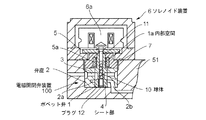
図7は本発明が適用されるディーゼルエンジン用電磁式ユニットインジェクタの縦断面図である。
図7において、50は電磁式ユニットインジェクタで、次のように構成されている。
51はインジェクタ本体、7は該インジェクタ本体51内に往復動自在に設けられたプランジャ、56及び55は該プランジャ7を往復動せしめるタペット及びタペットスプリング、8は該プランジャ7で燃料が加圧されるプランジャ室、9は燃料通路、52は前記プランジャ室8内の高圧燃料を図示しないエンジンの燃焼室内に噴射する噴孔52aを備えた燃料噴射ノズル、53は該燃料噴射ノズル52内に往復動自在に設けられた針弁、54は該針弁53の開、閉弁を司る針弁ばねである。
FIG. 7 is a longitudinal sectional view of an electromagnetic unit injector for a diesel engine to which the present invention is applied.
In FIG. 7,
51 is an injector body, 7 is a plunger reciprocally provided in the
100は電磁開閉弁装置で、次のように構成されている。
1はポペット弁、2は内部に該ポペット弁1が往復動自在に嵌合された弁座、5aはポペット弁ばね、2bは前記インジェクタ本体51内の燃料通路9に連通される燃料通路、3はスピル通路である。
6は電磁コイル6aを備えたソレノイド装置、5は前記ポペット弁1の上端に固定されて前記電磁コイル6aに吸引あるいは離間されるアーマチュアである。
1 is a poppet valve, 2 is a valve seat in which the
6 is a solenoid device provided with an
かかる電磁式ユニットインジェクタ50を備えたディーゼルエンジンの運転時において、
エンジンの燃料カム(図示省略)により作動せしめられる前記タペット56及びタペットスプリング55を介して往復駆動される前記プランジャ7によって高圧に加圧された燃料は、プランジャ室8内に溜められる。
そして、前記ソレノイド装置6の励磁によって前記電磁開閉弁装置100のポペット弁1が固定されたアーマチュア5が該ソレノイド装置6の電磁コイル6aに吸引されると該ポペット弁1と弁座2との間のシート部が閉じて、前記プランジャ室8から前記電磁開閉弁装置100内の燃料通路2b、インジェクタ本体51内の燃料通路9、燃料溜め52bに至る通路内の燃料圧力が上昇する。
該燃料圧力が前記針弁ばね54の開弁圧力を超えると、針弁53が開弁して燃料溜め52b内の高圧燃料が噴孔52aから図示しない燃焼室内に噴射される。
During operation of a diesel engine equipped with such an
The fuel pressurized to a high pressure by the
When the
When the fuel pressure exceeds the valve opening pressure of the
次いで、前記ソレノイド装置6が非励磁となると、前記アーマチュア5がポペット弁ばね5aの弾力によって下動し、前記ポペット弁1と弁座2とのシート部にはシート部通路が形成され、プランジャ室8内の燃料は、燃料通路9及び2bからシート部通路を通ってスピル通路3に排出される。
本発明はかかる電磁式ユニットインジェクタ50等の電磁制御燃料噴射装置における、電磁開閉弁装置100の改良に係るものである。
Next, when the
The present invention relates to an improvement of the electromagnetic on-off
図1は本発明の第1実施例(前提となる実施例)に係るディーゼルエンジン用電磁式ユニットインジェクタにおけるポペット弁を備えた電磁開閉弁装置の要部断面図である。
図1において、6はソレノイド装置、6aは該ソレノイド装置の電磁コイル、1は該ソレノイド装置6により往復駆動せしめられるポペット弁、5aはポペット弁ばね、2は内部に該ポペット弁1が往復動自在に嵌合された弁座で、該ポペット弁1との間にシート部4が形成されている。2aは前記燃料通路2bに連通される燃料溜め、3は弁座2に形成されたスピル通路である。
5は前記ポペット弁1の上端部に固定され前記電磁コイル6aに吸引あるいは離間されるアーマチュアである。
FIG. 1 is a cross-sectional view of a main part of an electromagnetic on-off valve device having a poppet valve in an electromagnetic unit injector for a diesel engine according to a first embodiment (a presupposed embodiment) of the present invention.
In FIG. 1, 6 is a solenoid device, 6a is an electromagnetic coil of the solenoid device, 1 is a poppet valve that is reciprocally driven by the
1aは前記ポペット弁1の内部に軸心1bに沿って形成された内部空間で、該内部空間1aは上部側を前記アーマチュア5の取付けボルト11によって塞がれ、下部側をプラグ12によって塞がれて、実質的に閉鎖空間となっている。
10は前記内部空間1aに収納された複数個の球体で、鋼球、ゴム球、プラスチック球等からなる一定質量を有する球体である。該球体10は、前記内部空間1aに、前記ポペット弁1の往復動によって該内部空間1a内を移動可能な程度に適当な間隔を存し、かつポペット弁1の往復動によって相互に接触可能に収納されている。
1a is an internal space formed along the
A plurality of
かかる第1実施例(前提となる実施例)において、前記ソレノイド装置6によって往復駆動せしめられるポペット弁1の内部に形成された閉塞空間である内部空間1aに、鋼球等からなる複数個の球体10を収納したので、燃料噴射始め時に前記ソレノイド装置6が励磁されて前記アーマチュア5を介して前記ポペット弁1が弁座2とのシート部4に着座し、該シート部4からバウンスしようとするとき、前記内部空間1a内の複数個の球体10には、これらの質量によってポペット弁1の運動方向と逆方向の慣性力が発生する。
In the first embodiment (a presupposed embodiment) , a plurality of spheres made of steel balls or the like are provided in an
そして、この慣性力によって前記球体10が該内部空間1a内をポペット弁1の運動方向と逆方向に移動して、前記取付けボルト11の内部空間1aに臨む下面(あるいは前記プラグ12の内部空間1aに臨む上面)を介してポペット弁1を押し、該ポペット弁のバウンス力(反撥力)を打ち消す。
この際において、ポペット弁1のバウンス時に前記複数個の球体10同士の接触及び該球体10と内部空間1aの内壁面との接触による摩擦抵抗によっても、前記ポペット弁1のバウンス力(反撥力)を打ち消すことができる。
The inertial force causes the
At this time, the bounce force (repulsive force) of the
図3は、かかる第1実施例(前提となる実施例)におけるポペット弁ストロークと前記球体10の可動範囲との関係を示す説明図(図1対応図)である。
図3に示すように、かかる第1実施例(前提となる実施例)において、前記複数個の球体10のポペット弁1の軸方向における可動範囲Lsを、ポペット弁ストロークLp以下(Ls≦Lp)に設定するのが好ましい。
FIG. 3 is an explanatory diagram (corresponding to FIG. 1) showing the relationship between the poppet valve stroke and the movable range of the
As shown in FIG. 3, in the first embodiment (premise embodiment) , the movable range Ls of the plurality of
このように構成すれば、ポペット弁1のストロークによって、前記内部空間1aに収納された複数個の球体10が必ず1回以上、好ましくは複数回ポペット弁1の内部で衝突するので、前記複数個の球体10の質量によって、確実にポペット弁1の運動方向と逆方向の慣性力が作用して、前記内部空間1aの底面または上面を介してポペット弁1のバウンス力を打ち消すことが可能となる。
尚、図3において、図1と同一の部材は同一の符号で示す。
According to this structure, the plurality of
In FIG. 3, the same members as those in FIG. 1 are denoted by the same reference numerals.
以上より、かかる第1実施例(前提となる実施例)によれば、前記ポペット弁1が弁座2とのシート部4に着座しバウンスしようとするとき、前記複数個の球体10によるポペット弁1の運動方向と逆方向の慣性力及び、該複数個の球体10同士の接触及び該球体10と内部空間1aの内壁面との接触による摩擦抵抗との相乗作用によって前記ポペット弁1のバウンス力(反撥力)を打ち消すことができ、前記従来の磁性粉体の慣性力のみによるバウンス抑制手段よりもバウンス抑制効果が格段に大きくなる。
これにより、ポペット弁1のバウンスにより発生する、燃料噴射終り及び噴射タイミングに不整の発生及びこれらに伴う燃料噴射量のばらつきや不整噴射の発生を、確実に防止できる。
As described above, according to the first embodiment (premise embodiment), when the
As a result, it is possible to reliably prevent the occurrence of irregularities in the end of fuel injection and the injection timing, the variation in the fuel injection amount, and the occurrence of irregular injection caused by the bounce of the
また、ポペット弁1の内部空間1aに収納される複数個の球体10は、一定質量を有する質量体であるので、該内部空間1aへの組み込み作業が簡単にでき、かつ組み込み時及び運転時に内部空間1aから外部の燃料油中に混入する恐れはなく、安全性及び取扱性も良好となる。
また、かかる第1実施例(前提となる実施例)において、前記ポペット弁1の内部空間1aに、燃料、潤滑油等の液体と共に前記球体10を封入することもできる。
このように構成すれば、前記内部空間1aに、前記球体10とともに燃料、潤滑油等の液体を同時に封入することで、さらに摩擦抵抗を大きくすることができ、バウンスの抑制効果が大きくなる。
In addition, since the plurality of
Further, in the first embodiment (a prerequisite embodiment) , the
If comprised in this way, by simultaneously enclosing liquid, such as a fuel and lubricating oil, with the said
図2は本発明の第2実施例(参考例)を示す図1対応図である。
かかる第2実施例(参考例)においては、前記ポペット弁1の内部空間1aに、前記第1実施例における球体10に代えて複数個の針状体15を収納している。該針状体15は、鋼線、ゴム棒、プラスチック棒等の針状あるいは棒状に形成されて、前記ポペット弁1の軸線1bの方向に向けて、ポペット弁1の往復動に従って該内部空間1a内を移動可能にかつ相互の外周面が接触可能に複数個収納されている。
その他の構成は図1の第1実施例と同様であり、これと同一の部材は同一の符号で示す。
かかる第2実施例(参考例)によれば、前記ポペット弁1の内部空間1aに収納された複数個の針状体15が、一定長さを有する針状あるいは棒状に形成されているので、ポペット弁1の軸線1b方向における針状体15同士の接触面積が大きくなって、該針状体15同士の接触による摩擦抵抗に伴うバウンス力の抑制効果が大きくなる。
その他の構成は図1に示される第1実施例と同様であり、これと同一の部材は同一の符号で示す。
FIG. 2 is a view corresponding to FIG. 1 showing a second embodiment (reference example) of the present invention.
In the second embodiment (reference example), a plurality of needle-like bodies 15 are accommodated in the
Other configurations are the same as those of the first embodiment of FIG. 1, and the same members are denoted by the same reference numerals.
According to the second embodiment (reference example), since the plurality of needle-like bodies 15 housed in the
Other configurations are the same as those of the first embodiment shown in FIG. 1, and the same members are denoted by the same reference numerals.
図4は本発明の第3実施例を示す図1対応図、図5はかかる第3実施例におけるポペット弁ストロークと前記球体10の可動範囲との関係を示す説明図(図4対応図)、図6は図4及び図5におけるZ部拡大図である。
かかる第3実施例においては、前記第1実施例と同様に、ポペット弁1の内部空間1aに複数個の球体10を、該ポペット弁1の往復動によって該内部空間1a内を移動可能な程度に適当な間隔を存し、かつポペット弁1の往復動によって相互に接触可能に収納するとともに、密閉された前記内部空間1aを封鎖するプラグ12に、該内部空間1aと外部の油通路つまり該ポペット弁1の周りの油通路とを連通する小孔13を設けている。
その他の構成は図1に示す第1実施例と同様であり、これと同一の部材は同一の符号で示す。
FIG. 4 is a diagram corresponding to FIG. 1 showing a third embodiment of the present invention, and FIG. 5 is an explanatory diagram showing the relationship between the poppet valve stroke and the movable range of the
In the third embodiment, similar to the first embodiment, a plurality of
Other configurations are the same as those of the first embodiment shown in FIG. 1, and the same members are denoted by the same reference numerals.
かかる第3実施例においては、ポペット弁1の往復動に従い該ポペット弁1内部の密閉された内部空間1aと外部の油通路とを連通する小孔13を燃料油が出入りすることによるダッシュポットの機能をそなえているので、ポペット弁1のシート部4への着座後のバウンス時に、かかるダッシュポット機能に伴うダンピング作用によってポペット弁1のバウンス力を抑制する。
また、ポペット弁1の内部空間1aに収納された複数個の球体10は、前記第1実施例と同様な慣性力によるバウンス力の抑制作用を行なう。
In the third embodiment, as the
Further, the plurality of
また、図5に示すように、かかる第3実施例においては、燃料油が前記小孔13を通って出入りする前記内部空間1aに収納された前記複数個の球体10のポペット弁1の軸方向における可動範囲Lsを、ポペット弁ストロークLp以下(Ls≦Lp)に設定するのが好ましい。
Further, as shown in FIG. 5, in this third embodiment, the axial direction of the
このように構成すれば、ポペット弁1のストロークによって、燃料油が前記小孔13を通って出入りする前記内部空間1aに収納された複数個の球体10が必ず1回以上、好ましくは複数回ポペット弁1の内部で衝突する。
これにより、前記複数個の球体10の質量によって、確実にポペット弁1の運動方向と逆方向の慣性力が作用して、前記内部空間1aの底面または上面を介してポペット弁1のバウンス力を打ち消すとともに、前記球体10とポペット弁1との相対速度に比例した燃料の粘性に伴う減衰効果も相乗されて、前記バウンス力の抑制効果がさらに大きくなる。
尚、図5において、図4と同一の部材は同一の符号で示す。
If comprised in this way, the several
As a result, the mass of the plurality of
In FIG. 5, the same members as those in FIG. 4 are denoted by the same reference numerals.
以上より、かかる第3実施例によれば、ポペット弁1の内部空間1aと外部の油通路とを連通する小孔13を備えてダッシュポットの機能を有するバウンス力の抑制手段と、前記第1実施例と同様な球体10の慣性力によるバウンス力の抑制手段とを組み合わせることによって、前記ダッシュポット機能に伴うバウンス力ダンピング作用と前記複数個の質量体の慣性力によるバウンス力抑制作用との相乗作用によって、バウンス力の抑制効果がさらに大きくなる。
尚、前記第1実施例の球体10に代えて、前記第2実施例の針状体15を内部空間1aに収納してもよい。
また、前記内部空間1aに球体10あるいは針状体15を収納せずに、前記小孔13によるダッシュポット機能のみでバウンス力を抑制することも可能である。
As described above, according to the third embodiment, the bounce force suppressing means having the small hole 13 communicating with the
Instead of the
Further, it is possible to suppress the bounce force only by the dashpot function by the small hole 13 without storing the
本発明によれば、ポペット弁の往復動により燃料噴射始めおよび終り時期を制御するように構成された電磁制御燃料噴射装置において、該ポペット弁の往復運動に伴う慣性力、摩擦力等の該ポペット弁のバウンス抑制力を有効に利用することにより、該ポペット弁のバウンス防止効果を向上できるとともに、安全性及び取扱性が向上せしめられたポペット弁を備えた電磁制御燃料噴射装置を提供できる。 According to the present invention, in the electromagnetically controlled fuel injection device configured to control the start and end timing of fuel injection by the reciprocating motion of the poppet valve, the poppet such as the inertial force and the frictional force accompanying the reciprocating motion of the poppet valve is provided. By effectively utilizing the bounce suppression force of the valve, the bounce prevention effect of the poppet valve can be improved, and an electromagnetically controlled fuel injection device including a poppet valve with improved safety and handling can be provided.
1 ポペット弁
1a 内部空間
2 弁座
2b 燃料通路
3 スピル通路
5 アーマチュア
6 ソレノイド装置
6a 電磁コイル
7 プランジャ
8 プランジャ室
10 球体
11 取付けボルト
12 プラグ
13 小孔
15 針状体
50 電磁式ユニットインジェクタ
100 電磁開閉弁装置
DESCRIPTION OF
Claims (2)
前記ポペット弁はポペット弁軸方向に沿って形成された内部空間を有し、該内部空間に複数個の金属球を含む球体からなる固体質量体がポペット弁の往復動方向に沿って一列状に配列されるとともに、該ポペット弁の運動方向と逆方向の慣性力によって可動可能に収納され、且つ前記ポペット弁の運動方向と逆方向の慣性力による移動の際に前記複数個の固体質量体同士の接触及び該固体質量体の前記内部空間の内壁面への接触によって固体質量体に摩擦抵抗が生じるように、該複数個の固体質量体同士がポペット弁軸方向に可動可能に配列され、
さらに、前記内部空間は前記ポペット弁の軸方向端部をプラグによって封鎖して形成され、該プラグに前記内部空間と外部の油通路とを連通する小孔を形成し、前記ポペット弁の往復動によって前記内部空間と外部の油通路との間を燃料が前記小孔を通って出入りすることによるダッシュポット機能を備え、前記複数個の固体質量体の慣性力による前記ポペット弁のバウンス力の抑制と、前記プラグに形成した小孔によって生じる前記ダッシュポット機能による前記ポペット弁のバウンス力の抑制とを組み合わせて作用せしめるように構成したことを特徴とするポペット弁を備えた電磁制御燃料噴射装置。 A poppet valve that is driven back and forth by a solenoid device opens and closes the fuel passage to the plunger chamber where the fuel is compressed to a high pressure by the plunger and the spill passage to the drainage system, thereby controlling the start of fuel injection and the end of fuel injection. In an electromagnetically controlled fuel injection device configured to control,
The poppet valve has an internal space formed along the poppet valve axial direction, and solid mass bodies made of spheres including a plurality of metal balls are arranged in a line along the reciprocating direction of the poppet valve. The plurality of solid mass bodies are arranged so as to be movable by an inertia force in a direction opposite to the movement direction of the poppet valve and moved by an inertia force in a direction opposite to the movement direction of the poppet valve. contact and as solid masses in the frictional resistance by contact to the inner wall surface of the inner space of the solid mass occurs, several solid mass bodies plurality is movably arranged in the poppet valve axis,
Further, the internal space is formed by sealing an axial end of the poppet valve with a plug, and a small hole is formed in the plug to communicate the internal space with an external oil passage. And a dashpot function in which fuel enters and exits between the internal space and an external oil passage through the small hole, and suppresses the bounce force of the poppet valve by the inertial force of the plurality of solid mass bodies And an electromagnetically controlled fuel injection device having a poppet valve, wherein the poppet valve is configured to act in combination with suppression of the bounce force of the poppet valve by the dashpot function generated by a small hole formed in the plug .
Priority Applications (5)
| Application Number | Priority Date | Filing Date | Title |
|---|---|---|---|
| JP2005334725A JP4634285B2 (en) | 2005-02-24 | 2005-11-18 | Electromagnetic control fuel injection device with poppet valve |
| US11/359,435 US7350539B2 (en) | 2005-02-24 | 2006-02-23 | Electromagnetic controlled fuel injection apparatus with poppet valve |
| DE200660003581 DE602006003581D1 (en) | 2005-02-24 | 2006-02-24 | Electromagnetically controlled fuel injection arrangement with valve |
| AT06110374T ATE414224T1 (en) | 2005-02-24 | 2006-02-24 | ELECTROMAGNETICALLY CONTROLLED FUEL INJECTION ARRANGEMENT WITH VALVE |
| EP20060110374 EP1703120B1 (en) | 2005-02-24 | 2006-02-24 | Electromagnetic controlled fuel injection apparatus with poppet valve |
Applications Claiming Priority (2)
| Application Number | Priority Date | Filing Date | Title |
|---|---|---|---|
| JP2005049304 | 2005-02-24 | ||
| JP2005334725A JP4634285B2 (en) | 2005-02-24 | 2005-11-18 | Electromagnetic control fuel injection device with poppet valve |
Publications (3)
| Publication Number | Publication Date |
|---|---|
| JP2006266254A JP2006266254A (en) | 2006-10-05 |
| JP2006266254A5 JP2006266254A5 (en) | 2008-03-21 |
| JP4634285B2 true JP4634285B2 (en) | 2011-02-16 |
Family
ID=36084414
Family Applications (1)
| Application Number | Title | Priority Date | Filing Date |
|---|---|---|---|
| JP2005334725A Expired - Fee Related JP4634285B2 (en) | 2005-02-24 | 2005-11-18 | Electromagnetic control fuel injection device with poppet valve |
Country Status (5)
| Country | Link |
|---|---|
| US (1) | US7350539B2 (en) |
| EP (1) | EP1703120B1 (en) |
| JP (1) | JP4634285B2 (en) |
| AT (1) | ATE414224T1 (en) |
| DE (1) | DE602006003581D1 (en) |
Families Citing this family (7)
| Publication number | Priority date | Publication date | Assignee | Title |
|---|---|---|---|---|
| JP4227965B2 (en) * | 2005-02-28 | 2009-02-18 | 三菱重工業株式会社 | Electromagnetic control fuel injection device |
| JP2008045486A (en) * | 2006-08-16 | 2008-02-28 | Yanmar Co Ltd | Accumulator fuel injection device |
| JP4719140B2 (en) * | 2006-12-20 | 2011-07-06 | 三菱重工業株式会社 | Electromagnetic valve device and fuel injection device for an engine equipped with the same |
| DE102009006987B3 (en) * | 2009-01-31 | 2010-09-30 | Deutsches Zentrum für Luft- und Raumfahrt e.V. | magnetic valve |
| US7942349B1 (en) | 2009-03-24 | 2011-05-17 | Meyer Andrew E | Fuel injector |
| EP2363592A1 (en) * | 2010-02-25 | 2011-09-07 | Continental Automotive GmbH | Injection valve |
| US11118698B2 (en) * | 2018-07-23 | 2021-09-14 | Pratt & Whiiney Canada Corp. | Damping mechanism for valves |
Citations (4)
| Publication number | Priority date | Publication date | Assignee | Title |
|---|---|---|---|---|
| JPH05223031A (en) * | 1992-02-12 | 1993-08-31 | Nippondenso Co Ltd | Fuel injection valve |
| JPH07167331A (en) * | 1993-09-22 | 1995-07-04 | Robert Bosch Gmbh | Solenoid valve |
| US6021999A (en) * | 1998-08-11 | 2000-02-08 | Caterpillar Inc. | Bounce suppression device for high speed poppet valve |
| JP2002098024A (en) * | 2000-09-26 | 2002-04-05 | Mitsubishi Heavy Ind Ltd | Electronically controlled fuel injection system |
Family Cites Families (11)
| Publication number | Priority date | Publication date | Assignee | Title |
|---|---|---|---|---|
| US455913A (en) * | 1891-07-14 | Means for equalizing the pressure of gas in gas service-pipes | ||
| US4566485A (en) * | 1984-11-19 | 1986-01-28 | Ruhle James L | Free-floating neutrally-buoyant reciprocating pump valve for abrasive fluids |
| US5392811A (en) * | 1993-11-02 | 1995-02-28 | Caterpillar Inc. | High pressure fuel system valve |
| US5443209A (en) * | 1994-08-02 | 1995-08-22 | Diesel Technology Company | High pressure diesel fuel injector for internal combustion engines |
| US5954487A (en) | 1995-06-23 | 1999-09-21 | Diesel Technology Company | Fuel pump control valve assembly |
| US5984259A (en) * | 1997-11-26 | 1999-11-16 | Saturn Electronics & Engineering, Inc. | Proportional variable force solenoid control valve with armature damping |
| DE19820341C2 (en) * | 1998-05-07 | 2000-04-06 | Daimler Chrysler Ag | Actuator for a high pressure injector for liquid injection media |
| US6109541A (en) * | 1998-07-23 | 2000-08-29 | Caterpillar Inc. | Apparatus for reducing the bounce of a poppet valve |
| US6145805A (en) * | 1999-08-23 | 2000-11-14 | Caterpillar Inc. | Liquid control valve assembly with local damping and hydraulically actuated fuel injector using same |
| US6874703B2 (en) * | 2002-06-11 | 2005-04-05 | General Motors Corporation | Anti-bounce needle valve for a fuel injector |
| US6702207B2 (en) * | 2002-07-16 | 2004-03-09 | Robert Bosch Gmbh | Fuel injector control module with unidirectional dampening |
-
2005
- 2005-11-18 JP JP2005334725A patent/JP4634285B2/en not_active Expired - Fee Related
-
2006
- 2006-02-23 US US11/359,435 patent/US7350539B2/en active Active
- 2006-02-24 EP EP20060110374 patent/EP1703120B1/en not_active Expired - Fee Related
- 2006-02-24 AT AT06110374T patent/ATE414224T1/en not_active IP Right Cessation
- 2006-02-24 DE DE200660003581 patent/DE602006003581D1/en not_active Expired - Fee Related
Patent Citations (4)
| Publication number | Priority date | Publication date | Assignee | Title |
|---|---|---|---|---|
| JPH05223031A (en) * | 1992-02-12 | 1993-08-31 | Nippondenso Co Ltd | Fuel injection valve |
| JPH07167331A (en) * | 1993-09-22 | 1995-07-04 | Robert Bosch Gmbh | Solenoid valve |
| US6021999A (en) * | 1998-08-11 | 2000-02-08 | Caterpillar Inc. | Bounce suppression device for high speed poppet valve |
| JP2002098024A (en) * | 2000-09-26 | 2002-04-05 | Mitsubishi Heavy Ind Ltd | Electronically controlled fuel injection system |
Also Published As
| Publication number | Publication date |
|---|---|
| US20060185650A1 (en) | 2006-08-24 |
| JP2006266254A (en) | 2006-10-05 |
| US7350539B2 (en) | 2008-04-01 |
| EP1703120A1 (en) | 2006-09-20 |
| EP1703120B1 (en) | 2008-11-12 |
| ATE414224T1 (en) | 2008-11-15 |
| DE602006003581D1 (en) | 2008-12-24 |
Similar Documents
| Publication | Publication Date | Title |
|---|---|---|
| JP4634285B2 (en) | Electromagnetic control fuel injection device with poppet valve | |
| KR100730841B1 (en) | Fuel injection device | |
| KR100347430B1 (en) | Collision Relief Amateur and Needle Valve Assembly | |
| KR100531744B1 (en) | Electromagnetic metering valve for fuel injectors | |
| US7252245B2 (en) | Fuel injection valve | |
| JP2006266254A5 (en) | ||
| EP1045135B1 (en) | Fuel-injection valve | |
| US5967413A (en) | Damped solenoid actuated valve and fuel injector using same | |
| CN101535625B (en) | Injector for injecting fuel | |
| RU2011102820A (en) | FUEL INJECTOR WITH AN ELECTROMAGNET ANCHOR CONSISTING OF TWO PARTS | |
| US7467781B2 (en) | Poppet valve device and electronic controlled fuel injection apparatus equipped with the device | |
| Ganser | Common rail injectors for 2000 bar and beyond | |
| US20040011893A1 (en) | Fuel injector control module with dampening | |
| EP0645535B1 (en) | A unit type fuel injector for internal combustion engines | |
| US6021999A (en) | Bounce suppression device for high speed poppet valve | |
| CN111566337A (en) | Valve for metering fluids | |
| EP1063419A2 (en) | Fuel injection valve | |
| GB2339845A (en) | I.c. engine fuel injector with movable weight to reduce poppet valve bounce | |
| US20190120189A1 (en) | Solenoid valve for controlling fluids | |
| JP2005069233A (en) | Fuel injection valve and internal combustion engine loading the same | |
| CA3184240A1 (en) | Solenoid valve | |
| JPH11229998A (en) | Fuel injector | |
| JP3677583B2 (en) | Fuel injection valve and internal combustion engine equipped with the same | |
| JPH06193531A (en) | Fuel injecting device | |
| JPH0828402A (en) | Solenoid valve |
Legal Events
| Date | Code | Title | Description |
|---|---|---|---|
| A521 | Request for written amendment filed |
Free format text: JAPANESE INTERMEDIATE CODE: A523 Effective date: 20080125 |
|
| A621 | Written request for application examination |
Free format text: JAPANESE INTERMEDIATE CODE: A621 Effective date: 20080125 |
|
| A977 | Report on retrieval |
Free format text: JAPANESE INTERMEDIATE CODE: A971007 Effective date: 20090820 |
|
| A131 | Notification of reasons for refusal |
Free format text: JAPANESE INTERMEDIATE CODE: A131 Effective date: 20090821 |
|
| A521 | Request for written amendment filed |
Free format text: JAPANESE INTERMEDIATE CODE: A523 Effective date: 20091019 |
|
| A131 | Notification of reasons for refusal |
Free format text: JAPANESE INTERMEDIATE CODE: A131 Effective date: 20091224 |
|
| A521 | Request for written amendment filed |
Free format text: JAPANESE INTERMEDIATE CODE: A523 Effective date: 20100222 |
|
| A02 | Decision of refusal |
Free format text: JAPANESE INTERMEDIATE CODE: A02 Effective date: 20100521 |
|
| A521 | Request for written amendment filed |
Free format text: JAPANESE INTERMEDIATE CODE: A523 Effective date: 20100823 |
|
| A911 | Transfer to examiner for re-examination before appeal (zenchi) |
Free format text: JAPANESE INTERMEDIATE CODE: A911 Effective date: 20100826 |
|
| TRDD | Decision of grant or rejection written | ||
| A01 | Written decision to grant a patent or to grant a registration (utility model) |
Free format text: JAPANESE INTERMEDIATE CODE: A01 Effective date: 20101022 |
|
| A01 | Written decision to grant a patent or to grant a registration (utility model) |
Free format text: JAPANESE INTERMEDIATE CODE: A01 |
|
| A61 | First payment of annual fees (during grant procedure) |
Free format text: JAPANESE INTERMEDIATE CODE: A61 Effective date: 20101118 |
|
| R151 | Written notification of patent or utility model registration |
Ref document number: 4634285 Country of ref document: JP Free format text: JAPANESE INTERMEDIATE CODE: R151 |
|
| FPAY | Renewal fee payment (event date is renewal date of database) |
Free format text: PAYMENT UNTIL: 20131126 Year of fee payment: 3 |
|
| S111 | Request for change of ownership or part of ownership |
Free format text: JAPANESE INTERMEDIATE CODE: R313111 |
|
| R350 | Written notification of registration of transfer |
Free format text: JAPANESE INTERMEDIATE CODE: R350 |
|
| LAPS | Cancellation because of no payment of annual fees |