EP2055871B1 - Coin deposit cupboard lock - Google Patents
Coin deposit cupboard lock Download PDFInfo
- Publication number
- EP2055871B1 EP2055871B1 EP20080167517 EP08167517A EP2055871B1 EP 2055871 B1 EP2055871 B1 EP 2055871B1 EP 20080167517 EP20080167517 EP 20080167517 EP 08167517 A EP08167517 A EP 08167517A EP 2055871 B1 EP2055871 B1 EP 2055871B1
- Authority
- EP
- European Patent Office
- Prior art keywords
- coin
- bolt
- lock according
- locker lock
- gauging
- Prior art date
- Legal status (The legal status is an assumption and is not a legal conclusion. Google has not performed a legal analysis and makes no representation as to the accuracy of the status listed.)
- Not-in-force
Links
Images


Classifications
-
- E—FIXED CONSTRUCTIONS
- E05—LOCKS; KEYS; WINDOW OR DOOR FITTINGS; SAFES
- E05B—LOCKS; ACCESSORIES THEREFOR; HANDCUFFS
- E05B47/00—Operating or controlling locks or other fastening devices by electric or magnetic means
- E05B47/06—Controlling mechanically-operated bolts by electro-magnetically-operated detents
- E05B47/0603—Controlling mechanically-operated bolts by electro-magnetically-operated detents the detent moving rectilinearly
-
- G—PHYSICS
- G07—CHECKING-DEVICES
- G07C—TIME OR ATTENDANCE REGISTERS; REGISTERING OR INDICATING THE WORKING OF MACHINES; GENERATING RANDOM NUMBERS; VOTING OR LOTTERY APPARATUS; ARRANGEMENTS, SYSTEMS OR APPARATUS FOR CHECKING NOT PROVIDED FOR ELSEWHERE
- G07C9/00—Individual registration on entry or exit
- G07C9/00174—Electronically operated locks; Circuits therefor; Nonmechanical keys therefor, e.g. passive or active electrical keys or other data carriers without mechanical keys
- G07C9/00944—Details of construction or manufacture
-
- E—FIXED CONSTRUCTIONS
- E05—LOCKS; KEYS; WINDOW OR DOOR FITTINGS; SAFES
- E05B—LOCKS; ACCESSORIES THEREFOR; HANDCUFFS
- E05B47/00—Operating or controlling locks or other fastening devices by electric or magnetic means
- E05B47/0001—Operating or controlling locks or other fastening devices by electric or magnetic means with electric actuators; Constructional features thereof
- E05B47/0002—Operating or controlling locks or other fastening devices by electric or magnetic means with electric actuators; Constructional features thereof with electromagnets
-
- G—PHYSICS
- G07—CHECKING-DEVICES
- G07C—TIME OR ATTENDANCE REGISTERS; REGISTERING OR INDICATING THE WORKING OF MACHINES; GENERATING RANDOM NUMBERS; VOTING OR LOTTERY APPARATUS; ARRANGEMENTS, SYSTEMS OR APPARATUS FOR CHECKING NOT PROVIDED FOR ELSEWHERE
- G07C9/00—Individual registration on entry or exit
- G07C9/00174—Electronically operated locks; Circuits therefor; Nonmechanical keys therefor, e.g. passive or active electrical keys or other data carriers without mechanical keys
- G07C9/00857—Electronically operated locks; Circuits therefor; Nonmechanical keys therefor, e.g. passive or active electrical keys or other data carriers without mechanical keys where the code of the data carrier can be programmed
-
- Y—GENERAL TAGGING OF NEW TECHNOLOGICAL DEVELOPMENTS; GENERAL TAGGING OF CROSS-SECTIONAL TECHNOLOGIES SPANNING OVER SEVERAL SECTIONS OF THE IPC; TECHNICAL SUBJECTS COVERED BY FORMER USPC CROSS-REFERENCE ART COLLECTIONS [XRACs] AND DIGESTS
- Y10—TECHNICAL SUBJECTS COVERED BY FORMER USPC
- Y10T—TECHNICAL SUBJECTS COVERED BY FORMER US CLASSIFICATION
- Y10T70/00—Locks
- Y10T70/50—Special application
Definitions
- the invention relates to a cabinet closure with a housing and arranged therein by actuating a handle movable latch, with a Einsteckschacht for inserting a coin, with a scanning device for scanning the diameter of the inserted into the insertion slot into a scanning position coin, wherein the scanning device so with a locking device cooperates, that the bolt is displaceable only with a mating diameter having coin.
- Such a cabinet lock is from the DE 198 32 516 A1 previously known.
- the previously known lock for a locking system has a housing, a displaceable in the housing of a handle latch, wherein the latch is held by means of a locking device in its back-closed position. This locking device is released to preclose the bolt when a coin is inserted into a plug-in slot, which has a suitable diameter.
- the lock has a scanning device for sensing the diameter of the coin. If the latch is closed again by actuating a handle, the coin falls into an output slot.
- the DE 10 2006 034 292 describes a cabinet lock in which a key secret must be entered into a lock to the bolt lock.
- the key secret can be entered via a keyboard.
- the lock is also able to read a transponder in which the key secret is stored.
- a coin deposit lock is known, which is used in shopping carts.
- the lock has a plug-in slot. By inserting the coin a lock is released.
- the invention has for its object to further develop a generic cabinet closure nutzsvorteilhaft.
- each claim represents an independent solution to the problem and can be combined with any other claim.
- the scanning device forms a holding jaw, which holds the partially in the scanning position accessible from outside in the insertion slot coin with vor fundamentalem bolt against pulling out.
- the coin is inserted into the insertion slot of the lock housing into a scanning position.
- the scanning device scans the diameter of the coin. It is a maximum insertion depth, in which the coin is still accessible from the outside, but due to the holding function of the holding jaw can not be pulled out of the insertion slot.
- a positive retention of the coin is preferably provided in the scanning position.
- the coin is preferably gripped partially like a pliers, wherein a holding jaw is formed by a swing arm mounted pivotably about a housing-fixed axis.
- Another holding jaw can be firmly connected to the housing.
- the two holding jaws enclose the coin beyond its region of greatest diameter, so that it can only be pulled out again after the two holding jaws have moved away from the insertion shaft.
- the latter is preferably displaceable transversely to Münzeinsteckides.
- the rocker preferably has a bearing leg, at the end of the axis is articulated.
- the holding jaw preferably protrudes substantially transversely from the bearing leg.
- the rocker forms a flanked by at least one locking flank tour recess.
- a bolt associated to the touring pin can occur when a matching coin in the Plug-in shaft is inserted.
- At the Tourenaus thereafterung can join a guide groove.
- the stationary holding jaw can be relocated. It can be fixed, for example by means of screws on the lock housing. By loosening the screws, the distance between the two holding jaws in the release position can be adjusted.
- the insertion shaft preferably has a bulge, in which a portion of the inserted coin is located. The bulge extends over an area large enough for the coin to be grasped between two fingers to be pulled out of the insertion slot. The coin is inserted substantially only for fürmesserabtastung in the insertion slot.
- the lock housing has a blocking element.
- the latter is accessible from the outside of the housing.
- This blocking element is able to fix the rocker or the TourenausEnglishung in a position in which the TourenausEnglishung lies in the path of movement of the touring pin.
- the blocking element may form a blocking pin, which engages in the blocking position in an end portion of the guide groove adjoining the touring recess so as to position-fix the rocker in the pivot position corresponding to the release position.
- the bar lock takes place in the known manner via a crank pin, which is actuated by a handle. This engages in an engagement opening of the bolt to vorschmother the bolt.
- the lock additionally has a locking device with which the bolt can be held in the pre-closed position.
- the locking device In addition, can also hold the bolt in the back-closed position.
- the locking device can be brought from a blocking position to a release position. This can be done in a known manner, for example by pressing a key.
- the blocking device is released by reading an electronic key secret, wherein the key secret inserted in a transponder, which is read in a known manner by the locking device. It may further be provided that the key secret is a PIN which is entered via a keypad.
- the lock may include a fingerprint reader to read the fingerprint of a user. If the key secret is correctly entered, the locking device moves to the release position. The bolt can be preconnected. The locking device holds it in the locked position until the correct key secret is entered again.
- the lock can have a cashier function. For this purpose, the lock can be opened with a parent key secret. The coin can be removed in the locked back position. With an auxiliary tool, which is inserted into the insertion slot, the two jaws are brought to the appropriate distance by the touring pin can enter into the Tourenaus founded. By means of the blocking device, the holding jaw can be temporarily tied up in this position. It is envisaged that the trunnion brings the blocking device from the blocking position with fully locked bolt.
- the scanning device with an electrical button or a Switch cooperates. Depending on the operating position of the scanning device, a circuit is closed or opened a circuit. In this way, an electrical signal can be provided which changes its state when a suitable coin is inserted into the insertion slot. This electrical signal can be used to block or release the bolt.
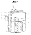
- cabinet lock can be attached to a cabinet door 25. It has a housing 1, which can be fixed inside the cabinet door 25 on the inside of the cabinet.
- the closure has a front panel 26 which can be fastened on the outside of the door.
- the front panel 26 has a handle 27 with which a crank pin 35 can be pivoted to displace a latch 3 arranged in the housing 1 in a latch displacement direction.
- the front panel 26 also has a keypad 28 for inputting a numerical code.
- a transponder reading device may be arranged to read a transponder.
- the shutter may also be connected to a fingerprint reader.
- the housing 1 is made of plastic.
- the bolt 3 is preferably made of metal.
- the two locking stages 31, 34 is formed.
- In the locking slot 30 engages a locking extension 32 of a locking lever 33 a.
- the locking lever 33 can be pivoted by means of an electromagnet 29. It can assume a blocking position, in which the locking extension 32 is located in front of the locking stage 31 vor stressedem latch, so that the vorrosee latch of the handle 27 is not Wegschteurbar.
- the bolt can also be acted upon in the bolt retraction direction by a compression or tension spring, so that a single displacement of the locking lever 33 from the blocking position into a release position is required to retract the latch 3 from a latch position.
- the crank pin 35 which engages in a recess of the bolt 3, must be rotated.
- the locking slot 30 forms an additional blocking stage 34. Before this blocking stage 34, the locking extension 32 can lie in the locked-back locking position in order to lock the bolt 3 against preclusion.
- the insertion shaft 4 is formed by two shaft walls 22, 23, wherein a rear shaft wall 22 extends over the entire wide surface of the insertion shaft 4.
- the front-side shaft wall 23 extends only over a partial region of the broad side of the insertion shaft 4 and forms a Münzeinsteckbegrenzungssteg 24.
- the coin 5 is in fully inserted position. In this position, a portion of the coin 5 is located within the bulge 19. The apex of protruding from the housing 1 coin is outside the imaginary Einsteckschachtrandkante.
- a holding jaw 8 is attached on the shaft wall 22 .
- the holding jaw 8 is fastened with screws on the shaft wall 22 such that it can be adjusted in position.
- the fixed holding jaw 8 is transverse to Münzeinsteckides a movable holding jaw 7 opposite. Both holding jaws 7, 8 are able to partially enclose the coin 5 in such a way that it is positively secured against being pulled out of the insertion shaft 4.
- the coin 5 is therefore tied in a peripheral area> 180 °.
- the movable holding jaw 7 is associated with a rocker 6.
- the rocker 6 is designed T-shaped.
- the two T-legs form a bearing leg 10 and a guide groove 12.
- the T-bar forms the said movable holding jaw 7.
- the bearing leg 10 extends substantially parallel to the displacement direction of the bolt 3.
- a Swivel axis 9 attached to the housing or on the shaft wall 22.
- a substantially rectangular rib structure In the node of the rocker 6 is a substantially rectangular rib structure.
- the ribs 13, 14, 15, 16 and 17 frame up to a tour recess 11 a substantially rectangular space in which a touring pin 18 of the bolt 3 engages.
- the two ribs 13, 14 flanking the route recess 11 form blocking edges.
- the rib structure is continued in the direction of displacement of the bolt 3 behind the Tourenaus originallyung 11 and forms a guide groove 12 for the touring pin 18th
- the touring pin 18 is formed by a rectangular portion of the bolt 3 projecting beyond the back of the bolt 3. At the appropriate point protrudes over the front of the bolt 3 a round pin.
- the touring pin 18 is located on the opposite side of the locking slot 30 and is associated with an extension of the bolt 3.
- a blocking member 20 is arranged in the housing 1. This can be relocated with a needle-shaped tool 37, which is inserted into a housing opening 36. With a screw, not shown, it can be fixed in place.
- the blocking element 20 has a blocking pin 21 which can be inserted into the guide groove 12, so as to fix the rocker 6 in a position in which the TourenausEnglishung 11 lies in the path of movement of the touring pin 18. In this position, the bolt 3 can be moved even when not inserted coin 5. If the blocking element 20 is not blocked in its blocking position by means of a screw or the like, then the towing pin 18 can push the blocking pin 21 out of the guide groove 12 again when the catch 3 is completely closed.
- the rocker 6 is spring-loaded by a tension or compression spring, not shown, that when not inserted coin 5 of the touring pin 18 is located in front of the upper locking edge 13. This corresponds to a pivotal position of the rocker 6, in which the movable holding jaw 7 assumes a position closest to the fixed holding jaw 8. In this position, the bolt 3 can not be preconnected because the touring pin 18 can not enter the TourenausEnglishung 11, but runs against the locking edge 14 when the bolt 3 is to be moved.
- a coin 5 To be able to close the closure, a coin 5 must first be inserted into the insertion slot 4. The coin 5 is completely inserted into the insertion shaft 4 until it rests against the shaft bottom 24. In this state, there is still a sufficiently large portion of the coin 5 outside of the insertion shaft 4 or in the bulge 19, so that the Coin 5 by attack with two fingers from the insertion slot 4 can be pulled out again.
- the two holding jaws 7, 8 are initially spread apart by displacement of the movable holding jaw 7, then slightly approaching again until the coin 5 is held by a form-fitting Operaumgriff. If the coin 5 has the correct diameter, then the tour recess 11 lies in the movement path of the touring pin 18. When the blocking lever 33 is released, the bolt 3 can be locked in by actuating the handle 27. The touring pin 18 dives through the tour recess 11 and enters the flanked by two ribs guide groove 12 a. Once the touring pin 18 is immersed in the guide groove 12, the rocker 6 can not be pivoted. The coin 5 is thus tied in the insertion shaft 4 between the two holding jaws 7, 8.
- the latch 3 can be prefaced to its end position, in which the locking extension 32 occurs behind the locking step 31, so as to hold the latch 3 in the initial position.
- the bolt retraction is preferably carried out via a tension spring, not shown, as shown in the DE 198 32 516 A1 is described.
- the towing pin 18 is in front of the blocking flank 13 when the coin 5 is inserted.
- the bolt feed is blocked. If a coin 5 with a diameter that is too large is inserted into the insertion shaft 4, then the touring pin 18 is in front of the lower blocking edge 14 when the coin is fully inserted.
- the bolt 3 can not be displaced even in this position.
- the holding jaw 7 has a fferenein loft opening. If a screw is screwed into this screw-in opening, the pivotability of the rocker 6 is blocked.
- the fferenein loft opening of the holding jaw 7 is preferably aligned with a threaded opening of the shaft wall 23.
- the threaded opening is positioned such that in the screwed state, the rocker in Fig. 5 illustrated position occupies, in which the touring pin 18 is located in front of the tour recess 11, so that the bolt 3 can be preconnected.
- the lock can be used with such a permanently fixed rocker 6 as a cabinet lock without pledge function.
- the scanning device 7, 8 has a button or a microswitch.
- the button can be actuated by the rocker.
- the button is arranged so that it closes a circuit when the rocker their in Fig. 5 shown pivot position assumes that corresponds to the pivotal position with inserted matching coin 5.
- the circuit is not closed.
- the displacement lock of the bolt 3 is then preferably exerted electromagnetically, for example by the electromagnet 29. This can only relocate the barrier extension 32 in the release position when the circuit of the electrical scanning device is closed. Alternatively, it is also possible that an otherwise closed circuit is opened when properly inserted coin.
- a switching flag of a button or a switch directly scans the coin, so as to provide an electrical scanning signal.
Description
Die Erfindung betrifft einen Schrankverschluss mit einem Gehäuse und einem darin angeordneten durch Betätigen einer Handhabe verlagerbaren Riegel, mit einem Einsteckschacht zum Einstecken einer Münze, mit einer Abtastvorrichtung zum Abtasten des Durchmessers der in den Einsteckschacht bis in eine Abtaststellung eingesteckten Münze, wobei die Abtastvorrichtung derart mit einer Sperreinrichtung zusammenwirkt, dass der Riegel nur bei einer einen passenden Durchmesser aufweisenden Münze verlagerbar ist.The invention relates to a cabinet closure with a housing and arranged therein by actuating a handle movable latch, with a Einsteckschacht for inserting a coin, with a scanning device for scanning the diameter of the inserted into the insertion slot into a scanning position coin, wherein the scanning device so with a locking device cooperates, that the bolt is displaceable only with a mating diameter having coin.
Ein derartiger Schrankverschluss ist aus der
Die
Aus der
Der Erfindung liegt die Aufgabe zugrunde, einen gattungsgemäßen Schrankverschluss gebrauchsvorteilhaft weiterzubilden.The invention has for its object to further develop a generic cabinet closure nutzsvorteilhaft.
Gelöst wird die Aufgabe durch die in den Ansprüchen angegebene Erfindung, wobei jeder Anspruch eine eigenständige Lösung der Aufgabe darstellt und mit jedem anderen Anspruch kombinierbar ist.The object is achieved by the invention specified in the claims, each claim represents an independent solution to the problem and can be combined with any other claim.
Zunächst und im wesentlichen wird vorgeschlagen, dass die Abtastvorrichtung eine Haltebacke ausbildet, die die in der Abtaststellung bereichsweise von außen zugänglich im Einsteckschacht steckende Münze bei vorgeschlossenem Riegel gegen ein Herausziehen festhält. Erfindungsgemäß wird die Münze in den Einsteckschacht des Schlossgehäuses bis in eine Abtaststellung eingeschoben. In dieser Abtaststellung tastet die Abtastvorrichtung den Durchmesser der Münze ab. Es handelt sich dabei um eine maximale Einstecktiefe, in der die Münze zwar noch von außen greifbar ist, aber zufolge der haltenden Funktion der Haltebacke nicht aus dem Einsteckschacht herausgezogen werden kann. Bevorzugt ist hierzu eine formschlüssige Halterung der Münze in der Abtaststellung vorgesehen. Die Münze wird dabei bevorzugt zangenartig teilumgriffen, wobei eine Haltebacke von einer um eine gehäusefeste Achse schwenkbar gelagerten Schwinge ausgebildet ist. Eine weitere Haltebacke kann fest mit dem Gehäuse verbunden sein. Die beiden Haltebacken umgreifen die Münze über ihren Bereich des größten Durchmessers hinaus, so dass sie nur nach einem Voneinanderwegbewegen der beiden Haltebacken aus dem Einsteckschacht wieder herausziehbar ist. Mit der Münze selbst erfolgt keine Betätigung des Riegels. Letzterer ist bevorzugt quer zur Münzeinsteckrichtung verlagerbar. Die Schwinge besitzt bevorzugt einen Lagerschenkel, an dessen Ende die Achse angelenkt ist. Die Haltebacke ragt bevorzugt im wesentlichen quer von dem Lagerschenkel ab. Die Schwinge bildet eine von mindestens einer Sperrflanke flankierte Tourenausnehmung aus. In diese Tourenausnehmung kann ein dem Riegel zugeordneter Tourenstift eintreten, wenn eine passende Münze in den Einsteckschacht eingesteckt ist. An die Tourenausnehmung kann sich eine Führungsnut anschließen. Diese erstreckt sich bei eingesteckter passender Münze im wesentlichen parallel zur Riegelverlagerungsrichtung. Während sich die bewegliche Haltebacke im wesentlichen quer zur Riegelverlagerungsrichtung erstreckt, erstreckt sich der Lagerschenkel parallel zur Verlagerungsrichtung des Riegels. Die ortsfeste Haltebacke kann ortsverlagert werden. Sie kann beispielsweise mittels Schrauben am Schlossgehäuse befestigt sein. Durch Lösen der Schrauben kann der Abstand der beiden Haltebacken in der Freigabestellung eingestellt werden. Der Einsteckschacht besitzt bevorzugt eine Ausbuchtung, in welcher ein Teilbereich der eingesteckten Münze liegt. Die Ausbuchtung erstreckt sich über eine Fläche, die groß genug ist, damit die Münze zwischen zwei Finger gefasst werden kann, um aus dem Einsteckschacht herausgezogen werden zu können. Die Münze wird im wesentlichen lediglich zur Durchmesserabtastung in den Einsteckschacht eingesteckt. Während des Einsteckens der Münze wird lediglich die Sperrvorrichtung von einer Sperrstellung in eine Freigabestellung verlagert. Eine Riegelverlagerung durch die Münze ist nicht vorgesehen. In einer Weiterbildung der Erfindung besitzt das Schlossgehäuse ein Blockierelement. Letzteres ist von der Gehäuseaußenseite her zugänglich. Dieses Blockierelement ist in der Lage, die Schwinge bzw. die Tourenausnehmung in einer Position zu fixieren, in der die Tourenausnehmung in der Bewegungsbahn des Tourenstiftes liegt. Im blockierten Zustand kann somit das Schloss ohne Pfandfunktion betätigt werden. Das Blockierelement kann einen Blockierzapfen ausbilden, der in der Blockierstellung in einen Endabschnitt der sich an die Tourenausnehmung anschließenden Führungsnut eingreift, um so die Schwinge in der der Freigabestellung entsprechenden Schwenkstellung lagezufixieren. Der Riegelvorschluss erfolgt in der bekannten Weise über einen Kurbelzapfen, der von einer Handhabe betätigt wird. Dieser greift in eine Eingriffsöffnung des Riegels ein, um den Riegel vorzuschließen. Das Schloss weist zusätzlich eine Sperrvorrichtung auf, mit der der Riegel in der vorgeschlossenen Stellung gehalten werden kann. Die Sperrvorrichtung kann darüber hinaus auch zusätzlich den Riegel in der rückgeschlossenen Stellung halten. Die Sperrvorrichtung kann von einer Sperrstellung in eine Freigabestellung gebracht werden. Dies kann in bekannter Weise erfolgen, beispielsweise durch Betätigen eines Schlüssels. Bevorzugt wird die Sperrvorrichtung aber durch Auslesen eines elektronischen Schlüsselgeheimnisses freigegeben, wobei das Schlüsselgeheimnis in einem Transponder steckt, welcher in bekannter Weise von der Schließvorrichtung ausgelesen wird. Es kann ferner vorgesehen sein, dass das Schlüsselgeheimnis ein PIN ist, der über ein Tastenfeld eingegeben wird. Darüber hinaus kann das Schloss ein Fingerabdrucklesegerät aufweisen, um den Fingerabdruck eines Benutzers zu lesen. Bei richtig eingegebenem Schlüsselgeheimnis verlagert sich die Sperrvorrichtung in die Freigabestellung. Der Riegel kann vorgeschlossen werden. Die Sperrvorrichtung hält ihn in der vorgeschlossenen Stellung, bis erneut das richtige Schlüsselgeheimnis eingegeben wird. Das Schloss kann eine Kassierfunktion besitzen. Hierzu kann das Schloss mit einem übergeordneten Schlüsselgeheimnis geöffnet werden. In der zurückgeschlossenen Riegelstellung kann die Münze entnommen werden. Mit einem Hilfswerkzeug, welches in den Einsteckschacht eingesteckt wird, werden die beiden Backen auf den passenden Abstand gebracht, indem der Tourenstift in die Tourenausnehmung eintreten kann. Mittels der Blockiervorrichtung kann die Haltebacke in dieser Stellung temporär gefesselt werden. Es ist vorgesehen, dass der Tourenzapfen bei vollständig vorgeschlossenem Riegel die Blockiervorrichtung aus der Blockierstellung bringt. Dies kann durch Beaufschlagen des Blockierzapfens erfolgen. Letzterer wird dann aus der Führungsnut herausverlagert. Die Schwinge kann auch mittels einer Schraube lagefixiert sein. Hierzu kann die Schwinge, und insbesondere die von der Schwinge ausgebildete Haltebacke eine Einschrauböffnung ausbilden, in die eine Schraube eingedreht werden kann. Mit dieser Maßnahme kann die Abtastvorrichtung dauerhaft außer Betrieb gesetzt werden, so dass das Schloss auch ohne Pfandfunktion betrieben werden kann. In einer Weiterbildung der Erfindung ist vorgesehen, dass die Abtastvorrichtung mit einem elektrischen Taster oder einem Schalter zusammenwirkt. Je nach Betätigungsstellung der Abtastvorrichtung wird ein Stromkreis geschlossen oder ein Stromkreis geöffnet. Hierdurch kann ein elektrisches Signal bereitgestellt werden, welches seinen Zustand ändert, wenn in den Einsteckschacht eine passende Münze eingesteckt ist. Dieses elektrische Signal kann zur Sperrung bzw. Freigabe des Riegels verwendet werden. Hierzu kann ein ohnehin im Schlossgehäuse vorhandener Elektromagnet verwendet werden. Dieser wird in eine Freigabestellung verlagert, wenn die Abtastvorrichtung ein entsprechendes elektrisches Signal abgibt. In einer Weiterbildung der Erfindung ist vorgesehen, dass der Münzdurchmesser unmittelbar von einem Taster abgetastet wird.First and essentially it is proposed that the scanning device forms a holding jaw, which holds the partially in the scanning position accessible from outside in the insertion slot coin with vorgeschlossenem bolt against pulling out. According to the coin is inserted into the insertion slot of the lock housing into a scanning position. In this scanning position, the scanning device scans the diameter of the coin. It is a maximum insertion depth, in which the coin is still accessible from the outside, but due to the holding function of the holding jaw can not be pulled out of the insertion slot. For this purpose, a positive retention of the coin is preferably provided in the scanning position. The coin is preferably gripped partially like a pliers, wherein a holding jaw is formed by a swing arm mounted pivotably about a housing-fixed axis. Another holding jaw can be firmly connected to the housing. The two holding jaws enclose the coin beyond its region of greatest diameter, so that it can only be pulled out again after the two holding jaws have moved away from the insertion shaft. With the coin itself is no operation of the bolt. The latter is preferably displaceable transversely to Münzeinsteckrichtung. The rocker preferably has a bearing leg, at the end of the axis is articulated. The holding jaw preferably protrudes substantially transversely from the bearing leg. The rocker forms a flanked by at least one locking flank tour recess. In this Tourenausnehmung a bolt associated to the touring pin can occur when a matching coin in the Plug-in shaft is inserted. At the Tourenausnehmung can join a guide groove. This extends with inserted matching coin substantially parallel to the bolt displacement direction. While the movable holding jaw extends substantially transversely to the bolt displacement direction, the bearing leg extends parallel to the displacement direction of the bolt. The stationary holding jaw can be relocated. It can be fixed, for example by means of screws on the lock housing. By loosening the screws, the distance between the two holding jaws in the release position can be adjusted. The insertion shaft preferably has a bulge, in which a portion of the inserted coin is located. The bulge extends over an area large enough for the coin to be grasped between two fingers to be pulled out of the insertion slot. The coin is inserted substantially only for Durchmesserabtastung in the insertion slot. During the insertion of the coin, only the locking device is moved from a blocking position to a release position. A bolt shift by the coin is not provided. In a development of the invention, the lock housing has a blocking element. The latter is accessible from the outside of the housing. This blocking element is able to fix the rocker or the Tourenausnehmung in a position in which the Tourenausnehmung lies in the path of movement of the touring pin. In the locked state, the lock can thus be operated without a deposit function. The blocking element may form a blocking pin, which engages in the blocking position in an end portion of the guide groove adjoining the touring recess so as to position-fix the rocker in the pivot position corresponding to the release position. The bar lock takes place in the known manner via a crank pin, which is actuated by a handle. This engages in an engagement opening of the bolt to vorschließ the bolt. The lock additionally has a locking device with which the bolt can be held in the pre-closed position. The locking device In addition, can also hold the bolt in the back-closed position. The locking device can be brought from a blocking position to a release position. This can be done in a known manner, for example by pressing a key. Preferably, however, the blocking device is released by reading an electronic key secret, wherein the key secret inserted in a transponder, which is read in a known manner by the locking device. It may further be provided that the key secret is a PIN which is entered via a keypad. In addition, the lock may include a fingerprint reader to read the fingerprint of a user. If the key secret is correctly entered, the locking device moves to the release position. The bolt can be preconnected. The locking device holds it in the locked position until the correct key secret is entered again. The lock can have a cashier function. For this purpose, the lock can be opened with a parent key secret. The coin can be removed in the locked back position. With an auxiliary tool, which is inserted into the insertion slot, the two jaws are brought to the appropriate distance by the touring pin can enter into the Tourenausnehmung. By means of the blocking device, the holding jaw can be temporarily tied up in this position. It is envisaged that the trunnion brings the blocking device from the blocking position with fully locked bolt. This can be done by applying the blocking pin. The latter is then moved out of the guide. The rocker can also be fixed in position by means of a screw. For this purpose, the rocker, and in particular formed by the rocker holding jaw form a screw-in, in which a screw can be screwed. With this measure, the scanning can be permanently disabled, so that the lock can be operated without deposit function. In one embodiment of the invention, it is provided that the scanning device with an electrical button or a Switch cooperates. Depending on the operating position of the scanning device, a circuit is closed or opened a circuit. In this way, an electrical signal can be provided which changes its state when a suitable coin is inserted into the insertion slot. This electrical signal can be used to block or release the bolt. For this purpose, an existing anyway in the lock housing solenoid can be used. This is displaced into a release position when the scanning device emits a corresponding electrical signal. In a further development of the invention, it is provided that the coin diameter is scanned directly by a stylus.
Ein Ausführungsbeispiel der Erfindung wird nachfolgend anhand beigefügter Zeichnungen erläutert. Es zeigen:
- Fig. 1
- in einer perspektivischen Frontansicht das Gehäuse sowie Frontplatte eines Schrankverschlusses in einer perspektivischen Darstellung,
- Fig. 2
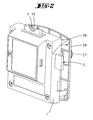
- eine rückwärtige perspektivische Darstellung des Schrankverschlusses,
- Fig. 3
- eine Stirnseitenansicht des Verschlusses mit angedeuteter Schranktür,
- Fig. 4
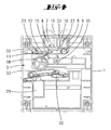
- das Schlosseingerichte im Gehäuse bei zurückgezogenem Riegel und nicht eingesteckter Münze,
- Fig. 5
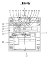
- eine Darstellung gemäß
Fig. 4 mit eingesteckter passender Münze, - Fig. 6
- eine Darstellung gemäß
Fig. 4 mit aktiviertem Blockierelement, - Fig. 7
- eine vergrößerte Darstellung des Ausschnittes VII in
Fig. 6 ,
- Fig. 8
- eine Einzeldarstellung der Abtastvorrichtung,
- Fig. 9
- einen Schnitt gemäß der Linie IX - IX, und
- Fig. 10
- den Riegel in einer perspektivischen Darstellung.
- Fig. 1
- in a perspective front view of the housing and front panel of a cabinet closure in a perspective view,
- Fig. 2
- a rear perspective view of the cabinet closure,
- Fig. 3
- an end view of the closure with indicated cabinet door,
- Fig. 4
- the lock in the case with the latch and the coin not inserted,
- Fig. 5
- a representation according to
Fig. 4 with inserted matching coin, - Fig. 6
- a representation according to
Fig. 4 with activated blocking element, - Fig. 7
- an enlarged view of the section VII in
Fig. 6 .
- Fig. 8
- a single representation of the scanning device,
- Fig. 9
- a section along the line IX - IX, and
- Fig. 10
- the bolt in a perspective view.
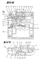
Der in den Zeichnungen darstellte Schrankverschluss kann an einer Schranktür 25 befestigt werden. Er besitzt ein Gehäuse 1, welches schrankinnenseitig an der Schranktür 25 befestigt werden kann. Der Verschluss besitzt eine Frontplatte 26, die auf der Türaußenseite befestigbar ist. Die Frontplatte 26 besitzt eine Handhabe 27, mit der ein Kurbelzapfen 35 verschwenkt werden kann, um einen im Gehäuse 1 angeordneten Riegel 3 in eine Riegelverlagerungsrichtung zu verlagern. Die Frontplatte 26 besitzt darüber hinaus ein Tastenfeld 28, um damit einen Zahlencode einzugeben.The illustrated in the drawings cabinet lock can be attached to a
In der Frontplatte 26 oder in der Handhabe 27 kann auch eine Transponderleseeinrichtung angeordnet sein, um einen Transponder auszulesen. Der Verschluss kann darüber hinaus auch mit einer Fingerabdruckleseeinrichtung verbunden sein.In the
Das Gehäuse 1 besteht aus Kunststoff. Der Riegel 3 ist bevorzugt aus Metall. An der Unterseite des Riegels befindet sich ein Sperrschlitz 30, der zwei Sperrstufen 31, 34 ausbildet. In den Sperrschlitz 30 greift ein Sperrfortsatz 32 eines Sperrhebels 33 ein. Der Sperrhebel 33 kann mittels eines Elektromagneten 29 verschwenkt werden. Er kann eine Sperrstellung einnehmen, in der der Sperrfortsatz 32 bei vorgeschlossenem Riegel vor der Sperrstufe 31 liegt, so dass der vorgeschlossene Riegel von der Handhabe 27 nicht zurückschließbar ist. Alternativ zur Handhabebetätigung kann der Riegel aber auch in Riegelrückzugsrichtung von einer Druck- oder Zugfeder beaufschlagt sein, so dass eine ledigliche Verlagerung des Sperrhebels 33 von der Sperrstellung in eine Freigabestellung erforderlich ist, um den Riegel 3 von einer Riegelvortrittsstellung wieder zurückzuziehen. Um den Riegel vorzuschließen, muss der Kurbelzapfen 35, der in eine Aussparung des Riegels 3 eingreift, gedreht werden. Der Sperrschlitz 30 bildet eine zusätzliche Sperrstufe 34 aus. Vor dieser Sperrstufe 34 kann der Sperrfortsatz 32 in der rückgeschlossenen Riegelstellung liegen, um den Riegel 3 gegen ein Vorschließen zu sperren.The
Auf der im eingebauten Zustand nach oben weisenden Schmalseite des Gehäuses 1 befindet sich ein von aus der Schmalseite herausragenden Schachtwänden flankierter Einsteckschacht 4 für eine Münze 5. Die Randkante des Einsteckschachtes 4 verläuft im Bereich der Längsseiten des Einsteckschachtes 4 bogenförmig und bildet eine Ausbuchtung 19 aus. Diese erstreckt sich nahezu bis zur Gehäuseschmalseite. Die Ausbuchtung 19 ist groß genug, um eine im Einsteckschacht 4 steckende Münze 5 bereichsweise zwischen zwei Fingern zu halten.On the narrow side of the
Der Einsteckschacht 4 wird von zwei Schachtwandungen 22, 23 ausgebildet, wobei sich eine rückwärtige Schachtwand 22 über die gesamte Breitfläche des Einsteckschachtes 4 erstreckt. Die frontseitige Schachtwand 23 erstreckt sich lediglich über einen Teilbereich der Breitseite des Einsteckschachtes 4 und bildet einen Münzeinsteckbegrenzungssteg 24 aus. An diesem Steg 24, welcher den Boden des Einsteckschachtes 4 bildet, liegt die Münze 5 in vollständig eingesteckter Stellung an. In dieser Stellung liegt ein Teilbereich der Münze 5 innerhalb der Ausbuchtung 19. Der Scheitel der aus dem Gehäuse 1 herausragenden Münze liegt dabei außerhalb der gedachten Einsteckschachtrandkante.The
Auf der Schachtwand 22 ist eine Haltebacke 8 befestigt. Die Haltebacke 8 ist mit Schrauben an der Schachtwand 22 derart befestigt, dass sie lageverstellt werden kann.On the
Der festen Haltebacke 8 liegt quer zur Münzeinsteckrichtung eine bewegliche Haltebacke 7 gegenüber. Beide Haltebacken 7, 8 sind in der Lage, die Münze 5 derart teilzuumfassen, dass sie gegen ein Herausziehen aus dem Einsteckschacht 4 formschlüssig gesichert ist. Die Münze 5 ist deshalb in einem Umfangsbereich, der > 180° ist, gefesselt.The fixed holding
Die bewegliche Haltebacke 7 ist einer Schwinge 6 zugeordnet. Die Schwinge 6 ist T-förmig gestaltet. Die beiden T-Schenkel bilden einen Lagerschenkel 10 bzw. eine Führungsnut 12 aus. Der T-Steg bildet die besagte bewegliche Haltebacke 7 aus.The
Während sich die Haltebacke 7 im wesentlichen in Parallelrichtung zur Münzeinsteckrichtung und somit im wesentlichen quer zum Lagerschenkel 10 erstreckt, erstreckt sich der Lagerschenkel 10 im wesentlichen parallel zur Verlagerungsrichtung des Riegels 3. An seinem den Knotenpunkt der Schwinge 6 abgewandten Ende ist der Lagerschenkel 10 mittels einer Schwenkachse 9 am Gehäuse bzw. an der Schachtwand 22 befestigt.While the holding
Im Knotenpunkt der Schwinge 6 befindet sich eine im wesentlichen rechteckige Rippenstruktur. Die Rippen 13, 14, 15, 16 und 17 umrahmen bis auf eine Tourenausnehmung 11 einen im wesentlichen rechteckigen Freiraum, in den ein Tourenstift 18 des Riegels 3 eingreift. Die beiden die Tourenausnehmung 11 flankierenden Rippenabschnitte 13, 14 bilden Sperrflanken aus. Die Rippenstruktur setzt sich in Verlagerungsrichtung des Riegels 3 hinter der Tourenausnehmung 11 fort und bildet eine Führungsnut 12 für den Tourenstift 18.In the node of the
Der Tourenstift 18 wird von einem rechteckigen Abschnitt des Riegels 3 ausgebildet, der über die Rückseite des Riegels 3 vorsteht. An der entsprechenden Stelle ragt über die Frontseite des Riegels 3 ein runder Zapfen. Der Tourenstift 18 liegt auf der gegenüberliegenden Seite des Sperrschlitzes 30 und ist einem Fortsatz des Riegels 3 zugeordnet.The touring
Vor der Öffnung der Führungsnut 12 ist im Gehäuse 1 ein Blockierglied 20 angeordnet. Dieses kann mit einem nadelförmigen Werkzeug 37, welches in eine Gehäuseöffnung 36 eingeführt wird, ortsverlagert werden. Mit einer nicht dargestellten Schraube kann es ortsfixiert werden. Das Blockierelement 20 besitzt einen Blockierzapfen 21, der in die Führungsnut 12 eingesteckt werden kann, um so die Schwinge 6 in einer Position zu fixieren, in der die Tourenausnehmung 11 in der Bewegungsbahn des Tourenstiftes 18 liegt. In dieser Stellung kann der Riegel 3 auch bei nicht eingesteckter Münze 5 verlagert werden. Ist das Blockierelement 20 nicht in seiner Blockierstellung über eine Schraube oder dergleichen blockiert, so kann der Tourenstift 18 bei vollständig vorgeschlossenem Riegel 3 den Blockierzapfen 21 aus der Führungsnut 12 wieder herausdrängen.Before the opening of the
Die Schwinge 6 ist von einer nicht dargestellten Zug- oder Druckfeder derart federbeaufschlagt, dass bei nicht eingesteckter Münze 5 der Tourenstift 18 vor der oberen Sperrflanke 13 liegt. Dies entspricht einer Schwenkstellung der Schwinge 6, in welcher die bewegliche Haltebacke 7 einer zur festen Haltebacke 8 nächst gelegene Stellung einnimmt. In dieser Stellung kann der Riegel 3 nicht vorgeschlossen werden, da der Tourenstift 18 nicht in die Tourenausnehmung 11 eintreten kann, sondern gegen die Sperrflanke 14 läuft, wenn der Riegel 3 verschoben werden soll.The
Um den Verschluss verschließen zu können, muss zunächst eine Münze 5 in den Einsteckschacht 4 eingesteckt werden. Die Münze 5 wird dabei vollständig in den Einsteckschacht 4 eingesteckt, bis sie an dem Schachtboden 24 anliegt. In diesem Zustand liegt noch ein ausreichend großer Teilabschnitt der Münze 5 außerhalb des Einsteckschachtes 4 bzw. in der Ausbuchtung 19, so dass die Münze 5 durch Angriff mit zwei Fingern aus dem Einsteckschacht 4 wieder herausgezogen werden kann.To be able to close the closure, a
Im Zuge des Einsteckens der Münze 5 in den Einsteckschacht 4 werden die beiden Haltebacken 7, 8 durch Verlagerung der beweglichen Haltebacke 7 zunächst auseinandergespreizt, um sich dann geringfügig wieder anzunähern, bis die Münze 5 formschlüssig durch Teilumgriff gehalten ist. Hat die Münze 5 den richtigen Durchmesser, so liegt die Tourenausnehmung 11 in der Bewegungsbahn des Tourenstiftes 18. Bei freigegebenem Sperrhebel 33 kann der Riegel 3 durch Betätigen der Handhabe 27 vorgeschlossen werden. Dabei taucht der Tourenstift 18 durch die Tourenausnehmung 11 und tritt in die von zwei Rippen flankierte Führungsnut 12 ein. Sobald der Tourenstift 18 in die Führungsnut 12 eingetaucht ist, kann die Schwinge 6 nicht mehr verschwenkt werden. Die Münze 5 ist somit im Einsteckschacht 4 zwischen den beiden Haltebacken 7, 8 gefesselt. Der Riegel 3 kann bis in seine Endstellung vorgeschlossen werden, in welcher der Sperrfortsatz 32 hinter die Sperrstufe 31 tritt, um so den Riegel 3 in der Vortrittsstellung zu halten. Der Riegelrückzug erfolgt bevorzugt über eine nicht dargestellte Zugfeder, wie es in der
Wird in den Einsteckschacht 4 eine Münze 5 eingesteckt, die einen kleineren Durchmesser besitzt, so liegt bei eingesteckter Münze 5 der Tourenstift 18 vor der Sperrflanke 13. Der Riegelvorschub ist gesperrt. Wird in den Einsteckschacht 4 eine Münze 5 mit einem zu großen Durchmesser eingesteckt, so liegt bei vollständig eingesteckter Münze der Tourenstift 18 vor der unteren Sperrflanke 14. Der Riegel 3 kann auch in dieser Position nicht verlagert werden.If a
Die Haltebacke 7 weist eine Schraubeneindreh-Öffnung auf. Wird in diese Schraubeneindreh-Öffnung eine Schraube eingedreht, so ist die Verschwenkbarkeit der Schwinge 6 blockiert. Die Schraubeneindreh-Öffnung der Haltebacke 7 fluchtet bevorzugt mit einer Gewindeöffnung der Schachtwandung 23. Die Gewindeöffnung ist derartig positioniert, dass im verschraubten Zustand die Schwinge, die in
In einem nicht dargestellten Ausführungsbeispiel besitzt die Abtastvorrichtung 7, 8 einen Taster oder einen Mikroschalter. Der Taster kann von der Schwinge betätigt werden. Bevorzugt ist der Taster so angeordnet, dass er einen Stromkreis schließt, wenn die Schwinge ihre in
In einem weiteren nicht dargestellten Ausführungsbeispiel ist vorgesehen, dass eine Schaltfahne eines Tasters oder eines Schalters unmittelbar die Münze abtastet, um so ein elektrisches Abtastsignal zu liefern.In a further embodiment, not shown, it is provided that a switching flag of a button or a switch directly scans the coin, so as to provide an electrical scanning signal.
Claims (16)
- Locker lock comprising a housing (1) and a bolt (3) arranged therein which can be displaced by actuating a handle (2), comprising an insertion slot (4) for inserting a coin (5), comprising a gauging device (7, 8) for gauging the diameter of the coin (5) inserted through the insertion slot (4) and into a gauging position, the gauging device (7, 8) cooperating with a barring apparatus (13, 14, 18) in such a way that the bolt (3) can be displaced only when a coin (5) has a suitable diameter, characterised in that the gauging device (7, 8) forms a holding clamp (7) which grips the coin (5) that is in the insertion slot (4) such that the coin, which in some regions is accessible from the outside when in the gauging position, cannot be removed when the bolt (3) is locked.
- Locker lock according to claim 1, characterised in that the holding clamp (7) is formed by an oscillating link (6) which is mounted pivotally about a pin (9) which is fixed with respect to a housing.
- Locker lock according to one or more of the preceding claims, characterised in that the oscillating link (6) forms a bearing arm (10), on the end of which the pin (9) is arranged and from which the holding clamp (7) projects downwards in a substantially transverse manner.
- Locker lock according to one or more of the preceding claims, characterised in that the oscillating link (6) forms a rotation recess (11), flanked by at least one barring flank (13, 14), for admitting a rotation peg (18) associated with the bolt (3).
- Locker lock according to one or more of the preceding claims, characterised in that the bearing arm (10) and a guide groove (12) connected to the rotation recess (11) extend substantially parallel to the bolt displacement direction.
- Locker lock according to one or more of the preceding claims, characterised by a stationary holding clamp (8) opposite the pivotable holding clamp (7).
- Locker lock according to one or more of the preceding claims, characterised in that the distance between the two holding clamps (7, 8) can be adjusted by changing the location of the stationary holding clamp (8).
- Locker lock according to one or more of the preceding claims, characterised in that the insertion slot (4) has a protrusion (19) in which a portion of the inserted coin (5) is located.
- Locker lock according to one or more of the preceding claims, characterised by a barring device (31, 32) which holds the bolt (3) against a bolt displacement in the re-locked bolt position independently of the barring apparatus (13, 14, 18), and which may be released by a release device (29).
- Locker lock according to one or more of the preceding claims, characterised in that the release device (29) releases the barring device (31, 32) only after a secret code has been entered.
- Locker lock according to one or more of the preceding claims, characterised in that the secret code can be detected by a transponder call-up apparatus, a touch screen apparatus, a cylinder lock or a keyboard.
- Locker lock according to one or more of the preceding claims, characterised by a fine function in the event of which the locker lock is opened by means of an overriding secret code, in particular a closing code, the coin (5) can be removed and the locker lock closed again, bypassing the gauging function.
- Locker lock according to one or more of the preceding claims, characterised by an auxiliary tool by means of which the gauging device (7, 8) can be moved into a position corresponding to that of the coin (5) inserted in the insertion slot (4), and comprising a blocking element (20) which blocks the gauging device (7, 8) in a position which can displace the bolt (3).
- Locker lock according to one or more of the preceding claims, characterised by a blocking spigot (21) which is formed by the blocking element (20) and can engage in a guide groove (12) of the oscillating link (6) in order to block the oscillating link (6) in a pivot position in which the bolt (3) can be pre-locked.
- Locker lock according to one or more of the preceding claims, characterised in that the oscillating link (6) can be fixed by a screw.
- Locker lock according to one or more of the preceding claims, characterised by a switch or button associated with the gauging device (7, 8) for providing an electrical signal with which the displacement movement of the bolt (3) can be blocked when no coin has been inserted or when an unsuitable coin (5) has been inserted.
Applications Claiming Priority (1)
| Application Number | Priority Date | Filing Date | Title |
|---|---|---|---|
| DE200710052583 DE102007052583A1 (en) | 2007-10-29 | 2007-10-29 | Münzpfandschrankverschluss |
Publications (3)
| Publication Number | Publication Date |
|---|---|
| EP2055871A2 EP2055871A2 (en) | 2009-05-06 |
| EP2055871A3 EP2055871A3 (en) | 2010-08-04 |
| EP2055871B1 true EP2055871B1 (en) | 2012-06-20 |
Family
ID=40130903
Family Applications (1)
| Application Number | Title | Priority Date | Filing Date |
|---|---|---|---|
| EP20080167517 Not-in-force EP2055871B1 (en) | 2007-10-29 | 2008-10-24 | Coin deposit cupboard lock |
Country Status (4)
| Country | Link |
|---|---|
| US (1) | US7748512B2 (en) |
| EP (1) | EP2055871B1 (en) |
| DE (1) | DE102007052583A1 (en) |
| ES (1) | ES2389522T3 (en) |
Cited By (1)
| Publication number | Priority date | Publication date | Assignee | Title |
|---|---|---|---|---|
| DE102017113463B3 (en) | 2017-06-20 | 2018-07-12 | W&F Locks Ohg | Cam lock |
Families Citing this family (2)
| Publication number | Priority date | Publication date | Assignee | Title |
|---|---|---|---|---|
| SE532298C2 (en) * | 2008-04-16 | 2009-12-08 | Jokab Safety Ab | Locking |
| DE102015113243B4 (en) | 2015-08-11 | 2023-10-12 | Schulte-Schlagbaum Aktiengesellschaft | Cabinet door lock that communicates wirelessly with a central unit |
Family Cites Families (10)
| Publication number | Priority date | Publication date | Assignee | Title |
|---|---|---|---|---|
| US1633411A (en) * | 1925-12-29 | 1927-06-21 | Frederick W Kassler | Coin-controlled lock |
| US2034359A (en) * | 1934-06-07 | 1936-03-17 | Isaac J Segal | Lock |
| DE3242045A1 (en) * | 1982-11-13 | 1984-05-17 | Schulte-Schlagbaum Ag, 5620 Velbert | CASTLE, IN PARTICULAR PAYLOCK |
| US5573098A (en) * | 1995-03-01 | 1996-11-12 | Minnesota Lock, Inc. | Card-activated lock mechanism |
| DE19515765A1 (en) | 1995-04-28 | 1996-10-31 | Peter Fuchs | Coin operated lock mechanism for use on shopping trolleys |
| DE19527066C2 (en) | 1995-07-25 | 2002-11-14 | Mauer Gmbh | castle tower |
| DE19832516A1 (en) | 1998-07-20 | 2000-01-27 | Schulte Schlagbaum Ag | Lock, especially for a locking system |
| DE10350951B4 (en) | 2003-10-30 | 2008-02-07 | Schulte-Schlagbaum Ag | Lock with closing function to be operated after coin insertion |
| EP1821267A1 (en) * | 2006-02-09 | 2007-08-22 | Somers Co., Ltd. | A lock structure |
| DE102006034292A1 (en) | 2006-07-21 | 2008-01-24 | Schulte-Schlagbaum Ag | Electronic lock for e.g. personal hotel room safe incorporates activation time limiting device |
-
2007
- 2007-10-29 DE DE200710052583 patent/DE102007052583A1/en not_active Withdrawn
-
2008
- 2008-10-24 EP EP20080167517 patent/EP2055871B1/en not_active Not-in-force
- 2008-10-24 ES ES08167517T patent/ES2389522T3/en active Active
- 2008-11-03 US US12/263,833 patent/US7748512B2/en not_active Expired - Fee Related
Cited By (1)
| Publication number | Priority date | Publication date | Assignee | Title |
|---|---|---|---|---|
| DE102017113463B3 (en) | 2017-06-20 | 2018-07-12 | W&F Locks Ohg | Cam lock |
Also Published As
| Publication number | Publication date |
|---|---|
| EP2055871A2 (en) | 2009-05-06 |
| ES2389522T3 (en) | 2012-10-26 |
| EP2055871A3 (en) | 2010-08-04 |
| US7748512B2 (en) | 2010-07-06 |
| DE102007052583A1 (en) | 2009-04-30 |
| US20090113951A1 (en) | 2009-05-07 |
Similar Documents
| Publication | Publication Date | Title |
|---|---|---|
| DE19701761C1 (en) | Self-locking lock for door | |
| EP2703586B1 (en) | Passive wing locking device with a sensor device | |
| EP1447500B1 (en) | Security blocking device | |
| DE102008011551B4 (en) | Self-locking additional locking | |
| DE102005015248B4 (en) | Grand piano lock with an electric door opener | |
| DE60308825T2 (en) | SAFETY STORAGE DEVICE | |
| EP3299550A1 (en) | Electric door opener for swing door with magnetic bolt | |
| EP0410122B1 (en) | Mortise lock with catch bolt fixing device | |
| DE10194835B4 (en) | lever lock | |
| EP2055871B1 (en) | Coin deposit cupboard lock | |
| DE3926132C2 (en) | ||
| DE202021101478U1 (en) | Trap for a door lock and a door lock with such a trap | |
| DE102006005996A1 (en) | Door connection with electrical door opener for mechanically self-adjusted multiple locking device, has multiple locking, with hub, bolt, relapses into locking position with opened door, without obstructing tilting movement of door | |
| DE3124180C2 (en) | ||
| EP0799956A2 (en) | Lock | |
| DE10350951B4 (en) | Lock with closing function to be operated after coin insertion | |
| DE3801672C2 (en) | ||
| DE202009007674U1 (en) | Espagnolette lock with multiple locking | |
| DE202007016091U1 (en) | Espagnolette | |
| EP1156180B1 (en) | Lock with increased bolt shot and with an anti-panic function | |
| DE280390C (en) | ||
| DE102012111537A1 (en) | Lock with a releasable turntable | |
| EP1699023A2 (en) | Coin lock | |
| DE102008016317B4 (en) | Lock with a case rotation arrangement | |
| DE102004037159B4 (en) | cash drawer |
Legal Events
| Date | Code | Title | Description |
|---|---|---|---|
| PUAI | Public reference made under article 153(3) epc to a published international application that has entered the european phase |
Free format text: ORIGINAL CODE: 0009012 |
|
| AK | Designated contracting states |
Kind code of ref document: A2 Designated state(s): AT BE BG CH CY CZ DE DK EE ES FI FR GB GR HR HU IE IS IT LI LT LU LV MC MT NL NO PL PT RO SE SI SK TR |
|
| AX | Request for extension of the european patent |
Extension state: AL BA MK RS |
|
| PUAL | Search report despatched |
Free format text: ORIGINAL CODE: 0009013 |
|
| AK | Designated contracting states |
Kind code of ref document: A3 Designated state(s): AT BE BG CH CY CZ DE DK EE ES FI FR GB GR HR HU IE IS IT LI LT LU LV MC MT NL NO PL PT RO SE SI SK TR |
|
| AX | Request for extension of the european patent |
Extension state: AL BA MK RS |
|
| RIC1 | Information provided on ipc code assigned before grant |
Ipc: E05B 47/00 20060101AFI20081230BHEP Ipc: G07C 9/00 20060101ALI20100630BHEP Ipc: E05B 47/06 20060101ALI20100630BHEP |
|
| 17P | Request for examination filed |
Effective date: 20110128 |
|
| AKX | Designation fees paid |
Designated state(s): AT BE BG CH CY CZ DE DK EE ES FI FR GB GR HR HU IE IS IT LI LT LU LV MC MT NL NO PL PT RO SE SI SK TR |
|
| RIC1 | Information provided on ipc code assigned before grant |
Ipc: E05B 47/00 20060101AFI20111228BHEP Ipc: E05B 47/06 20060101ALI20111228BHEP Ipc: G07C 9/00 20060101ALI20111228BHEP |
|
| GRAP | Despatch of communication of intention to grant a patent |
Free format text: ORIGINAL CODE: EPIDOSNIGR1 |
|
| GRAS | Grant fee paid |
Free format text: ORIGINAL CODE: EPIDOSNIGR3 |
|
| GRAA | (expected) grant |
Free format text: ORIGINAL CODE: 0009210 |
|
| AK | Designated contracting states |
Kind code of ref document: B1 Designated state(s): AT BE BG CH CY CZ DE DK EE ES FI FR GB GR HR HU IE IS IT LI LT LU LV MC MT NL NO PL PT RO SE SI SK TR |
|
| REG | Reference to a national code |
Ref country code: GB Ref legal event code: FG4D Free format text: NOT ENGLISH |
|
| REG | Reference to a national code |
Ref country code: CH Ref legal event code: EP |
|
| REG | Reference to a national code |
Ref country code: AT Ref legal event code: REF Ref document number: 563188 Country of ref document: AT Kind code of ref document: T Effective date: 20120715 |
|
| REG | Reference to a national code |
Ref country code: IE Ref legal event code: FG4D Free format text: LANGUAGE OF EP DOCUMENT: GERMAN |
|
| REG | Reference to a national code |
Ref country code: CH Ref legal event code: NV Representative=s name: R. A. EGLI & CO. PATENTANWAELTE |
|
| REG | Reference to a national code |
Ref country code: DE Ref legal event code: R096 Ref document number: 502008007468 Country of ref document: DE Effective date: 20120816 |
|
| REG | Reference to a national code |
Ref country code: NL Ref legal event code: T3 |
|
| REG | Reference to a national code |
Ref country code: SE Ref legal event code: TRGR |
|
| REG | Reference to a national code |
Ref country code: ES Ref legal event code: FG2A Ref document number: 2389522 Country of ref document: ES Kind code of ref document: T3 Effective date: 20121026 |
|
| PG25 | Lapsed in a contracting state [announced via postgrant information from national office to epo] |
Ref country code: LT Free format text: LAPSE BECAUSE OF FAILURE TO SUBMIT A TRANSLATION OF THE DESCRIPTION OR TO PAY THE FEE WITHIN THE PRESCRIBED TIME-LIMIT Effective date: 20120620 Ref country code: FI Free format text: LAPSE BECAUSE OF FAILURE TO SUBMIT A TRANSLATION OF THE DESCRIPTION OR TO PAY THE FEE WITHIN THE PRESCRIBED TIME-LIMIT Effective date: 20120620 Ref country code: NO Free format text: LAPSE BECAUSE OF FAILURE TO SUBMIT A TRANSLATION OF THE DESCRIPTION OR TO PAY THE FEE WITHIN THE PRESCRIBED TIME-LIMIT Effective date: 20120920 |
|
| REG | Reference to a national code |
Ref country code: LT Ref legal event code: MG4D Effective date: 20120620 |
|
| PG25 | Lapsed in a contracting state [announced via postgrant information from national office to epo] |
Ref country code: SI Free format text: LAPSE BECAUSE OF FAILURE TO SUBMIT A TRANSLATION OF THE DESCRIPTION OR TO PAY THE FEE WITHIN THE PRESCRIBED TIME-LIMIT Effective date: 20120620 Ref country code: GR Free format text: LAPSE BECAUSE OF FAILURE TO SUBMIT A TRANSLATION OF THE DESCRIPTION OR TO PAY THE FEE WITHIN THE PRESCRIBED TIME-LIMIT Effective date: 20120921 Ref country code: HR Free format text: LAPSE BECAUSE OF FAILURE TO SUBMIT A TRANSLATION OF THE DESCRIPTION OR TO PAY THE FEE WITHIN THE PRESCRIBED TIME-LIMIT Effective date: 20120620 Ref country code: LV Free format text: LAPSE BECAUSE OF FAILURE TO SUBMIT A TRANSLATION OF THE DESCRIPTION OR TO PAY THE FEE WITHIN THE PRESCRIBED TIME-LIMIT Effective date: 20120620 |
|
| PG25 | Lapsed in a contracting state [announced via postgrant information from national office to epo] |
Ref country code: SK Free format text: LAPSE BECAUSE OF FAILURE TO SUBMIT A TRANSLATION OF THE DESCRIPTION OR TO PAY THE FEE WITHIN THE PRESCRIBED TIME-LIMIT Effective date: 20120620 Ref country code: EE Free format text: LAPSE BECAUSE OF FAILURE TO SUBMIT A TRANSLATION OF THE DESCRIPTION OR TO PAY THE FEE WITHIN THE PRESCRIBED TIME-LIMIT Effective date: 20120620 Ref country code: CY Free format text: LAPSE BECAUSE OF FAILURE TO SUBMIT A TRANSLATION OF THE DESCRIPTION OR TO PAY THE FEE WITHIN THE PRESCRIBED TIME-LIMIT Effective date: 20120620 Ref country code: CZ Free format text: LAPSE BECAUSE OF FAILURE TO SUBMIT A TRANSLATION OF THE DESCRIPTION OR TO PAY THE FEE WITHIN THE PRESCRIBED TIME-LIMIT Effective date: 20120620 Ref country code: IS Free format text: LAPSE BECAUSE OF FAILURE TO SUBMIT A TRANSLATION OF THE DESCRIPTION OR TO PAY THE FEE WITHIN THE PRESCRIBED TIME-LIMIT Effective date: 20121020 Ref country code: RO Free format text: LAPSE BECAUSE OF FAILURE TO SUBMIT A TRANSLATION OF THE DESCRIPTION OR TO PAY THE FEE WITHIN THE PRESCRIBED TIME-LIMIT Effective date: 20120620 |
|
| PG25 | Lapsed in a contracting state [announced via postgrant information from national office to epo] |
Ref country code: IT Free format text: LAPSE BECAUSE OF FAILURE TO SUBMIT A TRANSLATION OF THE DESCRIPTION OR TO PAY THE FEE WITHIN THE PRESCRIBED TIME-LIMIT Effective date: 20120620 Ref country code: PT Free format text: LAPSE BECAUSE OF FAILURE TO SUBMIT A TRANSLATION OF THE DESCRIPTION OR TO PAY THE FEE WITHIN THE PRESCRIBED TIME-LIMIT Effective date: 20121022 Ref country code: PL Free format text: LAPSE BECAUSE OF FAILURE TO SUBMIT A TRANSLATION OF THE DESCRIPTION OR TO PAY THE FEE WITHIN THE PRESCRIBED TIME-LIMIT Effective date: 20120620 |
|
| PLBE | No opposition filed within time limit |
Free format text: ORIGINAL CODE: 0009261 |
|
| STAA | Information on the status of an ep patent application or granted ep patent |
Free format text: STATUS: NO OPPOSITION FILED WITHIN TIME LIMIT |
|
| PG25 | Lapsed in a contracting state [announced via postgrant information from national office to epo] |
Ref country code: DK Free format text: LAPSE BECAUSE OF FAILURE TO SUBMIT A TRANSLATION OF THE DESCRIPTION OR TO PAY THE FEE WITHIN THE PRESCRIBED TIME-LIMIT Effective date: 20120620 |
|
| 26N | No opposition filed |
Effective date: 20130321 |
|
| PG25 | Lapsed in a contracting state [announced via postgrant information from national office to epo] |
Ref country code: MC Free format text: LAPSE BECAUSE OF NON-PAYMENT OF DUE FEES Effective date: 20121031 |
|
| REG | Reference to a national code |
Ref country code: DE Ref legal event code: R097 Ref document number: 502008007468 Country of ref document: DE Effective date: 20130321 |
|
| REG | Reference to a national code |
Ref country code: IE Ref legal event code: MM4A |
|
| PG25 | Lapsed in a contracting state [announced via postgrant information from national office to epo] |
Ref country code: BG Free format text: LAPSE BECAUSE OF FAILURE TO SUBMIT A TRANSLATION OF THE DESCRIPTION OR TO PAY THE FEE WITHIN THE PRESCRIBED TIME-LIMIT Effective date: 20120920 Ref country code: IE Free format text: LAPSE BECAUSE OF NON-PAYMENT OF DUE FEES Effective date: 20121024 |
|
| PG25 | Lapsed in a contracting state [announced via postgrant information from national office to epo] |
Ref country code: MT Free format text: LAPSE BECAUSE OF FAILURE TO SUBMIT A TRANSLATION OF THE DESCRIPTION OR TO PAY THE FEE WITHIN THE PRESCRIBED TIME-LIMIT Effective date: 20120620 |
|
| PG25 | Lapsed in a contracting state [announced via postgrant information from national office to epo] |
Ref country code: TR Free format text: LAPSE BECAUSE OF FAILURE TO SUBMIT A TRANSLATION OF THE DESCRIPTION OR TO PAY THE FEE WITHIN THE PRESCRIBED TIME-LIMIT Effective date: 20120620 |
|
| PG25 | Lapsed in a contracting state [announced via postgrant information from national office to epo] |
Ref country code: LU Free format text: LAPSE BECAUSE OF NON-PAYMENT OF DUE FEES Effective date: 20121024 |
|
| PG25 | Lapsed in a contracting state [announced via postgrant information from national office to epo] |
Ref country code: HU Free format text: LAPSE BECAUSE OF FAILURE TO SUBMIT A TRANSLATION OF THE DESCRIPTION OR TO PAY THE FEE WITHIN THE PRESCRIBED TIME-LIMIT Effective date: 20081024 |
|
| PGFP | Annual fee paid to national office [announced via postgrant information from national office to epo] |
Ref country code: ES Payment date: 20141009 Year of fee payment: 7 Ref country code: GB Payment date: 20141013 Year of fee payment: 7 Ref country code: CH Payment date: 20141013 Year of fee payment: 7 Ref country code: SE Payment date: 20141013 Year of fee payment: 7 Ref country code: FR Payment date: 20141008 Year of fee payment: 7 |
|
| PGFP | Annual fee paid to national office [announced via postgrant information from national office to epo] |
Ref country code: NL Payment date: 20141009 Year of fee payment: 7 Ref country code: AT Payment date: 20141009 Year of fee payment: 7 |
|
| PGFP | Annual fee paid to national office [announced via postgrant information from national office to epo] |
Ref country code: BE Payment date: 20141020 Year of fee payment: 7 |
|
| REG | Reference to a national code |
Ref country code: SE Ref legal event code: EUG Ref country code: CH Ref legal event code: PL |
|
| REG | Reference to a national code |
Ref country code: AT Ref legal event code: MM01 Ref document number: 563188 Country of ref document: AT Kind code of ref document: T Effective date: 20151024 |
|
| GBPC | Gb: european patent ceased through non-payment of renewal fee |
Effective date: 20151024 |
|
| REG | Reference to a national code |
Ref country code: NL Ref legal event code: MM Effective date: 20151101 |
|
| PG25 | Lapsed in a contracting state [announced via postgrant information from national office to epo] |
Ref country code: LI Free format text: LAPSE BECAUSE OF NON-PAYMENT OF DUE FEES Effective date: 20151031 Ref country code: CH Free format text: LAPSE BECAUSE OF NON-PAYMENT OF DUE FEES Effective date: 20151031 Ref country code: GB Free format text: LAPSE BECAUSE OF NON-PAYMENT OF DUE FEES Effective date: 20151024 |
|
| REG | Reference to a national code |
Ref country code: FR Ref legal event code: ST Effective date: 20160630 |
|
| PG25 | Lapsed in a contracting state [announced via postgrant information from national office to epo] |
Ref country code: NL Free format text: LAPSE BECAUSE OF NON-PAYMENT OF DUE FEES Effective date: 20151101 Ref country code: AT Free format text: LAPSE BECAUSE OF NON-PAYMENT OF DUE FEES Effective date: 20151024 Ref country code: SE Free format text: LAPSE BECAUSE OF NON-PAYMENT OF DUE FEES Effective date: 20151025 Ref country code: FR Free format text: LAPSE BECAUSE OF NON-PAYMENT OF DUE FEES Effective date: 20151102 |
|
| PG25 | Lapsed in a contracting state [announced via postgrant information from national office to epo] |
Ref country code: ES Free format text: LAPSE BECAUSE OF NON-PAYMENT OF DUE FEES Effective date: 20151025 |
|
| PG25 | Lapsed in a contracting state [announced via postgrant information from national office to epo] |
Ref country code: BE Free format text: LAPSE BECAUSE OF NON-PAYMENT OF DUE FEES Effective date: 20151031 |
|
| PGFP | Annual fee paid to national office [announced via postgrant information from national office to epo] |
Ref country code: DE Payment date: 20171016 Year of fee payment: 10 |
|
| REG | Reference to a national code |
Ref country code: DE Ref legal event code: R119 Ref document number: 502008007468 Country of ref document: DE |
|
| PG25 | Lapsed in a contracting state [announced via postgrant information from national office to epo] |
Ref country code: DE Free format text: LAPSE BECAUSE OF NON-PAYMENT OF DUE FEES Effective date: 20190501 |