EP2055688A2 - Process and apparatus for producing a ceramic material - Google Patents
Process and apparatus for producing a ceramic material Download PDFInfo
- Publication number
- EP2055688A2 EP2055688A2 EP08018999A EP08018999A EP2055688A2 EP 2055688 A2 EP2055688 A2 EP 2055688A2 EP 08018999 A EP08018999 A EP 08018999A EP 08018999 A EP08018999 A EP 08018999A EP 2055688 A2 EP2055688 A2 EP 2055688A2
- Authority
- EP
- European Patent Office
- Prior art keywords
- mask
- substrate
- aerosol
- raw material
- material particles
- Prior art date
- Legal status (The legal status is an assumption and is not a legal conclusion. Google has not performed a legal analysis and makes no representation as to the accuracy of the status listed.)
- Withdrawn
Links
- 229910010293 ceramic material Inorganic materials 0.000 title claims abstract description 21
- 238000000034 method Methods 0.000 title claims description 22
- 239000000758 substrate Substances 0.000 claims abstract description 87
- 239000002245 particle Substances 0.000 claims abstract description 66
- 239000000443 aerosol Substances 0.000 claims abstract description 48
- 239000002994 raw material Substances 0.000 claims abstract description 48
- 239000012159 carrier gas Substances 0.000 claims abstract description 22
- 238000010304 firing Methods 0.000 claims description 9
- 239000011230 binding agent Substances 0.000 abstract description 13
- 238000000465 moulding Methods 0.000 description 33
- 239000004642 Polyimide Substances 0.000 description 15
- 229920001721 polyimide Polymers 0.000 description 15
- 229910052451 lead zirconate titanate Inorganic materials 0.000 description 14
- 239000007789 gas Substances 0.000 description 10
- 238000005238 degreasing Methods 0.000 description 5
- 239000000853 adhesive Substances 0.000 description 3
- 230000008602 contraction Effects 0.000 description 3
- 238000009826 distribution Methods 0.000 description 3
- 230000007613 environmental effect Effects 0.000 description 3
- 238000010438 heat treatment Methods 0.000 description 3
- 230000035939 shock Effects 0.000 description 3
- XKRFYHLGVUSROY-UHFFFAOYSA-N Argon Chemical compound [Ar] XKRFYHLGVUSROY-UHFFFAOYSA-N 0.000 description 2
- MCMNRKCIXSYSNV-UHFFFAOYSA-N Zirconium dioxide Chemical compound O=[Zr]=O MCMNRKCIXSYSNV-UHFFFAOYSA-N 0.000 description 2
- 230000015572 biosynthetic process Effects 0.000 description 2
- 238000005056 compaction Methods 0.000 description 2
- 230000008021 deposition Effects 0.000 description 2
- 239000011361 granulated particle Substances 0.000 description 2
- 238000001746 injection moulding Methods 0.000 description 2
- HFGPZNIAWCZYJU-UHFFFAOYSA-N lead zirconate titanate Chemical compound [O-2].[O-2].[O-2].[O-2].[O-2].[Ti+4].[Zr+4].[Pb+2] HFGPZNIAWCZYJU-UHFFFAOYSA-N 0.000 description 2
- 229910052751 metal Inorganic materials 0.000 description 2
- 239000002184 metal Substances 0.000 description 2
- 230000000737 periodic effect Effects 0.000 description 2
- 230000002093 peripheral effect Effects 0.000 description 2
- 230000000630 rising effect Effects 0.000 description 2
- 239000007787 solid Substances 0.000 description 2
- 239000000126 substance Substances 0.000 description 2
- 229910052727 yttrium Inorganic materials 0.000 description 2
- 239000004925 Acrylic resin Substances 0.000 description 1
- 229920000178 Acrylic resin Polymers 0.000 description 1
- IJGRMHOSHXDMSA-UHFFFAOYSA-N Atomic nitrogen Chemical compound N#N IJGRMHOSHXDMSA-UHFFFAOYSA-N 0.000 description 1
- OKKJLVBELUTLKV-UHFFFAOYSA-N Methanol Chemical group OC OKKJLVBELUTLKV-UHFFFAOYSA-N 0.000 description 1
- 239000004372 Polyvinyl alcohol Substances 0.000 description 1
- 229910052786 argon Inorganic materials 0.000 description 1
- 239000012298 atmosphere Substances 0.000 description 1
- QVGXLLKOCUKJST-UHFFFAOYSA-N atomic oxygen Chemical compound [O] QVGXLLKOCUKJST-UHFFFAOYSA-N 0.000 description 1
- 229910002113 barium titanate Inorganic materials 0.000 description 1
- 239000003985 ceramic capacitor Substances 0.000 description 1
- 239000012141 concentrate Substances 0.000 description 1
- 238000005336 cracking Methods 0.000 description 1
- 238000007599 discharging Methods 0.000 description 1
- 230000000694 effects Effects 0.000 description 1
- 238000005530 etching Methods 0.000 description 1
- 239000005431 greenhouse gas Substances 0.000 description 1
- 239000001307 helium Substances 0.000 description 1
- 229910052734 helium Inorganic materials 0.000 description 1
- SWQJXJOGLNCZEY-UHFFFAOYSA-N helium atom Chemical compound [He] SWQJXJOGLNCZEY-UHFFFAOYSA-N 0.000 description 1
- 230000010354 integration Effects 0.000 description 1
- 239000000463 material Substances 0.000 description 1
- 229920000609 methyl cellulose Polymers 0.000 description 1
- 239000001923 methylcellulose Substances 0.000 description 1
- 235000010981 methylcellulose Nutrition 0.000 description 1
- 238000002156 mixing Methods 0.000 description 1
- 239000012778 molding material Substances 0.000 description 1
- 239000001301 oxygen Substances 0.000 description 1
- 229910052760 oxygen Inorganic materials 0.000 description 1
- 229920002451 polyvinyl alcohol Polymers 0.000 description 1
- 238000005245 sintering Methods 0.000 description 1
- 229910002076 stabilized zirconia Inorganic materials 0.000 description 1
- 229910001220 stainless steel Inorganic materials 0.000 description 1
- 239000010935 stainless steel Substances 0.000 description 1
- 238000003756 stirring Methods 0.000 description 1
- 230000001629 suppression Effects 0.000 description 1
- VWQVUPCCIRVNHF-UHFFFAOYSA-N yttrium atom Chemical compound [Y] VWQVUPCCIRVNHF-UHFFFAOYSA-N 0.000 description 1
Images




Classifications
-
- C—CHEMISTRY; METALLURGY
- C04—CEMENTS; CONCRETE; ARTIFICIAL STONE; CERAMICS; REFRACTORIES
- C04B—LIME, MAGNESIA; SLAG; CEMENTS; COMPOSITIONS THEREOF, e.g. MORTARS, CONCRETE OR LIKE BUILDING MATERIALS; ARTIFICIAL STONE; CERAMICS; REFRACTORIES; TREATMENT OF NATURAL STONE
- C04B35/00—Shaped ceramic products characterised by their composition; Ceramics compositions; Processing powders of inorganic compounds preparatory to the manufacturing of ceramic products
- C04B35/622—Forming processes; Processing powders of inorganic compounds preparatory to the manufacturing of ceramic products
- C04B35/62218—Forming processes; Processing powders of inorganic compounds preparatory to the manufacturing of ceramic products obtaining ceramic films, e.g. by using temporary supports
-
- C—CHEMISTRY; METALLURGY
- C04—CEMENTS; CONCRETE; ARTIFICIAL STONE; CERAMICS; REFRACTORIES
- C04B—LIME, MAGNESIA; SLAG; CEMENTS; COMPOSITIONS THEREOF, e.g. MORTARS, CONCRETE OR LIKE BUILDING MATERIALS; ARTIFICIAL STONE; CERAMICS; REFRACTORIES; TREATMENT OF NATURAL STONE
- C04B35/00—Shaped ceramic products characterised by their composition; Ceramics compositions; Processing powders of inorganic compounds preparatory to the manufacturing of ceramic products
- C04B35/01—Shaped ceramic products characterised by their composition; Ceramics compositions; Processing powders of inorganic compounds preparatory to the manufacturing of ceramic products based on oxide ceramics
- C04B35/48—Shaped ceramic products characterised by their composition; Ceramics compositions; Processing powders of inorganic compounds preparatory to the manufacturing of ceramic products based on oxide ceramics based on zirconium or hafnium oxides, zirconates, zircon or hafnates
- C04B35/49—Shaped ceramic products characterised by their composition; Ceramics compositions; Processing powders of inorganic compounds preparatory to the manufacturing of ceramic products based on oxide ceramics based on zirconium or hafnium oxides, zirconates, zircon or hafnates containing also titanium oxides or titanates
- C04B35/491—Shaped ceramic products characterised by their composition; Ceramics compositions; Processing powders of inorganic compounds preparatory to the manufacturing of ceramic products based on oxide ceramics based on zirconium or hafnium oxides, zirconates, zircon or hafnates containing also titanium oxides or titanates based on lead zirconates and lead titanates, e.g. PZT
-
- C—CHEMISTRY; METALLURGY
- C04—CEMENTS; CONCRETE; ARTIFICIAL STONE; CERAMICS; REFRACTORIES
- C04B—LIME, MAGNESIA; SLAG; CEMENTS; COMPOSITIONS THEREOF, e.g. MORTARS, CONCRETE OR LIKE BUILDING MATERIALS; ARTIFICIAL STONE; CERAMICS; REFRACTORIES; TREATMENT OF NATURAL STONE
- C04B2235/00—Aspects relating to ceramic starting mixtures or sintered ceramic products
- C04B2235/02—Composition of constituents of the starting material or of secondary phases of the final product
- C04B2235/50—Constituents or additives of the starting mixture chosen for their shape or used because of their shape or their physical appearance
- C04B2235/54—Particle size related information
- C04B2235/5418—Particle size related information expressed by the size of the particles or aggregates thereof
- C04B2235/5436—Particle size related information expressed by the size of the particles or aggregates thereof micrometer sized, i.e. from 1 to 100 micron
-
- C—CHEMISTRY; METALLURGY
- C04—CEMENTS; CONCRETE; ARTIFICIAL STONE; CERAMICS; REFRACTORIES
- C04B—LIME, MAGNESIA; SLAG; CEMENTS; COMPOSITIONS THEREOF, e.g. MORTARS, CONCRETE OR LIKE BUILDING MATERIALS; ARTIFICIAL STONE; CERAMICS; REFRACTORIES; TREATMENT OF NATURAL STONE
- C04B2235/00—Aspects relating to ceramic starting mixtures or sintered ceramic products
- C04B2235/02—Composition of constituents of the starting material or of secondary phases of the final product
- C04B2235/50—Constituents or additives of the starting mixture chosen for their shape or used because of their shape or their physical appearance
- C04B2235/54—Particle size related information
- C04B2235/5418—Particle size related information expressed by the size of the particles or aggregates thereof
- C04B2235/5445—Particle size related information expressed by the size of the particles or aggregates thereof submicron sized, i.e. from 0,1 to 1 micron
-
- C—CHEMISTRY; METALLURGY
- C04—CEMENTS; CONCRETE; ARTIFICIAL STONE; CERAMICS; REFRACTORIES
- C04B—LIME, MAGNESIA; SLAG; CEMENTS; COMPOSITIONS THEREOF, e.g. MORTARS, CONCRETE OR LIKE BUILDING MATERIALS; ARTIFICIAL STONE; CERAMICS; REFRACTORIES; TREATMENT OF NATURAL STONE
- C04B2235/00—Aspects relating to ceramic starting mixtures or sintered ceramic products
- C04B2235/60—Aspects relating to the preparation, properties or mechanical treatment of green bodies or pre-forms
- C04B2235/602—Making the green bodies or pre-forms by moulding
-
- C—CHEMISTRY; METALLURGY
- C04—CEMENTS; CONCRETE; ARTIFICIAL STONE; CERAMICS; REFRACTORIES
- C04B—LIME, MAGNESIA; SLAG; CEMENTS; COMPOSITIONS THEREOF, e.g. MORTARS, CONCRETE OR LIKE BUILDING MATERIALS; ARTIFICIAL STONE; CERAMICS; REFRACTORIES; TREATMENT OF NATURAL STONE
- C04B2235/00—Aspects relating to ceramic starting mixtures or sintered ceramic products
- C04B2235/70—Aspects relating to sintered or melt-casted ceramic products
- C04B2235/94—Products characterised by their shape
Definitions
- This invention relates to a process and apparatus for producing a ceramic material.
- This invention particularly relates to a process and apparatus for producing a ceramic material, wherein aerosolized raw material particles are jetted out and wherein the raw material particles are thereby deposited on a substrate to form a molded body.
- injection molding techniques have been utilized as the techniques for producing ceramic materials.
- injection molding techniques though complicated molded bodies are capable of being molded accurately, mixing proportions of organic binders with respect to molding materials are as high as approximately 50% by weight. Therefore, expansion and contraction differences of the molded bodies at the time of degreasing steps are large. In order for cracking due to the expansion and contraction differences to be prevented, it is necessary to perform the degreasing steps for a long period of time while distributions of temperatures of the molded bodies are being kept to be small at markedly low temperature rising rates.
- an aerosol deposition (AD) technique utilizing shock compaction phenomenon of solid particles has been disclosed as a process for producing a ceramic material.
- the disclosed AD technique has attracted particular attention. Specifically, with the AD technique, an aerosol containing raw material particles dispersed in a carrier gas is jetted out from a nozzle toward a substrate, the raw material particles are deposited on the substrate, and a molded body is thereby formed. With the AD technique, the raw material particles are bound firmly to one another by the shock compaction phenomenon, and therefore the use of organic binders is suppressed.
- MEMS micro electro-mechanical systems
- the primary object of the present invention is to provide a process for producing a ceramic material, wherein molding of a ceramic material having a complicated shape is enabled, and wherein use of an organic binder acting as an environmental load substance is suppressed.
- Another object of the present invention is to provide an apparatus for carrying out the process for producing a ceramic material.
- the present invention provides a first process for producing a ceramic material, comprising the steps of:
- mask as used herein broadly means the mask which covers the entire area or a part of the surface of the substrate.
- the mask is not limited to a single mask and may be constituted of a plurality of masks. Also, the mask is not limited to a specific shape and embraces a mask having an aperture region, a comb-shaped mask, and the like.
- the present invention also provides a second process for producing a ceramic material, comprising the steps of:
- aperture region means the aperture region of the mask which has the aperture-provided shape, an edge region of an outer periphery of the comb-shaped mask, or the like.
- Each of the first and second processes for producing a ceramic material in accordance with the present invention may be modified such that the molded body is subjected to firing processing.
- the present invention further provides an apparatus for producing a ceramic material, comprising:
- the jetted-out aerosol is caused to flow into the spacing between the substrate and the mask, and the raw material particles, which are contained in the aerosol, are deposited in the spacing on the region of the substrate, at which region the mask is located.
- the molded body is formed. Therefore, in cases where a mask having a complicated shape, which mask has been formed by etching processing, or the like, is used, the raw material particles are deposited on the substrate in accordance with the mask shape at the region to which the aerosol is jetted out. Accordingly, the molded body having a complicated shape is formed accurately.
- the raw material particles are deposited principally at the spacing and are adhered to one another to form a solid molded body. Therefore, the use of an organic binder acting as an environmental load substance is suppressed. In cases where the molded body is subjected to the firing processing, the raw material particles are sintered together, and therefore a sintered body having an enhanced mechanical strength is obtained.
- Figure 1 is a schematic view showing a molding apparatus 1, which is a first embodiment of the molding apparatus in accordance with the present invention.
- the molding apparatus 1 comprises an aerosolizing chamber 6, in which raw material particles 4 and a carrier gas 5 are mixed together with stirring.
- the molding apparatus 1 also comprises a molding chamber 7, in which molding processing is performed.
- the molding apparatus 1 further comprises a high-pressure gas cylinder 8 for storing the carrier gas 5.
- the molding chamber 7 is provided with a substrate 3, on which the raw material particles 4 are to be deposited.
- the molding chamber 7 is also provided with a holder 9 for supporting the substrate 3.
- the molding chamber 7 is further provided with a stage 10 for moving the holder 9 in three-dimensional directions (X, Y, Z, and ⁇ directions).
- the molding chamber 7 is still further provided with a nozzle 11 having a thin orifice, through which the raw material particles 4 are to be jetted out to the substrate 3.
- the molding apparatus 1 still further comprises a first pipe line 12 for connecting the nozzle 11 and the aerosolizing chamber 6 to each other.
- the molding apparatus 1 also comprises a second pipe line 13 for connecting the aerosolizing chamber 6 and the high-pressure gas cylinder 8 to each other.
- the molding apparatus 1 further comprises a vacuum pump 14 for evacuating the molding chamber 7.
- the molding apparatus 1 still further comprises a mask 2 for covering the substrate 3.
- the carrier gas 5 is introduced from the high-pressure gas cylinder 8, which stores the carrier gas 5, through the second pipe line 13 into the aerosolizing chamber 6, and the raw material particles 4 having been filled in the aerosolizing chamber 6 are vibrated and stirred together with the carrier gas 5.
- the raw material particles 4 are thus dispersed in the carrier gas 5, and an aerosol 15 is formed.
- the mask 2 is located on the substrate 3. A periphery of the mask 2 or a part of the mask 2 other than the region of the mask 2, which region corresponds to the shape to be molded, is secured to the substrate 3. In cases where the mask 2 is secured to the substrate 3, the mask 2 may be secured to the substrate 3 by an adhesive agent. Alternatively, the mask 2 may be pushed and secured to the substrate 3 by use of a fixture. At this time, the securing is performed such that the region of the mask 2, which region corresponds to the shape to be molded, is not secured to the substrate 3 by the adhesive agent, or the like.
- the raw material particles 4 contained in the aerosol 15 pass through the first pipe line 12 and are jetted out from the thin orifice of the nozzle 11, which is located in the molding chamber 7, via the mask 2 to the substrate 3.
- the flow rate of the raw material particles 4 is easily increased to a value falling within the range of 2m/sec to 400m/sec.
- the raw material particles 4 are deposited at the spacing between the substrate 3 and the mask 2.
- the step of jetting out the aerosol 15 via the mask 2 to the substrate 3 will be described later.
- the molding chamber 7 is evacuated by the vacuum pump 14, and the degree of vacuum in the molding chamber 7 is adjusted when necessary.
- the holder 9 for supporting the substrate 3 is capable of being moved by the stage 10 in the three-dimensional directions. Therefore, the raw material particles 4 are deposited to a predetermined thickness at the predetermined region of the substrate 3. Specifically, in case where the movement speed of the substrate 3 relative to the nozzle 11 is controlled by the stage 10, it is possible to control the thickness of the deposited layer of the raw material particles 4 during one time of reciprocating movement of the nozzle 11.
- the mask 2 is removed from the substrate 3.
- a molded body 17 having been formed on the substrate 3 as will be described later is put in an electric furnace (not shown).
- the electric furnace the molded body 17 is heated at a predetermined temperature rising rate, is kept at a predetermined temperature for a predetermined period of time, and is then cooled.
- the molded body 17 is thus subjected to the firing processing.
- the firing processing described above need not necessarily be performed.
- the molded body 17 is sintered, contracted, and separated as the sintered body from the substrate 3.
- the sintered body having been separated from the substrate 3 is obtained with the same shape as the shape of the region of the mask 2, to which the aerosol 15 has been jetted out from the nozzle 11.
- Figure 2 is a perspective view showing a mask 2 employed in the first embodiment of Figure 1 .
- the mask 2 comprises aperture regions 2a, 2a, ... and a securing region 2b, which is utilized for the securing to the substrate 3.
- the single mask 2 is employed, and the mask 2 has the aperture-provided shape.
- the molding apparatus is not limited to the embodiment described above.
- the mask may be constituted of a plurality of masks.
- the mask shape is not limited to the aperture-provided shape and may be a comb-like shape, or the like.
- the peripheral region of the mask 2 is utilized as the securing section 2b, and therefore dense molding is capable of being performed.
- the mask 2 may be a metal mask.
- the mask 2 should preferably be a polyimide mask.
- denser molded bodies are capable of being molded.
- the thickness of the mask should preferably be approximately 1mm.
- the thickness of the mask should preferably be approximately 130 ⁇ m.
- the substrate 3 a zirconia substrate having a high heat resistance is employed as the substrate 3.
- the substrate size may fall within the range of a 5mm-square size to a 50mm-square size and should preferably be a 25mm-square size.
- the temperature of the substrate 3 may be the room temperature and should preferably be adjusted at a predetermined temperature such that denser molded body may be formed.
- particles of lead zirconate titanate are employed.
- the particles should preferably have a mean particle diameter falling within the range of approximately 0.1 ⁇ m to 3 ⁇ m. Also, the particles should preferably be such that the proportion of the particles having the particle diameter falling within the range of 0.1 ⁇ m to 2 ⁇ m is equal to at least 50% by weight.
- the term "particle diameter” as used herein means the equivalent sphere diameter, which is the diameter of a sphere having the same volume as the volume of the particle. Also, the term “mean particle diameter” as used herein means the number-average particle diameter.
- the raw material particles 4 may be granulated particles containing the organic binder 16. Such that the formation of the aerosol 15 may be enabled, it is necessary for the granulated particles to have a mean particle diameter falling within the range described above.
- the organic binder 16 may be a polyvinyl alcohol, methyl cellulose, or an acrylic resin.
- the carrier gas 5 it is possible to use a helium (He) gas, an oxygen (O 2 ) gas, a nitrogen (N 2 ) gas, an argon (Ar) gas, a mixed gas containing two or more of the above-enumerated gases, dry air, or the like.
- He helium
- O 2 oxygen
- N 2 nitrogen
- Ar argon
- a mixed gas containing two or more of the above-enumerated gases dry air, or the like.
- Figures 3A, 3B, 3C, and 3D are explanatory views showing how a molded body is formed in the first embodiment of Figure 1 .
- members other than the cross-sections of the mask 2 and the substrate 3 are omitted.
- the aerosol 15 having been jetted out from the nozzle 11 passes through each of aperture regions 2a, 2a, ... of the mask 2 and impinges upon the substrate 3.
- the aerosol 15 flows as a turbulent flow within each aperture region 2a, and the raw material particles 4 are discharged by the turbulent flow from the aperture region 2a.
- a part of the aerosol 15 flowing as the turbulent flow within the aperture region 2a is discharged from the aperture region 2a, and a part of the aerosol 15 flows into the region between the mask 2 and the substrate 3. Specifically, the mask 2 is bent, and a spacing is formed between the mask 2 and the substrate 3.
- the raw material particles 4 enter into the spacing, which has been formed between the mask 2 and the substrate 3 by the flowing of the aerosol 15. Since the raw material particles 4 enter into the spacing, the raw material particles 4 collide with one another and adhere together by the shock. The raw material particles 4 having an increased weight due to the adhesion are pushed in the spacing against the substrate 3 and are deposited in the spacing on the substrate 3.
- the jetting out of the aerosol 15 is continued, and the aerosol 15 enters into the spacing even further.
- the raw material particles 4 collide with one another and are deposited even further in the spacing on the substrate 3.
- the molded body 17 is formed.
- the raw material particles 4 are sintered together, and the mechanical strength of the molded body 17 is enhanced.
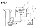
- FIG 4 is a schematic view showing a molding apparatus 101, which is a second embodiment of the molding apparatus in accordance with the present invention.
- the second embodiment of the molding apparatus 101 is constituted basically in the same manner as that in the first embodiment of the molding apparatus 1 of Figure 1 , except that spacing forming means 18 for forming a spacing between the substrate 3 and a mask 102 is provided on the holder 9, and except that the mask 102 is capable of being moved with respect to the substrate 3 (in the direction indicated by the arrow Z in Figure 4 ).
- similar elements are numbered with the same reference numerals with respect to Figure 1 .
- Figures 5A to 5F are explanatory views showing how a molded body is formed in the second embodiment of Figure 4 .
- members other than the mask 102, the substrate 3, and the nozzle 11 are omitted.
- the mask 102 is secured to the spacing forming means 18 (not shown in Figures 5A to 5F ).
- the mask 102 employed in the second embodiment is a comb-shaped mask which does not have the aperture-provided shape.
- the mask shape is not limited to the comb-like shape and may be the aperture-provided shape.
- the aerosol 15 is jetted out from the nozzle 11 via the mask 102 to the substrate 3.
- the mask 102 is moved by the spacing forming means 18 (not shown in Figures 5A to 5F ) in the direction indicated by the arrow Z, and the spacing is formed between the mask 102 and the region of the substrate 3, at which region the mask 102 is located.
- the raw material particles 4 are deposited in the spacing on the substrate 3.
- the movement speed of the mask 102 in the direction indicated by the arrow Z should preferably be equal to approximately 100 ⁇ m/min.
- the effects of the aerosol 15 having been jetted out are the same as those in the first embodiment described above.
- the nozzle 11 is moved by the stage 10 with respect to the substrate 3 in the direction indicated by the arrow Y. In this manner, the raw material particles 4 are deposited in the predetermined region on the substrate 3, and the molded body 17 is formed.
- the mask 102 is then removed from the substrate 3.
- the raw material particles 4 are sintered together, and the mechanical strength of the molded body 17 is enhanced.
- a lattice-shaped polyimide mask having a plurality of aperture regions arrayed in a two-dimensional periodic pattern was prepared. Peripheral regions of the polyimide mask were secured by an adhesive agent to an yttrium stabilized zirconia (YSZ) substrate. Each of the aperture regions had a 220 ⁇ m-square size, and the periodic intervals of the aperture regions were 300 ⁇ m (lattice width: 80 ⁇ m). The thickness of the polyimide mask was 130 ⁇ m.
- PZT lead zirconate titanate particles having a mean particle diameter of 0.3 ⁇ m were mixed with an O 2 gas and were thus aerosolized.
- the obtained aerosol was jetted out from a nozzle via the polyimide mask to the YSZ substrate.
- the nozzle was moved with respect to the YSZ substrate, and the aerosol was jetted to a predetermined area.
- the temperature of the YSZ substrate was the room temperature.
- FIG. 6 is an explanatory view showing a polyimide mask employed in Example 1 in accordance with the present invention and a sectional shape of the mask.
- Figure 7 is an explanatory view showing a PZT molded body having been molded in Example 1 in accordance with the present invention and a sectional shape of the PZT molded body.
- the molded body having thus been obtained was fired at a temperature of 1,100 ° C for three hours in an air atmosphere.
- the PZT sintered body separated from the YSZ substrate.
- the PZT particles which were contained in the aerosol, were deposited in the spacing on the region of the YSZ substrate which region was covered by the polyimide mask. Therefore, in cases where a mask having a complicated shape was used, the PZT particles were deposited on the YSZ substrate in accordance with the mask shape at the region to which the aerosol was jetted out. Also, the PZT particles were deposited principally at the spacing and were adhered to one another. Therefore, the use of an organic binder was suppressed.
Landscapes
- Chemical & Material Sciences (AREA)
- Engineering & Computer Science (AREA)
- Ceramic Engineering (AREA)
- Manufacturing & Machinery (AREA)
- Materials Engineering (AREA)
- Structural Engineering (AREA)
- Organic Chemistry (AREA)
- Inorganic Chemistry (AREA)
- Composite Materials (AREA)
- Other Surface Treatments For Metallic Materials (AREA)
- Devices For Post-Treatments, Processing, Supply, Discharge, And Other Processes (AREA)
- Compositions Of Oxide Ceramics (AREA)
Abstract
Description
- This invention relates to a process and apparatus for producing a ceramic material. This invention particularly relates to a process and apparatus for producing a ceramic material, wherein aerosolized raw material particles are jetted out and wherein the raw material particles are thereby deposited on a substrate to form a molded body.
- Heretofore, injection molding techniques have been utilized as the techniques for producing ceramic materials. With the injection molding techniques, though complicated molded bodies are capable of being molded accurately, mixing proportions of organic binders with respect to molding materials are as high as approximately 50% by weight. Therefore, expansion and contraction differences of the molded bodies at the time of degreasing steps are large. In order for cracking due to the expansion and contraction differences to be prevented, it is necessary to perform the degreasing steps for a long period of time while distributions of temperatures of the molded bodies are being kept to be small at markedly low temperature rising rates.
- For example, in Japanese Unexamined Patent Publication No.
6(1994)-279127 - Also, for example, in Japanese Unexamined Patent Publication No.
2007-162077 - However, with the rapid advances made in development of devices related to micro electro-mechanical systems (MEMS) in recent years, there has arisen a strong demand for formation of fine structures and integration of devices, such as laminated ceramic capacitors and piezoelectric actuators. Also, there is a strong demand for suppression of the use of organic binders such that discharging of the organic binders in the degreasing steps as greenhouse gases may be prevented from the view point of environmental loads, and such that the consumption of energy for long-time heating in the degreasing steps may be prevented.
- With the technique disclosed in Japanese Unexamined Patent Publication No.
6(1994)-279127 - With the technique disclosed in Japanese Unexamined Patent Publication No.
2007-162077 - The primary object of the present invention is to provide a process for producing a ceramic material, wherein molding of a ceramic material having a complicated shape is enabled, and wherein use of an organic binder acting as an environmental load substance is suppressed.
- Another object of the present invention is to provide an apparatus for carrying out the process for producing a ceramic material.
- The present invention provides a first process for producing a ceramic material, comprising the steps of:
- i) locating a mask, which has a predetermined shape, on a substrate,
- ii) forming a spacing between the substrate and the mask, which has the predetermined shape,
- iii) jetting out an aerosol, which contains a carrier gas and raw material particles dispersed in the carrier gas, onto the substrate, and
- iv) causing the jetted-out aerosol to flow into the spacing between the substrate and the mask,
- The term "mask" as used herein broadly means the mask which covers the entire area or a part of the surface of the substrate. The mask is not limited to a single mask and may be constituted of a plurality of masks. Also, the mask is not limited to a specific shape and embraces a mask having an aperture region, a comb-shaped mask, and the like.
- The present invention also provides a second process for producing a ceramic material, comprising the steps of:
- i) covering a substrate by a mask having an aperture region,
- ii) jetting out an aerosol, which contains a carrier gas and raw material particles dispersed in the carrier gas, via the mask toward the substrate, and
- iii) causing the jetted-out aerosol to flow from the aperture region of the mask into a spacing between the mask and a region of the substrate which region is covered by the mask,
- The term "aperture region" as used herein means the aperture region of the mask which has the aperture-provided shape, an edge region of an outer periphery of the comb-shaped mask, or the like.
- Each of the first and second processes for producing a ceramic material in accordance with the present invention may be modified such that the molded body is subjected to firing processing.
- The present invention further provides an apparatus for producing a ceramic material, comprising:
- i) a substrate,
- ii) a mask having an aperture region, which mask is located on the substrate,
- iii) aerosol forming means for forming an aerosol, which contains a carrier gas and raw material particles dispersed in the carrier gas, and
- iv) jetting-out means for jetting out the aerosol via the mask toward the substrate.
- With each of the first and second processes for producing a ceramic material and the apparatus for producing a ceramic material in accordance with the present invention, the jetted-out aerosol is caused to flow into the spacing between the substrate and the mask, and the raw material particles, which are contained in the aerosol, are deposited in the spacing on the region of the substrate, at which region the mask is located. In this manner, the molded body is formed. Therefore, in cases where a mask having a complicated shape, which mask has been formed by etching processing, or the like, is used, the raw material particles are deposited on the substrate in accordance with the mask shape at the region to which the aerosol is jetted out. Accordingly, the molded body having a complicated shape is formed accurately.
- Also, the raw material particles are deposited principally at the spacing and are adhered to one another to form a solid molded body. Therefore, the use of an organic binder acting as an environmental load substance is suppressed. In cases where the molded body is subjected to the firing processing, the raw material particles are sintered together, and therefore a sintered body having an enhanced mechanical strength is obtained.
-
-
Figure 1 is a schematic view showing amolding apparatus 1, which is a first embodiment of the molding apparatus in accordance with the present invention, -
Figure 2 is a perspective view showing amask 2 employed in the first embodiment ofFigure 1 , -
Figures 3A, 3B, 3C, and 3D are explanatory views showing how a molded body is formed in the first embodiment ofFigure 1 , -
Figure 4 is a schematic view showing amolding apparatus 101, which is a second embodiment of the molding apparatus in accordance with the present invention, -
Figures 5A to 5F are explanatory views showing how a molded body is formed in the second embodiment ofFigure 4 , -
Figure 6 is an explanatory view showing a polyimide mask employed in Example in accordance with the present invention and a sectional shape of the mask, and -
Figure 7 is an explanatory view showing a PZT molded body having been molded in Example in accordance with the present invention and a sectional shape of the PZT molded body. - The present invention will hereinbelow be described in further detail with reference to the accompanying drawings.
-
Figure 1 is a schematic view showing amolding apparatus 1, which is a first embodiment of the molding apparatus in accordance with the present invention. - With reference to
Figure 1 , themolding apparatus 1 comprises anaerosolizing chamber 6, in which raw material particles 4 and acarrier gas 5 are mixed together with stirring. Themolding apparatus 1 also comprises amolding chamber 7, in which molding processing is performed. Themolding apparatus 1 further comprises a high-pressure gas cylinder 8 for storing thecarrier gas 5. Themolding chamber 7 is provided with asubstrate 3, on which the raw material particles 4 are to be deposited. Themolding chamber 7 is also provided with aholder 9 for supporting thesubstrate 3. Themolding chamber 7 is further provided with astage 10 for moving theholder 9 in three-dimensional directions (X, Y, Z, and θ directions). Themolding chamber 7 is still further provided with anozzle 11 having a thin orifice, through which the raw material particles 4 are to be jetted out to thesubstrate 3. Themolding apparatus 1 still further comprises afirst pipe line 12 for connecting thenozzle 11 and the aerosolizingchamber 6 to each other. Themolding apparatus 1 also comprises asecond pipe line 13 for connecting the aerosolizingchamber 6 and the high-pressure gas cylinder 8 to each other. Themolding apparatus 1 further comprises avacuum pump 14 for evacuating themolding chamber 7. Themolding apparatus 1 still further comprises amask 2 for covering thesubstrate 3. - In cases where the molding processing is to be performed by use of the
molding apparatus 1, thecarrier gas 5 is introduced from the high-pressure gas cylinder 8, which stores thecarrier gas 5, through thesecond pipe line 13 into the aerosolizingchamber 6, and the raw material particles 4 having been filled in theaerosolizing chamber 6 are vibrated and stirred together with thecarrier gas 5. In theaerosolizing chamber 6, the raw material particles 4 are thus dispersed in thecarrier gas 5, and anaerosol 15 is formed. - The
mask 2 is located on thesubstrate 3. A periphery of themask 2 or a part of themask 2 other than the region of themask 2, which region corresponds to the shape to be molded, is secured to thesubstrate 3. In cases where themask 2 is secured to thesubstrate 3, themask 2 may be secured to thesubstrate 3 by an adhesive agent. Alternatively, themask 2 may be pushed and secured to thesubstrate 3 by use of a fixture. At this time, the securing is performed such that the region of themask 2, which region corresponds to the shape to be molded, is not secured to thesubstrate 3 by the adhesive agent, or the like. - The raw material particles 4 contained in the
aerosol 15 pass through thefirst pipe line 12 and are jetted out from the thin orifice of thenozzle 11, which is located in themolding chamber 7, via themask 2 to thesubstrate 3. When the raw material particles 4 contained in theaerosol 15 pass through thenozzle 11 having the fine orifice of at most 6mm2, the flow rate of the raw material particles 4 is easily increased to a value falling within the range of 2m/sec to 400m/sec. - As a result, the raw material particles 4 are deposited at the spacing between the
substrate 3 and themask 2. The step of jetting out theaerosol 15 via themask 2 to thesubstrate 3 will be described later. - The
molding chamber 7 is evacuated by thevacuum pump 14, and the degree of vacuum in themolding chamber 7 is adjusted when necessary. As described above, theholder 9 for supporting thesubstrate 3 is capable of being moved by thestage 10 in the three-dimensional directions. Therefore, the raw material particles 4 are deposited to a predetermined thickness at the predetermined region of thesubstrate 3. Specifically, in case where the movement speed of thesubstrate 3 relative to thenozzle 11 is controlled by thestage 10, it is possible to control the thickness of the deposited layer of the raw material particles 4 during one time of reciprocating movement of thenozzle 11. - After the raw material particles 4 have been deposited to a predetermined thickness, the
mask 2 is removed from thesubstrate 3. - A molded
body 17 having been formed on thesubstrate 3 as will be described later is put in an electric furnace (not shown). In the electric furnace, the moldedbody 17 is heated at a predetermined temperature rising rate, is kept at a predetermined temperature for a predetermined period of time, and is then cooled. The moldedbody 17 is thus subjected to the firing processing. In cases where the adhesion of the raw material particles 4 to one another is strong or in cases where the raw material particles 4 do not contain an organic binder 16, the firing processing described above need not necessarily be performed. - By the firing processing, the molded
body 17 is sintered, contracted, and separated as the sintered body from thesubstrate 3. The sintered body having been separated from thesubstrate 3 is obtained with the same shape as the shape of the region of themask 2, to which theaerosol 15 has been jetted out from thenozzle 11. -
Figure 2 is a perspective view showing amask 2 employed in the first embodiment ofFigure 1 . As illustrated inFigure 2 , themask 2 comprisesaperture regions region 2b, which is utilized for the securing to thesubstrate 3. In the first embodiment, thesingle mask 2 is employed, and themask 2 has the aperture-provided shape. However, the molding apparatus is not limited to the embodiment described above. For example, as described above, the mask may be constituted of a plurality of masks. Also, the mask shape is not limited to the aperture-provided shape and may be a comb-like shape, or the like. Also, with the first embodiment, the peripheral region of themask 2 is utilized as the securingsection 2b, and therefore dense molding is capable of being performed. Themask 2 may be a metal mask. However, themask 2 should preferably be a polyimide mask. In such cases, denser molded bodies are capable of being molded. Specifically, in the cases of the metal mask, such as a stainless steel mask, the thickness of the mask should preferably be approximately 1mm. In the cases of the polyimide mask, the thickness of the mask should preferably be approximately 130µm. - Reverting to
Figure 1 , in this embodiment, as thesubstrate 3, a zirconia substrate having a high heat resistance is employed. The substrate size may fall within the range of a 5mm-square size to a 50mm-square size and should preferably be a 25mm-square size. At the time of the deposition of the raw material particles 4, the temperature of thesubstrate 3 may be the room temperature and should preferably be adjusted at a predetermined temperature such that denser molded body may be formed. - As the raw material particles 4, particles of lead zirconate titanate (PZT) are employed. The particles should preferably have a mean particle diameter falling within the range of approximately 0.1µm to 3µm. Also, the particles should preferably be such that the proportion of the particles having the particle diameter falling within the range of 0.1µm to 2µm is equal to at least 50% by weight. The term "particle diameter" as used herein means the equivalent sphere diameter, which is the diameter of a sphere having the same volume as the volume of the particle. Also, the term "mean particle diameter" as used herein means the number-average particle diameter. The raw material particles 4 may be granulated particles containing the organic binder 16. Such that the formation of the
aerosol 15 may be enabled, it is necessary for the granulated particles to have a mean particle diameter falling within the range described above. The organic binder 16 may be a polyvinyl alcohol, methyl cellulose, or an acrylic resin. - As the
carrier gas 5, it is possible to use a helium (He) gas, an oxygen (O2) gas, a nitrogen (N2) gas, an argon (Ar) gas, a mixed gas containing two or more of the above-enumerated gases, dry air, or the like. -
Figures 3A, 3B, 3C, and 3D are explanatory views showing how a molded body is formed in the first embodiment ofFigure 1 . InFigures 3A, 3B, 3C, and 3D , for clearness, members other than the cross-sections of themask 2 and thesubstrate 3 are omitted. - As illustrated in
Figure 3A , theaerosol 15 having been jetted out from thenozzle 11 passes through each ofaperture regions mask 2 and impinges upon thesubstrate 3. Theaerosol 15 flows as a turbulent flow within eachaperture region 2a, and the raw material particles 4 are discharged by the turbulent flow from theaperture region 2a. - As illustrated in
Figure 3B , a part of theaerosol 15 flowing as the turbulent flow within theaperture region 2a is discharged from theaperture region 2a, and a part of theaerosol 15 flows into the region between themask 2 and thesubstrate 3. Specifically, themask 2 is bent, and a spacing is formed between themask 2 and thesubstrate 3. - At this stage, as illustrated in
Figure 3C , the raw material particles 4 enter into the spacing, which has been formed between themask 2 and thesubstrate 3 by the flowing of theaerosol 15. Since the raw material particles 4 enter into the spacing, the raw material particles 4 collide with one another and adhere together by the shock. The raw material particles 4 having an increased weight due to the adhesion are pushed in the spacing against thesubstrate 3 and are deposited in the spacing on thesubstrate 3. - As illustrated in
Figure 3D , the jetting out of theaerosol 15 is continued, and theaerosol 15 enters into the spacing even further. As a result, the raw material particles 4 collide with one another and are deposited even further in the spacing on thesubstrate 3. In this manner, the moldedbody 17 is formed. In cases where the moldedbody 17 is subjected to the firing processing in an electric furnace (not shown), the raw material particles 4 are sintered together, and the mechanical strength of the moldedbody 17 is enhanced. - A second embodiment of the molding apparatus in accordance with the present invention will be described hereinbelow.
-
Figure 4 is a schematic view showing amolding apparatus 101, which is a second embodiment of the molding apparatus in accordance with the present invention. The second embodiment of themolding apparatus 101 is constituted basically in the same manner as that in the first embodiment of themolding apparatus 1 ofFigure 1 , except thatspacing forming means 18 for forming a spacing between thesubstrate 3 and amask 102 is provided on theholder 9, and except that themask 102 is capable of being moved with respect to the substrate 3 (in the direction indicated by the arrow Z inFigure 4 ). For facilitating the explanation, inFigure 4 , similar elements are numbered with the same reference numerals with respect toFigure 1 . -
Figures 5A to 5F are explanatory views showing how a molded body is formed in the second embodiment ofFigure 4 . InFigures 5A to 5F , for clearness, members other than themask 102, thesubstrate 3, and thenozzle 11 are omitted. Also, themask 102 is secured to the spacing forming means 18 (not shown inFigures 5A to 5F ). - As illustrated in
Figure 5A , themask 102 employed in the second embodiment is a comb-shaped mask which does not have the aperture-provided shape. However, as in the first embodiment, the mask shape is not limited to the comb-like shape and may be the aperture-provided shape. - As illustrated in
Figure 5B , theaerosol 15 is jetted out from thenozzle 11 via themask 102 to thesubstrate 3. - As illustrated in
Figure 5C , themask 102 is moved by the spacing forming means 18 (not shown inFigures 5A to 5F ) in the direction indicated by the arrow Z, and the spacing is formed between themask 102 and the region of thesubstrate 3, at which region themask 102 is located. The raw material particles 4 are deposited in the spacing on thesubstrate 3. Specifically, the movement speed of themask 102 in the direction indicated by the arrow Z should preferably be equal to approximately 100µm/min. The effects of theaerosol 15 having been jetted out are the same as those in the first embodiment described above. - As illustrated in
Figure 5D , thenozzle 11 is moved by thestage 10 with respect to thesubstrate 3 in the direction indicated by the arrow Y. In this manner, the raw material particles 4 are deposited in the predetermined region on thesubstrate 3, and the moldedbody 17 is formed. - As illustrated in
Figure 5E , at the time at which the thickness of the moldedbody 17 has reached a predetermined value, the jetting out of theaerosol 15 from thenozzle 11 is ceased. - As illustrated in
Figure 5F , themask 102 is then removed from thesubstrate 3. In cases where the moldedbody 17 is subjected to the firing processing in an electric furnace (not shown), the raw material particles 4 are sintered together, and the mechanical strength of the moldedbody 17 is enhanced. - The present invention will further be illustrated by the following non-limitative example.
- A lattice-shaped polyimide mask having a plurality of aperture regions arrayed in a two-dimensional periodic pattern was prepared. Peripheral regions of the polyimide mask were secured by an adhesive agent to an yttrium stabilized zirconia (YSZ) substrate. Each of the aperture regions had a 220µm-square size, and the periodic intervals of the aperture regions were 300µm (lattice width: 80µm). The thickness of the polyimide mask was 130µm.
- Thereafter, PZT (lead zirconate titanate) particles having a mean particle diameter of 0.3µm were mixed with an O2 gas and were thus aerosolized. The obtained aerosol was jetted out from a nozzle via the polyimide mask to the YSZ substrate. The nozzle was moved with respect to the YSZ substrate, and the aerosol was jetted to a predetermined area. The temperature of the YSZ substrate was the room temperature.
- The PZT particles were deposited in the spacing between the polyimide mask and the YSZ substrate, and the height of the polyimide mask rose by 200µm. At this time, the jetting out of the aerosol from the nozzle was ceased, and the polyimide mask was then removed. It was confirmed that a molded body, which had the lattice width of 80µm and had a plurality of 220µm-square aperture regions arrayed at periodical intervals, was formed.
Figure 6 is an explanatory view showing a polyimide mask employed in Example 1 in accordance with the present invention and a sectional shape of the mask.Figure 7 is an explanatory view showing a PZT molded body having been molded in Example 1 in accordance with the present invention and a sectional shape of the PZT molded body. - The molded body having thus been obtained was fired at a temperature of 1,100°C for three hours in an air atmosphere. By the sintering and the contraction due to the firing processing, the PZT sintered body separated from the YSZ substrate.
- Therefore, in cases where the jetted-out aerosol was caused to flow from the aperture region of the polyimide mask into the spacing between the polyimide mask and the region of the YSZ substrate which region was covered by the polyimide mask, the PZT particles, which were contained in the aerosol, were deposited in the spacing on the region of the YSZ substrate which region was covered by the polyimide mask. Therefore, in cases where a mask having a complicated shape was used, the PZT particles were deposited on the YSZ substrate in accordance with the mask shape at the region to which the aerosol was jetted out. Also, the PZT particles were deposited principally at the spacing and were adhered to one another. Therefore, the use of an organic binder was suppressed.
whereby a molded body having the same shape as the shape of the mask is formed.
whereby a molded body is formed.
Claims (4)
- A process for producing a ceramic material, comprising the steps of:i) locating a mask (2, 102), which has a predetermined shape, on a substrate (3),ii) forming a spacing between the substrate (3) and the mask (2, 102), which has the predetermined shape,iii) jetting out an aerosol (15), which contains a carrier gas (5) and raw material particles (4) dispersed in the carrier gas (5), onto the substrate (3), andiv) causing the jetted-out aerosol (15) to flow into the spacing between the substrate (3) and the mask (2, 102),the raw material particles (4), which are contained in the aerosol (15), being deposited in the spacing between the substrate (3) and the mask (2, 102),
whereby a molded body (17) having the same shape as the shape of the mask (2, 102) is formed. - A process for producing a ceramic material, comprising the steps of:i) covering a substrate (3) by a mask (2, 102) having an aperture region (2a, 102a),ii) jetting out an aerosol (15), which contains a carrier gas (5) and raw material particles (4) dispersed in the carrier gas (5), via the mask (2, 102) toward the substrate (3), andiii) causing the jetted-out aerosol (15) to flow from the aperture region (2a, 102a) of the mask (2, 102) into a spacing between the mask (2, 102) and a region of the substrate (3) which region is covered by the mask (2, 102),the raw material particles (4), which are contained in the aerosol (15), being deposited in the spacing on the region of the substrate (3) which region is covered by the mask (2, 102),
whereby a molded body (17) is formed. - A process for producing a ceramic material as defined in Claim 1 or 2 wherein the molded body (17) is subjected to firing processing.
- An apparatus for producing a ceramic material, comprising:i) a substrate (3),ii) a mask (2, 102) having an aperture region (2a, 102a), which mask (2, 102) is located on the substrate (3),iii) aerosol forming means (6) for forming an aerosol (15), which contains a carrier gas (5) and raw material particles (4) dispersed in the carrier gas (5), andiv) jetting-out means (11) for jetting out the aerosol (15) via the mask (2, 102) toward the substrate (3).
Applications Claiming Priority (1)
| Application Number | Priority Date | Filing Date | Title |
|---|---|---|---|
| JP2007281558A JP2009108369A (en) | 2007-10-30 | 2007-10-30 | Ceramic manufacturing method and ceramic manufacturing apparatus |
Publications (2)
| Publication Number | Publication Date |
|---|---|
| EP2055688A2 true EP2055688A2 (en) | 2009-05-06 |
| EP2055688A3 EP2055688A3 (en) | 2012-03-28 |
Family
ID=39967118
Family Applications (1)
| Application Number | Title | Priority Date | Filing Date |
|---|---|---|---|
| EP08018999A Withdrawn EP2055688A3 (en) | 2007-10-30 | 2008-10-30 | Process and apparatus for producing a ceramic material |
Country Status (3)
| Country | Link |
|---|---|
| US (1) | US7914721B2 (en) |
| EP (1) | EP2055688A3 (en) |
| JP (1) | JP2009108369A (en) |
Families Citing this family (1)
| Publication number | Priority date | Publication date | Assignee | Title |
|---|---|---|---|---|
| JP6094344B2 (en) * | 2013-04-10 | 2017-03-15 | 富士通株式会社 | Aerosol deposition apparatus and aerosol deposition method |
Citations (1)
| Publication number | Priority date | Publication date | Assignee | Title |
|---|---|---|---|---|
| JP2007162077A (en) | 2005-12-14 | 2007-06-28 | Fujifilm Corp | Film forming apparatus, film forming method, ceramic film, inorganic structure, and device |
Family Cites Families (7)
| Publication number | Priority date | Publication date | Assignee | Title |
|---|---|---|---|---|
| JP3084286B2 (en) * | 1990-11-22 | 2000-09-04 | 真空冶金株式会社 | Ceramic dielectric thick film capacitor, method of manufacturing the same, and manufacturing apparatus |
| JPH06279127A (en) | 1993-03-30 | 1994-10-04 | Ngk Insulators Ltd | Method and device for dewaxing ceramic injection-molded body |
| JP3015869B2 (en) * | 1997-01-27 | 2000-03-06 | 工業技術院長 | Fine molding method and apparatus |
| JP2006140367A (en) * | 2004-11-15 | 2006-06-01 | Sumitomo Electric Ind Ltd | Heating body for semiconductor manufacturing apparatus and heating apparatus equipped with the same |
| JP2006179856A (en) * | 2004-11-25 | 2006-07-06 | Fuji Electric Holdings Co Ltd | Insulating substrate and semiconductor device |
| JP4793261B2 (en) * | 2005-12-30 | 2011-10-12 | ブラザー工業株式会社 | Thin film forming method and mask used therefor |
| US20070154641A1 (en) * | 2005-12-30 | 2007-07-05 | Brother Kogyo Kabushiki Kaisha | Thin-film forming method and mask used therefor |
-
2007
- 2007-10-30 JP JP2007281558A patent/JP2009108369A/en not_active Withdrawn
-
2008
- 2008-10-30 EP EP08018999A patent/EP2055688A3/en not_active Withdrawn
- 2008-10-30 US US12/261,106 patent/US7914721B2/en not_active Expired - Fee Related
Patent Citations (1)
| Publication number | Priority date | Publication date | Assignee | Title |
|---|---|---|---|---|
| JP2007162077A (en) | 2005-12-14 | 2007-06-28 | Fujifilm Corp | Film forming apparatus, film forming method, ceramic film, inorganic structure, and device |
Also Published As
| Publication number | Publication date |
|---|---|
| US20090110825A1 (en) | 2009-04-30 |
| EP2055688A3 (en) | 2012-03-28 |
| US7914721B2 (en) | 2011-03-29 |
| JP2009108369A (en) | 2009-05-21 |
Similar Documents
| Publication | Publication Date | Title |
|---|---|---|
| US6846558B2 (en) | Colloidal spray method for low cost thin coating deposition | |
| Akedo | Aerosol deposition method for fabrication of nano crystal ceramic layer | |
| EP1597407B1 (en) | Process for the manufacture of a sputtering target | |
| WO2014190211A1 (en) | Aerosol deposition coating for semiconductor chamber components | |
| CN108602726A (en) | The manufacturing method of ceramic sintered bodies and the manufacturing method of ceramic mouldings and manufacturing device | |
| KR20130026478A (en) | Method and arrangement for producing supraconductive layers on substrates | |
| KR20140003336A (en) | Deposition method | |
| Shibuya et al. | Formation of mullite coating by aerosol deposition and microstructural change after heat exposure | |
| EP2113582A2 (en) | Process for forming an improved durability thick ceramic coating | |
| EP2055688A2 (en) | Process and apparatus for producing a ceramic material | |
| JP2006225186A (en) | Firing setter and manufacturing method thereof | |
| KR102928212B1 (en) | Member for semiconductor manufacturing apparatus and semiconductor manufacturing apparatus | |
| US7335341B2 (en) | Method for securing ceramic structures and forming electrical connections on the same | |
| KR100964060B1 (en) | Apparatus and method of depositing powder through transient supply of conveying gas | |
| JP2023513009A (en) | Rapid Induction Sinter Forging for Roll-to-Roll Continuous Manufacturing of Thin Films | |
| CN101177769A (en) | A Plasma Spraying Direct Rapid Manufacturing Method of Porous Materials | |
| Akedo et al. | Fine patterning of ceramic thick layer on aerosol deposition by lift-off process using photoresist | |
| JP6835578B2 (en) | Manufacturing method of ceramic molded product | |
| KR101595541B1 (en) | Setter for making ceramics and method for manufacturing the same | |
| JP5649023B2 (en) | Method for forming zirconia film | |
| CN100554511C (en) | Preparation method with binary metal-base composite material of layered gradient variation | |
| KR101969873B1 (en) | Post-heat treatment method of spinel powder for plasma spray coating on metallic interconnects for solid oxide fuel cells | |
| DE4015208C1 (en) | ||
| KR20180104813A (en) | Method for ceramic coating | |
| US20250092491A1 (en) | Alloy composition for corrosion resistance |
Legal Events
| Date | Code | Title | Description |
|---|---|---|---|
| PUAI | Public reference made under article 153(3) epc to a published international application that has entered the european phase |
Free format text: ORIGINAL CODE: 0009012 |
|
| AK | Designated contracting states |
Kind code of ref document: A2 Designated state(s): AT BE BG CH CY CZ DE DK EE ES FI FR GB GR HR HU IE IS IT LI LT LU LV MC MT NL NO PL PT RO SE SI SK TR |
|
| AX | Request for extension of the european patent |
Extension state: AL BA MK RS |
|
| PUAL | Search report despatched |
Free format text: ORIGINAL CODE: 0009013 |
|
| AK | Designated contracting states |
Kind code of ref document: A3 Designated state(s): AT BE BG CH CY CZ DE DK EE ES FI FR GB GR HR HU IE IS IT LI LT LU LV MC MT NL NO PL PT RO SE SI SK TR |
|
| AX | Request for extension of the european patent |
Extension state: AL BA MK RS |
|
| RIC1 | Information provided on ipc code assigned before grant |
Ipc: C04B 35/491 20060101ALI20120221BHEP Ipc: C04B 35/622 20060101AFI20120221BHEP |
|
| AKY | No designation fees paid | ||
| REG | Reference to a national code |
Ref country code: DE Ref legal event code: R108 |
|
| REG | Reference to a national code |
Ref country code: DE Ref legal event code: R108 Effective date: 20121205 |
|
| STAA | Information on the status of an ep patent application or granted ep patent |
Free format text: STATUS: THE APPLICATION IS DEEMED TO BE WITHDRAWN |
|
| 18D | Application deemed to be withdrawn |
Effective date: 20120929 |