EP2055618A1 - Seat rail of motorcycle - Google Patents
Seat rail of motorcycle Download PDFInfo
- Publication number
- EP2055618A1 EP2055618A1 EP08253366A EP08253366A EP2055618A1 EP 2055618 A1 EP2055618 A1 EP 2055618A1 EP 08253366 A EP08253366 A EP 08253366A EP 08253366 A EP08253366 A EP 08253366A EP 2055618 A1 EP2055618 A1 EP 2055618A1
- Authority
- EP
- European Patent Office
- Prior art keywords
- seat rail
- seat
- concave portion
- motorcycle
- fender
- Prior art date
- Legal status (The legal status is an assumption and is not a legal conclusion. Google has not performed a legal analysis and makes no representation as to the accuracy of the status listed.)
- Granted
Links
Images



Classifications
-
- B—PERFORMING OPERATIONS; TRANSPORTING
- B62—LAND VEHICLES FOR TRAVELLING OTHERWISE THAN ON RAILS
- B62K—CYCLES; CYCLE FRAMES; CYCLE STEERING DEVICES; RIDER-OPERATED TERMINAL CONTROLS SPECIALLY ADAPTED FOR CYCLES; CYCLE AXLE SUSPENSIONS; CYCLE SIDECARS, FORECARS, OR THE LIKE
- B62K11/00—Motorcycles, engine-assisted cycles or motor scooters with one or two wheels
- B62K11/02—Frames
- B62K11/04—Frames characterised by the engine being between front and rear wheels
-
- B—PERFORMING OPERATIONS; TRANSPORTING
- B62—LAND VEHICLES FOR TRAVELLING OTHERWISE THAN ON RAILS
- B62J—CYCLE SADDLES OR SEATS; AUXILIARY DEVICES OR ACCESSORIES SPECIALLY ADAPTED TO CYCLES AND NOT OTHERWISE PROVIDED FOR, e.g. ARTICLE CARRIERS OR CYCLE PROTECTORS
- B62J15/00—Mud-guards for wheels
-
- B—PERFORMING OPERATIONS; TRANSPORTING
- B62—LAND VEHICLES FOR TRAVELLING OTHERWISE THAN ON RAILS
- B62K—CYCLES; CYCLE FRAMES; CYCLE STEERING DEVICES; RIDER-OPERATED TERMINAL CONTROLS SPECIALLY ADAPTED FOR CYCLES; CYCLE AXLE SUSPENSIONS; CYCLE SIDECARS, FORECARS, OR THE LIKE
- B62K19/00—Cycle frames
- B62K19/30—Frame parts shaped to receive other cycle parts or accessories
Definitions
- the present invention relates to the seat rail of a motorcycle.
- a seat rail is provided at the rear of a body of a motorcycle to support a seat, and is usually in the form of right and left members which extend backward from the rear of a main frame forming a front part of the body so as to support the seat (see, for example, JP 1-317886 ).
- JP 1-317886 is concerned with a seat frame of a motorcycle.
- Fig. 1 of JP 1-317886 shows grips 9 which can be held by a passenger of the motorcycle.
- the grips project downward from the sides of the rear of the right and left seat frames, and are U-shaped in section and open upwardly.
- the grips 9 are integrated with rear halves of the left and right seat frames 5, 6, and protrude sideways as shown in Fig. 4 of JP 1-317886 .
- the grips of the seat frames in JP 1-317886 have a number of problems. As they project from both sides of the seat frames, the width of the seat frame is increased. Further, as they are U-shaped and open upwardly, the semi-cylindrical outside faces are gripped when a passenger seated on the rear of the seat grasps the grips, and it can be difficult to grasp these firmly. In addition, when the sides of the grips are covered with a rear fender and a rear cowl to improve the appearance of the motorcycle, the difficulty of grasping the grips is increased.
- the invention is made in view of the above-mentioned problems.
- An object of at least the preferred embodiments of the invention is to provide a seat rail for a motorcycle which can be easily and securely grasped by a passenger, by providing parts which can be grasped by hand on the right and left sides of the seat rail. It is also an object of at least the preferred embodiments of the invention to avoid an increase of vehicle width and to maintain the appearance quality of the vehicle, even when the parts which can be grasped by a hand are provided.
- a seat rail of a motorcycle a front end of which seat rail is supported by an intermediate part of a body frame of the motorcycle and which extends backwards, comprising: a downwardly-open concave portion provided towards the rear of the seat rail, inward from the outside in a direction of vehicle width.
- the concave portion As the concave portion is provided towards the rear of the seat rail, inward and upward from the outside in a direction of vehicle width, fingers may be inserted into the concave portion directed upward when a passenger grasps the concave portion as a part for securing a hand, the inner surface of the concave portion and the outside side in the concave portion of the seat rail hit cushions of the passenger's fingers and the passenger's palm outside the concave portion, and the concave portion can be easily and securely grasped.
- the part for securing a hand does not project outwardly, the size in the direction of width of the right and left seat rails can be reduced, and as the seat rail has no part protruded sideward, the appearance quality of the seat rail may also be improved.
- the seat rail is formed from right and left members, a rear fender is supported by the seat rail, and the rear fender has a convex portion which projects into the concave portion.
- the convex portion of the rear fender is fitted to the concave portion of the seat rail, and as the rear fender is normally made of resin, the part for securing a hand is the concave portion made of resin.
- the concave portion is grasped as the part for securing a hand, a feel of a grasp is satisfactory, and the part can be easy to grasp.
- the concave portion of the seat rail is covered with a rear cowl from the outside in a side view.
- the part for securing a hand formed by the concave portion provided to the rear of the seat rail and the convex portion of the rear fender is concealed from the outside, and as the side of the rear of the rear cowl is exposed in this part, the appearance quality is satisfactory.
- the concave portion of the seat rail is substantially elliptic in a top view; and the convex portion of the rear fender fits within the concave portion.
- the concave portion of the seat rail is substantially elliptic in the top view and the convex portion of the rear fender fits within the concave portion, the whole circumference of the part for securing a hand is surrounded, the whole circumferences of fingers and a palm are surrounded, and the part for securing a hand can be easily and more securely grasped.
- Fig. 1 is a schematic side view showing a motorcycle provided with a seat rail according to a preferred embodiment of the invention.
- a front wheel 3 is steerably supported by a head pipe 2a at a front end of a frame 2 via a front fork 4, a fuel tank 5 is arranged on the upper side of a front half of the frame 2, a rear frame 2c is hung in an intermediate part in a longitudinal direction of the motorcycle, and an engine 6 is arranged between a down tube 2b and the rear frame 2c.
- the engine 6 is a water-cooled in-line four-cylinder engine where plural cylinders 6a are arranged in parallel in a direction of vehicle width.
- Exhaust pipes 7 extend forward, downward and then backward from the fronts of the cylinders 6a of the engine 6, and an exhaust system 8 including a muffler and a silencer is arranged below a crankcase 6b and a transmission case 6c at the back of the crankcase.
- a rear swing arm 9 extends rearward for supporting a rear wheel 10, and is pivotably connected to a lower half of the rear frame 2c.
- a rear cushion unit 11 is inserted between the rear swing arm 9 and the upper side of an intermediate part of the rear frame 2c on the body side.
- reference numeral 12 in Fig. 1 denotes a headlight
- 13 denotes a handlebar
- 14 denotes fuel supply equipment such as a carburettor arranged at the back of the cylinders 6a of the engine
- 15 denotes an air cleaner
- 16 denotes a radiator.
- a seat 20 is arranged behind the fuel tank 5 of the above-mentioned motorcycle, and in the embodiment, the seat 20 is a tandem seat on which the rider and a pillion passenger can be seated in the longitudinal direction.
- the seat 20 is supported by the seat rail 21.
- Fig. 2 is an enlarged side view showing the seat
- Fig. 3 is a sectional view along line 3-3 in Fig. 2
- Fig. 4 is an enlarged side view showing the seat in a state in which a main part shown in Fig. 2 is broken away
- Fig. 5 is a plan showing the seat rail from which the seat is removed
- Fig. 6 is a bottom view showing the seat rail viewed from the bottom.
- the seat rail will now be described with reference to these drawings.
- the seat rail 21 is formed from left and right members 21L, 21R and is formed by a casting, which may be of an aluminium alloy or any suitable material (see Figs. 3 , 5 and 6 ).
- each left and right seat rail member 21 is formed in a V-shape having upper and lower parts 21a, 21b.
- Each seat rail member is provided with mounting parts 21c, 21d at its front end, and is attached to and supported by an upper part and the intermediate part of the rear frame 2c via the front ends (the mounting parts 21c, 21d). Further, each seat rail member extends backward and is inclined upwardly.
- the plan shapes and the bottom shapes of the seat rail members 21L, 21R are shown in Figs. 5 and 6 .
- the rears of the left and right seat rail members 21L, 21R are provided with bottom pieces 21e, and depending parts 21f are integrally formed on the lower and inner parts of bottom pieces 21e, with the inner surfaces of the depending parts 21f being matched and fastened.
- Each seat rail member 21L, 21R is laterally branched in its rear part in the bottom piece 21e in the rear and the hanging part 21f.
- the intermediate rear parts of the seat rails are coupled by an intermediate cross member 31 installed between them, the front parts of the seat rails are coupled by a front cross member 32 installed between them, and the left and right seat rails 21L, 21R are integrated.
- An upwardly concave portion 22 is provided from the outside to the inside (in the direction of vehicle width) in the rear 21g of each left and right seat rail 21L, 21R.
- Both concave portions 22 are provided with standing walls 21h, which project upwardly from the outside of the bottom pieces 21e, and symmetrical U-shaped side frames 21i located above the standing walls, located outside in a lateral direction and open to the outside in the lateral direction as shown in Fig. 3 .
- One concave portion 22 is formed between the right standing wall 21h and the right side frames 21i, and the other concave portion 22 is formed the left standing wall 21h and the left side frame 21i.
- concave portions 22 are holes vertically open in the embodiment as shown in Fig. 3 ; however, they may also be concave portions, grooves or notches respectively provided with ceilings at the crest in place of the holes.
- each concave portion 22 is substantially in the shape of an ellipse surrounded by the side frame 21i in the lateral direction, surrounded by the standing wall 21h inside and surrounded by the frames 21j, 21k in its longitudinal direction.
- a coupling plate 23 couples the frames 21k at the rear.
- a rear fender 40 made of resin is installed between the bottoms of the left and right seat rails 21L, 21R in the embodiment and closes the space between the bottoms of the seat rails 21L, 21R.
- Fig. 5 shows a top face of the rear fender 40 and
- Fig. 6 shows a bottom of the rear fender 40.
- the rear fender 40 is integrated with convex portions 41 which protrude upward at both sides at the rear, and the convex portions 41 fit into the concave portions 22 provided in the rears of the seat rails 21L, 21R.
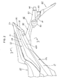
- Fig. 4 clearly shows the protruding shape of the convex portion 41.
- the convex portions are formed in a lateral direction at the rear of the rear fender 40 and are long in the longitudinal direction on their upper sides, with the lateral width smaller than the length and with the convex portions open downwardly and protruded upwards.
- the convex portions 41 of the rear fender 40 are provided at the sides of the rear of the rear fender 40 as described above; further, as shown in Fig. 3 , an opening 40c through which the depending parts 21f at the rear of the seat rails 21L, 21R project downward is provided in a bottom plate 40b of the rear 40a of the rear fender 40.
- the right and left convex portions 41 provided towards the rear of the rear fender 40 are fitted from the lower side into the concave portions 22 provided at the sides of the rears of the seat rails 21L, 21R to close the concave portions 22.
- the top faces 41a of the convex portions 41 close off the upper parts of the concave portions, and downwardly open void spaces 42 which are larger longitudinally than laterally are formed.
- Each downwardly open void space 42 is formed to be slightly longer in its longitudinal direction than the width of a hand, and the lateral width is sufficient to allow insertion of the forefinger to the little finger of a hand in line.
- a rear cowl 50 covers the rear parts of the sides of the above-mentioned left and right seat rails 21L, 21R.
- the rear cowl 50 is made of resin, and is provided with overhanging parts 51 which project laterally symmetrically in a wedge shape, as shown in Fig. 3 .
- each overhanging part 51 covers a substantial part of an outside face, a top face and a bottom of each symmetrical U-shaped side frame 21i which is to the outside at the rear of each seat rail 21L, 21R, and each U-shaped side frame 21i is accommodated in the wedge-shaped space.
- a part 40d below the rear 51a of the overhanging part 51 is a lower part of a side wall of the rear fender 40 shown in Fig. 3 .
- the rear structure including a structure for mounting a fender stay on a rear end 43 of the rear fender 40, will now be described.
- Fig. 8 is a plan view of the rear of the motorcycle including the rear of the seat
- Fig. 9 is a view in the direction shown by arrow 9 in Fig. 8 .
- a front mounting part 44 (shown in the bottom view in Fig. 6 ) is provided toward the rear of the rear fender 40.
- a front half 61 of a fender stay 60 which is narrow width-wise and long in the longitudinal direction as shown in Fig. 7 , is fitted to a fitting part (not shown) formed at the bottom of the rear of the rear fender 40 by inserting a fitting pawl at its end, and the centre of the rear of the front half is connected to the rear of the rear fender 40 by a tapping screw 70.
- a rear half 62 of the fender stay 60 extends from the back of the rear fender 40 and the back of the rear cowl 50 to be the tail 45 of the rear fender 40.
- the rear half 62 of the fender stay 60 is wider than the front half 61, as shown in the bottom view in Fig. 7 , and a license plate 80 holder for mounting a number plate extends backward and downward from the rear half 62.
- the rear half of the lower part of the fender stay 60 is vertically divided into the rear half 62 of the fender stay and the license plate holder 80.
- the rear half 62 of the fender stay and the license plate holder 80 are connected by tapping screws 70 as shown in Fig. 7 .
- Supporting arms 82 extend to the outside in a lateral direction in the vicinity of joining surfaces of a front half 81 of an upper part of the license plate holder 80 and the rear 63 of the fender stay 60 (see Fig. 7 ).
- Right and left rear blinker lamps 83 are attached to and supported by the supporting arms 82.
- a light 84 for illuminating the license plate is housed and installed inside or on a rear face of the rear 63 of the rear fender 60, with a lens surface directed backward, and a reflector 85 is provided at the upper part of the license plate holder 80 immediately under the light 84.
- a concave portion 40m which slightly rearwardly backward in the longitudinal direction, is provided at a rearmost part 40n of the rear fender 40 (see Figs. 5 and 6 ).
- a rear end 51c of the rear cowl 50 extends to the upper edge of the concave portion 40m with the rear end 51c opposite the top of the rearmost part 40n of the rear fender 40, and a void space 52 surrounded by this part is formed (see Fig. 4 ).
- a body including a lamp housing of a tail light 90 is housed in the void space 52, and a lens 92 is exposed to the rear, with the lens pointed backward.
- Lighting equipment such as the tail light 90, the right and left blinker lamps 82, and the light 84 for illuminating the license plate, are wired so that they are connected to a power source and others through the space surrounded by the rear fender 40, the rear cowl 50 and the seat 20 between the left and right seat rails 21L, 21R or one side of the seat rail and the inside on this side of the rear cowl 50.
- a reference numeral 46 shown in Fig. 5 denotes a lid provided to the rear of the rear fender 40, and the lid is provided to conceal the wiring.
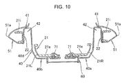
- Fig. 10 is a sectional view showing the rear in Fig. 3 and is a sectional view showing a part including bolts 71 shown in Fig. 5 and similar to Fig. 3 .
- the bolts 71 penetrate the bottom parts 21e of the left and right seat rails 21L, 21R, the bottom plate 40b of the rear 40a of the rear fender 40 which overlap under the bottom parts 21e, and left and right parts of the fender stay 60 which overlap under the bottom plate 40b via each stepped nut from the upside, and these three are fastened by the common bolts 71.
- the three can be connected and integrated by the common bolts, the number of parts can be reduced, and the man-hours required for assembly can also be reduced.
- the seat rails according to the invention are suitable for seat rails that support a tandem seat of a motorcycle.
Landscapes
- Engineering & Computer Science (AREA)
- Mechanical Engineering (AREA)
- Automatic Cycles, And Cycles In General (AREA)
Abstract
The convex portion (22) can be easily and securely grasped, and provides a handgrip without increasing the width of the motorcycle or affecting its appearance quality.
Description
- The present invention relates to the seat rail of a motorcycle.
- A seat rail is provided at the rear of a body of a motorcycle to support a seat, and is usually in the form of right and left members which extend backward from the rear of a main frame forming a front part of the body so as to support the seat (see, for example,
JP 1-317886 -
JP 1-317886 Fig. 1 ofJP 1-317886 grips 9 which can be held by a passenger of the motorcycle. The grips project downward from the sides of the rear of the right and left seat frames, and are U-shaped in section and open upwardly. Thegrips 9 are integrated with rear halves of the left andright seat frames 5, 6, and protrude sideways as shown inFig. 4 ofJP 1-317886 - The grips of the seat frames in
JP 1-317886 - The invention is made in view of the above-mentioned problems.
- An object of at least the preferred embodiments of the invention is to provide a seat rail for a motorcycle which can be easily and securely grasped by a passenger, by providing parts which can be grasped by hand on the right and left sides of the seat rail. It is also an object of at least the preferred embodiments of the invention to avoid an increase of vehicle width and to maintain the appearance quality of the vehicle, even when the parts which can be grasped by a hand are provided.
- According to a first aspect of the present invention, there is provided a seat rail of a motorcycle, a front end of which seat rail is supported by an intermediate part of a body frame of the motorcycle and which extends backwards, comprising: a downwardly-open concave portion provided towards the rear of the seat rail, inward from the outside in a direction of vehicle width.
- As the concave portion is provided towards the rear of the seat rail, inward and upward from the outside in a direction of vehicle width, fingers may be inserted into the concave portion directed upward when a passenger grasps the concave portion as a part for securing a hand, the inner surface of the concave portion and the outside side in the concave portion of the seat rail hit cushions of the passenger's fingers and the passenger's palm outside the concave portion, and the concave portion can be easily and securely grasped.
- Further, the part for securing a hand does not project outwardly, the size in the direction of width of the right and left seat rails can be reduced, and as the seat rail has no part protruded sideward, the appearance quality of the seat rail may also be improved.
- Preferably, the seat rail is formed from right and left members, a rear fender is supported by the seat rail, and the rear fender has a convex portion which projects into the concave portion.
- Accordingly, the convex portion of the rear fender is fitted to the concave portion of the seat rail, and as the rear fender is normally made of resin, the part for securing a hand is the concave portion made of resin. When the concave portion is grasped as the part for securing a hand, a feel of a grasp is satisfactory, and the part can be easy to grasp.
- In a further preferred form, the concave portion of the seat rail is covered with a rear cowl from the outside in a side view.
- As the concave portion of the seat rail is covered with the rear cowl from the outside in the side view, the part for securing a hand formed by the concave portion provided to the rear of the seat rail and the convex portion of the rear fender is concealed from the outside, and as the side of the rear of the rear cowl is exposed in this part, the appearance quality is satisfactory.
- In a further preferred form, the concave portion of the seat rail is substantially elliptic in a top view; and the convex portion of the rear fender fits within the concave portion.
- As the concave portion of the seat rail is substantially elliptic in the top view and the convex portion of the rear fender fits within the concave portion, the whole circumference of the part for securing a hand is surrounded, the whole circumferences of fingers and a palm are surrounded, and the part for securing a hand can be easily and more securely grasped.
- Preferred embodiments of the invention will now be described by way of example only and with reference to the accompanying drawings, in which:
-
Fig. 1 is a schematic side view showing a motorcycle provided with seat rails according to a preferred embodiment of the invention; -
Fig. 2 is an enlarged side view showing a seat; -
Fig. 3 is a sectional view viewed along a line 3-3 inFig. 2 ; -
Fig. 4 is an enlarged side view showing the seat shown in a state in which a main part shown inFig. 2 is broken; -
Fig. 5 is a plan showing the seat rails shown in a state in which the seat is removed; -
Fig. 6 is a bottom view showing the seat rails viewed from their bottoms; -
Fig. 7 is a bottom view showing the rears of the seat rails including a rear fender, a fender stay and a license plate holder; -
Fig. 8 is a plan showing the rear of the motorcycle including the rear of the seat; -
Fig. 9 is a view in the direction shown byarrow 9 inFig. 8 ; and -
Fig. 10 is a sectional view showing a part at the back ofFig. 3 . - Referring to the attached drawings, an embodiment of the invention will be described below. The drawings should be viewed in the direction of reference numerals. In the drawings, Fr denotes the front side of a vehicle, Rr denotes the rear side, R denotes the right based upon the normal position of a rider, and L denotes the left.
-
Fig. 1 is a schematic side view showing a motorcycle provided with a seat rail according to a preferred embodiment of the invention. - In the motorcycle 1, a
front wheel 3 is steerably supported by ahead pipe 2a at a front end of aframe 2 via afront fork 4, afuel tank 5 is arranged on the upper side of a front half of theframe 2, a rear frame 2c is hung in an intermediate part in a longitudinal direction of the motorcycle, and an engine 6 is arranged between adown tube 2b and the rear frame 2c. In the embodiment shown, the engine 6 is a water-cooled in-line four-cylinder engine whereplural cylinders 6a are arranged in parallel in a direction of vehicle width. - Exhaust pipes 7 extend forward, downward and then backward from the fronts of the
cylinders 6a of the engine 6, and anexhaust system 8 including a muffler and a silencer is arranged below acrankcase 6b and a transmission case 6c at the back of the crankcase. - A
rear swing arm 9 extends rearward for supporting arear wheel 10, and is pivotably connected to a lower half of the rear frame 2c. A rear cushion unit 11 is inserted between therear swing arm 9 and the upper side of an intermediate part of the rear frame 2c on the body side. - In addition,
reference numeral 12 inFig. 1 denotes a headlight, 13 denotes a handlebar, 14 denotes fuel supply equipment such as a carburettor arranged at the back of thecylinders 6a of the engine, 15 denotes an air cleaner, and 16 denotes a radiator. - A
seat 20 is arranged behind thefuel tank 5 of the above-mentioned motorcycle, and in the embodiment, theseat 20 is a tandem seat on which the rider and a pillion passenger can be seated in the longitudinal direction. - The
seat 20 is supported by theseat rail 21. -
Fig. 2 is an enlarged side view showing the seat,Fig. 3 is a sectional view along line 3-3 inFig. 2 ,Fig. 4 is an enlarged side view showing the seat in a state in which a main part shown inFig. 2 is broken away,Fig. 5 is a plan showing the seat rail from which the seat is removed, andFig. 6 is a bottom view showing the seat rail viewed from the bottom. The seat rail will now be described with reference to these drawings. - The
seat rail 21 is formed from left andright members Figs. 3 ,5 and6 ). - Referring to
Fig. 1 again, a front end of each left and rightseat rail member 21 is formed in a V-shape having upper andlower parts mounting parts mounting parts - The plan shapes and the bottom shapes of the
seat rail members Figs. 5 and6 . The rears of the left and rightseat rail members bottom pieces 21e, and dependingparts 21f are integrally formed on the lower and inner parts ofbottom pieces 21e, with the inner surfaces of the dependingparts 21f being matched and fastened. - Each
seat rail member bottom piece 21e in the rear and thehanging part 21f. The intermediate rear parts of the seat rails are coupled by anintermediate cross member 31 installed between them, the front parts of the seat rails are coupled by afront cross member 32 installed between them, and the left andright seat rails - An upwardly
concave portion 22 is provided from the outside to the inside (in the direction of vehicle width) in the rear 21g of each left andright seat rail - Both
concave portions 22 are provided with standingwalls 21h, which project upwardly from the outside of thebottom pieces 21e, and symmetrical U-shapedside frames 21i located above the standing walls, located outside in a lateral direction and open to the outside in the lateral direction as shown inFig. 3 . - One
concave portion 22 is formed between the right standingwall 21h and theright side frames 21i, and the otherconcave portion 22 is formed the left standingwall 21h and theleft side frame 21i. - The above-mentioned
concave portions 22 are holes vertically open in the embodiment as shown inFig. 3 ; however, they may also be concave portions, grooves or notches respectively provided with ceilings at the crest in place of the holes. - As clear in the plan view shown in
Fig. 5 ,frames concave portions 22 are provided. In the embodiment, eachconcave portion 22 is substantially in the shape of an ellipse surrounded by theside frame 21i in the lateral direction, surrounded by the standingwall 21h inside and surrounded by theframes - In the embodiment, as shown in
Fig. 5 , acoupling plate 23 couples theframes 21k at the rear. - A
rear fender 40 made of resin is installed between the bottoms of the left andright seat rails seat rails Fig. 5 shows a top face of therear fender 40 andFig. 6 shows a bottom of therear fender 40. - The
rear fender 40 is integrated withconvex portions 41 which protrude upward at both sides at the rear, and theconvex portions 41 fit into theconcave portions 22 provided in the rears of the seat rails 21L, 21R.Fig. 4 clearly shows the protruding shape of theconvex portion 41. The convex portions are formed in a lateral direction at the rear of therear fender 40 and are long in the longitudinal direction on their upper sides, with the lateral width smaller than the length and with the convex portions open downwardly and protruded upwards. - The
convex portions 41 of therear fender 40 are provided at the sides of the rear of therear fender 40 as described above; further, as shown inFig. 3 , anopening 40c through which the dependingparts 21f at the rear of the seat rails 21L, 21R project downward is provided in abottom plate 40b of the rear 40a of therear fender 40. - As shown in
Fig. 3 , the right and leftconvex portions 41 provided towards the rear of therear fender 40 are fitted from the lower side into theconcave portions 22 provided at the sides of the rears of the seat rails 21L, 21R to close theconcave portions 22. The top faces 41a of theconvex portions 41 close off the upper parts of the concave portions, and downwardly openvoid spaces 42 which are larger longitudinally than laterally are formed. - Each downwardly open
void space 42 is formed to be slightly longer in its longitudinal direction than the width of a hand, and the lateral width is sufficient to allow insertion of the forefinger to the little finger of a hand in line. - A
rear cowl 50 covers the rear parts of the sides of the above-mentioned left and right seat rails 21L, 21R. - The
rear cowl 50 is made of resin, and is provided with overhangingparts 51 which project laterally symmetrically in a wedge shape, as shown inFig. 3 . - The
rear part 51a of each overhangingpart 51 covers a substantial part of an outside face, a top face and a bottom of each symmetricalU-shaped side frame 21i which is to the outside at the rear of eachseat rail U-shaped side frame 21i is accommodated in the wedge-shaped space. - Right and left ends 20b of a
bottom plate 20a of theseat 20, which is laid on and supported by the seat rails 21L, 21R, cover and conceal the upwardly-projecting inner ends 51b of the right and left overhangingparts 51 of therear cowl 50. - As shown in
Fig. 2 , apart 40d below the rear 51a of the overhangingpart 51 is a lower part of a side wall of therear fender 40 shown inFig. 3 . - The rear structure, including a structure for mounting a fender stay on a
rear end 43 of therear fender 40, will now be described. -
Fig. 8 is a plan view of the rear of the motorcycle including the rear of the seat, andFig. 9 is a view in the direction shown byarrow 9 inFig. 8 . - A front mounting part 44 (shown in the bottom view in
Fig. 6 ) is provided toward the rear of therear fender 40. Afront half 61 of afender stay 60, which is narrow width-wise and long in the longitudinal direction as shown inFig. 7 , is fitted to a fitting part (not shown) formed at the bottom of the rear of therear fender 40 by inserting a fitting pawl at its end, and the centre of the rear of the front half is connected to the rear of therear fender 40 by a tappingscrew 70. - A
rear half 62 of thefender stay 60 extends from the back of therear fender 40 and the back of therear cowl 50 to be thetail 45 of therear fender 40. - The
rear half 62 of thefender stay 60 is wider than thefront half 61, as shown in the bottom view inFig. 7 , and alicense plate 80 holder for mounting a number plate extends backward and downward from therear half 62. - In the embodiment, the rear half of the lower part of the
fender stay 60 is vertically divided into therear half 62 of the fender stay and thelicense plate holder 80. - The
rear half 62 of the fender stay and thelicense plate holder 80 are connected by tappingscrews 70 as shown inFig. 7 . - Supporting
arms 82 extend to the outside in a lateral direction in the vicinity of joining surfaces of afront half 81 of an upper part of thelicense plate holder 80 and the rear 63 of the fender stay 60 (seeFig. 7 ). Right and leftrear blinker lamps 83 are attached to and supported by the supportingarms 82. - A light 84 for illuminating the license plate is housed and installed inside or on a rear face of the rear 63 of the
rear fender 60, with a lens surface directed backward, and areflector 85 is provided at the upper part of thelicense plate holder 80 immediately under the light 84. - A
concave portion 40m, which slightly rearwardly backward in the longitudinal direction, is provided at arearmost part 40n of the rear fender 40 (seeFigs. 5 and6 ). Arear end 51c of therear cowl 50 extends to the upper edge of theconcave portion 40m with therear end 51c opposite the top of therearmost part 40n of therear fender 40, and avoid space 52 surrounded by this part is formed (seeFig. 4 ). - A body including a lamp housing of a
tail light 90 is housed in thevoid space 52, and alens 92 is exposed to the rear, with the lens pointed backward. - Lighting equipment such as the
tail light 90, the right andleft blinker lamps 82, and the light 84 for illuminating the license plate, are wired so that they are connected to a power source and others through the space surrounded by therear fender 40, therear cowl 50 and theseat 20 between the left and right seat rails 21L, 21R or one side of the seat rail and the inside on this side of therear cowl 50. - A
reference numeral 46 shown inFig. 5 denotes a lid provided to the rear of therear fender 40, and the lid is provided to conceal the wiring. - To explain the common connecting structure of the
seat rail 21, therear fender 40 and thefender stay 60,Fig. 10 is a sectional view showing the rear inFig. 3 and is a sectional view showing apart including bolts 71 shown inFig. 5 and similar toFig. 3 . - The
bolts 71 penetrate thebottom parts 21e of the left and right seat rails 21L, 21R, thebottom plate 40b of the rear 40a of therear fender 40 which overlap under thebottom parts 21e, and left and right parts of the fender stay 60 which overlap under thebottom plate 40b via each stepped nut from the upside, and these three are fastened by thecommon bolts 71. - Thus, the three can be connected and integrated by the common bolts, the number of parts can be reduced, and the man-hours required for assembly can also be reduced.
- The seat rails according to the invention are suitable for seat rails that support a tandem seat of a motorcycle.
Claims (4)
- A seat rail (21) of a motorcycle (1), a front end of which seat rail is supported by an intermediate part of a body frame (2c) of the motorcycle (1) and which extends backwards, comprising:a downwardly-open concave portion (22) provided towards the rear of the seat rail (21), inward from the outside in a direction of vehicle width.
- A seat rail as claimed in claim 1, wherein:the seat rail (21) is formed from right and left members (21L, 21R);a rear fender (40) is supported by the seat rail (21); andthe rear fender (40) has a convex portion (41) which projects into the concave portion (22).
- A seat rail as claimed in claim 2, wherein the concave portion (22) of the seat rail (21) is covered with a rear cowl (50) from the outside in a side view.
- A seat rail as claimed in claim 2, wherein:the concave portion (22) of the seat rail (21) is substantially elliptic in a top view; andthe convex portion (41) of the rear fender (40) fits within the concave portion (22).
Applications Claiming Priority (1)
| Application Number | Priority Date | Filing Date | Title |
|---|---|---|---|
| JP2007286422A JP5033585B2 (en) | 2007-11-02 | 2007-11-02 | Motorcycle seat rail |
Publications (2)
| Publication Number | Publication Date |
|---|---|
| EP2055618A1 true EP2055618A1 (en) | 2009-05-06 |
| EP2055618B1 EP2055618B1 (en) | 2010-12-29 |
Family
ID=40089981
Family Applications (1)
| Application Number | Title | Priority Date | Filing Date |
|---|---|---|---|
| EP08253366A Ceased EP2055618B1 (en) | 2007-11-02 | 2008-10-16 | Motorcycle with a seat rail |
Country Status (5)
| Country | Link |
|---|---|
| US (1) | US8051938B2 (en) |
| EP (1) | EP2055618B1 (en) |
| JP (1) | JP5033585B2 (en) |
| AU (1) | AU2008212090B2 (en) |
| DE (1) | DE602008004203D1 (en) |
Cited By (3)
| Publication number | Priority date | Publication date | Assignee | Title |
|---|---|---|---|---|
| EP2743160A1 (en) * | 2012-12-13 | 2014-06-18 | Honda Motor Co., Ltd. | Rear structure of saddle riding type vehicle |
| CN112533820A (en) * | 2018-08-09 | 2021-03-19 | 本田技研工业株式会社 | Saddle-ride type vehicle |
| US11390343B2 (en) | 2019-02-22 | 2022-07-19 | Suzuki Motor Corporation | Seat rail of motorcycle |
Families Citing this family (12)
| Publication number | Priority date | Publication date | Assignee | Title |
|---|---|---|---|---|
| JP5147498B2 (en) * | 2008-03-31 | 2013-02-20 | 本田技研工業株式会社 | Motorcycle body frame |
| JP5604124B2 (en) * | 2009-03-26 | 2014-10-08 | 本田技研工業株式会社 | Motorcycle |
| JP5423154B2 (en) * | 2009-05-29 | 2014-02-19 | スズキ株式会社 | Motorcycle frame cover mounting structure |
| JP5271224B2 (en) * | 2009-09-25 | 2013-08-21 | 本田技研工業株式会社 | Rear structure of the vehicle |
| US8146524B1 (en) * | 2009-10-30 | 2012-04-03 | Bombardier Recreational Products Inc. | Seating arrangement for a vehicle |
| JP5593123B2 (en) * | 2010-05-28 | 2014-09-17 | 本田技研工業株式会社 | Saddle riding |
| BR112016006358B1 (en) | 2013-09-27 | 2021-06-01 | Honda Motor Co., Ltd. | MOTORCYCLE |
| JP6214706B2 (en) * | 2016-03-30 | 2017-10-18 | 本田技研工業株式会社 | Rear structure of saddle-ride type vehicle |
| JP6302950B2 (en) * | 2016-03-30 | 2018-03-28 | 本田技研工業株式会社 | Rear structure of saddle-ride type vehicle |
| MY189738A (en) * | 2017-09-29 | 2022-02-28 | Honda Motor Co Ltd | Fender structure and saddle riding type vehicle |
| CN112623075B (en) * | 2020-12-23 | 2025-07-22 | 常州豪爵铃木摩托车有限公司 | Motorcycle cushion supporting mechanism and motorcycle |
| JP7340577B2 (en) | 2021-09-30 | 2023-09-07 | 本田技研工業株式会社 | saddle type vehicle |
Citations (5)
| Publication number | Priority date | Publication date | Assignee | Title |
|---|---|---|---|---|
| JPH01317886A (en) | 1988-03-29 | 1989-12-22 | Honda Motor Co Ltd | Seat frame of motorcycle |
| EP1550605A1 (en) | 2002-09-13 | 2005-07-06 | Yamaha Motor Co., Ltd. | Rear frame for two-wheeled motor vehicle and method of casting the same |
| JP2007055283A (en) | 2005-08-22 | 2007-03-08 | Yamaha Motor Co Ltd | Side trunk mounting structure for motorcycles and motorcycles |
| JP2007099084A (en) | 2005-10-04 | 2007-04-19 | Honda Motor Co Ltd | Vehicle frame structure |
| EP1964759A1 (en) * | 2007-02-28 | 2008-09-03 | HONDA MOTOR CO., Ltd. | Seat rail structure of motorcycle |
Family Cites Families (13)
| Publication number | Priority date | Publication date | Assignee | Title |
|---|---|---|---|---|
| JPS6352685U (en) * | 1986-09-26 | 1988-04-08 | ||
| JPS63180392U (en) * | 1987-05-12 | 1988-11-22 | ||
| JP2770168B2 (en) * | 1987-10-12 | 1998-06-25 | ヤマハ発動機株式会社 | Rear structure of motorcycle body |
| JPH01247288A (en) * | 1988-03-29 | 1989-10-03 | Honda Motor Co Ltd | Frame of motorcycle |
| JP3104793B2 (en) * | 1989-02-09 | 2000-10-30 | 株式会社アマダ | Cutting equipment |
| JP2777617B2 (en) * | 1989-09-16 | 1998-07-23 | 本田技研工業株式会社 | Motorcycle frame |
| JPH03266785A (en) * | 1990-05-31 | 1991-11-27 | Honda Motor Co Ltd | motorcycle |
| DE4330120C2 (en) * | 1993-09-06 | 1998-03-19 | Bayerische Motoren Werke Ag | Split seat for one vehicle |
| JP3266785B2 (en) * | 1996-02-15 | 2002-03-18 | 株式会社クラレ | UV reflective white fabric |
| JP4056615B2 (en) * | 1998-03-27 | 2008-03-05 | 本田技研工業株式会社 | Body cover mounting structure |
| DE602004013153T2 (en) * | 2003-07-01 | 2009-05-14 | Yamaha Hatsudoki K.K., Iwata | MOTORCYCLE |
| JP2006088892A (en) * | 2004-09-24 | 2006-04-06 | Yamaha Motor Co Ltd | Saddle riding vehicle |
| US7883136B2 (en) * | 2007-01-17 | 2011-02-08 | Polaris Industries Inc. | Two-wheeled vehicle |
-
2007
- 2007-11-02 JP JP2007286422A patent/JP5033585B2/en not_active Expired - Fee Related
-
2008
- 2008-09-09 AU AU2008212090A patent/AU2008212090B2/en not_active Ceased
- 2008-10-14 US US12/287,879 patent/US8051938B2/en not_active Expired - Fee Related
- 2008-10-16 EP EP08253366A patent/EP2055618B1/en not_active Ceased
- 2008-10-16 DE DE602008004203T patent/DE602008004203D1/en active Active
Patent Citations (5)
| Publication number | Priority date | Publication date | Assignee | Title |
|---|---|---|---|---|
| JPH01317886A (en) | 1988-03-29 | 1989-12-22 | Honda Motor Co Ltd | Seat frame of motorcycle |
| EP1550605A1 (en) | 2002-09-13 | 2005-07-06 | Yamaha Motor Co., Ltd. | Rear frame for two-wheeled motor vehicle and method of casting the same |
| JP2007055283A (en) | 2005-08-22 | 2007-03-08 | Yamaha Motor Co Ltd | Side trunk mounting structure for motorcycles and motorcycles |
| JP2007099084A (en) | 2005-10-04 | 2007-04-19 | Honda Motor Co Ltd | Vehicle frame structure |
| EP1964759A1 (en) * | 2007-02-28 | 2008-09-03 | HONDA MOTOR CO., Ltd. | Seat rail structure of motorcycle |
Cited By (4)
| Publication number | Priority date | Publication date | Assignee | Title |
|---|---|---|---|---|
| EP2743160A1 (en) * | 2012-12-13 | 2014-06-18 | Honda Motor Co., Ltd. | Rear structure of saddle riding type vehicle |
| CN112533820A (en) * | 2018-08-09 | 2021-03-19 | 本田技研工业株式会社 | Saddle-ride type vehicle |
| CN112533820B (en) * | 2018-08-09 | 2022-04-26 | 本田技研工业株式会社 | saddle-ridden vehicle |
| US11390343B2 (en) | 2019-02-22 | 2022-07-19 | Suzuki Motor Corporation | Seat rail of motorcycle |
Also Published As
| Publication number | Publication date |
|---|---|
| EP2055618B1 (en) | 2010-12-29 |
| JP2009113557A (en) | 2009-05-28 |
| DE602008004203D1 (en) | 2011-02-10 |
| US20090114466A1 (en) | 2009-05-07 |
| JP5033585B2 (en) | 2012-09-26 |
| US8051938B2 (en) | 2011-11-08 |
| AU2008212090A1 (en) | 2009-05-21 |
| AU2008212090B2 (en) | 2010-12-16 |
Similar Documents
| Publication | Publication Date | Title |
|---|---|---|
| EP2055618B1 (en) | Motorcycle with a seat rail | |
| EP2011726B1 (en) | Rear fender for a motorcycle | |
| EP1285847B1 (en) | Tail lamp structure for motorcycle | |
| EP1245442B1 (en) | Vehicle rear structure | |
| CN101249857A (en) | Motorcycle front body cover structure | |
| AU2012200297B2 (en) | Headlamp Device | |
| JPWO2011104748A1 (en) | Rear structure of motorcycle | |
| JP5546897B2 (en) | Intake air temperature sensor arrangement structure for motorcycles | |
| JP5292607B2 (en) | Rear lighting system for vehicles | |
| JP2009234424A (en) | Harness retaining structure for saddle riding type vehicle | |
| EP2343233B1 (en) | saddle-riding type vehicle with front lighting apparatus structure | |
| CN102530138A (en) | Light apparatus for motorbike | |
| CN104512498B (en) | The tail lamp structure of vehicle | |
| EP2077221A2 (en) | Straddle-type vehicle | |
| US7325952B2 (en) | Lamp and motorcycle provided with the lamp | |
| EP2557025A1 (en) | Back part structure of body in saddle-ride type vehicle | |
| JP5806483B2 (en) | Vehicle with cowl | |
| CN203511942U (en) | Straddle vehicle | |
| BRPI1104638A2 (en) | motorcycle rear frame | |
| CN101531225B (en) | Rear side cover support structure of motorcycle | |
| US20030067781A1 (en) | Vehicular light-emitting device | |
| JP6935978B2 (en) | Saddle-type vehicle | |
| TWI254010B (en) | Lighting apparatus support device of motorcycle | |
| KR100953603B1 (en) | Leg shield structure of motorcycle | |
| CA2752077A1 (en) | Wiring structure of rear combination light |
Legal Events
| Date | Code | Title | Description |
|---|---|---|---|
| PUAI | Public reference made under article 153(3) epc to a published international application that has entered the european phase |
Free format text: ORIGINAL CODE: 0009012 |
|
| AK | Designated contracting states |
Kind code of ref document: A1 Designated state(s): AT BE BG CH CY CZ DE DK EE ES FI FR GB GR HR HU IE IS IT LI LT LU LV MC MT NL NO PL PT RO SE SI SK TR |
|
| AX | Request for extension of the european patent |
Extension state: AL BA MK RS |
|
| 17P | Request for examination filed |
Effective date: 20090422 |
|
| 17Q | First examination report despatched |
Effective date: 20091214 |
|
| AKX | Designation fees paid |
Designated state(s): DE FR GB IT |
|
| GRAP | Despatch of communication of intention to grant a patent |
Free format text: ORIGINAL CODE: EPIDOSNIGR1 |
|
| RTI1 | Title (correction) |
Free format text: MOTORCYCLE WITH A SEAT RAIL |
|
| RIN1 | Information on inventor provided before grant (corrected) |
Inventor name: TSUTSUI, NORIYOSHIC/O HONDA R&D CO., LTD. Inventor name: NISHIJIMA, TOMOKIC/O HONDA R&D CO., LTD. |
|
| GRAS | Grant fee paid |
Free format text: ORIGINAL CODE: EPIDOSNIGR3 |
|
| GRAA | (expected) grant |
Free format text: ORIGINAL CODE: 0009210 |
|
| AK | Designated contracting states |
Kind code of ref document: B1 Designated state(s): DE FR GB IT |
|
| REG | Reference to a national code |
Ref country code: GB Ref legal event code: FG4D |
|
| REF | Corresponds to: |
Ref document number: 602008004203 Country of ref document: DE Date of ref document: 20110210 Kind code of ref document: P |
|
| REG | Reference to a national code |
Ref country code: DE Ref legal event code: R096 Ref document number: 602008004203 Country of ref document: DE Effective date: 20110210 |
|
| PLBE | No opposition filed within time limit |
Free format text: ORIGINAL CODE: 0009261 |
|
| STAA | Information on the status of an ep patent application or granted ep patent |
Free format text: STATUS: NO OPPOSITION FILED WITHIN TIME LIMIT |
|
| 26N | No opposition filed |
Effective date: 20110930 |
|
| REG | Reference to a national code |
Ref country code: DE Ref legal event code: R097 Ref document number: 602008004203 Country of ref document: DE Effective date: 20110930 |
|
| REG | Reference to a national code |
Ref country code: FR Ref legal event code: PLFP Year of fee payment: 9 |
|
| REG | Reference to a national code |
Ref country code: FR Ref legal event code: PLFP Year of fee payment: 10 |
|
| REG | Reference to a national code |
Ref country code: FR Ref legal event code: PLFP Year of fee payment: 11 |
|
| PGFP | Annual fee paid to national office [announced via postgrant information from national office to epo] |
Ref country code: FR Payment date: 20180913 Year of fee payment: 11 |
|
| PGFP | Annual fee paid to national office [announced via postgrant information from national office to epo] |
Ref country code: IT Payment date: 20181018 Year of fee payment: 11 Ref country code: GB Payment date: 20181010 Year of fee payment: 11 |
|
| REG | Reference to a national code |
Ref country code: DE Ref legal event code: R084 Ref document number: 602008004203 Country of ref document: DE |
|
| GBPC | Gb: european patent ceased through non-payment of renewal fee |
Effective date: 20191016 |
|
| PG25 | Lapsed in a contracting state [announced via postgrant information from national office to epo] |
Ref country code: FR Free format text: LAPSE BECAUSE OF NON-PAYMENT OF DUE FEES Effective date: 20191031 Ref country code: IT Free format text: LAPSE BECAUSE OF NON-PAYMENT OF DUE FEES Effective date: 20191016 Ref country code: GB Free format text: LAPSE BECAUSE OF NON-PAYMENT OF DUE FEES Effective date: 20191016 |
|
| PGFP | Annual fee paid to national office [announced via postgrant information from national office to epo] |
Ref country code: DE Payment date: 20220831 Year of fee payment: 15 |
|
| REG | Reference to a national code |
Ref country code: DE Ref legal event code: R119 Ref document number: 602008004203 Country of ref document: DE |
|
| PG25 | Lapsed in a contracting state [announced via postgrant information from national office to epo] |
Ref country code: DE Free format text: LAPSE BECAUSE OF NON-PAYMENT OF DUE FEES Effective date: 20240501 |