EP2054992B1 - Rotor für einen elektromotor - Google Patents
Rotor für einen elektromotor Download PDFInfo
- Publication number
- EP2054992B1 EP2054992B1 EP07787944A EP07787944A EP2054992B1 EP 2054992 B1 EP2054992 B1 EP 2054992B1 EP 07787944 A EP07787944 A EP 07787944A EP 07787944 A EP07787944 A EP 07787944A EP 2054992 B1 EP2054992 B1 EP 2054992B1
- Authority
- EP
- European Patent Office
- Prior art keywords
- rotor
- rotor core
- shaped articles
- adhesive
- laminated
- Prior art date
- Legal status (The legal status is an assumption and is not a legal conclusion. Google has not performed a legal analysis and makes no representation as to the accuracy of the status listed.)
- Not-in-force
Links
- 239000000853 adhesive Substances 0.000 claims description 24
- 230000001070 adhesive effect Effects 0.000 claims description 24
- 238000003475 lamination Methods 0.000 claims description 6
- 239000012811 non-conductive material Substances 0.000 claims description 3
- 125000006850 spacer group Chemical group 0.000 claims description 3
- 239000011521 glass Substances 0.000 claims description 2
- 229920003023 plastic Polymers 0.000 claims description 2
- 239000004033 plastic Substances 0.000 claims description 2
- 239000011324 bead Substances 0.000 description 7
- 238000000034 method Methods 0.000 description 4
- 238000000465 moulding Methods 0.000 description 3
- 238000004026 adhesive bonding Methods 0.000 description 1
- 230000001419 dependent effect Effects 0.000 description 1
- 238000011161 development Methods 0.000 description 1
- 230000018109 developmental process Effects 0.000 description 1
- 239000002184 metal Substances 0.000 description 1
- 239000012778 molding material Substances 0.000 description 1
- 230000007935 neutral effect Effects 0.000 description 1
- 238000003825 pressing Methods 0.000 description 1
- 238000004080 punching Methods 0.000 description 1
Images

Classifications
-
- H—ELECTRICITY
- H02—GENERATION; CONVERSION OR DISTRIBUTION OF ELECTRIC POWER
- H02K—DYNAMO-ELECTRIC MACHINES
- H02K1/00—Details of the magnetic circuit
- H02K1/06—Details of the magnetic circuit characterised by the shape, form or construction
- H02K1/22—Rotating parts of the magnetic circuit
- H02K1/28—Means for mounting or fastening rotating magnetic parts on to, or to, the rotor structures
-
- H—ELECTRICITY
- H02—GENERATION; CONVERSION OR DISTRIBUTION OF ELECTRIC POWER
- H02K—DYNAMO-ELECTRIC MACHINES
- H02K1/00—Details of the magnetic circuit
- H02K1/06—Details of the magnetic circuit characterised by the shape, form or construction
- H02K1/22—Rotating parts of the magnetic circuit
- H02K1/28—Means for mounting or fastening rotating magnetic parts on to, or to, the rotor structures
- H02K1/30—Means for mounting or fastening rotating magnetic parts on to, or to, the rotor structures using intermediate parts, e.g. spiders
-
- H—ELECTRICITY
- H02—GENERATION; CONVERSION OR DISTRIBUTION OF ELECTRIC POWER
- H02K—DYNAMO-ELECTRIC MACHINES
- H02K1/00—Details of the magnetic circuit
- H02K1/06—Details of the magnetic circuit characterised by the shape, form or construction
- H02K1/22—Rotating parts of the magnetic circuit
- H02K1/27—Rotor cores with permanent magnets
- H02K1/2706—Inner rotors
- H02K1/272—Inner rotors the magnetisation axis of the magnets being perpendicular to the rotor axis
- H02K1/274—Inner rotors the magnetisation axis of the magnets being perpendicular to the rotor axis the rotor consisting of two or more circumferentially positioned magnets
- H02K1/2753—Inner rotors the magnetisation axis of the magnets being perpendicular to the rotor axis the rotor consisting of two or more circumferentially positioned magnets the rotor consisting of magnets or groups of magnets arranged with alternating polarity
- H02K1/278—Surface mounted magnets; Inset magnets
-
- H—ELECTRICITY
- H02—GENERATION; CONVERSION OR DISTRIBUTION OF ELECTRIC POWER
- H02K—DYNAMO-ELECTRIC MACHINES
- H02K15/00—Processes or apparatus specially adapted for manufacturing, assembling, maintaining or repairing of dynamo-electric machines
- H02K15/02—Processes or apparatus specially adapted for manufacturing, assembling, maintaining or repairing of dynamo-electric machines of stator or rotor bodies
- H02K15/03—Processes or apparatus specially adapted for manufacturing, assembling, maintaining or repairing of dynamo-electric machines of stator or rotor bodies having permanent magnets
-
- Y—GENERAL TAGGING OF NEW TECHNOLOGICAL DEVELOPMENTS; GENERAL TAGGING OF CROSS-SECTIONAL TECHNOLOGIES SPANNING OVER SEVERAL SECTIONS OF THE IPC; TECHNICAL SUBJECTS COVERED BY FORMER USPC CROSS-REFERENCE ART COLLECTIONS [XRACs] AND DIGESTS
- Y10—TECHNICAL SUBJECTS COVERED BY FORMER USPC
- Y10T—TECHNICAL SUBJECTS COVERED BY FORMER US CLASSIFICATION
- Y10T29/00—Metal working
- Y10T29/49—Method of mechanical manufacture
- Y10T29/49002—Electrical device making
- Y10T29/49009—Dynamoelectric machine
- Y10T29/49012—Rotor
Definitions
- the invention relates to a rotor for an electric motor, which has a rotor shaft, a laminated rotor core on the rotor core, an annular body surrounding the rotor core and a space provided between the rotor core and the annular body gap, in which is introduced for fixing the ring body on the rotor laminated core adhesive.
- Brushless DC motors are already known in which permanent magnets are located on the rotor surface. These permanent magnets are usually realized as ring magnets. In the arrangement of such permanent magnets on the rotor surface, a return body is provided between the rotor shaft and the permanent magnets, which is fixedly connected to the rotor shaft. The annular realized permanent magnets are glued to this return body, so that a torque can be transmitted via the return body to the rotor shaft.
- the width of the adhesive gap between the ring magnet and the return wrench body must comply with an upper and a lower limit in order to achieve optimum bonding. This bonding should be done so that the ring magnet sits centrally to prevent imbalance. For this purpose, usually a complicated adhesive device is provided, which is to be equipped with the components to be bonded.
- a rotor for a brushless DC motor and a method of assembling such a rotor are known.
- This known rotor has a shaft, a yoke body arranged on the shaft and a ring magnet surrounding the yoke body.
- a gap is formed in the axially extending region between the return body and the ring magnet.
- a holding element is provided, which outside the gap on the one hand with the shaft or the return body and on the other hand with the Ring magnet is connected.
- this holding element of the ring magnet is non-positively connected to the shaft or the yoke body and also centered with respect to the shaft or the yoke body.
- a jacket is preferably provided which surrounds the ring magnet.
- the holding element and the jacket are integrally formed as a sleeve, wherein the ring magnet is connected by pressing into the sleeve with this non-positively.
- a central arrangement of the ring magnet relative to the rotor shaft or the return body is achieved without the need for bonding.
- the object of the invention is to develop a rotor having the features specified in the preamble of claim 1 in such a way that the coaxiality of the annular body is ensured in a simplified manner.
- the adhesive which is introduced into the gap provided between the rotor laminated core and the annular body is admixed with moldings serving as spacers.
- this molding material added to the adhesive it is ensured that an adhesive gap of uniform dimensions is present in the region of the entire lateral surface of the rotor laminated core.
- Said shaped bodies which are preferably spherical, ensure centering of the annular body with respect to the rotor shaft. They consist of a dimensionally stable, electrically non-conductive material, so that the electrical properties of the rotor and thus of the entire electric motor are not influenced in an undesirable manner.
- the lateral surface of the rotor laminated core is provided with elevations and depressions. This is easier
- the rotor core is composed of a plurality of individual sheets, which are each twisted by 60 ° axially associated with a neighboring plate and are each provided on their lateral surface in the circumferential direction at intervals of 60 ° alternately with elevations and depressions.
- Such individual sheets can be produced in a simple manner by means of a stamping process.
- beads of different diameters are added to the adhesive. These diameters are chosen such that a maximum and a minimum adhesive gap can be maintained. Beads whose diameters are too large for the adhesive gap present in each case are deposited in the depressions of the lateral surface of the rotor laminated core, while the other beads ensure the desired centering or coaxiality of the annular body.
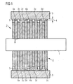
- FIG. 1 shows a schematic longitudinal sectional view of a rotor according to the invention.
- This rotor has a rotor shaft 1, on which a rotor core 2 is fixed. This is composed of a plurality of individual sheets 2a.
- the lateral surface of the rotor laminated core has elevations 2c and depressions 2d.
- the rotor core is surrounded by an annular body 3. There is a gap 4 between the rotor laminated core 2 and the annular body 3. Adhesive 5 is introduced into this gap 4 in order to fix the annular body 3 to the rotor laminated core.
- the molded body 6a, 6b are added to the adhesive, which serve as spacers. Through these moldings it is ensured that there is always a desired minimum distance between the rotor laminated core 2 and annular body 3. Furthermore, the desired centricity or coaxiality of the annular body to the rotor shaft is ensured by these moldings.
- the adhesive 5, to which the beads 6a and 6b are added is first applied to the outer surface of the rotor core in a first step. Then, in a second step, the ring body 3 is slid open in the axial direction, if necessary while rotating, onto the rotor laminated core provided with adhesive. In this sliding, the beads 6b, the diameter of which are too large for the present adhesive gap 4, pressed into the recesses 2d of the lateral surface of the rotor laminated core, as shown in the FIG. 1 is illustrated.
- the beads 6a with the smaller diameter remain in this pushing in a sufficient number between the elevations 2c of the lateral surface and the annular body, whereby the desired distance between the annular body and the rotor core set and the desired centricity or coaxiality of the annular body is ensured relative to the rotor shaft.
- the shaped bodies 6a and 6b are preferably small spheres of a dimensionally stable, electrically non-conductive material, for example glass or plastic. This ensures that the electrical properties of the rotor and thus of the entire electric motor are not influenced in an undesired manner.
- a rotor core 2, as in the FIG. 1 can be produced in a simple manner cost neutral compared to previously used rotor laminations. It consists, as from the perspective view according to the FIG. 2 stating from a plurality of individual sheets 2a, which are each formed by means of a punching process.
- the lateral surface 2b of the rotor core 2 has alternately elevations and depressions both in the axial direction 7 and in the circumferential direction 8.
- each single sheet is provided with six linking points, by means of which the single sheet is connectable to a neighboring sheet metal.
- Each single sheet has on its lateral surface in the circumferential direction at intervals of 60 ° alternately elevations and depressions.
- Adjacent individual sheets are each mutually rotated by 60 ° attached to each other. This has the consequence that the outer surface of the rotor core, as shown in FIG. 2 can be seen, both in the axial direction 7 and in the circumferential direction 8 alternately has the desired elevations and depressions, which correspond to a corrugation of the lateral surface of the rotor core.
- a rotationally symmetrical adhesive gap is provided, which ensures a coaxial bonding of the annular body 3 on the lateral surface of the rotor laminated core 2.
- the strength of the bond is improved by the described corrugation of the lateral surface of the rotor core. Run-out deviations of the rotor are reduced.
- the corrugation of the lateral surface of the rotor laminated core allows centering in the entire adhesive gap tolerance field characterized in that the beads, which are too large for the self-adjusting adhesive gap, deposit in the recesses of the lateral surface. Furthermore, it is achieved that always stores a defined amount of adhesive in the wells or in the corrugation. This will cause the entire Adhesive surface is wetted with adhesive, which improves the overall gluing process.
Landscapes
- Engineering & Computer Science (AREA)
- Power Engineering (AREA)
- Manufacturing & Machinery (AREA)
- Iron Core Of Rotating Electric Machines (AREA)
- Permanent Field Magnets Of Synchronous Machinery (AREA)
Priority Applications (1)
| Application Number | Priority Date | Filing Date | Title |
|---|---|---|---|
| PL07787944T PL2054992T3 (pl) | 2006-08-14 | 2007-07-26 | Wirnik do silnika elektrycznego |
Applications Claiming Priority (2)
| Application Number | Priority Date | Filing Date | Title |
|---|---|---|---|
| DE102006038017 | 2006-08-14 | ||
| PCT/EP2007/057724 WO2008019932A1 (de) | 2006-08-14 | 2007-07-26 | Rotor für einen elektromotor |
Publications (2)
| Publication Number | Publication Date |
|---|---|
| EP2054992A1 EP2054992A1 (de) | 2009-05-06 |
| EP2054992B1 true EP2054992B1 (de) | 2012-12-12 |
Family
ID=38776237
Family Applications (1)
| Application Number | Title | Priority Date | Filing Date |
|---|---|---|---|
| EP07787944A Not-in-force EP2054992B1 (de) | 2006-08-14 | 2007-07-26 | Rotor für einen elektromotor |
Country Status (6)
| Country | Link |
|---|---|
| US (1) | US8040015B2 (pl) |
| EP (1) | EP2054992B1 (pl) |
| KR (1) | KR101323522B1 (pl) |
| CN (1) | CN101553971B (pl) |
| PL (1) | PL2054992T3 (pl) |
| WO (1) | WO2008019932A1 (pl) |
Families Citing this family (20)
| Publication number | Priority date | Publication date | Assignee | Title |
|---|---|---|---|---|
| DE102010031399A1 (de) * | 2010-07-15 | 2012-01-19 | Hilti Aktiengesellschaft | Rotor für einen Elektromotor, Elektromotor und Herstellungsverfahren für einen Elektromotor |
| JP5634383B2 (ja) * | 2011-11-18 | 2014-12-03 | 三菱電機株式会社 | 回転電機用ロータおよび電動パワーステアリング用モータ |
| KR20140028737A (ko) * | 2012-08-30 | 2014-03-10 | 현대모비스 주식회사 | 고출력 모터용 회전자 |
| US20140239764A1 (en) | 2013-02-27 | 2014-08-28 | Regal Beloit America, Inc. | Laminated rotor with improved magnet adhesion and method of fabricating |
| DE102015000769A1 (de) * | 2015-01-26 | 2016-07-28 | Brose Fahrzeugteile GmbH & Co. Kommanditgesellschaft, Würzburg | Stator für einen Elektromotor sowie Verfahren zu dessen Herstellung |
| JP6308177B2 (ja) * | 2015-06-26 | 2018-04-11 | 株式会社デンソー | 回転子 |
| JP6498315B2 (ja) * | 2015-11-26 | 2019-04-10 | 三菱電機株式会社 | 回転子、モータ、空気調和装置および回転子の製造方法 |
| CN107872108A (zh) * | 2016-09-23 | 2018-04-03 | 博世汽车部件(长沙)有限公司 | 电机及其转子 |
| US11264850B2 (en) * | 2019-09-05 | 2022-03-01 | Nidec Motor Corporation | Laminated rotor having deflecting magnet retaining prongs and support posts for the prongs |
| DE102019218437A1 (de) | 2019-11-28 | 2021-06-02 | Robert Bosch Gmbh | Rotor für eine Elektromaschine und Verfahren zur Herstellung eines Rotors |
| US11509193B2 (en) | 2019-12-19 | 2022-11-22 | Black & Decker Inc. | Power tool with compact motor assembly |
| US11705778B2 (en) | 2019-12-19 | 2023-07-18 | Black & Decker Inc. | Power tool with compact motor assembly |
| US12059775B2 (en) | 2019-12-19 | 2024-08-13 | Black & Decker Inc. | Power tool with compact motor assembly |
| EP3890163A1 (fr) * | 2020-04-01 | 2021-10-06 | GE Energy Power Conversion Technology Ltd. | Procede de dimensionnement d'un rotor a arbre non traversant, rotor et motocompresseur associes |
| KR102471079B1 (ko) * | 2020-12-01 | 2022-11-25 | 주식회사 에스 씨디 | 모터용 로터 |
| US11916447B2 (en) * | 2021-06-07 | 2024-02-27 | Black & Decker Inc. | Overmolded rotor structure |
| US12068639B2 (en) | 2021-06-07 | 2024-08-20 | Black & Decker Inc. | Motor rotor with sleeve for retention of magnet ring |
| CN113890287A (zh) * | 2021-09-30 | 2022-01-04 | 南京智慧阳光科技有限公司 | 电机转子叠片叠压设备及叠压方法 |
| DE102022203531A1 (de) * | 2022-04-07 | 2023-10-12 | Robert Bosch Gesellschaft mit beschränkter Haftung | Rotor einer elektrischen Maschine |
| WO2025201720A1 (de) | 2024-03-25 | 2025-10-02 | Sew-Eurodrive Gmbh & Co Kg | Elektromotor, aufweisend einen drehbar gelagerten rotor |
Family Cites Families (17)
| Publication number | Priority date | Publication date | Assignee | Title |
|---|---|---|---|---|
| US3655482A (en) * | 1969-12-23 | 1972-04-11 | Edo Corp | Bonding method and product |
| KR930008984B1 (ko) * | 1991-07-23 | 1993-09-17 | 삼성전기 주식회사 | 모터 회전자의 영구자석 설치구 |
| US5232962A (en) * | 1991-10-09 | 1993-08-03 | Quantum Materials, Inc. | Adhesive bonding composition with bond line limiting spacer system |
| JP3398977B2 (ja) * | 1992-07-14 | 2003-04-21 | 株式会社安川電機 | 永久磁石界磁ロータ |
| GB2271219A (en) | 1992-09-22 | 1994-04-06 | Simmonds Precision Engine Syst | Preventing interlayer shorting in a magnetic alloy laminate |
| US5801470A (en) * | 1996-12-19 | 1998-09-01 | General Electric Company | Rotors with retaining cylinders and reduced harmonic field effect losses |
| US5898990A (en) * | 1997-04-14 | 1999-05-04 | General Motors Corporation | Method of assembling a magnet ring on a rotor |
| JP2000350394A (ja) | 1999-06-01 | 2000-12-15 | Seiko Epson Corp | ロータ、ステッピングモータ及びスピンドルモータ |
| US6339271B1 (en) | 1999-12-21 | 2002-01-15 | Bombardier Motor Corporation Of America | Molded flywheel magnet cage |
| JP3701183B2 (ja) * | 2000-08-31 | 2005-09-28 | 三菱電機株式会社 | モータ回転子 |
| JP2002204540A (ja) | 2001-01-09 | 2002-07-19 | Mitsubishi Electric Corp | 回転電機の永久磁石回転子 |
| US6806309B2 (en) * | 2002-02-28 | 2004-10-19 | Henkel Corporation | Adhesive compositions containing organic spacers and methods for use thereof |
| DE10224867A1 (de) | 2002-06-05 | 2003-12-18 | Bosch Gmbh Robert | Elektrische Maschine, insbesondere bürstenlose Maschine mit Permanentmagnet erregtem Rotor und Verfahren zu ihrer Herstellung |
| JP2004159384A (ja) * | 2002-11-01 | 2004-06-03 | Sanyo Denki Co Ltd | ヨークへのゴムマグネットの接合方法 |
| DE10314394B4 (de) | 2003-03-28 | 2007-02-01 | Siemens Ag | Rotor für einen bürstenlosen Gleichstrommotor und Verfahren zur Montage eines solchen Rotors |
| JP2005204352A (ja) * | 2004-01-13 | 2005-07-28 | Nissan Motor Co Ltd | 接着剤及びモータに対する永久磁石の固定方法並びに永久磁石式モータ |
| JP4803525B2 (ja) * | 2004-04-12 | 2011-10-26 | 株式会社一宮電機 | ブラシレスモータ用ロータ、及びブラシレスモータ |
-
2007
- 2007-07-26 KR KR1020097005291A patent/KR101323522B1/ko not_active Expired - Fee Related
- 2007-07-26 US US12/310,121 patent/US8040015B2/en not_active Expired - Fee Related
- 2007-07-26 CN CN2007800295608A patent/CN101553971B/zh not_active Expired - Fee Related
- 2007-07-26 PL PL07787944T patent/PL2054992T3/pl unknown
- 2007-07-26 WO PCT/EP2007/057724 patent/WO2008019932A1/de not_active Ceased
- 2007-07-26 EP EP07787944A patent/EP2054992B1/de not_active Not-in-force
Also Published As
| Publication number | Publication date |
|---|---|
| KR101323522B1 (ko) | 2013-10-29 |
| US8040015B2 (en) | 2011-10-18 |
| US20100045132A1 (en) | 2010-02-25 |
| EP2054992A1 (de) | 2009-05-06 |
| CN101553971B (zh) | 2012-07-04 |
| WO2008019932A1 (de) | 2008-02-21 |
| PL2054992T3 (pl) | 2013-04-30 |
| CN101553971A (zh) | 2009-10-07 |
| KR20090048630A (ko) | 2009-05-14 |
Similar Documents
| Publication | Publication Date | Title |
|---|---|---|
| EP2054992B1 (de) | Rotor für einen elektromotor | |
| EP2639935B1 (de) | Rotor mit Permanenterregung, elektrische Maschine mit einem solchen Rotor und Herstellungsverfahren für den Rotor | |
| DE102014226047B4 (de) | Speichenrotor mit Umspritzung | |
| DE112007000201T5 (de) | Geschlitzte Kerne für einen Motorstator, Motorstator, Synchronmotor des Permanentmagnetentyps, und Stanzverfahren durch Stanzstempel für geschlitzte Kerne | |
| DE112014007129T5 (de) | Statorkern für eine elektrische Rotationsmaschine, elektrische Rotationsmaschine und Verfahren zur Herstellung einer elektrischen Rotationsmaschine | |
| EP3047560B1 (de) | Rotor für eine elektrische maschine | |
| EP2936655A2 (de) | Stator gepresst mit wickelkopfsupport | |
| DE102020203483A1 (de) | Rotor eines Elektromotors | |
| DE102010061784A1 (de) | Optimierter Speichenrotor | |
| WO2016066389A2 (de) | Rotor einer elektrischen maschine, elektrische maschine und verfahren zum herstellen eines rotors einer elektrischen maschine | |
| DE102020103868A1 (de) | Rotor und Verfahren zur Herstellung eines Rotors | |
| DE102022117272A1 (de) | Stator für eine elektrische Axialflussmaschine, Verfahren zum Herstellen eines solchen Stators und elektrische Axialflussmaschine mit einem solchen Stator | |
| EP2208280B1 (de) | Verfahren zur fixierung eines ringförmigen segmentpaketes mit zylindrischer aussenwand in einem ringförmigen gehäuse | |
| DE102020203487A1 (de) | Rotor eines Elektromotors | |
| EP3053253B1 (de) | Elektromotor | |
| EP3261223B1 (de) | Elektrische maschine und verfahren zur herstellung der elektrischen maschine | |
| EP2607731B1 (de) | Magnetisches Radiallager mit sternförmig geblechtem Rotor | |
| CH628474A5 (de) | Rotoranordnung fuer schrittschaltmotoren. | |
| WO2014095819A2 (de) | 2-komponenten isolation von bl-statoren | |
| WO2017008796A1 (de) | Magnetisches geberpolrad für einen elektromotor | |
| WO2019149402A1 (de) | Elektromotor | |
| EP0619638A2 (de) | Elektrische Scheibenläufer-Maschine | |
| DE102019001273B4 (de) | Stator eines Elektromotors, Elektromotor und Verfahren zum Herstellen eines Stators | |
| EP2793366A1 (de) | Verfahren zum Herstellen eines Einzelsegmentläufers mit Hülsenvorrichtung und entsprechender Läufer | |
| EP4018531B1 (de) | Rotorvorrichtung und statorvorrichtung für einen flachen bürstenlosen elektrischen motor sowie flacher, bürstenloser elektrischer motor für ein dachsystem eines automobils |
Legal Events
| Date | Code | Title | Description |
|---|---|---|---|
| PUAI | Public reference made under article 153(3) epc to a published international application that has entered the european phase |
Free format text: ORIGINAL CODE: 0009012 |
|
| 17P | Request for examination filed |
Effective date: 20090316 |
|
| AK | Designated contracting states |
Kind code of ref document: A1 Designated state(s): AT BE BG CH CY CZ DE DK EE ES FI FR GB GR HU IE IS IT LI LT LU LV MC MT NL PL PT RO SE SI SK TR |
|
| AX | Request for extension of the european patent |
Extension state: AL BA HR MK RS |
|
| DAX | Request for extension of the european patent (deleted) | ||
| GRAP | Despatch of communication of intention to grant a patent |
Free format text: ORIGINAL CODE: EPIDOSNIGR1 |
|
| GRAS | Grant fee paid |
Free format text: ORIGINAL CODE: EPIDOSNIGR3 |
|
| GRAA | (expected) grant |
Free format text: ORIGINAL CODE: 0009210 |
|
| AK | Designated contracting states |
Kind code of ref document: B1 Designated state(s): AT BE BG CH CY CZ DE DK EE ES FI FR GB GR HU IE IS IT LI LT LU LV MC MT NL PL PT RO SE SI SK TR |
|
| REG | Reference to a national code |
Ref country code: GB Ref legal event code: FG4D Free format text: NOT ENGLISH |
|
| REG | Reference to a national code |
Ref country code: CH Ref legal event code: EP |
|
| REG | Reference to a national code |
Ref country code: AT Ref legal event code: REF Ref document number: 588730 Country of ref document: AT Kind code of ref document: T Effective date: 20121215 |
|
| REG | Reference to a national code |
Ref country code: IE Ref legal event code: FG4D Free format text: LANGUAGE OF EP DOCUMENT: GERMAN |
|
| REG | Reference to a national code |
Ref country code: DE Ref legal event code: R096 Ref document number: 502007011034 Country of ref document: DE Effective date: 20130131 |
|
| PG25 | Lapsed in a contracting state [announced via postgrant information from national office to epo] |
Ref country code: LT Free format text: LAPSE BECAUSE OF FAILURE TO SUBMIT A TRANSLATION OF THE DESCRIPTION OR TO PAY THE FEE WITHIN THE PRESCRIBED TIME-LIMIT Effective date: 20121212 Ref country code: ES Free format text: LAPSE BECAUSE OF FAILURE TO SUBMIT A TRANSLATION OF THE DESCRIPTION OR TO PAY THE FEE WITHIN THE PRESCRIBED TIME-LIMIT Effective date: 20130323 Ref country code: FI Free format text: LAPSE BECAUSE OF FAILURE TO SUBMIT A TRANSLATION OF THE DESCRIPTION OR TO PAY THE FEE WITHIN THE PRESCRIBED TIME-LIMIT Effective date: 20121212 Ref country code: SE Free format text: LAPSE BECAUSE OF FAILURE TO SUBMIT A TRANSLATION OF THE DESCRIPTION OR TO PAY THE FEE WITHIN THE PRESCRIBED TIME-LIMIT Effective date: 20121212 |
|
| REG | Reference to a national code |
Ref country code: PL Ref legal event code: T3 |
|
| REG | Reference to a national code |
Ref country code: NL Ref legal event code: VDEP Effective date: 20121212 |
|
| REG | Reference to a national code |
Ref country code: LT Ref legal event code: MG4D |
|
| PG25 | Lapsed in a contracting state [announced via postgrant information from national office to epo] |
Ref country code: SI Free format text: LAPSE BECAUSE OF FAILURE TO SUBMIT A TRANSLATION OF THE DESCRIPTION OR TO PAY THE FEE WITHIN THE PRESCRIBED TIME-LIMIT Effective date: 20121212 Ref country code: LV Free format text: LAPSE BECAUSE OF FAILURE TO SUBMIT A TRANSLATION OF THE DESCRIPTION OR TO PAY THE FEE WITHIN THE PRESCRIBED TIME-LIMIT Effective date: 20121212 Ref country code: GR Free format text: LAPSE BECAUSE OF FAILURE TO SUBMIT A TRANSLATION OF THE DESCRIPTION OR TO PAY THE FEE WITHIN THE PRESCRIBED TIME-LIMIT Effective date: 20130313 |
|
| PG25 | Lapsed in a contracting state [announced via postgrant information from national office to epo] |
Ref country code: SK Free format text: LAPSE BECAUSE OF FAILURE TO SUBMIT A TRANSLATION OF THE DESCRIPTION OR TO PAY THE FEE WITHIN THE PRESCRIBED TIME-LIMIT Effective date: 20121212 Ref country code: EE Free format text: LAPSE BECAUSE OF FAILURE TO SUBMIT A TRANSLATION OF THE DESCRIPTION OR TO PAY THE FEE WITHIN THE PRESCRIBED TIME-LIMIT Effective date: 20121212 Ref country code: BG Free format text: LAPSE BECAUSE OF FAILURE TO SUBMIT A TRANSLATION OF THE DESCRIPTION OR TO PAY THE FEE WITHIN THE PRESCRIBED TIME-LIMIT Effective date: 20130312 Ref country code: IS Free format text: LAPSE BECAUSE OF FAILURE TO SUBMIT A TRANSLATION OF THE DESCRIPTION OR TO PAY THE FEE WITHIN THE PRESCRIBED TIME-LIMIT Effective date: 20130412 |
|
| PG25 | Lapsed in a contracting state [announced via postgrant information from national office to epo] |
Ref country code: NL Free format text: LAPSE BECAUSE OF FAILURE TO SUBMIT A TRANSLATION OF THE DESCRIPTION OR TO PAY THE FEE WITHIN THE PRESCRIBED TIME-LIMIT Effective date: 20121212 Ref country code: RO Free format text: LAPSE BECAUSE OF FAILURE TO SUBMIT A TRANSLATION OF THE DESCRIPTION OR TO PAY THE FEE WITHIN THE PRESCRIBED TIME-LIMIT Effective date: 20121212 Ref country code: PT Free format text: LAPSE BECAUSE OF FAILURE TO SUBMIT A TRANSLATION OF THE DESCRIPTION OR TO PAY THE FEE WITHIN THE PRESCRIBED TIME-LIMIT Effective date: 20130412 |
|
| PLBE | No opposition filed within time limit |
Free format text: ORIGINAL CODE: 0009261 |
|
| STAA | Information on the status of an ep patent application or granted ep patent |
Free format text: STATUS: NO OPPOSITION FILED WITHIN TIME LIMIT |
|
| PG25 | Lapsed in a contracting state [announced via postgrant information from national office to epo] |
Ref country code: DK Free format text: LAPSE BECAUSE OF FAILURE TO SUBMIT A TRANSLATION OF THE DESCRIPTION OR TO PAY THE FEE WITHIN THE PRESCRIBED TIME-LIMIT Effective date: 20121212 |
|
| 26N | No opposition filed |
Effective date: 20130913 |
|
| PG25 | Lapsed in a contracting state [announced via postgrant information from national office to epo] |
Ref country code: CY Free format text: LAPSE BECAUSE OF FAILURE TO SUBMIT A TRANSLATION OF THE DESCRIPTION OR TO PAY THE FEE WITHIN THE PRESCRIBED TIME-LIMIT Effective date: 20121212 |
|
| PG25 | Lapsed in a contracting state [announced via postgrant information from national office to epo] |
Ref country code: IT Free format text: LAPSE BECAUSE OF FAILURE TO SUBMIT A TRANSLATION OF THE DESCRIPTION OR TO PAY THE FEE WITHIN THE PRESCRIBED TIME-LIMIT Effective date: 20121212 |
|
| REG | Reference to a national code |
Ref country code: DE Ref legal event code: R097 Ref document number: 502007011034 Country of ref document: DE Effective date: 20130913 |
|
| BERE | Be: lapsed |
Owner name: BROSE FAHRZEUGTEILE G.M.B.H. & CO. KG, WURZBURG Effective date: 20130731 |
|
| PG25 | Lapsed in a contracting state [announced via postgrant information from national office to epo] |
Ref country code: MC Free format text: LAPSE BECAUSE OF FAILURE TO SUBMIT A TRANSLATION OF THE DESCRIPTION OR TO PAY THE FEE WITHIN THE PRESCRIBED TIME-LIMIT Effective date: 20121212 |
|
| REG | Reference to a national code |
Ref country code: CH Ref legal event code: PL |
|
| GBPC | Gb: european patent ceased through non-payment of renewal fee |
Effective date: 20130726 |
|
| REG | Reference to a national code |
Ref country code: IE Ref legal event code: MM4A |
|
| PG25 | Lapsed in a contracting state [announced via postgrant information from national office to epo] |
Ref country code: LI Free format text: LAPSE BECAUSE OF NON-PAYMENT OF DUE FEES Effective date: 20130731 Ref country code: CH Free format text: LAPSE BECAUSE OF NON-PAYMENT OF DUE FEES Effective date: 20130731 Ref country code: GB Free format text: LAPSE BECAUSE OF NON-PAYMENT OF DUE FEES Effective date: 20130726 Ref country code: BE Free format text: LAPSE BECAUSE OF NON-PAYMENT OF DUE FEES Effective date: 20130731 |
|
| PG25 | Lapsed in a contracting state [announced via postgrant information from national office to epo] |
Ref country code: IE Free format text: LAPSE BECAUSE OF NON-PAYMENT OF DUE FEES Effective date: 20130726 |
|
| REG | Reference to a national code |
Ref country code: AT Ref legal event code: MM01 Ref document number: 588730 Country of ref document: AT Kind code of ref document: T Effective date: 20130726 |
|
| PG25 | Lapsed in a contracting state [announced via postgrant information from national office to epo] |
Ref country code: AT Free format text: LAPSE BECAUSE OF NON-PAYMENT OF DUE FEES Effective date: 20130726 |
|
| PG25 | Lapsed in a contracting state [announced via postgrant information from national office to epo] |
Ref country code: TR Free format text: LAPSE BECAUSE OF FAILURE TO SUBMIT A TRANSLATION OF THE DESCRIPTION OR TO PAY THE FEE WITHIN THE PRESCRIBED TIME-LIMIT Effective date: 20121212 Ref country code: MT Free format text: LAPSE BECAUSE OF FAILURE TO SUBMIT A TRANSLATION OF THE DESCRIPTION OR TO PAY THE FEE WITHIN THE PRESCRIBED TIME-LIMIT Effective date: 20121212 |
|
| PG25 | Lapsed in a contracting state [announced via postgrant information from national office to epo] |
Ref country code: HU Free format text: LAPSE BECAUSE OF FAILURE TO SUBMIT A TRANSLATION OF THE DESCRIPTION OR TO PAY THE FEE WITHIN THE PRESCRIBED TIME-LIMIT; INVALID AB INITIO Effective date: 20070726 Ref country code: LU Free format text: LAPSE BECAUSE OF NON-PAYMENT OF DUE FEES Effective date: 20130726 |
|
| REG | Reference to a national code |
Ref country code: FR Ref legal event code: PLFP Year of fee payment: 10 |
|
| REG | Reference to a national code |
Ref country code: FR Ref legal event code: PLFP Year of fee payment: 11 |
|
| REG | Reference to a national code |
Ref country code: FR Ref legal event code: PLFP Year of fee payment: 12 |
|
| REG | Reference to a national code |
Ref country code: FR Ref legal event code: PLFP Year of fee payment: 13 |
|
| PGFP | Annual fee paid to national office [announced via postgrant information from national office to epo] |
Ref country code: PL Payment date: 20190603 Year of fee payment: 13 |
|
| PGFP | Annual fee paid to national office [announced via postgrant information from national office to epo] |
Ref country code: FR Payment date: 20190619 Year of fee payment: 13 |
|
| PGFP | Annual fee paid to national office [announced via postgrant information from national office to epo] |
Ref country code: CZ Payment date: 20190718 Year of fee payment: 13 |
|
| REG | Reference to a national code |
Ref country code: DE Ref legal event code: R082 Ref document number: 502007011034 Country of ref document: DE Representative=s name: ISARPATENT - PATENT- UND RECHTSANWAELTE BEHNIS, DE Ref country code: DE Ref legal event code: R081 Ref document number: 502007011034 Country of ref document: DE Owner name: BROSE FAHRZEUGTEILE SE & CO. KOMMANDITGESELLSC, DE Free format text: FORMER OWNER: BROSE FAHRZEUGTEILE GMBH & CO. KG, WUERZBURG, 97076 WUERZBURG, DE Ref country code: DE Ref legal event code: R082 Ref document number: 502007011034 Country of ref document: DE Representative=s name: ISARPATENT - PATENT- UND RECHTSANWAELTE BARTH , DE |
|
| PG25 | Lapsed in a contracting state [announced via postgrant information from national office to epo] |
Ref country code: FR Free format text: LAPSE BECAUSE OF NON-PAYMENT OF DUE FEES Effective date: 20200731 Ref country code: CZ Free format text: LAPSE BECAUSE OF NON-PAYMENT OF DUE FEES Effective date: 20200726 |
|
| PG25 | Lapsed in a contracting state [announced via postgrant information from national office to epo] |
Ref country code: PL Free format text: LAPSE BECAUSE OF NON-PAYMENT OF DUE FEES Effective date: 20200726 |
|
| PGFP | Annual fee paid to national office [announced via postgrant information from national office to epo] |
Ref country code: DE Payment date: 20220731 Year of fee payment: 16 |
|
| REG | Reference to a national code |
Ref country code: DE Ref legal event code: R119 Ref document number: 502007011034 Country of ref document: DE |
|
| PG25 | Lapsed in a contracting state [announced via postgrant information from national office to epo] |
Ref country code: DE Free format text: LAPSE BECAUSE OF NON-PAYMENT OF DUE FEES Effective date: 20240201 |