EP2054971B1 - Antenne und verfahren für ein warenüberwachungssystem - Google Patents
Antenne und verfahren für ein warenüberwachungssystem Download PDFInfo
- Publication number
- EP2054971B1 EP2054971B1 EP07837229.9A EP07837229A EP2054971B1 EP 2054971 B1 EP2054971 B1 EP 2054971B1 EP 07837229 A EP07837229 A EP 07837229A EP 2054971 B1 EP2054971 B1 EP 2054971B1
- Authority
- EP
- European Patent Office
- Prior art keywords
- antenna
- area
- transceiver
- circuit
- magnetic flux
- Prior art date
- Legal status (The legal status is an assumption and is not a legal conclusion. Google has not performed a legal analysis and makes no representation as to the accuracy of the status listed.)
- Active
Links
- 238000000034 method Methods 0.000 title description 5
- 230000005291 magnetic effect Effects 0.000 claims description 97
- 230000004907 flux Effects 0.000 claims description 43
- 239000003550 marker Substances 0.000 claims description 19
- 230000009467 reduction Effects 0.000 claims description 5
- 230000008030 elimination Effects 0.000 claims description 4
- 238000003379 elimination reaction Methods 0.000 claims description 4
- 238000010586 diagram Methods 0.000 description 18
- 150000001875 compounds Chemical class 0.000 description 8
- 238000001514 detection method Methods 0.000 description 5
- 230000001965 increasing effect Effects 0.000 description 5
- 235000014443 Pyrus communis Nutrition 0.000 description 2
- 230000007423 decrease Effects 0.000 description 2
- 230000007613 environmental effect Effects 0.000 description 2
- 230000005284 excitation Effects 0.000 description 2
- 210000003734 kidney Anatomy 0.000 description 2
- 229910052751 metal Inorganic materials 0.000 description 2
- 239000002184 metal Substances 0.000 description 2
- 230000000007 visual effect Effects 0.000 description 2
- XUIMIQQOPSSXEZ-UHFFFAOYSA-N Silicon Chemical compound [Si] XUIMIQQOPSSXEZ-UHFFFAOYSA-N 0.000 description 1
- 229910052782 aluminium Inorganic materials 0.000 description 1
- XAGFODPZIPBFFR-UHFFFAOYSA-N aluminium Chemical compound [Al] XAGFODPZIPBFFR-UHFFFAOYSA-N 0.000 description 1
- 230000009286 beneficial effect Effects 0.000 description 1
- 239000004566 building material Substances 0.000 description 1
- 230000008878 coupling Effects 0.000 description 1
- 238000010168 coupling process Methods 0.000 description 1
- 238000005859 coupling reaction Methods 0.000 description 1
- 230000007812 deficiency Effects 0.000 description 1
- 230000005294 ferromagnetic effect Effects 0.000 description 1
- 239000011521 glass Substances 0.000 description 1
- 230000001939 inductive effect Effects 0.000 description 1
- 230000003993 interaction Effects 0.000 description 1
- NJPPVKZQTLUDBO-UHFFFAOYSA-N novaluron Chemical compound C1=C(Cl)C(OC(F)(F)C(OC(F)(F)F)F)=CC=C1NC(=O)NC(=O)C1=C(F)C=CC=C1F NJPPVKZQTLUDBO-UHFFFAOYSA-N 0.000 description 1
- 239000002023 wood Substances 0.000 description 1
Images


Classifications
-
- H—ELECTRICITY
- H01—ELECTRIC ELEMENTS
- H01Q—ANTENNAS, i.e. RADIO AERIALS
- H01Q1/00—Details of, or arrangements associated with, antennas
- H01Q1/12—Supports; Mounting means
- H01Q1/22—Supports; Mounting means by structural association with other equipment or articles
- H01Q1/2208—Supports; Mounting means by structural association with other equipment or articles associated with components used in interrogation type services, i.e. in systems for information exchange between an interrogator/reader and a tag/transponder, e.g. in Radio Frequency Identification [RFID] systems
- H01Q1/2216—Supports; Mounting means by structural association with other equipment or articles associated with components used in interrogation type services, i.e. in systems for information exchange between an interrogator/reader and a tag/transponder, e.g. in Radio Frequency Identification [RFID] systems used in interrogator/reader equipment
-
- G—PHYSICS
- G08—SIGNALLING
- G08B—SIGNALLING OR CALLING SYSTEMS; ORDER TELEGRAPHS; ALARM SYSTEMS
- G08B13/00—Burglar, theft or intruder alarms
- G08B13/22—Electrical actuation
- G08B13/24—Electrical actuation by interference with electromagnetic field distribution
- G08B13/2402—Electronic Article Surveillance [EAS], i.e. systems using tags for detecting removal of a tagged item from a secure area, e.g. tags for detecting shoplifting
- G08B13/2465—Aspects related to the EAS system, e.g. system components other than tags
- G08B13/2468—Antenna in system and the related signal processing
- G08B13/2474—Antenna or antenna activator geometry, arrangement or layout
-
- H—ELECTRICITY
- H01—ELECTRIC ELEMENTS
- H01Q—ANTENNAS, i.e. RADIO AERIALS
- H01Q7/00—Loop antennas with a substantially uniform current distribution around the loop and having a directional radiation pattern in a plane perpendicular to the plane of the loop
- H01Q7/04—Screened antennas
Definitions
- the present invention relates to merchandise surveillance systems and more particularly to antennas for detecting merchandise markers.
- antennas such as magnetoacoustic EAS (Electronic Article Surveillance) antennas or RF (Radio Frequency) antennas, transmit interrogation signals that are received by markers by RF markers in the case of Radio Frequency ID (RFID) or magnetoacoustic markers in the case of EAS, located on merchandise within an establishment.
- RFID Radio Frequency ID
- the markers send corresponding signals back to the antenna.
- the interaction between the antennas and the markers establish an interrogation zone that can provide an establishment, such as a retail store, with a security system for its merchandise.
- EAS surveillance systems such as those that operate at 58kHZ, include EAS antennas located in a pedestal, the floor, the ceiling or wall or a combination of each such that the EAS antennas can be used to monitor a large volume with the minimum number of antennas. While these types of systems are fine for large department stores and supermarkets, small shop retailers have different concerns since their security budgets may be lower and floor space may be at a great premium. Furthermore, because small retailer establishments are typically smaller than those of major retailers, the small retailer in-store items may need to be situated very close to the detection system, thereby increasing the probability of a false alarm. If large pedestals are used, the space available for items may have to be reduced.
- US 2005/0046572 A1 discloses a transceiver mounted in a door for detecting a merchandise marker.
- the transceiver comprising a first antenna with a first circuit having a first loop defining a first area and a second loop defining a second area coplanar with the first area.
- a second antenna is disclosed coplanar with respect to the first antenna, the second antenna comprising a second circuit having a third loop defining a third area and a fourth loop defining a fourth area coplanar with the third area.
- the first antenna and the second antenna are both in a figure eight constellation.
- WO 2004/015642 A1 discloses a system for generating a magnetic field for excitation of a leadless marker assembly, the system including a source generator that generates a plurality of alternating electrical signals each having an independently adjustable phase. A plurality of independent excitation coils are configured to simultaneously receive a respective one of the alternating electrical signals at a selected phase to generate a magnetic field.
- EP 0 257 688 A1 discloses a system having a transmit antenna and two receive antennas.
- the receiver antennas are in a figure eight relationship.
- US 4,135,183 discloses an apparatus for producing a magnetic field within an interrogation zone for detecting perturbations in the field produced by the presence of a ferromagnetic marker element.
- the apparatus includes a pair of field producing coils, each of which is substantially planar and is positioned on opposite sides of the interrogation zone.
- the coils are of substantially the same overall dimension and have either a "figure-8" or "hour-glass" shape.
- Embodiments of the invention address deficiencies of the art in respect to detection of merchandise surveillance markers and provide a novel and non-obvious method, system and apparatus for detecting a merchandise surveillance marker.
- a transceiver for detecting a merchandise marker comprising a first antenna comprising a first circuit having a first loop defining a first area and a second loop defining a second area coplanar with the first area; and a second antenna coplanar with respect to the first antenna, the second antenna comprising a second circuit having a third loop defining a third area and a fourth loop defining a fourth area coplanar with the third area, wherein the first antenna and the second antenna are both in a figure eight constellation, wherein the first antenna and the second antenna are orthogonally oriented with respect to their figure eight constellations by a rotation of 90° and in a stacked relationship; and the transceiver is further comprising a controller for sending a current through both the first and the second antenna, wherein the controller is configured to alternate a direction of the current sent through one of said first and second circuits to reduce or eliminate the magnetic flux in an area surrounding a first pair of parallel circuit segments of said first and second
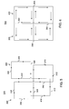
- FIG. 1 a diagram of a system for detecting merchandise surveillance markers constructed in accordance with the principles of the present invention and designated generally as "100".
- System 100 includes outer pane 102 of a door 104 comprising an inner window element 106.
- the outer pane 102 may be comprised of a conventional building material for a door such as wood or aluminum.
- the door 104 further includes a horizontal push bar 108 for pulling or pushing the door 104 open.
- the door 104 sits within and is hingably coupled to a threshold or door jam 110 via a pair of hinges 112 such that the door 104 may rotate about the hinges 112.
- FIG. 1 further shows a transceiver antenna 120 located on a bottom window pane of the door 104.
- the transceiver antenna 120 and its functions are described in greater detail below.
- the transceiver antenna 120 is connected to a transceiver controller 118 via a conductive element 115 consisting of a wire, cable or other conductive line.
- the transceiver controller 118 includes a current generator for sending a current or currents through the transceiver antenna 120, a detector for detecting signals received from the transceiver antenna 120 (due to the presence of a merchandise surveillance marker, such as an EAS marker or an RFID marker), and a processor for making alarm decisions.
- the transceiver antenna 120 includes a resonant or tuned RLC circuit.
- the tuned RLC circuit can be provided as part of transceiver controller 118.
- a loop 114 in the conductive element 115 allows the conductive element 115 to hang loosely around the section of the door 104 that rotates when the door 104 is opened or closed.
- an alarm 116 that, when activated by the transceiver controller 118 may produce an audible or visual indicator of the presence of a merchandise surveillance marker.
- the door 104 can be a side-hung swing door that is hung on either the left or right.
- the antenna 120 can be mounted on either face of the door 104, embedded within the door 104, mounted to one side of a checkout aisle, or mounted adjacent to or beneath a conveyor belt to detect the passage of merchandise surveillance markers.
- antennas 120 can be installed on each side of the double door.
- the transceiver antenna 120 can have separate transmitter and receiver coils.
- RFID Radio Frequency Identification
- the system 100 provides a method for detecting articles to which an RFID marker is affixed.
- RFID is an automatic identification method, relying on storing and remotely retrieving data using devices called RFID markers or transponders.
- An RFID marker is a small object that can be attached to or incorporated into a product, animal, or person.
- RFID markers contain silicon chips and antennas to enable them to receive and respond to radio-frequency queries from an RFID transceiver.
- RFID markers require no internal power source, whereas active markers require a power source.
- RFID markers can operate at low frequencies, such as 125 - 134.2 kHz and 140 - 148.5 kHz, high frequencies, such as 13.56 MHz, and ultra-high-frequencies, such as 868 MHz-928 MHz.
- the system 100 includes multiple directional or patch antennas 120 affixed to the door 104.
- a directional or patch antenna can comprise a conductive linear element such as a coil or a conductive planar element such as a metallic plate or shield.
- Phase canceling techniques can be used to produce the appropriate magnetic field for detecting corresponding merchandise surveillance markers.
- the controller 118 includes a current generator for sending a current or currents through the antenna 120, a detector for detecting signals received from the antenna 120, and a processor for making alarm decisions. When activated by the controller 118, the alarm 116 may produce an audible or visual indicator of the presence of a marker.
- various alternative types of antennas can be used for the antennas 120.
- FIG. 2 is a diagram showing a coordinate system 200 for identifying directions in an exemplary embodiment.
- directions refer to those directions defined in FIG. 2 .
- the horizontal direction 202 refers to the direction parallel to the plane of the door 104 and the plane of the floor 210.
- the outwards or lateral direction 206 refers to the direction parallel to the plane of the floor 210 and perpendicular to the plane of the door 104.
- the vertical direction 204 refers to the direction parallel to the plane of the door 104 and perpendicular to the plane of the floor 210.
- FIG. 3 is a diagram showing a first antenna 300 for use in a system for detecting merchandise surveillance markers, in one embodiment of the present invention.
- the antenna 300 comprises one half of the exemplary transceiver antenna 120 of FIG. 1 .
- a complete circuit is formed in one plane by the antenna 300, through which a current is sent from transceiver controller 118.
- the antenna 300 comprises a conductive element consisting of a wire, cable or other conductive line such that when a current is run through the conductive element, a corresponding magnetic field is produced.
- a figure-eight form of the antenna 300 includes two separate areas 320, 322 encompassed by two separate loops of the circuit of the antenna 300.
- the two separate areas 320, 322 encompassed by the circuit of the antenna 300 are of substantially the same size.
- the two separate areas 320, 322 encompassed by the circuit of the antenna 300 are of unequal size.
- FIG. 3 shows rectangular-shaped loops, the present invention supports other shapes, such as an ellipse, a circle, a pear shape, a kidney shape, etc.
- the two separate areas 320, 322 are of substantially unequal size.
- the smaller area would be encompassed by one or more additional coils or loops of the conductive element 115, thereby increasing the magnetic field strength produced by the smaller area, so as to make the magnetic field strengths produced by both areas 320, 322 substantially equal.
- smaller or reduced areas 320, 322 when operating at ultra-high-frequencies, such as 868 MHz-928 MHz, produce a magnetic field commensurate with larger areas 320, 322 used with lower frequency settings. In this way, the size of areas 320, 322 can be modified to larger or smaller magnitudes, while still producing similar magnetic field strengths, as long as the operating frequency of the antenna 300 is modified accordingly.
- FIG. 3 Also shown in FIG. 3 are a series of arrows showing current flow within the antenna 300.
- the arrows show that current flows up the circuit segment 302, turns to the left through circuit segment 304, turns downward on circuit segment 306, turns to the right on circuit segment 308, turns downward on circuit segment 310 and turns to the left on circuit segment 312 to complete the circuit.
- the conductive element forming segment 302 is positioned around the conductive element forming segment 308 to avoid creating a short circuit.
- the configuration of the current flow results in a magnetic flux exiting in the opposite direction for area 320 as compared to 322.
- FIG. 4 is a diagram showing a second antenna 400 for use in a system for detecting merchandise surveillance markers.
- the antenna 400 comprises the other half of the exemplary transceiver antenna 120 shown in FIG. 1 .
- a complete circuit is formed in one plane by the antenna 400, through which a current is sent from transceiver controller 118.
- the antenna 400 comprises a conductive element.
- the two separate areas 420, 422 encompassed by the circuit of the antenna 400 are of substantially the same size.
- the two separate areas 420, 422 encompassed by the circuit of the antenna 400 are of unequal size.
- the two separate areas 420, 422 encompassed by the circuit of the antenna 400 are of equal size to areas 320, 322 of FIG. 3 .
- the two separate areas 420, 422 are of substantially unequal size.
- the smaller area would be encompassed by one or more additional coils or loops of the conductive element 115, thereby increasing the magnetic field strength produced by the smaller area, so as to make the magnetic field strengths produced by both areas 420, 422 substantially equal.
- FIG. 4 Also shown in FIG. 4 are a series of arrows showing current flow within the antenna 400.
- the arrows indicate that current flows up the circuit segment 402, turns to the right through circuit segment 404, turns downward on circuit segment 406, turns to the left on circuit segment 408, turns downward on circuit segment 410 and turns to the right on circuit segment 412 to complete the circuit.
- conductive element forming segment 402 is positioned around segment 408 to avoid creating a short circuit.
- the configuration of the current flow results in a magnetic flux exiting in the opposite direction-from area 420 as compared to 422.
- FIG. 5 is a diagram showing the first antenna 300 of FIG. 3 and the second antenna 400 of FIG. 4 integrated into single transceiver 500 for use in a system for detecting merchandise surveillance markers, in one embodiment of the present invention.
- FIG. 5 shows antennas 300, 400 superimposed on each other in a substantially coplanar manner such that both antennas 300 and 400 occupy the same overall area.
- FIG. 5 depicts the two antennas 300, 400 slightly offset so as to better show current flow arrows.
- antennas 300 and 400 are actually positioned so that the two antennas are orthogonally oriented (rotated approximately 90 degrees) with respect to one another.
- antenna 300 is placed on top of or overlaid onto antenna 400, while in another embodiment antenna 400 is placed on top of antenna 300.
- FIG. 5 shows that circuit segments 302 and 402 have current flow in the same direction which would amplify the magnetic flux emanating from the area surrounding circuit segments 302 and 402.
- FIG. 5 shows that circuit segments 308 and 408 have current flow in the opposite direction which would cancel or zero out the magnetic flux emanating from the area surrounding circuit segments 308 and 408.
- the two antennas are positioned so that the two antennas are orthogonally oriented (rotated approximately 90 degrees) with respect to one another. All other magnetic fields remain as described with respect to FIGS. 3 and 4 above.
- the end result of stacking antenna 300 and 400 together is an overall magnetic flux identical to the magnetic flux each antenna transmits alone, with the exception of: a) a reduction or elimination of magnetic flux in the area surrounding circuit segments 308 and 408 and b) a magnification of magnetic flux in the area surrounding circuit segments 302 and 402.
- FIG. 6 is a diagram showing another view of the single transceiver 500 of FIG. 5.
- FIG. 6 depicts the two antennas 300, 400 stacked and aligned with each other, as opposed to slightly offset as in FIG. 5 .
- the arrows in FIG. 6 show current flow within each circuit segment.
- the resultant magnetic field produced by the single transceiver 500 is an overall magnetic flux as described for each antenna, with the exception of a reduction of magnetic flux in the area surrounding circuit segments 308 and 408 and a magnification of magnetic flux in the area surrounding circuit segments 302 and 402.
- the controller 118 periodically changes the direction of the current running through one antenna segment with respect to the other antenna segment so as to periodically alternate those areas having reduced and magnified magnetic flux. For example, if controller 118 switches the current running through antenna 300 to the opposite direction as depicted in FIG 5 , then the resultant magnetic field produced by the single transceiver 500 would be the overall magnetic flux as described above for FIG. 5 , with the exception of a magnification of magnetic flux in the area surrounding circuit segments 308 and 408 (since current would be running in the same direction in both segments) and a reduction or elimination of magnetic flux in the area surrounding circuit segments 302 and 402 (since current would be running in the opposite direction in both segments).
- segment 302, 402 periodically alternates between reduced magnetic flux and amplified magnetic flux - likewise, segment 308, 408 periodically alternates between reduced magnetic flux and amplified magnetic flux.
- segment 308, 408 periodically alternates between reduced magnetic flux and amplified magnetic flux.
- the weak part of the magnetic field i.e., that section of the single transceiver 500 where collinear circuit segments run current in opposite directions
- the magnetic field produced by the system 100 can minimize the exposure of the weak magnetic field and optimize its ability to detect merchandise surveillance markers.
- FIG. 7 is a diagram showing a first antenna 700 for use in a system for detecting merchandise surveillance markers, according to the principles of the present invention.
- the antenna 700 may comprise one half of the exemplary transceiver antenna 120 of FIG. 1 .
- a complete circuit is formed in one plane by the antenna 700, through which a current is sent from transceiver controller 118.
- the antenna 700 comprises a conductive element.
- the substantially figure-eight form of the antenna 700 is also shown.
- the two separate areas 720, 722 encompassed by the circuit of the antenna 700 are of substantially the same size.
- the two separate areas 720, 722 encompassed by the circuit of the antenna 700 are of unequal size.
- FIG. 3 shows rectangular-shaped loops, the present invention supports other shapes, such as an ellipse, a circle, a pear shape, a kidney shape, etc.
- the angle 726 between the two areas 720, 722 is greatly exaggerated for purposes of showing current flow arrows.
- the actual angle 726 between the two areas 720, 722 may be substantially zero so as to appear as two rectangles adjacent to each other.
- FIG. 7 Also shown in FIG. 7 is a series of arrows showing current flow within the antenna 700.
- the arrows show that current flows up the circuit segment 702, turns to the left through circuit segment 704, turns downward on circuit segment 706, turns to the right on circuit segment 708, turns downward on circuit segment 710, turns to the left on circuit segment 712, turns upwards on circuit segment 714 and turns to the right on segment 716 to complete the circuit.
- the conductive element forming segment 716 is positioned around the conductive element forming segment 708 to avoid creating a short circuit.
- the configuration of the current flow results in a magnetic flux exiting in the opposite direction from area 720 as compared to 722.
- FIG. 8 is a diagram showing a second antenna 800 for use in a system for detecting merchandise surveillance markers, in one embodiment of the present invention.
- the antenna 800 comprises the other half of the exemplary transceiver antenna 120 of FIG. 1 .
- a complete circuit is formed in one plane by the antenna 800, through which a current is sent from transceiver controller 118.
- the antenna 800 comprises a conductive element.
- the substantially figure-eight form of the antenna 800 similar to antenna 700.
- the two separate areas 820, 822 encompassed by the circuit of the antenna 800 are of substantially the same size.
- the two separate areas 820, 822 encompassed by the circuit of the antenna 800 are of unequal size.
- the two separate areas 820, 822 encompassed by the circuit of the antenna 800 are of equal size to areas 720, 722 of FIG. 7 .
- FIG. 8 Also shown in FIG. 8 are a series of arrows showing current flow within the antenna 800.
- the arrows show that current flows up the circuit segment 802, turns to the left through circuit segment 804, turns downward on circuit segment 806, turns to the right on circuit segment 808, turns upward on circuit segment 810, turns to the right on circuit segment 812, turns downwards on circuit segment 814 and turns to the left on segment 816 to complete the circuit.
- the conductive element forming segment 802 is positioned around the conductive element forming segment 810. The configuration of the current flow results in a magnetic flux radiating in the opposite direction from area 820 as compared with area 822.
- FIG. 9 is a diagram showing the first antenna 700 of FIG. 7 and the second antenna 800 of FIG. 8 integrated into single transceiver 900 for use in a system for detecting merchandise surveillance markers, in one embodiment of the present invention.
- FIG. 9 shows antennas 700, 800 superimposed on each other in a substantially coplanar manner such that both antennas 700 and 800 occupy the same overall area.
- FIG. 9 depicts the two antennas 700, 800 slightly offset so as to better show current flow arrows. As is shown, the two antennas 700 and 800 are positioned so that the two antennas are orthogonally oriented (rotated approximately 90 degrees) with respect to one another.
- antenna 700 is placed on top of or overlaid onto antenna 700, while in another embodiment antenna 800 is placed on top of antenna 700.
- antenna 700 is placed on top of and aligned with antenna 800, while in another embodiment antenna 800 is placed on top of and aligned with antenna 700 (see FIG. 9 below for a more detailed description of this embodiment).
- FIG. 9 shows that circuit segments 804 and 704, as well as circuit segments 706 and 806 have current flow in the same direction which would amplify the magnetic flux emanating from the area surrounding these circuit segments.
- FIG. 9 also shows that circuit segments 806 and 714 as well as 808 and 712 have current flow in the opposite direction which would cancel or zero out the magnetic flux emanating from the area surrounding these circuit segments.
- antennas 700 and 800 shaped with segments 708, 716, 802 and 810 forming obtuse angles with respect to their corresponding outer walls, e.g., segments 702 and 706, subject to the bend radius of the wires forming the circuit, it is contemplated that segments 708, 716, 802 and 810 can also be arranged to substantially form right angles with respect to outer wall segments. Accordingly, it is noted that the shape of antennas 700 and 800 as shown in FIGS. 7-9 is for illustrative purposes only.
- circuit segments 812 and 704 as well as 814 and 702 have current flow in the opposite direction, thereby canceling out the magnetic flux in these areas, and circuit segments 814 and 710, as well as circuit segments 712 and 816 have current flow in the same direction, thereby amplifying the magnetic flux in these areas. Also, since circuit segments 708 and 716, as well as 810 and 802 are substantially collinear, the magnetic flux in these areas is amplified.
- the resultant magnetic field produced by the single transceiver 900 includes: a) an amplified magnetic flux around the inside segments of all quadrants of the single transceiver 900, b) a null or reduced magnetic field in the outer segments of the upper right and lower left quadrants and c) a magnetic field produced by one antenna in all other areas of the single transceiver 900.
- the controller 118 periodically changes the direction of the current running through one antenna so as to periodically alternate those areas having reduced and magnified magnetic flux. For example, if controller 118 switches the current running through antenna 700 to the opposite direction as depicted in FIG 7 , then the resultant magnetic field produced by the single transceiver 900 would include: a) an amplified magnetic flux around the inside segments of all quadrants of the single transceiver 900, b) a null or reduced magnetic field in the outer segments of the upper left and lower right quadrants and c) a magnetic field produced by one antenna in all other areas of the single transceiver 900.
- the outer segments of the upper right and lower left quadrants periodically alternate between reduced magnetic flux and amplified magnetic flux - likewise, the outer segments of the upper left and lower right quadrants periodically alternates between reduced magnetic flux and amplified magnetic flux.
- the embodiments of the present invention allow for the production of a "focused" magnetic field strong enough to detect merchandise surveillance markers but having an amplitude that is low enough to avoid the detection of merchandise surveillance markers that may be situated near the detector, as in a small retail store where floor space is largely reduced. Further, the embodiments of the present invention advantageously allow for the production of an adequate magnetic field using reduced power and a small antenna footprint.
- figure-eight conductive elements or coils increases the detection capability of the merchandise surveillance system 100.
- Distant signal sources affect both halves of a figure-eight coil equally, thereby creating opposing currents in either half of the coil, which cancel themselves out.
- environmental signal sources cancel themselves out, whereas a merchandise surveillance marker that is close to the magnetic field will normally be closer to one loop than another, thereby inducing a larger current in one coil, resulting in a detection. Therefore, merchandise surveillance markers near the magnetic field have an improved signal-to-noise ratio over environmental noise.
- the use of figure-eight conductive elements or coils as transmitters decreases interference potential since the field from each half of the coil will be roughly equal from a large distance, but out of phase, and will therefore self-cancel.
- the embodiments of the present invention are also beneficial for the mounting of a system 100 onto a door 104 having a metal frame as de-tuning of the magnetic field is reduced or eliminated.
- Magnetic flux from one half of an antenna (such as half 320 of antenna 300) generates a current in the door frame 102 in the direction opposite of the current in that half of the antenna 300.
- magnetic flux from the other half of the antenna (such as half 322 of antenna 300) generates a current in the door frame 102 in the other direction, thereby canceling out the previous current induced in the door frame 102.
- the weak part of the magnetic field i.e., that section of the single transceiver 900 where collinear circuit segments run current in opposite directions is mitigated by alternately emanating a weak (or non-existent) and a magnified magnetic field.
- the magnetic field produced by the system 100 can minimize the exposure of the weak magnetic field and optimize its ability to detect merchandise surveillance markers.
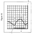
- FIG. 10 is a graph showing magnetic field strength for a single antenna 700 in the vertical direction 204 (see FIG. 2 ).
- the graph of FIG. 10 shows height on the y-axis 1002 and magnetic field strength on the x-axis 1004.
- the placement of the antenna 700 is shown at 1006.
- the graph shows that the field strength of the antenna 700 peaks 1010 mid-way up the antenna 300 and tapers off at the top and bottom edges 1012, 1014 of the antenna 700.
- FIG. 11 is a graph showing magnetic field strength for a single antenna 700 in the horizontal direction 202.
- the graph of FIG. 11 shows horizontal distance on the y-axis 1102 and magnetic field strength on the x-axis 1104.
- the placement of the antenna 700 is shown at 1106.
- the graph shows that the field strength of the antenna 700 exhibits a valley 1110 mid-way across the antenna 700 and tapers off at the side edges 1112, 1114 of the antenna 700.
- FIG. 12 is a graph showing magnetic field strength for a single antenna 700 in the lateral direction 206.
- the graph of FIG. 12 shows lateral distance on the y-axis 1202 and magnetic field strength on the x-axis 1204.
- the placement of the antenna 700 is shown at 1206.
- the graph shows that the field strength of the antenna 700 is high 1210 at the antenna 700, exhibits a valley 1212 at a certain distance from the antenna 700, increases 1214 after the valley and subsequently tapers off 1216 as the distance from the antenna 700 continues to increase.
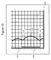
- FIG. 13 is a graph showing magnetic field strength for a compound transceiver antenna 900 (such as the compound antenna shown in FIG. 6 ) in the vertical direction 204 (see FIG. 2 ).
- the graph of FIG. 13 shows height on the y-axis 1302 and magnetic field strength on the x-axis 1304.
- the placement of the antenna 900 is shown at 1306.
- the graph shows that the field strength of the antenna 900 peaks 1310 mid-way up the antenna 900 and decreases but remains substantial at the top and bottom edges 1312, 1314 of the antenna 900. Comparing the graph of FIG. 13 to the graph of FIG. 10 shows increased magnetic field strength at the top and bottom edges 1312, 1314 of the antenna 900.
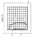
- FIG. 14 is a graph showing magnetic field strength for a compound transceiver antenna 900 in the horizontal direction 202.
- the graph of FIG. 14 shows horizontal distance on the y-axis 1402 and magnetic field strength on the x-axis 1404.
- the placement of the antenna 900 is shown at 1406.
- the graph shows that the field strength of the antenna 900 is relatively constant across the antenna 900 and tapers off slightly at the side edges 1412, 1414 of the antenna 900. Comparing the graph of FIG. 14 to the graph of FIG. 11 shows that valley 1110 (in FIG. 11 ) is gone in FIG. 14.
- FIG. 14 shows a more uniform field strength than that shown in FIG. 11 .
- FIG. 15 is a graph showing magnetic field strength for a compound transceiver antenna 900 in the lateral direction 206.
- the graph of FIG. 15 shows lateral distance on the y-axis 1502 and magnetic field strength on the x-axis 1504.
- the placement of the antenna 900 is shown at 1506.
- the graph shows that the field strength of the antenna 900 is almost constant within a range of distance from the antenna 900, except for a narrow valley 1512 at a certain distance from the antenna 900. Comparing the graph of FIG. 15 to the graph of FIG. 12 shows increased magnetic field strength at all distances from the antenna 900 except for a narrow valley 1512.
Landscapes
- Engineering & Computer Science (AREA)
- Physics & Mathematics (AREA)
- Signal Processing (AREA)
- Automation & Control Theory (AREA)
- Computer Security & Cryptography (AREA)
- Electromagnetism (AREA)
- General Physics & Mathematics (AREA)
- Burglar Alarm Systems (AREA)
- Near-Field Transmission Systems (AREA)
Claims (8)
- Sendeempfänger (120) zum Detektieren einer Warenmarkierung, der Folgendes umfasst:eine erste Antenne (300), die eine erste Schaltung mit einer ersten Schleife, die einen ersten Bereich (320) definiert, und einer zweiten Schleife, die einen zweiten Bereich (322), der zu dem ersten Bereich (320) koplanar ist, definiert, umfasst; undeine zweite Antenne (400), die in Bezug auf die erste Antenne (300) koplanar ist, wobei die zweite Antenne (400) eine zweite Schaltung mit einer dritten Schleife, die einen dritten Bereich (420) definiert, und einer vierten Schleife, die einen vierten Bereich (422), der zu dem dritten Bereich (420) koplanar ist, definiert, umfasst, wobei sowohl die erste Antenne (300) als auch die zweite Antenne (400) die Konstellation einer Acht haben,dadurch gekennzeichnet, dassdie erste Antenne (300) und die zweite Antenne (400) in Bezug auf ihre Konstellationen einer Acht durch eine Drehung um 90° und in einer gestapelten Beziehung senkrecht ausgerichtet sind; und der Sendeempfänger (120) ferner Folgendes umfasst:eine Steuereinheit (118) zum Senden eines Stroms sowohl durch die erste (300) als auch die zweite Antenne (400),wobei die Steuereinheit (118) konfiguriert ist, eine Richtung des durch eine der ersten und der zweiten Schaltung geschickten Stroms zu ändern, um den magnetischen Fluss in einem Bereich, der ein erstes Paar paralleler Schaltungssegmente (308, 408) der ersten und der zweiten Antenne (300, 400) umgibt, zu verringern oder zu beseitigen und den magnetischen Fluss in einem Bereich, der ein zweites Paar Schaltungselemente (302, 402) der Antennen (300, 400), die senkrecht zu dem ersten Paar Schaltungssegmente (308, 408) ausgerichtet sind, umgibt, zu verstärken und umgekehrt, indem sie in dem ersten Paar Schaltungssegmente (308, 408) einen Stromfluss in der entgegengesetzten Richtung bereitstellt und in dem zweiten Paar Schaltungssegmente (302, 402) einen Stromfluss in derselben Richtung bereitstellt,wobei der gesamte magnetische Fluss bis auf die Verringerung oder Beseitigung und Verstärkung identisch zu dem magnetischen Fluss gelassen wird, den jede Antenne (300, 400) allein sendet.
- Sendeempfänger nach Anspruch 1, wobei der erste Bereich (320) im Wesentlichen von der gleichen Größe wie der zweite Bereich (322) ist.
- Sendeempfänger nach Anspruch 2, wobei der dritte Bereich (420) im Wesentlichen von der gleichen Größe wie der vierte Bereich (422) ist.
- Sendeempfänger nach Anspruch 3, wobei der erste Bereich (320) und der zweite Bereich (322) im Wesentlichen von der gleichen Größe wie der dritte Bereich (420) und der vierte Bereich (422) sind.
- Sendeempfänger nach Anspruch 1, wobei die Warenmarkierung eine EAS-Markierung oder eine RFID-Markierung umfasst.
- Sendeempfänger nach Anspruch 1, wobei die erste Antenne (300) und die zweite Antenne (400) Richtantennen sind.
- Sendeempfänger nach Anspruch 1, der ferner einen Detektor umfasst, wobei der Detektor konfiguriert ist, die Warenmarkierung durch Empfangen eines Signals von der ersten oder der zweiten Antenne zu detektieren.
- Sendeempfänger nach Anspruch 1, der ferner Folgendes umfasst: einen Alarm (116), wobei der Alarm konfiguriert ist, einen Indikator zu aktivieren, wenn die Warenmarkierung durch den Detektor detektiert wird.
Applications Claiming Priority (2)
| Application Number | Priority Date | Filing Date | Title |
|---|---|---|---|
| US11/507,920 US7733290B2 (en) | 2005-12-19 | 2006-08-22 | Merchandise surveillance system antenna and method |
| PCT/US2007/018602 WO2008024421A2 (en) | 2006-08-22 | 2007-08-22 | Merchandise surveillance system antenna and method |
Publications (2)
| Publication Number | Publication Date |
|---|---|
| EP2054971A2 EP2054971A2 (de) | 2009-05-06 |
| EP2054971B1 true EP2054971B1 (de) | 2016-02-24 |
Family
ID=39016255
Family Applications (1)
| Application Number | Title | Priority Date | Filing Date |
|---|---|---|---|
| EP07837229.9A Active EP2054971B1 (de) | 2006-08-22 | 2007-08-22 | Antenne und verfahren für ein warenüberwachungssystem |
Country Status (9)
| Country | Link |
|---|---|
| US (1) | US7733290B2 (de) |
| EP (1) | EP2054971B1 (de) |
| JP (1) | JP5397815B2 (de) |
| CN (1) | CN101529653B (de) |
| AR (1) | AR062489A1 (de) |
| AU (1) | AU2007288186B2 (de) |
| CA (1) | CA2661472C (de) |
| ES (1) | ES2566059T3 (de) |
| WO (1) | WO2008024421A2 (de) |
Families Citing this family (6)
| Publication number | Priority date | Publication date | Assignee | Title |
|---|---|---|---|---|
| KR101394437B1 (ko) * | 2007-09-21 | 2014-05-14 | 삼성전자주식회사 | 아이솔레이션 특성을 향상시키는 멀티밴드 안테나 및 멀티밴드 안테나 시스템 |
| JP2013005252A (ja) * | 2011-06-17 | 2013-01-07 | Elpida Memory Inc | 通信装置 |
| WO2013117994A1 (en) * | 2012-01-05 | 2013-08-15 | Hid Global Gmbh | Calculated compensated magnetic antennas for different frequencies |
| US10157337B1 (en) * | 2017-06-16 | 2018-12-18 | Amazon Technologies, Inc. | Pre-notification with RFID dock door portals |
| US10395074B1 (en) * | 2018-09-28 | 2019-08-27 | Auden Techno Corp. | RFID reader and antenna structure thereof |
| KR102236706B1 (ko) * | 2020-01-10 | 2021-04-05 | 경상국립대학교산학협력단 | 근거리 루프 안테나 |
Family Cites Families (21)
| Publication number | Priority date | Publication date | Assignee | Title |
|---|---|---|---|---|
| US4135183A (en) * | 1977-05-24 | 1979-01-16 | Minnesota Mining And Manufacturing Company | Antipilferage system utilizing "figure-8" shaped field producing and detector coils |
| NL8602033A (nl) | 1986-08-08 | 1988-03-01 | Nedap Nv | Precisie richtfunctie bij herkensysteem. |
| US5142292A (en) * | 1991-08-05 | 1992-08-25 | Checkpoint Systems, Inc. | Coplanar multiple loop antenna for electronic article surveillance systems |
| BR9609286A (pt) * | 1995-05-30 | 1999-05-11 | Sensormatic Electronics Corp | Configuração de antena de sistema eas para proporcionar melhor distribuição de campo de interrogação |
| US5815076A (en) * | 1996-01-16 | 1998-09-29 | Sensormatic Electronics Corporation | Pulsed-signal magnetomechanical electronic article surveillance system with improved damping of transmitting antenna |
| JP4071858B2 (ja) * | 1998-05-01 | 2008-04-02 | 吉川アールエフシステム株式会社 | リーダライタ用アンテナ装置 |
| JP2000315908A (ja) * | 1999-04-30 | 2000-11-14 | Toppan Forms Co Ltd | アンテナ接続体とその製造方法 |
| US6249229B1 (en) * | 1999-08-16 | 2001-06-19 | Checkpoint Systems, Inc., A Corp. Of Pennsylvania | Electronic article security system employing variable time shifts |
| CA2303703C (en) * | 2000-03-30 | 2001-09-04 | James Stanley Podger | The lemniscate antenna element |
| CA2347596C (en) * | 2001-05-17 | 2004-01-27 | James Stanley Podger | The double-lemniscate antenna element |
| JP2002368525A (ja) * | 2001-06-11 | 2002-12-20 | Ajinomoto Co Inc | アンテナコイル |
| US6822570B2 (en) | 2001-12-20 | 2004-11-23 | Calypso Medical Technologies, Inc. | System for spatially adjustable excitation of leadless miniature marker |
| JP4069377B2 (ja) * | 2002-12-17 | 2008-04-02 | 三菱マテリアル株式会社 | リーダ/ライタアンテナ及び該アンテナを備えるrfidシステム |
| JP2005026989A (ja) * | 2003-07-01 | 2005-01-27 | Toshiba Corp | アンテナ装置および非接触icカードリーダライタ装置 |
| CA2476511A1 (en) * | 2003-08-04 | 2005-02-04 | Frank Hader | Store security tag detector |
| JP2005102101A (ja) * | 2003-09-01 | 2005-04-14 | Matsushita Electric Ind Co Ltd | ゲートアンテナ装置 |
| FR2864354B1 (fr) * | 2003-12-17 | 2006-03-24 | Commissariat Energie Atomique | Antenne plane a champ tournant, comportant une boucle centrale et des boucles excentrees, et systeme d'identification par radiofrequence |
| US7109866B2 (en) * | 2004-01-23 | 2006-09-19 | Sensormatic Electronics Corporation | Electronic article surveillance marker deactivator using an expanded detection zone |
| CN1292390C (zh) * | 2004-10-20 | 2006-12-27 | 华南理工大学 | 数字式电子标签的检测方法 |
| JP2006287659A (ja) * | 2005-03-31 | 2006-10-19 | Tdk Corp | アンテナ装置 |
| US7551080B2 (en) * | 2006-07-17 | 2009-06-23 | Sensormatic Electronics Corporation | Control for embedded and door-mounted antennas |
-
2006
- 2006-08-22 US US11/507,920 patent/US7733290B2/en active Active
-
2007
- 2007-08-22 JP JP2009525623A patent/JP5397815B2/ja active Active
- 2007-08-22 AR ARP070103734A patent/AR062489A1/es active IP Right Grant
- 2007-08-22 CN CN200780038469.2A patent/CN101529653B/zh active Active
- 2007-08-22 AU AU2007288186A patent/AU2007288186B2/en active Active
- 2007-08-22 EP EP07837229.9A patent/EP2054971B1/de active Active
- 2007-08-22 ES ES07837229.9T patent/ES2566059T3/es active Active
- 2007-08-22 CA CA2661472A patent/CA2661472C/en active Active
- 2007-08-22 WO PCT/US2007/018602 patent/WO2008024421A2/en active Application Filing
Also Published As
| Publication number | Publication date |
|---|---|
| US20080068273A1 (en) | 2008-03-20 |
| WO2008024421A3 (en) | 2008-04-17 |
| WO2008024421A2 (en) | 2008-02-28 |
| EP2054971A2 (de) | 2009-05-06 |
| AU2007288186A1 (en) | 2008-02-28 |
| AU2007288186B2 (en) | 2012-03-08 |
| CA2661472C (en) | 2014-06-03 |
| AR062489A1 (es) | 2008-11-12 |
| US7733290B2 (en) | 2010-06-08 |
| CN101529653A (zh) | 2009-09-09 |
| JP2010501935A (ja) | 2010-01-21 |
| JP5397815B2 (ja) | 2014-01-22 |
| CA2661472A1 (en) | 2008-02-28 |
| ES2566059T3 (es) | 2016-04-08 |
| CN101529653B (zh) | 2017-04-19 |
Similar Documents
| Publication | Publication Date | Title |
|---|---|---|
| US9342968B2 (en) | Electronic article surveillance systems implementing methods for determining security tag locations | |
| KR100431425B1 (ko) | 송수신용루프안테나 | |
| EP2054971B1 (de) | Antenne und verfahren für ein warenüberwachungssystem | |
| JP4797071B2 (ja) | 広い出入り口に対応した電子物品監視用アンテナシステム | |
| EP3201888B1 (de) | Systeme und verfahren zur intrazonendetektion | |
| EP2543025B1 (de) | Verfahren und vorrichtung zur reduzierung der interferenzwirkung in integrierten systemen zur metallerkennung/überwachung elektronischer artikel | |
| US5877728A (en) | Multiple loop antenna | |
| JPH06342065A (ja) | 電子式物品監視システム及び方法 | |
| US8451126B2 (en) | Combination electronic article surveillance/radio frequency identification antenna and method | |
| US20120212343A1 (en) | Point of entry deactivation | |
| EP3347881B1 (de) | Systeme und verfahren für variable detektion auf der grundlage einer verkehrszählereingabe | |
| EP1138098A1 (de) | Mehrfach-schleifenantenne | |
| JPH10208163A (ja) | 電子式保安システムのためのアンテナシステム | |
| EP3178075A1 (de) | Systeme und verfahren zur adaptiven steuerung eines senderfeldes | |
| AU2014208265A1 (en) | Combination electronic article surveillance/radio frequency identification antenna |
Legal Events
| Date | Code | Title | Description |
|---|---|---|---|
| PUAI | Public reference made under article 153(3) epc to a published international application that has entered the european phase |
Free format text: ORIGINAL CODE: 0009012 |
|
| 17P | Request for examination filed |
Effective date: 20090316 |
|
| AK | Designated contracting states |
Kind code of ref document: A2 Designated state(s): AT BE BG CH CY CZ DE DK EE ES FI FR GB GR HU IE IS IT LI LT LU LV MC MT NL PL PT RO SE SI SK TR |
|
| DAX | Request for extension of the european patent (deleted) | ||
| 17Q | First examination report despatched |
Effective date: 20110119 |
|
| RAP1 | Party data changed (applicant data changed or rights of an application transferred) |
Owner name: SENSORMATIC ELECTRONICS, LLC |
|
| RAP1 | Party data changed (applicant data changed or rights of an application transferred) |
Owner name: TYCO FIRE & SECURITY GMBH |
|
| GRAP | Despatch of communication of intention to grant a patent |
Free format text: ORIGINAL CODE: EPIDOSNIGR1 |
|
| RIC1 | Information provided on ipc code assigned before grant |
Ipc: G08B 13/24 20060101ALI20150929BHEP Ipc: H01Q 1/22 20060101ALI20150929BHEP Ipc: H01Q 7/04 20060101AFI20150929BHEP |
|
| INTG | Intention to grant announced |
Effective date: 20151021 |
|
| GRAS | Grant fee paid |
Free format text: ORIGINAL CODE: EPIDOSNIGR3 |
|
| GRAA | (expected) grant |
Free format text: ORIGINAL CODE: 0009210 |
|
| STAA | Information on the status of an ep patent application or granted ep patent |
Free format text: STATUS: THE PATENT HAS BEEN GRANTED |
|
| AK | Designated contracting states |
Kind code of ref document: B1 Designated state(s): AT BE BG CH CY CZ DE DK EE ES FI FR GB GR HU IE IS IT LI LT LU LV MC MT NL PL PT RO SE SI SK TR |
|
| REG | Reference to a national code |
Ref country code: GB Ref legal event code: FG4D |
|
| REG | Reference to a national code |
Ref country code: CH Ref legal event code: EP |
|
| REG | Reference to a national code |
Ref country code: AT Ref legal event code: REF Ref document number: 777163 Country of ref document: AT Kind code of ref document: T Effective date: 20160315 |
|
| REG | Reference to a national code |
Ref country code: IE Ref legal event code: FG4D |
|
| REG | Reference to a national code |
Ref country code: DE Ref legal event code: R096 Ref document number: 602007044992 Country of ref document: DE |
|
| REG | Reference to a national code |
Ref country code: ES Ref legal event code: FG2A Ref document number: 2566059 Country of ref document: ES Kind code of ref document: T3 Effective date: 20160408 |
|
| REG | Reference to a national code |
Ref country code: LT Ref legal event code: MG4D |
|
| REG | Reference to a national code |
Ref country code: NL Ref legal event code: MP Effective date: 20160224 |
|
| REG | Reference to a national code |
Ref country code: AT Ref legal event code: MK05 Ref document number: 777163 Country of ref document: AT Kind code of ref document: T Effective date: 20160224 |
|
| PG25 | Lapsed in a contracting state [announced via postgrant information from national office to epo] |
Ref country code: FI Free format text: LAPSE BECAUSE OF FAILURE TO SUBMIT A TRANSLATION OF THE DESCRIPTION OR TO PAY THE FEE WITHIN THE PRESCRIBED TIME-LIMIT Effective date: 20160224 Ref country code: IT Free format text: LAPSE BECAUSE OF FAILURE TO SUBMIT A TRANSLATION OF THE DESCRIPTION OR TO PAY THE FEE WITHIN THE PRESCRIBED TIME-LIMIT Effective date: 20160224 Ref country code: GR Free format text: LAPSE BECAUSE OF FAILURE TO SUBMIT A TRANSLATION OF THE DESCRIPTION OR TO PAY THE FEE WITHIN THE PRESCRIBED TIME-LIMIT Effective date: 20160525 |
|
| REG | Reference to a national code |
Ref country code: FR Ref legal event code: PLFP Year of fee payment: 10 |
|
| PG25 | Lapsed in a contracting state [announced via postgrant information from national office to epo] |
Ref country code: NL Free format text: LAPSE BECAUSE OF FAILURE TO SUBMIT A TRANSLATION OF THE DESCRIPTION OR TO PAY THE FEE WITHIN THE PRESCRIBED TIME-LIMIT Effective date: 20160224 Ref country code: SE Free format text: LAPSE BECAUSE OF FAILURE TO SUBMIT A TRANSLATION OF THE DESCRIPTION OR TO PAY THE FEE WITHIN THE PRESCRIBED TIME-LIMIT Effective date: 20160224 Ref country code: AT Free format text: LAPSE BECAUSE OF FAILURE TO SUBMIT A TRANSLATION OF THE DESCRIPTION OR TO PAY THE FEE WITHIN THE PRESCRIBED TIME-LIMIT Effective date: 20160224 Ref country code: LV Free format text: LAPSE BECAUSE OF FAILURE TO SUBMIT A TRANSLATION OF THE DESCRIPTION OR TO PAY THE FEE WITHIN THE PRESCRIBED TIME-LIMIT Effective date: 20160224 Ref country code: LT Free format text: LAPSE BECAUSE OF FAILURE TO SUBMIT A TRANSLATION OF THE DESCRIPTION OR TO PAY THE FEE WITHIN THE PRESCRIBED TIME-LIMIT Effective date: 20160224 Ref country code: PT Free format text: LAPSE BECAUSE OF FAILURE TO SUBMIT A TRANSLATION OF THE DESCRIPTION OR TO PAY THE FEE WITHIN THE PRESCRIBED TIME-LIMIT Effective date: 20160624 Ref country code: PL Free format text: LAPSE BECAUSE OF FAILURE TO SUBMIT A TRANSLATION OF THE DESCRIPTION OR TO PAY THE FEE WITHIN THE PRESCRIBED TIME-LIMIT Effective date: 20160224 |
|
| PG25 | Lapsed in a contracting state [announced via postgrant information from national office to epo] |
Ref country code: DK Free format text: LAPSE BECAUSE OF FAILURE TO SUBMIT A TRANSLATION OF THE DESCRIPTION OR TO PAY THE FEE WITHIN THE PRESCRIBED TIME-LIMIT Effective date: 20160224 Ref country code: EE Free format text: LAPSE BECAUSE OF FAILURE TO SUBMIT A TRANSLATION OF THE DESCRIPTION OR TO PAY THE FEE WITHIN THE PRESCRIBED TIME-LIMIT Effective date: 20160224 |
|
| REG | Reference to a national code |
Ref country code: DE Ref legal event code: R097 Ref document number: 602007044992 Country of ref document: DE |
|
| PG25 | Lapsed in a contracting state [announced via postgrant information from national office to epo] |
Ref country code: RO Free format text: LAPSE BECAUSE OF FAILURE TO SUBMIT A TRANSLATION OF THE DESCRIPTION OR TO PAY THE FEE WITHIN THE PRESCRIBED TIME-LIMIT Effective date: 20160224 Ref country code: CZ Free format text: LAPSE BECAUSE OF FAILURE TO SUBMIT A TRANSLATION OF THE DESCRIPTION OR TO PAY THE FEE WITHIN THE PRESCRIBED TIME-LIMIT Effective date: 20160224 Ref country code: SK Free format text: LAPSE BECAUSE OF FAILURE TO SUBMIT A TRANSLATION OF THE DESCRIPTION OR TO PAY THE FEE WITHIN THE PRESCRIBED TIME-LIMIT Effective date: 20160224 |
|
| PG25 | Lapsed in a contracting state [announced via postgrant information from national office to epo] |
Ref country code: BE Free format text: LAPSE BECAUSE OF FAILURE TO SUBMIT A TRANSLATION OF THE DESCRIPTION OR TO PAY THE FEE WITHIN THE PRESCRIBED TIME-LIMIT Effective date: 20160224 |
|
| PLBE | No opposition filed within time limit |
Free format text: ORIGINAL CODE: 0009261 |
|
| STAA | Information on the status of an ep patent application or granted ep patent |
Free format text: STATUS: NO OPPOSITION FILED WITHIN TIME LIMIT |
|
| 26N | No opposition filed |
Effective date: 20161125 |
|
| PG25 | Lapsed in a contracting state [announced via postgrant information from national office to epo] |
Ref country code: BG Free format text: LAPSE BECAUSE OF FAILURE TO SUBMIT A TRANSLATION OF THE DESCRIPTION OR TO PAY THE FEE WITHIN THE PRESCRIBED TIME-LIMIT Effective date: 20160524 Ref country code: SI Free format text: LAPSE BECAUSE OF FAILURE TO SUBMIT A TRANSLATION OF THE DESCRIPTION OR TO PAY THE FEE WITHIN THE PRESCRIBED TIME-LIMIT Effective date: 20160224 |
|
| PG25 | Lapsed in a contracting state [announced via postgrant information from national office to epo] |
Ref country code: MC Free format text: LAPSE BECAUSE OF FAILURE TO SUBMIT A TRANSLATION OF THE DESCRIPTION OR TO PAY THE FEE WITHIN THE PRESCRIBED TIME-LIMIT Effective date: 20160224 |
|
| REG | Reference to a national code |
Ref country code: CH Ref legal event code: PL |
|
| PG25 | Lapsed in a contracting state [announced via postgrant information from national office to epo] |
Ref country code: LI Free format text: LAPSE BECAUSE OF NON-PAYMENT OF DUE FEES Effective date: 20160831 Ref country code: CH Free format text: LAPSE BECAUSE OF NON-PAYMENT OF DUE FEES Effective date: 20160831 |
|
| REG | Reference to a national code |
Ref country code: IE Ref legal event code: MM4A |
|
| PG25 | Lapsed in a contracting state [announced via postgrant information from national office to epo] |
Ref country code: IE Free format text: LAPSE BECAUSE OF NON-PAYMENT OF DUE FEES Effective date: 20160822 |
|
| REG | Reference to a national code |
Ref country code: FR Ref legal event code: PLFP Year of fee payment: 11 |
|
| PG25 | Lapsed in a contracting state [announced via postgrant information from national office to epo] |
Ref country code: LU Free format text: LAPSE BECAUSE OF NON-PAYMENT OF DUE FEES Effective date: 20160822 |
|
| PG25 | Lapsed in a contracting state [announced via postgrant information from national office to epo] |
Ref country code: HU Free format text: LAPSE BECAUSE OF FAILURE TO SUBMIT A TRANSLATION OF THE DESCRIPTION OR TO PAY THE FEE WITHIN THE PRESCRIBED TIME-LIMIT; INVALID AB INITIO Effective date: 20070822 Ref country code: CY Free format text: LAPSE BECAUSE OF FAILURE TO SUBMIT A TRANSLATION OF THE DESCRIPTION OR TO PAY THE FEE WITHIN THE PRESCRIBED TIME-LIMIT Effective date: 20160224 |
|
| PG25 | Lapsed in a contracting state [announced via postgrant information from national office to epo] |
Ref country code: TR Free format text: LAPSE BECAUSE OF FAILURE TO SUBMIT A TRANSLATION OF THE DESCRIPTION OR TO PAY THE FEE WITHIN THE PRESCRIBED TIME-LIMIT Effective date: 20160224 Ref country code: IS Free format text: LAPSE BECAUSE OF FAILURE TO SUBMIT A TRANSLATION OF THE DESCRIPTION OR TO PAY THE FEE WITHIN THE PRESCRIBED TIME-LIMIT Effective date: 20160224 Ref country code: MT Free format text: LAPSE BECAUSE OF NON-PAYMENT OF DUE FEES Effective date: 20160831 |
|
| REG | Reference to a national code |
Ref country code: FR Ref legal event code: PLFP Year of fee payment: 12 |
|
| REG | Reference to a national code |
Ref country code: ES Ref legal event code: PC2A Owner name: SENSORMATIC ELECTRONICS, LLC Effective date: 20190201 |
|
| REG | Reference to a national code |
Ref country code: DE Ref legal event code: R082 Ref document number: 602007044992 Country of ref document: DE Representative=s name: HAFNER & KOHL PATENTANWALTSKANZLEI RECHTSANWAL, DE Ref country code: DE Ref legal event code: R081 Ref document number: 602007044992 Country of ref document: DE Owner name: SENSORMATIC ELECTRONICS, LLC, BOCA RATON, US Free format text: FORMER OWNER: TYCO FIRE & SECURITY GMBH, NEUHAUSEN AM RHEINFALL, CH Ref country code: DE Ref legal event code: R082 Ref document number: 602007044992 Country of ref document: DE Representative=s name: HAFNER & KOHL PATENT- UND RECHTSANWAELTE PARTN, DE Ref country code: DE Ref legal event code: R082 Ref document number: 602007044992 Country of ref document: DE Representative=s name: HAFNER & KOHL PARTMBB, DE |
|
| REG | Reference to a national code |
Ref country code: GB Ref legal event code: 732E Free format text: REGISTERED BETWEEN 20191205 AND 20191211 |
|
| PGFP | Annual fee paid to national office [announced via postgrant information from national office to epo] |
Ref country code: GB Payment date: 20230822 Year of fee payment: 17 Ref country code: ES Payment date: 20230912 Year of fee payment: 17 |
|
| PGFP | Annual fee paid to national office [announced via postgrant information from national office to epo] |
Ref country code: FR Payment date: 20230824 Year of fee payment: 17 Ref country code: DE Payment date: 20230828 Year of fee payment: 17 |