EP2054875B1 - Erweiterte codierung und parameterrepräsentation einer mehrkanaligen heruntergemischten objektcodierung - Google Patents
Erweiterte codierung und parameterrepräsentation einer mehrkanaligen heruntergemischten objektcodierung Download PDFInfo
- Publication number
- EP2054875B1 EP2054875B1 EP07818759A EP07818759A EP2054875B1 EP 2054875 B1 EP2054875 B1 EP 2054875B1 EP 07818759 A EP07818759 A EP 07818759A EP 07818759 A EP07818759 A EP 07818759A EP 2054875 B1 EP2054875 B1 EP 2054875B1
- Authority
- EP
- European Patent Office
- Prior art keywords
- audio
- downmix
- matrix
- parameters
- synthesizer
- Prior art date
- Legal status (The legal status is an assumption and is not a legal conclusion. Google has not performed a legal analysis and makes no representation as to the accuracy of the status listed.)
- Active
Links
Images


Classifications
-
- G—PHYSICS
- G10—MUSICAL INSTRUMENTS; ACOUSTICS
- G10L—SPEECH ANALYSIS TECHNIQUES OR SPEECH SYNTHESIS; SPEECH RECOGNITION; SPEECH OR VOICE PROCESSING TECHNIQUES; SPEECH OR AUDIO CODING OR DECODING
- G10L19/00—Speech or audio signals analysis-synthesis techniques for redundancy reduction, e.g. in vocoders; Coding or decoding of speech or audio signals, using source filter models or psychoacoustic analysis
- G10L19/04—Speech or audio signals analysis-synthesis techniques for redundancy reduction, e.g. in vocoders; Coding or decoding of speech or audio signals, using source filter models or psychoacoustic analysis using predictive techniques
- G10L19/16—Vocoder architecture
- G10L19/18—Vocoders using multiple modes
- G10L19/20—Vocoders using multiple modes using sound class specific coding, hybrid encoders or object based coding
-
- G—PHYSICS
- G10—MUSICAL INSTRUMENTS; ACOUSTICS
- G10L—SPEECH ANALYSIS TECHNIQUES OR SPEECH SYNTHESIS; SPEECH RECOGNITION; SPEECH OR VOICE PROCESSING TECHNIQUES; SPEECH OR AUDIO CODING OR DECODING
- G10L19/00—Speech or audio signals analysis-synthesis techniques for redundancy reduction, e.g. in vocoders; Coding or decoding of speech or audio signals, using source filter models or psychoacoustic analysis
- G10L19/008—Multichannel audio signal coding or decoding using interchannel correlation to reduce redundancy, e.g. joint-stereo, intensity-coding or matrixing
-
- G—PHYSICS
- G10—MUSICAL INSTRUMENTS; ACOUSTICS
- G10L—SPEECH ANALYSIS TECHNIQUES OR SPEECH SYNTHESIS; SPEECH RECOGNITION; SPEECH OR VOICE PROCESSING TECHNIQUES; SPEECH OR AUDIO CODING OR DECODING
- G10L19/00—Speech or audio signals analysis-synthesis techniques for redundancy reduction, e.g. in vocoders; Coding or decoding of speech or audio signals, using source filter models or psychoacoustic analysis
- G10L19/04—Speech or audio signals analysis-synthesis techniques for redundancy reduction, e.g. in vocoders; Coding or decoding of speech or audio signals, using source filter models or psychoacoustic analysis using predictive techniques
- G10L19/16—Vocoder architecture
- G10L19/173—Transcoding, i.e. converting between two coded representations avoiding cascaded coding-decoding
-
- H—ELECTRICITY
- H04—ELECTRIC COMMUNICATION TECHNIQUE
- H04S—STEREOPHONIC SYSTEMS
- H04S3/00—Systems employing more than two channels, e.g. quadraphonic
- H04S3/008—Systems employing more than two channels, e.g. quadraphonic in which the audio signals are in digital form, i.e. employing more than two discrete digital channels
-
- H—ELECTRICITY
- H04—ELECTRIC COMMUNICATION TECHNIQUE
- H04S—STEREOPHONIC SYSTEMS
- H04S3/00—Systems employing more than two channels, e.g. quadraphonic
- H04S3/02—Systems employing more than two channels, e.g. quadraphonic of the matrix type, i.e. in which input signals are combined algebraically, e.g. after having been phase shifted with respect to each other
-
- H—ELECTRICITY
- H04—ELECTRIC COMMUNICATION TECHNIQUE
- H04S—STEREOPHONIC SYSTEMS
- H04S7/00—Indicating arrangements; Control arrangements, e.g. balance control
- H04S7/30—Control circuits for electronic adaptation of the sound field
-
- H—ELECTRICITY
- H04—ELECTRIC COMMUNICATION TECHNIQUE
- H04S—STEREOPHONIC SYSTEMS
- H04S2400/00—Details of stereophonic systems covered by H04S but not provided for in its groups
- H04S2400/03—Aspects of down-mixing multi-channel audio to configurations with lower numbers of playback channels, e.g. 7.1 -> 5.1
-
- H—ELECTRICITY
- H04—ELECTRIC COMMUNICATION TECHNIQUE
- H04S—STEREOPHONIC SYSTEMS
- H04S2400/00—Details of stereophonic systems covered by H04S but not provided for in its groups
- H04S2400/11—Positioning of individual sound objects, e.g. moving airplane, within a sound field
-
- H—ELECTRICITY
- H04—ELECTRIC COMMUNICATION TECHNIQUE
- H04S—STEREOPHONIC SYSTEMS
- H04S2420/00—Techniques used stereophonic systems covered by H04S but not provided for in its groups
- H04S2420/03—Application of parametric coding in stereophonic audio systems
-
- H—ELECTRICITY
- H04—ELECTRIC COMMUNICATION TECHNIQUE
- H04S—STEREOPHONIC SYSTEMS
- H04S5/00—Pseudo-stereo systems, e.g. in which additional channel signals are derived from monophonic signals by means of phase shifting, time delay or reverberation
Definitions
- the present invention relates to decoding of multiple objects from an encoded multi-object signal based on an available multichannel downmix and additional control data.
- a parametric multi-channel audio decoder (e.g. the MPEG Surround decoder defined in ISO/IEC 23003-1 [1], [2]), reconstructs M channels based on K transmitted channels, where M > K, by use of the additional control data.
- the control data consists of a parameterisation of the multi-channel signal based on IID (Inter channel Intensity Difference) and ICC (Inter Channel Coherence).
- IID Inter channel Intensity Difference
- ICC Inter Channel Coherence
- a much related coding system is the corresponding audio object coder [3], [4] where several audio objects are downmixed at the encoder and later on upmixed guided by control data.
- the process of upmixing can be also seen as a separation of the objects that are mixed in the downmix.
- the resulting upmixed signal can be rendered into one or more playback channels.
- [3,4] presents a method to synthesize audio channels from a downmix (preferred to as sum signal), statistical information about the source objects, and data that describes the desired output format.
- sum signal a downmix
- these downmix signals consist of different subsets of the objects, and the upmixing is performed for each downmix channel individually.
- WO 2006/048203 A1 discloses a method for improving performance of prediction based multi-channel reconstruction.
- an energy measure is used for compensating energy losses due to a predictive upmix.
- the energy measure can be applied in the encoder or the decoder.
- the decorrelated signal is added to output channels generated by an energy-loss introducing upmix procedure.
- an audio object coder of claim 1 an audio object coding method of claim 18, an audio synthesizer of claim 19, an audio synthesizing method of claim 47, an encoded audio object signal of claim 48 or a computer program of claim 50.
- a first aspect of the invention relates to an audio object coder as described in claim 1.
- a second aspect of the invention relates to an audio object coding method as described in claim 18.
- a third aspect of the invention relates to an audio synthesizer as described in claim 19.
- a fourth aspect of the invention relates to an audio synthesizing method as described in claim 47.
- a fifth aspect of the invention relates to an encoded audio object signal as described in claim 48.
- Preferred embodiments provide a coding scheme that combines the functionality of an object coding scheme with the rendering capabilities of a multi-channel decoder.
- the transmitted control data is related to the individual objects and allows therefore a manipulation in the reproduction in terms of spatial position and level.
- the control data is directly related to the so called scene description, giving information on the positioning of the objects.
- the scene description can be either controlled on the decoder side interactively by the listener or also on the encoder side by the producer.
- a transcoder stage as taught by the invention is used to convert the object related control data and downmix signal into control data and a downmix signal that is related to the reproduction system, as e.g. the MPEG Surround decoder.
- the objects can be arbitrarily distributed in the available downmix, channels at the encoder.
- the transcoder makes explicit use of the multichannel downmix information, providing a transcoded downmix signal and object related control data.
- the upmixing at the decoder is not done for all channels individually as proposed in [3], but all downmix channels are treated at the same time in one single upmixing process.
- the multichannel downmix information has to be part of the control data and is encoded by the object encoder.
- the distribution of the objects into the downmix channels can be done in an automatic way or it can be a design choice on the encoder side. In the latter case one can design the downmix to be suitable for playback by an existing multi-channel reproduction scheme (e.g., Stereo reproduction system), featuring a reproduction and omitting the transcoding and multi-channel decoding stage.
- an existing multi-channel reproduction scheme e.g., Stereo reproduction system
- the present invention does not suffer from this limitation as it supplies a method to jointly decode downmixes containing more than one channel downmix.
- the obtainable quality in the separation of objects increases by an increased number of downmix channels.
- the invention successfully bridges the gap between an object coding scheme with a single mono downmix channel and multi-channel coding scheme where each object is transmitted in a separate channel.
- the proposed scheme thus allows flexible scaling of quality for the separation of objects according to requirements of the application and the properties of the transmission system (such as the channel capacity).
- a system for transmitting and creating a plurality of individual audio objects using a multi-channel downmix and additional control data describing the objects comprising: a spatial audio object encoder for encoding a plurality of audio objects into a multichannel downmix, information about the multichannel downmix, and object parameters; or a spatial audio object decoder for decoding a multichannel downmix, information about the multichannel downmix, object parameters, and an object rendering matrix into a second multichannel audio signal suitable for audio reproduction.
- Fig. la illustrates the operation of spatial audio object coding (SAOC), comprising an SAOC encoder 101 and an SAOC decoder 104.
- the spatial audio object encoder 101 encodes N objects into an object downmix consisting of K > 1 audio channels, according to encoder parameters.
- Information about the applied downmix weight matrix D is output by the SAOC encoder together with optional data concerning the power and correlation of the downmix.
- the matrix D is often, but not necessarily always, constant over time and frequency, and therefore represents a relatively low amount of information.
- the SAOC encoder extracts object parameters for each object as a function of both time and frequency at a resolution defined by perceptual considerations.
- the spatial audio object decoder 104 takes the object downmix channels, the downmix info, and the object parameters (as generated by the encoder) as input and generates an output with M audio channels for presentation to the user.
- the rendering of N objects into M audio channels makes use of a rendering matrix provided as user input to the SAOC decoder.
- Fig. 1b illustrates the operation of spatial audio object coding reusing an MPEG Surround decoder.
- An SAOC decoder 104 taught by the current invention can be realized as an SAOC to MPEG Surround transcoder 102 and an stereo downmix based MPEG Surround decoder 103.
- the task of the SAOC decoder is to perceptually recreate the target rendering of the original audio objects.
- the SAOC to MPEG Surround transcoder 102 takes as input the rendering matrix A, the object downmix, the downmix side information including the downmix weight matrix D , and the object side information, and generates a stereo downmix and MPEG Surround side information.
- a subsequent MPEG Surround decoder 103 fed with this data will produce an M channel audio output with the desired properties.
- An SAOC decoder taught by the current invention consists of an SAOC to MPEG Surround transcoder 102 and an stereo downmix based MPEG Surround decoder 103 .
- the task of the SAOC decoder is to perceptually recreate the target rendering of the original audio objects.
- the SAOC to MPEG Surround transcoder 102 takes as input the rendering matrix A , the object downmix, the downmix side information including the downmix weight matrix D , and the object side information, and generates a stereo downmix and MPEG Surround side information.
- a subsequent MPEG Surround decoder 103 fed with this data will produce an M channel audio output with the desired properties.
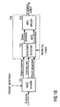
- Fig. 2 illustrates the operation of a spatial audio object (SAOC) encoder 101 taught by current invention.
- the N audio objects are fed both into a downmixer 201 and an audio object parameter extractor 202.
- the downmixer 201 mixes the objects into an object downmix consisting of K > 1 audio channels, according to the encoder parameters and also outputs downmix information.
- This information includes a description of the applied downmix weight matrix D and, optionally, if the subsequent audio object parameter extractor operates in prediction mode, parameters describing the power and correlation of the object downmix.
- the audio object parameter extractor 202 extracts object parameters according to the encoder parameters.
- the encoder control determines on a time and frequency varying basis which one of two encoder modes is applied, the energy based or the prediction based mode.
- the encoder parameters further contains information on a grouping of the N audio objects into P stereo objects and N-2P mono objects. Each mode will be further described by Figures 3 and 4 .
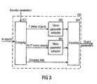
- Fig. 3 illustrates an audio object parameter extractor 202 operating in energy based mode.
- a grouping 301 into P stereo objects and N - 2 P mono objects is performed according to grouping information contained in the encoder parameters. For each considered time frequency interval the following operations are then performed.
- Two object powers and one normalized correlation are extracted for each of the P stereo objects by the stereo parameter extractor 302.
- One power parameter is extracted for each of the N - 2 P mono objects by the mono parameter extractor 303.
- the total set of N power parameters and P normalized correlation parameters is then encoded in 304 together with the grouping data to form the object parameters.
- the encoding can contain a normalization step with respect to the largest object power or with respect to the sum of extracted object powers.
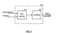
- Fig. 4 illustrates an audio object parameter extractor 202 operating in prediction based mode. For each considered time frequency interval the following operations are performed. For each of the N objects, a linear combination of the K object downmix channels is derived which matches the given object in a least squares sense. The K weights of this linear combination are called Object Prediction Coefficients (OPC) and they are computed by the OPC extractor 401. The total set of N • K OPC's are encoded in 402 to form the object parameters. The encoding can incorporate a reduction of total number of OPC's based on linear interdependencies. As taught by the present invention, this total number can be reduced to max ⁇ K •( N - K ),0 ⁇ if the downmix weight matrix D has full rank.
- OPC Object Prediction Coefficients
- Fig. 5 illustrates the structure of an SAOC to MPEG Surround transcoder 102 as taught by the current invention.
- the downmix side information and the object parameters are combined with the rendering matrix by the parameter calculator 502 to form MPEG Surround parameters of type CLD, CPC, and ICC, and a downmix converter matrix G of size 2 ⁇ K .
- the downmix converter 501 converts the object downmix into a stereo downmix by applying a matrix operation according to the G matrices.
- this matrix is the identity matrix and the object downmix is passed unaltered through as stereo downmix.
- This mode is illustrated in the drawing with the selector switch 503 in position A, whereas the normal operation mode has the switch in position B .
- An additional advantage of the transcoder is its usability as a stand alone application where the MPEG Surround parameters are ignored and the output of the downmix converter is used directly as a stereo rendering.
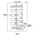
- Fig. 6 illustrates different operation modes of a downmix converter 501 as taught by the present invention.
- this bitstream is first decoded by the audio decoder 601 into K time domain audio signals. These signals are then all transformed to the frequency domain by an MPEG Surround hybrid QMF filter bank in the T/F unit 602.
- the time and frequency varying matrix operation defined by the converter matrix data is performed on the resulting hybrid QMF domain signals by the matrixing unit 603 which outputs a stereo signal in the hybrid QMF domain.
- the hybrid synthesis unit 604 converts the stereo hybrid QMF domain signal into a stereo QMF domain signal.
- the hybrid QMF domain is defined in order to obtain better frequency resolution towards lower frequencies by means of a subsequent filtering of the QMF subbands.
- this subsequent filtering is defined by banks of Nyquist filters
- the conversion from the hybrid to the standard QMF domain consists of simply summing groups of hybrid subband signals, see [ E. Schuijers, J. Breebart, and H. Purnhagen "Low complexity parametric stereo coding" Proc 116th AES convention Berlin ,Germany 2004 , Preprint 6073].
- This signal constitutes the first possible output format of the downmix converter as defined by the selector switch 607 in position A.
- Such a QMF domain signal can be fed directly into the corresponding QMF domain interface of an MPEG Surround decoder, and this is the most advantageous operation mode in terms of delay, complexity and quality.
- the next possibility is obtained by performing a QMF filter bank synthesis 605 in order to obtain a stereo time domain signal. With the selector switch 607 in position B the converter outputs a digital audio stereo signal that also can be fed into the time domain interface of a subsequent MPEG Surround decoder, or rendered directly in a stereo playback device.
- the third possibility with the selector switch 607 in position C is obtained by encoding the time domain stereo signal with a stereo audio encoder 606.
- the output format of the downmix converter is then a stereo audio bitstream which is compatible with a core decoder contained in the MPEG decoder.
- This third mode of operation is suitable for the case where the SAOC to MPEG Surround transcoder is separated by the MPEG decoder by a connection that imposes restrictions on bitrate, or in the case where the user desires to store a particular object rendering for future playback.
- Fig 7 illustrates the structure of an MPEG Surround decoder for a stereo downmix.
- the stereo downmix is converted to three intermediate channels by the Two-To-Three (TTT) box.
- TTT Two-To-Three
- OTT One-To-Two
- Fig. 8 illustrates a practical use case including an SAOC encoder.
- An audio mixer 802 outputs a stereo signal (L and R) which typically is composed by combining mixer input signals (here input channels 1-6) and optionally additional inputs from effect returns such as reverb etc.
- the mixer also outputs an individual channel (here channel 5) from the mixer. This could be done e.g. by means of commonly used mixer functionalities such as "direct outputs" or "auxiliary send” in order to output an individual channel post any insert processes (such as dynamic processing and EQ).
- the stereo signal (L and R) and the individual channel output (obj5) are input to the SAOC encoder 801, which is nothing but a special case of the SAOC encoder 101 in Fig. 1 .
- a signal block of L samples represents the signal in a time and frequency interval which is a part of the perceptually motivated tiling of the time-frequency plane which is applied for the description of signal properties.
- the downmix weight matrix D of size K ⁇ N where K > 1 determines the K channel downmix signal in the form of a matrix with K rows through the matrix multiplication X DS .
- the task of the SAOC decoder is to generate an approximation in the perceptual sense of the target rendering Y of the original audio objects, given the rendering matrix A ,the downmix X the downmix matrix D , and object parameters.
- the object parameters in the energy mode taught by the present invention carry information about the covariance of the original objects.
- this covariance is given in un-normalized form by the matrix product SS • where the star denotes the complex conjugate transpose matrix operation.
- energy mode object parameters furnish a positive semi-definite N ⁇ N matrix E such that, possibly up to a scale factor, S ⁇ S * ⁇ E .
- the ICC data can then be combined with the energies in order to form a matrix E with 2 P off diagonal entries.
- the transmitted energy and correlation data is S 1 , S 2 , S 3 and ⁇ 1.2 .
- the downmix left channel is 2 and the right channel is 2 .
- the OPC's for the single track aim at approximating s 3 ⁇ c 31 x 1 + c 32 x 2 and the equation (11) can in this case be solved to achieve 2 , 2 , 2 , and 2 .
- the transcoder has to output a stereo downmix ( l 0 , r 0 ) and parameters for the TTT and OTT boxes.
- K 2
- K 2
- both the object parameters and the MPS TTT parameters exist in both an energy mode and a prediction mode, all four combinations have to be considered.
- the energy mode is a suitable choice for instance in case the downmix audio coder is not of waveform coder in the considered frequency interval. It is understood that the MPEG Surround parameters derived in the following text have to be properly quantized and coded prior to their transmission.
- the object parameters can be in both energy or prediction mode, but the transcoder should preferably operate in prediction mode. If the downmix audio coder is not a waveform coder the in the considered frequency interval, the object encoder and the and the transcoder should both operate in energy mode.
- the fourth combination is of less relevance so the subsequent description will address the first three combinations only.
- the data available to the transcoder is described by the triplet of matrices ( D , E , A ).
- the MPEG Surround OTT parameters are obtained by performing energy and correlation estimates on a virtual rendering derived from the transmitted parameters and the 6 ⁇ N rendering matrix A .
- the MPEG surround decoder will be instructed to use some decorrelation between right front and right surround but no decorrelation between left front and left surround.
- the matrix C 3 contains the best weights for obtaining an approximation to the desired object rendering to the combined channels ( l,r,qc ) from the object downmix.
- This general type of matrix operation cannot be implemented by the MPEG surround decoder, which is tied to a limited space of TTT matrices through the use of only two parameters.
- the object of the inventive downmix converter is to pre-process the object downmix such that the combined effect of the pre-processing and the MPEG Surround TTT matrix is identical to the desired upmix described by C 3 .
- the available data is represented by the matrix triplet ( D , C , A ) where C is the N ⁇ 2 matrix holding the N pairs of OPC's. Due to the relative nature of prediction coefficients, it will further be necessary for the estimation of energy based MPEG Surround parameters to have access to an approximation to the 2 ⁇ 2 covariance matrix of the object downmix, X ⁇ X * ⁇ Z .
- This information is preferably transmitted from the object encoder as part of the downmix side information, but it could also be estimated at the transcoder from measurements performed on the received downmix, or indirectly derived from ( D , C ) by approximate object model considerations.
- OPC's arises in combination with MPEG Surround TIT parameters in prediction mode.
- the resulting matrix G is fed to the downmix converter and the TTT parameters ( ⁇ , ⁇ ) are transmitted to the MPEG Surround decoder.
- the object to stereo downmix converter 501 outputs an approximation to a stereo downmix of the 5.1 channel rendering of the audio objects.
- this downmix is interesting in its own right and a direct manipulation of the stereo rendering A 2 is attractive.
- the design of the downmix converter matrix is based on GDS ⁇ A 2 ⁇ S .
- Fig. 9 illustrates a preferred embodiment of an audio object coder in accordance with one aspect of the present invention.
- the audio object encoder 101 has already been generally described in connection with the preceding figures.
- the audio object coder for generating the encoded object signal uses the plurality of audio objects 90 which have been indicated in Fig. 9 as entering a downmixer 92 and an object parameter generator 94.
- the audio object encoder 101 includes the downmix information generator 96 for generating downmix information 97 indicating a distribution of the plurality of audio objects into at least two downmix channels indicated at 93 as leaving the downmixer 92.
- the object parameter generator is for generating object parameters 95 for the audio objects, wherein the object parameters are calculated such that the reconstruction of the audio object is possible using the object parameters and at least two downmix channels 93. Importantly, however, this reconstruction does not take place on the encoder side, but takes place on the decoder side. Nevertheless, the encoderside object parameter generator calculates the object parameters for the objects 95 so that this full reconstruction can be performed on the decoder side.
- the audio object encoder 101 includes an output interface 98 for generating the encoded audio object signal 99 using the downmix information 97 and the object parameters 95.
- the downmix channels 93 can also be used and encoded into the encoded audio object signal.
- the output interface 98 generates an encoded audio object signal 99 which does not include the downmix channels. This situation may arise when any downmix channels to be used on the decoder side are already at the decoder side, so that the downmix information and the object parameters for the audio objects are transmitted separately from the downmix channels.
- Such a situation is useful when the object downmix channels 93 can be purchased separately from the object parameters and the downmix information for a smaller amount of money, and the object parameters and the downmix information can be purchased for an additional amount of money in order to provide the user on the decoder side with an added value.
- the object parameters and the downmix information enable the user to form a flexible rendering of the audio objects at any intended audio reproduction setup, such as a stereo system, a multi-channel system or even a wave field synthesis system. While wave field synthesis systems are not yet very popular, multi-channel systems such as 5.1 systems or 7.1 systems are becoming increasingly popular on the consumer market.
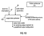
- Fig. 10 illustrates an audio synthesizer for generating output data.
- the audio synthesizer includes an output data synthesizer 100.
- the output data synthesizer receives, as an input, the downmix information 97 and audio object parameters 95 and, probably, intended audio source data such as a positioning of the audio sources or a user-specified volume of a specific source, which the source should have been when rendered as indicated at 101.
- the output data synthesizer 100 is for generating output data usable for creating a plurality of output channels of a predefined audio output configuration representing a plurality of audio objects. Particularly, the output data synthesizer 100 is operative to use the downmix information 97, and the audio object parameters 95. As discussed in connection with Fig. 11 later on, the output data can be data of a large variety of different useful applications, which include the specific rendering of output channels or which include just a reconstruction of the source signals or which include a transcoding of parameters into spatial rendering parameters for a spatial upmixer configuration without any specific rendering of output channels, but e.g. for storing or transmitting such spatial parameters.
- Fig. 14 The general application scenario of the present invention is summarized in Fig. 14 .
- an encoder side 140 which includes the audio object encoder 101 which receives, as an input, N audio objects.
- the output of the preferred audio object encoder comprises, in addition to the downmix information and the object parameters which are not shown in Fig. 14 , the K downmix channels.
- the number of downmix channels in accordance with the present invention is greater than or equal to two.
- the downmix channels are transmitted to a decoder side 142, which includes a spatial upmixer 143.
- the spatial upmixer 143 may include the inventive audio synthesizer, when the audio synthesizer is operated in a transcoder mode.
- the audio synthesizer 101 as illustrated in Fig. 10 works in a spatial upmixer mode, then the spatial upmixer 143 and the audio synthesizer are the same device in this embodiment.
- the spatial upmixer generates M output channels to be played via M speakers. These speakers are positioned at predefined spatial locations and together represent the predefined audio output configuration.
- An output channel of the predefined audio output configuration may be seen as a digital or analog speaker signal to be sent from an output of the spatial upmixer 143 to the input of a loudspeaker at a predefined position among the plurality of predefined positions of the predefined audio output configuration.
- the number of M output channels can be equal to two when stereo rendering is performed.
- the number of M output channels is larger than two.
- M is larger than K and may even be much larger than K, such as double the size or even more.
- Fig. 14 furthermore includes several matrix notations in order to illustrate the functionality of the inventive encoder side and the inventive decoder side.
- blocks of sampling values are processed. Therefore, as is indicated in equation (2), an audio object is represented as a line of L sampling values.
- the matrix S has N lines corresponding to the number of objects and L columns corresponding to the number of samples.
- the matrix E is calculated as indicated in equation (5) and has N columns and N lines.
- the matrix E includes the object parameters when the object parameters are given in the energy mode.
- the matrix E has, as indicated before in connection with equation (6) only main diagonal elements, wherein a main diagonal element gives the energy of an audio object. All off-diagonal elements represent, as indicated before, a correlation of two audio objects, which is specifically useful when some objects are two channels of the stereo signal.
- equation (2) is a time domain signal. Then a single energy value for the whole band of audio objects is generated.
- the audio objects are processed by a time/frequency converter which includes, for example, a type of a transform or a filter bank algorithm.
- equation (2) is valid for each subband so that one obtains a matrix E for each subband and, of course, each time frame.
- the downmix channel matrix X has K lines and L columns and is calculated as indicated in equation (3).
- the M output channels are calculated using the N objects by applying the so-called rendering matrix A to the N objects.
- the N objects can be regenerated on the decoder side using the downmix and the object parameters and the rendering can be applied to the reconstructed object signals directly.
- the downmix can be directly transformed to the output channels without an explicit calculation of the source signals.
- the rendering matrix A indicates the positioning of the individual sources with respect to the predefined audio output configuration. If one had six objects and six output channels, then one could place each object at each output channel and the rendering matrix would reflect this scheme. If, however, one would like to place all objects between two output speaker locations, then the rendering matrix A would look different and would reflect this different situation.
- the rendering matrix or, more generally stated, the intended positioning of the objects and also an intended relative volume of the audio sources can in general be calculated by an encoder and transmitted to the decoder as a so-called scene description.
- this scene description can be generated by the user herself/himself for generating the user-specific upmix for the user-specific audio output configuration.
- a transmission of the scene description is, therefore, not necessarily required, but the scene description can also be generated by the user in order to fulfill the wishes of the user.
- the user might, for example, like to place certain audio objects at places which are different from the places where these objects were when generating these objects.
- the audio objects are designed by themselves and do not have any "original" location with respect to the other objects. In this situation, the relative location of the audio sources is generated by the user at the first time.
- a downmixer 92 is illustrated.
- the downmixer is for downmixing the plurality of audio objects into the plurality of downmix channels, wherein the number of audio objects is larger than the number of downmix channels, and wherein the downmixer is coupled to the downmix information generator so that the distribution of the plurality of audio objects into the plurality of downmix channels is conducted as indicated in the downmix information.
- the downmix information generated by the downmix information generator 96 in Fig. 9 can be automatically created or manually adjusted. It is preferred to provide the downmix information with a resolution smaller than the resolution of the object parameters.
- the downmix information represents a downmix matrix having K lines and N columns.
- the value in a line of the downmix matrix has a certain value when the audio object corresponding to this value in the downmix matrix is in the downmix channel represented by the row of the downmix matrix.
- the values of more than one row of the downmix matrix have a certain value.
- Other values, however, are possible as well.
- audio objects can be input into one or more downmix channels with varying levels, and these levels can be indicated by weights in the downmix matrix which are different from one and which do not add up to 1.0 for a certain audio object.
- the encoded audio object signal may be for example a time-multiplex signal in a certain format.
- the encoded audio object signal can be any signal which allows the separation of the object parameters 95, the downmix information 97 and the downmix channels 93 on a decoder side.
- the output interface 98 can include encoders for the object parameters, the downmix information or the downmix channels. Encoders for the object parameters and the downmix information may be differential encoders and/or entropy encoders, and encoders for the downmix channels can be mono or stereo audio encoders such as MP3 encoders or AAC encoders. All these encoding operations result in a further data compression in order to further decrease the data rate required for the encoded audio object signal 99.
- the downmixer 92 is operative to include the stereo representation of background music into the at least two downmix channels and furthermore introduces the voice track into the at least two downmix channels in a predefined ratio.
- a first channel of the background music is within the first downmix channel and the second channel of the background music is within the second downmix channel. This results in an optimum replay of the stereo background music on a stereo rendering device. The user can, however, still modify the position of the voice track between the left stereo speaker and the right stereo speaker.
- the first and the second background music channels can be included in one downmix channel and the voice track can be included in the other downmix channel.
- a downmixer 92 is adapted to perform a sample by sample addition in the time domain. This addition uses samples from audio objects to be downmixed into a single downmix channel. When an audio object is to be introduced into a downmix channel with a certain percentage, a pre-weighting is to take place before the sample-wise summing process. Alternatively, the summing can also take place in the frequency domain, or a subband domain, i.e., in a domain subsequent to the time/frequency conversion. Thus, one could even perform the downmix in the filter bank domain when the time/frequency conversion is a filter bank or in the transform domain when the time/frequency conversion is a type of FFT, MDCT or any other transform.
- the object parameter generator 94 generates energy parameters and, additionally, correlation parameters between two objects when two audio objects together represent the stereo signal as becomes clear by the subsequent equation (6).
- the object parameters are prediction mode parameters.
- Fig. 15 illustrates algorithm steps or means of a calculating device for calculating these audio object prediction parameters. As has been discussed in connection with equations (7) to (12), some statistical information on the downmix channels in the matrix X and the audio objects in the matrix S has to be calculated. Particularly, block 150 illustrates the first step of calculating the real part of S ⁇ X* and the real part of X ⁇ X*.
- Fig. 7 illustrates several kinds of output data usable for creating a plurality of output channels of a predefined audio output configuration.
- Line 111 illustrates a situation in which the output data of the output data synthesizer 100 are reconstructed audio sources.
- the input data required by the output data synthesizer 100 for rendering the reconstructed audio sources include downmix information, the downmix channels and the audio object parameters.
- an output configuration and an intended positioning of the audio sources themselves in the spatial audio output configuration are not necessarily required.
- the output data synthesizer 100 would output reconstructed audio sources.
- the output data synthesizer 100 works as defined by equation (7).
- the output data synthesizer uses an inverse of the downmix matrix and the energy matrix for reconstructing the source signals.
- the output data synthesizer 100 operates as a transcoder as illustrated for example in block 102 in Fig. 1b .
- the output synthesizer is a type of a transcoder for generating spatial mixer parameters
- the downmix information, the audio object parameters, the output configuration and the intended positioning of the sources are required.
- the output configuration and the intended positioning are provided via the rendering matrix A.
- the downmix channels are not required for generating the spatial mixer parameters as will be discussed in more detail in connection with Fig. 12 .
- the spatial mixer parameters generated by the output data synthesizer 100 can then be used by a straight-forward spatial mixer such as an MPEG-surround mixer for upmixing the downmix channels.
- This embodiment does not necessarily need to modify the object downmix channels, but may provide a simple conversion matrix only having diagonal elements as discussed in equation (13).
- the output data synthesizer 100 would, therefore, output spatial mixer parameters and, preferably, the conversion matrix G as indicated in equation (13), which includes gains that can be used as arbitrary downmnix gain parameters (ADG) of the MPEG-surround decoder.
- ADG downmnix gain parameters
- the output data include spatial mixer parameters at a conversion matrix such as the conversion matrix illustrated in connection with equation (25).
- the output data synthesizer 100 does not necessarily have to perform the actual downmix conversion to convert the object downmix into a stereo downmix.
- a different mode of operation indicated by mode number 4 in line 114 in Fig. 11 illustrates the output data synthesizer 100 of Fig. 10 .
- the transcoder is operated as indicated by 102 in Fig. 1b and outputs not only spatial mixer parameters but additionally outputs a converted downmix. However, it is not necessary anymore to output the conversion matrix G in addition to the converted downmix. Outputting the converted downmix and the spatial mixer parameters is sufficient as indicated by Fig. 1b .
- Mode number 5 indicates another usage of the output data synthesizer 100 illustrated in Fig. 10 .
- the output data generated by the output data synthesizer do not include any spatial mixer parameters but only include a conversion matrix G as indicated by equation (35) for example or actually includes the output of the stereo signals themselves as indicated at 115.
- a stereo rendering is of interest and any spatial mixer parameters are not required.
- all available input information as indicated in Fig. 11 is required.
- Another output data synthesizer mode is indicated by mode number 6 at line 116.
- the output data synthesizer 100 generates a multi-channel output, and the output data synthesizer 100 would be similar to element 104 in Fig. 1b .
- the output data synthesizer 100 requires all available input information and outputs a multi-channel output signal having more than two output channels to be rendered by a corresponding number of speakers to be positioned at intended speaker positions in accordance with the predefined audio output configuration.
- Such a multi-channel output is a 5.1 output, a 7.1 output or only a 3.0 output having a left speaker, a center speaker and a right speaker.
- Fig. 11 illustrates one example for calculating several parameters from the Fig. 7 parameterization concept known from the MPEG-surround decoder.
- Fig. 7 illustrates an MPEG-surround decoder-side parameterization starting from the stereo downmix 70 having a left downmix channel l 0 and a right downmix channel r 0 .
- both downmix channels are input into a so-called Two-To-Three box 71.
- the Two-To-Three box is controlled by several input parameters 72.
- Box 71 generates three output channels 73a, 73b, 73c. Each output channel is input into a One-To-Two box.
- the intermediate signals indicated by 73a, 73b and 73c are not explicitly calculated by a certain embodiment, but are illustrated in Fig. 7 only for illustration purposes.
- boxes 74a, 74b receive some residual signals res l OTT , res 2 OTT which can be used for introducing a certain randomness into the output signals.
- box 71 is controlled either by prediction parameters CPC or energy parameters CLD TTT .
- prediction parameters CPC For the upmix from two channels to three channels, at least two prediction parameters CPC1, CPC2 or at least two energy parameters CLD 1 TTT and CLD 2 TTT are required.
- the correlation measure ICC TTT can be put into the box 71 which is, however, only an optional feature which is not used in one embodiment of the invention.
- Figs. 12 and 13 illustrate the necessary steps and/or means for calculating all parameters CPC/CLD TTT , CLD0, CLD1, ICCl, CLD2, ICC2 from the object parameters 95 of Fig. 9 , the downmix information 97 of Fig. 9 and the intended positioning of the audio sources, e.g. the scene description 101 as illustrated in Fig. 10 .
- These parameters are for the predefined audio output format of a 5.1 surround system.
- a rendering matrix A is provided.
- the rendering matrix indicates where the source of the plurality of sources is to be placed in the context of the predefined output configuration.
- Step 121 illustrates the derivation of the partial downmix matrix D 36 as indicated in equation (20). This matrix reflects the situation of a downmix from six output channels to three channels and has a size of 3xN. When one intends to generate more output channels than the 5.1 configuration, such as an 8-channel output configuration (7.1), then the matrix determined in block 121 would be a D 38 matrix.
- a reduced rendering matrix A 3 is generated by multiplying matrix D 36 and the full rendering matrix as defined in step 120.
- the downmix matrix D is introduced. This downmix matrix D can be retrieved from the encoded audio object signal when the matrix is fully included in this signal. Alternatively, the downmix matrix could be parameterized e.g. for the specific downmix information example and the downmix matrix G.
- the object energy matrix is provided in step 124.
- This object energy matrix is reflected by the object parameters for the N objects and can be extracted from the imported audio objects or reconstructed using a certain reconstruction rule.
- This reconstruction rule may include an entropy decoding etc.
- step 125 the "reduced" prediction matrix C 3 is defined.
- the values of this matrix can be calculated by solving the system of linear equations as indicated in step 125. Specifically, the elements of matrix C 3 can be calculated by multiplying the equation on both sides by an inverse of (DED*).
- step 126 the conversion matrix G is calculated.
- the conversion matrix G has a size of KxK and is generated as defined by equation (25).
- the specific matrix D TTT is to be provided as indicated by step 127.
- An example for this matrix is given in equation (24) and the definition can be derived from the corresponding equation for C TTT as defined in equation (22). Equation (22), therefore, defines what is to be done in step 128.
- Step 129 defines the equations for calculating matrix C TTT .
- the parameters ⁇ , ⁇ and ⁇ which are the CPC parameters, can be output.
- ⁇ is set to 1 so that the only remaining CPC parameters input into block 71 are ⁇ and ⁇ .
- the rendering matrix A is provided.
- the size of the rendering matrix A is N lines for the number of audio objects and M columns for the number of output channels.
- This rendering matrix includes the information from the scene vector, when a scene vector is used.
- the rendering matrix includes the information of placing an audio source in a certain position in an output setup.
- the rendering matrix is generated on the decoder side without any information from the encoder side. This allows a user to place the audio objects wherever the user likes without paying attention to a spatial relation of the audio objects in the encoder setup.
- the relative or absolute location of audio sources can be encoded on the encoder side and transmitted to the decoder as a kind of a scene vector. Then, on the decoder side, this information on locations of audio sources which is preferably independent of an intended audio rendering setup is processed to result in a rendering matrix which reflects the locations of the audio sources customized to the specific audio output configuration.
- step 131 the object energy matrix E which has already been discussed in connection with step 124 of Fig. 12 is provided.
- This matrix has the size of NxN and includes the audio object parameters.
- such an object energy matrix is provided for each subband and each block of time-domain samples or subband-domain samples.
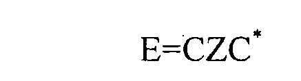
- the output energy matrix F is calculated.
- F is the covariance matrix of the output channels. Since the output channels are, however, still unknown, the output energy matrix F is calculated using the rendering matrix and the energy matrix.
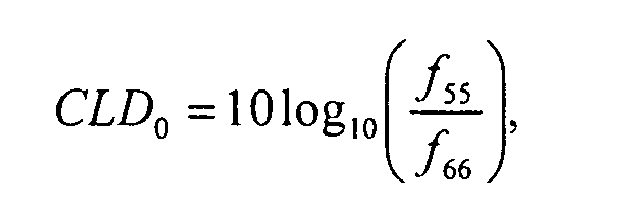
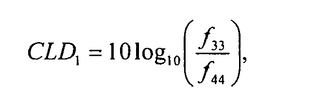
- These matrices are provided in steps 130 and 131 and are readily available on the decoder side. Then, the specific equations (15), (16), (17), (18) and (19) are applied to calculate the channel level difference parameters CLD 0 , CLD 1 , CLD 2 and the inter-channel coherence parameters ICC 1 and ICC 2 so that the parameters for the boxes 74a, 74b, 74c are available. Importantly, the spatial parameters are calculated by combining the specific elements of the output energy matrix F.
- step 133 all parameters for a spatial upmixer, such as the spatial upmixer as schematically illustrated in Fig. 7 , are available,
- the object parameters were given as energy parameters.
- the object parameters are given as prediction parameters, i.e. as an object prediction matrix C as indicated by item 124a in Fig. 12
- the calculation of the reduced prediction matrix C 3 is just a matrix multiplication as illustrated in block 125a and discussed in connection with equation (32).
- the matrix A 3 as used in block 125a is the same matrix A 3 as mentioned in block 122 of Fig. 12 .
- the object prediction matrix C is generated by an audio object encoder and transmitted to the decoder, then some additional calculations are required for generating the parameters for the boxes 74a, 74b, 74c. These additional steps are indicated in Fig. 13b .
- the object prediction matrix C is provided as indicated by 124a in Fig. 13b , which is the same as discussed in connection with block 124a of Fig. 12 .
- the covariance matrix of the object downmix Z is calculated using the transmitted downmix or is generated and transmitted as additional side information.
- the decoder does not necessarily have to perform any energy calculations which inherently introduce some delayed processing and increase the processing load on the decoder side.
- step 134 the object energy matrix E can be calculated as indicated by step 135 by using the prediction matrix C and the downmix covariance or "downmix energy" matrix Z.
- step 135 all steps discussed in connection with Fig. 13a can be performed, such as steps 132, 133, to generate all parameters for blocks 74a, 74b, 74c of Fig. 7 .
- Fig. 16 illustrates a further embodiment, in which only a stereo rendering is required.
- the stereo rendering is the output as provided by mode number 5 or line 115 of Fig. 11 .
- the output data synthesizer 100 of Fig. 10 is not interested in any spatial upmix parameters but is mainly interested in a specific conversion matrix G for converting the object downmix into a useful and, of course, readily influencable and readily controllable stereo downmix.
- an M-to-2 partial downmix matrix is calculated.
- the partial downmix matrix would be a downmix matrix from six to two channels, but other downmix matrices are available as well.
- the calculation of this partial downmix matrix can be, for example, derived from the partial downmix matrix D 36 as generated in step 121 and matrix D TTT as used in step 127 of Fig. 12 .
- a stereo rendering matrix A 2 is generated using the result of step 160 and the "big" rendering matrix A is illustrated in step 161.
- the rendering matrix A is the same matrix as has been discussed in connection with block 120 in Fig. 12 .
- the stereo rendering matrix may be parameterized by placement parameters ⁇ and ⁇ .
- ⁇ is set to 1 and ⁇ is set to 1 as well, then the equation (33) is obtained, which allows a variation of the voice volume in the example described in connection with equation (33).
- other parameters such as ⁇ and ⁇ are used, then the placement of the sources can be varied as well.
- the conversion matrix G is calculated by using equation (33).
- the matrix (DED*) can be calculated, inverted and the inverted matrix can be multiplied to the right-hand side of the equation in block 163.
- the conversion matrix G is there, and the object downmix X can be converted by multiplying the conversion matrix and the object downmix as indicated in block 164.
- the converted downmix X' can be stereo-rendered using two stereo speakers.
- certain values for ⁇ , ⁇ and ⁇ can be set for calculating the conversion matrix G.
- the conversion matrix G can be calculated using all these three parameters as variables so that the parameters can be set subsequent to step 163 as required by the user.
- Preferred embodiments solve the problem of transmitting a number of individual audio objects (using a multi-channel downmix and additional control data describing the objects) and rendering the objects to a given reproduction system (loudspeaker configuration).
- a technique on how to modify the object related control data into control data that is compatible to the reproduction system is introduced. It further proposes suitable encoding methods based on the MPEG Surround coding scheme.
- the inventive methods and signals can be implemented in hardware or in software.
- the implementation can be performed using a digital storage medium, in particular a disk or a CD having electronically readable control signals stored thereon, which can cooperate with a programmable computer system such that the inventive methods are performed.
- the present invention is, therefore, a computer program product with a program code stored on a machine-readable carrier, the program code being configured for performing at least one of the inventive methods, when the computer program products runs on a computer.
- the inventive methods are, therefore, a computer program having a program code for performing the inventive methods, when the computer program runs on a computer.
Landscapes
- Engineering & Computer Science (AREA)
- Physics & Mathematics (AREA)
- Acoustics & Sound (AREA)
- Signal Processing (AREA)
- Multimedia (AREA)
- Computational Linguistics (AREA)
- Health & Medical Sciences (AREA)
- Audiology, Speech & Language Pathology (AREA)
- Human Computer Interaction (AREA)
- Mathematical Physics (AREA)
- Mathematical Analysis (AREA)
- General Physics & Mathematics (AREA)
- Algebra (AREA)
- Mathematical Optimization (AREA)
- Pure & Applied Mathematics (AREA)
- Theoretical Computer Science (AREA)
- Stereophonic System (AREA)
- Compression, Expansion, Code Conversion, And Decoders (AREA)
- Medicines Containing Antibodies Or Antigens For Use As Internal Diagnostic Agents (AREA)
- Electron Tubes For Measurement (AREA)
- Investigating Or Analysing Biological Materials (AREA)
- Reduction Or Emphasis Of Bandwidth Of Signals (AREA)
- Signal Processing For Digital Recording And Reproducing (AREA)
- Telephone Function (AREA)
- Sorting Of Articles (AREA)
- Optical Measuring Cells (AREA)
Claims (50)
- Audioobjektcodierer (101) zum Erzeugen eines codierten Audioobjektsignals (99) unter Verwendung einer Mehrzahl von Audioobjekten (90), wobei die Mehrzahl von Audioobjekten ein Stereoobjekt umfasst, das durch zwei Audioobjekte dargestellt wird, die eine gewisse Nicht-Null-Korrelation aufweisen, mit folgenden Merkmalen:einen Abwärtsmischinformationsgenerator (96) zum Erzeugen von Abwärtsmischinformationen (97), die eine Verteilung der Mehrzahl von Audioobjekten auf zumindest zwei Abwärtsmischkanäle angeben;einen Objektparametergenerator (94) zum Erzeugen von Objektparametern für die Audioobjekte (95), wobei die Objektparameter Annäherungen von Objektenergien der Mehrzahl von Audioobjekten und Korrelationsdaten für das Stereoobjekt umfassen; undeine Ausgabeschnittstelle (98) zum Erzeugen des codierten Audioobjektsignals (99) unter Verwendung der Abwärtsmischinformationen und der Objektparameter.
- Der Audioobjektcodierer gemäß Anspruch 1, der ferner folgendes Merkmal umfasst:einen Abwärtsmischer (92) zum Abwärtsmischen der Mehrzahl von Audioobjekten zu der Mehrzahl von Abwärtsmischkanälen, wobei die Anzahl von Audioobjekten größer ist als die Anzahl von Abwärtsmischkanälen, und wobei der Abwärtsmischer mit dem Abwärtsmischinformationsgenerator gekoppelt ist, so dass die Verteilung der Mehrzahl von Audioobjekten auf die Mehrzahl von Abwärtsmischkanälen so durchgerührt wird, wie dies in den Abwärtsmischinformationen angegeben ist.
- Der Audioobjektcodierer gemäß Anspruch 2, bei dem die Ausgabeschnittstelle (98) dahin gehend wirksam ist, das codierte Audiosignal anhand einer zusätzlichen Verwendung der Mehrzahl von Abwärtsmischkanälen zu erzeugen.
- Der Audioobjektcodierer gemäß Anspruch 1, bei dem der Objektparamatergenerator (94) dahin gehend wirksam ist, die Objektparameter mit einer ersten Zeit- und Frequenzauflösung zu erzeugen, und bei dem der Abwärtsmischinformationsgenerator (96) dahin gehend wirksam ist, die Abwärtsmischinformationen mit einer zweiten Zeit- und Frequenzauflösung zu erzeugen, wobei die zweite Zeit- und Frequenzauflösung geringer ist als die erste Zeit- und Frequenzauflösung.
- Der Audioobjektcodierer gemäß Anspruch 1, bei dem der Abwärtsmischinformationsgenerator (96) dahin gehend wirksam ist, die Abwärtsmischinformationen derart zu erzeugen, dass die Abwärtsmischinformationen für das gesamte Frequenzband der Audioobjekte gleich sind.
- Der Audioobjektcodierer gemäß Anspruch 1, bei dem der Abwärtsmischinformationsgenerator (96) dahin gehend wirksam ist, die Abwärtsmischinformationen derart zu erzeugen, dass die Abwärtsmischinformationen eine Abwärtsmischmatrix darstellen, die wie folgt definiert ist:
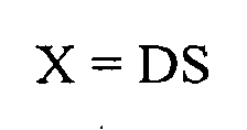
wobei S die Matrix ist und die Audioobjekte darstellt und eine Anzahl von Zeilen aufweist, die gleich der Anzahl von Audioobjekten ist,
wobei D die Abwärtsmischmatrix ist, und
wobei X eine Matrix ist und die Mehrzahl von Abwärtsmischkanälen darstellt und eine Anzahl von Zeilen aufweist, die gleich der Anzahl von Abwärtsmischkanälen ist. - Der Audioobjektcodierer gemäß Anspruch 1, bei dem der Abwärtsmischinformationsgenerator (96) dahin gehend wirksam ist, die Abwärtsmischinformationen zu berechnen, so dass die Abwärtsmischinformationen
angeben welches Audioobjekt in einem oder mehreren der Mehrzahl von Abwärtsmischkanälen vollständig oder teilweise aufgenommen ist, und
wenn ein Audioobjekt in mehr als einem Abwärtsmischkanal aufgenommen ist, Informationen über einen Teil des in einem Abwärtsmischkanal der mehr als ein Abwärtsmischkanäle aufgenommenen Audioobjekts angeben. - Der Audioobjektcodierer gemäß Anspruch 7, bei dem die Informationen über einen Teil ein Faktor sind, der kleiner ist als 1 und größer ist als 0.
- Der Audioobjektcodierer gemäß Anspruch 2, bei dem der Abwärtsmischer (92) dahin gehend wirksam ist, die Stereodarstellung von Hintergrundmusik in die zumindest zwei Abwärtsmischkanäle aufzunehmen und eine Sprachspur in einem vordefinierten Verhältnis in die zumindest zwei Abwärtsmischkanäle einzubringen.
- Der Audioobjektcodierer gemäß Anspruch 2, bei dem der Abwärtsmischer (92) dahin gehend wirksam ist, eine Abtastwert um Abtastwert erfolgende Hinzufügung von Signalen durchzuführen, die in einen Abwärtsmischkanal einzugeben sind, wie durch die Abwärtsmischinformationen angegeben ist.
- Der Audioobjektcodierer gemäß Anspruch 1, bei dem die Ausgabeschnittstelle (98) dahin gehend wirksam ist, vor dem Erzeugen des codierten Audioobjektsignals eine Datenkomprimierung der Abwärtsmischinformationen und der Objektparameter durchzuführen.
- Der Audioobjektcodierer gemäß Anspruch 1, bei dem der Abwärtsmischinformationsgenerator (96) dahin gehend wirksam ist, Leistungsinformationen und Korrelationsinformationen zu erzeugen, die eine Leistungscharakteristik und eine Korrelationscharakteristik der zumindest zwei Abwärtsmischkanäle angeben.
- Der Audioobjektcodierer gemäß Anspruch 1, bei dem der Abwärtsmischinformationsgenerator Gruppierungsinformationen erzeugt, die die zwei Audioobjekte angeben, die das Stereoobjekt bilden.
- Der Audioobjektcodierer gemäß Anspruch 1, bei dem der Objektparametergenerator (94) dahin gehend wirksam ist, Objektvorhersageparameter für die Audioobjekte zu erzeugen, wobei die Vorhersageparameter derart berechnet sind, dass die gewichtete Hinzufügung der Abwärtsmischkanäle für ein durch die Vorhersageparameter oder das Quellenobjekt gesteuertes Quellenobjekt zu einer Annäherung des Quellenobjekts führt.
- Der Audioobjektcodierer gemäß Anspruch 14, bei dem die Vorhersageparameter pro Frequenzband erzeugt werden und bei dem die Audioobjekte eine Mehrzahl von Frequenzbändern abdecken.
- Der Audioobjektcodierer gemäß Anspruch 14, bei dem die Anzahl von Audioobjekten gleich N ist, die Anzahl von Abwärtsmischkanälen gleich K ist und die Anzahl von durch den Objektparametergenerator (94) berechneten Objektvorhersageparametern gleich oder kleiner ist als N · K.
- Der Audioobjektcodierer gemäß Anspruch 16, bei dem der Objektparametergenerator (94) dahin gehend wirksam ist, höchstens K · (N-K) Objektvorhersageparameter zu berechnen.
- Audioobjektcodierungsverfahren zum Erzeugen eines codierten Audioobjekt(99)-Signals unter Verwendung einer Mehrzahl von Audioobjekten (90), wobei die Mehrzahl von Audioobjekten ein Stereoobjekt umfasst, das durch zwei Audioobjekte dargestellt wird, die eine gewisse Nicht-Null-Korrelation aufweisen, mit folgenden Schritten:Erzeugen (96) von Abwärtsmischinformationen (97), die eine Verteilung der Mehrzahl von Audioobjekten auf zumindest zwei Abwärtsmischkanäle angeben;Erzeugen (94) von Objektparametern für die Audioobjekte (95), wobei die Objektparameter Annäherungen von Objektenergien der Mehrzahl von Audioobjekten und Korrelationsdaten für das Stereoobjekt umfassen; undErzeugen (98) des codierten Audioobjektsignals (99) unter Verwendung der Abwärtsmischinformationen und der Objektparameter.
- Audiosynthetisierer (101) zum Erzeugen von Ausgangsdaten unter Verwendung eines codierten Audioobjektsignals, wobei das codierte Audioobjektsignal Objektparameter (95) für eine Mehrzahl von Audioobjekten und Abwärtsmischinformationen (97) umfasst, mit folgendem Merkmal:einem Ausgangsdatensynthetisierer (100) zum Erzeugen der Ausgangsdaten, die zum Aufbereiten einer Mehrzahl von Ausgangskanälen einer vordefinierten Audioausgangskonfiguration verwendbar sind, die die Mehrzahl von Audioobjekten darstellt, wobei die Mehrzahl von Audioobjekten ein Stereoobjekt umfasst, das durch zwei Audioobjekte dargestellt wird, die eine gewisse Nicht-Null-Korrelation aufweisen, wobei der Ausgangsdatensynthetisierer dahin gehend wirksam ist, als als Eingabe die Objektparameter (95) zu empfangen, wobei die Objektparameter (95) Annäherungen von Objektenergien der Mehrzahl von Audioobjekten und Korrelationsdaten für das Stereoobjekt umfassen, und die Abwärtsmischinformationen (97), die eine Verteilung der Mehrzahl von Audioobjekten auf zumindest zwei Abwärtsmischkanäle angeben, und die Objektparameter (95) für die Audioobjekte zu verwenden.
- Der Audiosynthetisierer gemäß Anspruch 19, bei dem der Ausgangsdatensynthetisierer (100) dahin gehend wirksam ist, unter zusätzlicher Verwendung einer beabsichtigten Positionierung der Audioobjekte in der Audioausgangskonfiguration die Objektparameter in räumliche Parameter für die vordefinierte Audioausgangskonfiguration umzucodieren.
- Der Audiosynthetisierer gemäß Anspruch 19, bei dem der Ausgangsdatensynthetisierer (100) dahin gehend wirksam ist, unter Verwendung einer von der beabsichtigten Positionierung der Audioobjekte abgeleiteten Umwandlungsmatrix eine Mehrzahl von Abwärtsmischkanälen in die Stereoabwärtsmischung für die vordefinierte Audioausgangskonfiguration umzuwandeln.
- Der Audiosynthetisierer gemäß Anspruch 21, bei dem der Ausgangsdatensynthetisierer (100) dahin gehend wirksam ist, die Umwandlungsmatrix unter Verwendung der Abwärtsmischinformationen zu bestimmen, wobei die Umwandlungsmatrix so berechnet wird, dass zumindest Teile der Abwärtsmischkanäle vertauscht werden, wenn ein Audioobjekt, das in einem ersten Abwärtsmischkanal enthalten ist, der die erste Hälfte einer Stereoebene darstellt, in der zweiten Hälfte der Stereoebene abgespielt werden soll.
- Der Audiosynthetisierer gemäß Anspruch 20, der ferner einen Kanalaufbereiter (104) zum Aufbereiten von Audioausgangskanälen für die vordefinierte Audioausgangskonfiguration unter Verwendung der räumlichen Parameter und der zumindest zwei Abwärtsmischkanäle oder der umgewandelten Abwärtsmischkanäle umfasst.
- Der Audiosynthetisierer gemäß Anspruch 19, bei dem der Ausgangsdatensynthetisierer (100) dahin gehend wirksam ist, unter zusätzlicher Verwendung der zumindest zwei Abwärtsmischkanäle die Ausgangskanäle der vordefinierten Audioausgangskonfiguration auszugeben.
- Der Audiosynthetisierer gemäß Anspruch 19, bei dem die räumlichen Parameter die erste Gruppe von Parametern für eine Zwei-Zu-Drei-Aufwärtsmischung und eine zweite Gruppe von Energieparametern für eine Drei-Zwei-Sechs-Aufwärtsmischung umfassen, und
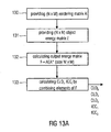
bei dem der Ausgangsdatensynthetisierer (100) dahin gehend wirksam ist, die Vorhersageparameter für die Zwei-Zu-Drei-Vorhersagematrix unter Verwendung der Aufbereitungsmatrix, wie sie durch eine beabsichtigte Positionierung der Audioobjekte bestimmt wird, einer Teilabwärtsmischmatrix, die das Abwärtsmischen der Ausgangskanäle zu drei Kanälen, die durch einen hypothetischen Zwei-Zu-Drei-Aufwärtsmischprozess erzeugt werden, beschreibt, und der Abwärtsmischmatrix zu berechnen. - Der Audiosynthetisierer gemäß Anspruch 25, bei dem der Ausgangsdatensynthetisierer (100) dahin gehend wirksam ist, tatsächliche Abwärtsmischgewichte für die Teilabwärtsmischmatrix derart zu berechnen, dass eine Energie einer gewichteten Summe zweier Kanäle gleich den Energien der Kanäle innerhalb eines Begrenzungsfaktors ist.
- Der Audiosynthetisierer gemäß Anspruch 26, bei dem die Abwärtsmischgewichte für die Teilabwärtsmischmatrix wie folgt ermittelt werden:

wobei wp ein Abwärtsmischgewicht ist, p eine ganzzahlige Indexvariable ist, fj,i ein Matrixelement einer Energiematrix ist, die eine Annäherung einer Kovarianzmatrix der Ausgangskanäle der vordefinierten Ausgangskonfiguration darstellt. - Der Audiosynthetisierer gemäß Anspruch 25, bei dem der Ausgangsdatensynthetisierer (100) dahin gehend wirksam ist, getrennte Koeffizienten der Vorhersagematrix durch Lösen eines Systems linearer Gleichungen zu berechnen.
- Der Audiosynthetisierer gemäß Anspruch 25, bei dem der Ausgangsdatensynthetisierer (100) dahin gehend wirksam ist, das System linearer Gleichungen auf der Basis von:

zu lösen, wobei C3 Zwei-Zu-Drei-Vorhersagematrix ist, D die von den Abwärtsmischinformationen abgeleitete Abwärtsmischmatrix ist, E eine von den Audioquellenobjekten abgeleitete Energiematrix ist und A3 die reduzierte Abwärtsmischmatrix ist, und wobei das "*" die komplex konjugierte Operation angibt. - Der Audiosynthetisierer gemäß Anspruch 25, bei dem die Vorhersageparameter für die Zwei-Zu-Drei-Aufwärtsmischung von einer Parametrisierung der Vorhersagematrix abgeleitet sind, so dass die Vorhersagematrix durch Verwendung lediglich zweier Parameter definiert ist, und
bei dem der Ausgangsdatensynthetisierer (100) dahin gehend wirksam ist, die zumindest zwei Abwärtsmischkanäle vorzubearbeiten, so dass die Wirkung des Vorbearbeitens und der parametrisierten Vorhersagematrix einer gewünschten Aufwärtsmischmatrix entspricht. - Der Audiosynthetisierer gemäß Anspruch 30, bei dem die Parametrisierung der Vorhersagematrix wie folgt ist:

wobei der Index TTT die parametrisierte Vorhersagematrix ist und wobei α, β und γ Faktoren sind. - Der Audiosynthetisierer gemäß Anspruch 19, bei dem eine Abwärtsmischumwandlungsmatrix G wie folgt berechnet wird:
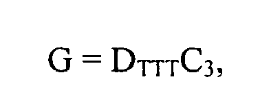
wobei C3 eine Zwei-Zu-Drei-Vorhersagematrix ist, wobei DTTT und CTTT gleich I sind, wobei I eine Zwei-Mal-Zwei-Identitätsmatrix ist, und wobei CTTT auf:
beruht, wobei α, β und γ konstante Faktoren sind. - Der Audiosynthetisierer gemäß Anspruch 32, bei dem die Vorhersageparameter für die Zwei-Zu-Drei-Aufwärtsmischung als α und β bestimmt sind, wobei γ auf 1 festgelegt ist.
- Der Audiosynthetisierer gemäß Anspruch 25, bei dem der Ausgangsdatensynthetisierer (100) dahin gehend wirksam ist, die Energieparameter für die Drei-Zwei-Sechs-Aufwärtsmischung unter Verwendung einer Energiematrix F auf der Basis von:

zu berechnen, wobei A die Aufbereitungsmatrix ist, E die von den Audioquellenobjekten abgeleitete Energiematrix ist, Y eine Ausgangskanalmatrix ist und "*" die komplex konjugierte Operation angibt. - Der Audiosynthetisierer gemäß Anspruch 34, bei dem der Ausgangsdatensynthetisierer (100) dahin gehend wirksam ist, die Energieparameter durch Kombinieren von Elementen der Energiematrix zu berechnen.
- Der Audiosynthetisierer gemäß Anspruch 35, bei dem der Ausgangsdatensynthetisierer (100) dahin gehend wirksam ist, die Energieparameter auf der Basis der folgenden Gleichungen zu berechnen:


wobei ϕ ein Absolutwert- ϕ(z)=|z| oder ein Echtwert-Operator ϕ(z)=Re{z} ist,
wobei CLD0 ein Erstkanalpegeldifferenzenergieparameter ist, wobei CLD1 ein Zweitkanalpegeldifferenzenergieparameter ist, wobei CLD2 ein Drittkanalpegeldifferenzenergieparameter ist, wobei ICC1 ein erster Zwischenkanalkohärenzenergieparameter ist und ICC2 ein zweiter Zwischenkanalkohärenzenergieparameter ist und wobei fij Elemente einer Energiematrix F an Positionen i,j in dieser Matrix sind. - Der Audiosynthetisierer gemäß Anspruch 25, bei dem die erste Gruppe von Parametern Energieparameter umfasst und bei dem der Ausgangsdatensynthetisierer (100) dahin gehend wirksam ist, die Energieparameter durch Kombinieren von Elementen der Energiematrix F abzuleiten.
- Der Audiosynthetisierer gemäß Anspruch 37, bei dem die Energieparameter auf der Basis von:


abgeleitet sind, wobei CLD0 TTT ein erster Energieparameter der ersten Gruppe ist und wobei CLD1 TTT ein zweiter Energieparameter der ersten Gruppe von Parametern ist. - Der Audiosynthetisierer gemäß Anspruch 37 oder 38, bei dem der Ausgangsdatensynthetisierer (100) dahin gehend wirksam ist, Gewichtsfaktoren zum Gewichten der Abwärtsmischkanäle zu berechnen, wobei die Gewichtsfaktoren zum Steuern von willkürlichen Abwärtsmischgewinnfaktoren des räumlichen Decodierers verwendet werden.
- Der Audiosynthetisierer gemäß Anspruch 39, bei dem der Ausgangsdatensynthetisierer dahin gehend wirksam ist, die Gewichtsfaktoren auf der Basis von:


zu berechnen, wobei D die Abwärtsmischmatrix ist, E eine von den Audioquellenobjekten abgeleitete Energiematrix ist, wobei W eine Zwischenmatrix ist, wobei D26 die Teilabwärtsmischmatrix zum Abwärtsmischen von 6 zu 2 Kanälen der vorbestimmten Ausgangskonfiguration ist und wobei G die Umwandlungsmatrix ist, die die willkürlichen Abwärtsmischgewinnfaktoren des räumlichen Decodierers umfasst. - Der Audiosynthetisierer gemäß Anspruch 25, bei dem die Objektparameter Objektvorhersageparameter sind und bei dem der Ausgangsdatensynthetisierer dahin gehend wirksam ist, eine Energiematrix auf der Basis der Objektvorhersageparameter, der Abwärtsmischinformationen und der den Abwärtsmischkanälen entsprechenden Energieinformationen vorab zu berechnen.
- Der Audiosynthetisierer gemäß Anspruch 41, bei dem der Ausgangsdatensynthetisierer (100) dahin gehend wirksam ist, die Energiematrix auf der Basis von:
zu berechnen, wobei E die Energiematrix ist, C die Vorhersageparametermatrix ist und Z eine Kovarianzmatrix der zumindest zwei Abwärtsmischkanäle ist. - Der Audiosynthetisierer gemäß Anspruch 19, bei dem der Ausgangsdatensynthetisierer (100) dahin gehend wirksam ist, durch Berechnen einer parametrisierten Stereoaufbereitungsmatrix und einer Umwandlungsmatrix, die von der parametrisierten Stereoaufbereitungsmatrix abhängt, zwei Stereokanäle für eine Stereoausgangskonfiguration zu erzeugen.
- Der Audiosynthetisierer gemäß Anspruch 43, bei dem der Ausgangsdatensynthetisierer (100) dahin gehend wirksam ist, die Umwandlungsmatrix auf der Basis von:

zu berechnen, wobei G die Umwandlungsmatrix ist, A2 die Teilaufbereitungsmatrix ist und C die Vorhersageparametermatrix ist. - Der Audiosynthetisierer gemäß Anspruch 43, bei dem der Ausgangsdatensynthetisierer (100) dahin gehend wirksam ist, die Umwandlungsmatrix auf der Basis von:

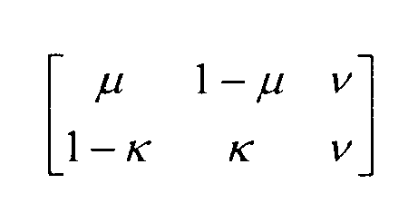
zu berechnen, wobei G eine von der Audioquelle von Spuren abgeleitete Energiematrix ist, D eine von den Abwärtsmischinformationen abgeleitete Abwärtsmischmatrix ist, A2 eine reduzierte Aufbereitungsmatrix ist und "*" die komplex konjugierte Operation angibt. - Der Audiosynthetisierer gemäß Anspruch 43, bei dem die parametrisierte Stereoaufbereitungsmatrix A2 wie folgt bestimmt wird:
wobei µ, v, und κ echtwertige Parameter sind, die gemäß Position und Volumen eines oder mehrerer Quellenaudioobjekte festgelegt werden sollen. - Audiosynthetisierungsverfahren zum Erzeugen von Ausgangsdaten unter Verwendung eines codierten Audioobjektsignals, wobei das codierte Audioobjektsignal Objektparameter (95) für eine Mehrzahl von Audioobjekten und Abwärtsmischinformationen (97) umfasst, mit folgenden Schritten:Empfangen der Objektparameter (95), wobei die Objektparameter (95) Annäherungen von Objektenergien der Mehrzahl von Audioobjekten und Korrelationsdaten für ein Stereoobjekt umfassen, undErzeugen der Ausgangsdaten, die zum Herstellen einer Mehrzahl von Ausgangskanälen einer vordefinierten Audioausgangskonfiguration, die die Mehrzahl von Audioobjekten darstellt, verwendbar sind, wobei die Mehrzahl von Audioobjekten ein Stereoobjekt umfasst, das durch zwei Audioobjekte dargestellt wird, die eine gewisse Nicht-Null-Korrelation aufweisen, durch Verwenden der Abwärtsmischinformationen (97), die eine Verteilung der Mehrzahl von Audioobjekten auf zumindest zwei Abwärtsmischkanäle angeben, und der Objektparameter (95) für die Audioobjekte.
- Codiertes Audioobjektsignal, das Abwärtsmischinformationen umfasst, die eine Verteilung einer Mehrzahl von Audioobjekten auf zumindest zwei Abwärtsmischkanäle angeben, wobei das codierte Audioobjektsignal ferner Objektparameter (95) umfasst, wobei die Objektparameter (95) Annäherungen von Objektenergien einer Mehrzahl von Audioobjekten und Korrelationsdaten für ein Stereoobjekt umfassen, wobei die Mehrzahl von Audioobjekten ein Stereoobjekt umfasst, das durch zwei Audioobjekte dargestellt wird, die eine gewisse Nicht-Null-Korrelation aufweisen, und wobei die Objektparameter (95) derart sind, dass eine Rekonstruktion der Audioobjekte unter Verwendung der Objektparameter und der zumindest zwei Abwärtsmischkanäle möglich ist.
- Codiertes Audioobjektsignal gemäß Anspruch 49, das auf einem computerlesbaren Speichermedium gespeichert ist.
- Computerprogramm zum Ausführen, wenn es auf einem Computer abläuft, eines Verfahrens gemäß einem der Verfahren der Ansprüche 18 oder 47.
Priority Applications (3)
| Application Number | Priority Date | Filing Date | Title |
|---|---|---|---|
| EP11153938.3A EP2372701B1 (de) | 2006-10-16 | 2007-10-05 | Verbesserte Kodierungs- und Parameterdarstellung von auf mehreren Kanälen abwärtsgemischter Objektkodierung |
| EP09004406A EP2068307B1 (de) | 2006-10-16 | 2007-10-05 | Verbesserte Kodierungs- und Parameterdarstellung von mehrkanaliger abwärtsgemischter Objektkodierung |
| PL09004406T PL2068307T3 (pl) | 2006-10-16 | 2007-10-05 | Udoskonalony sposób kodowania i odtwarzania parametrów w wielokanałowym kodowaniu obiektów poddanych procesowi downmiksu |
Applications Claiming Priority (2)
| Application Number | Priority Date | Filing Date | Title |
|---|---|---|---|
| US82964906P | 2006-10-16 | 2006-10-16 | |
| PCT/EP2007/008683 WO2008046531A1 (en) | 2006-10-16 | 2007-10-05 | Enhanced coding and parameter representation of multichannel downmixed object coding |
Related Child Applications (3)
| Application Number | Title | Priority Date | Filing Date |
|---|---|---|---|
| EP09004406A Division EP2068307B1 (de) | 2006-10-16 | 2007-10-05 | Verbesserte Kodierungs- und Parameterdarstellung von mehrkanaliger abwärtsgemischter Objektkodierung |
| EP09004406.6 Division-Into | 2009-03-26 | ||
| EP11153938.3 Division-Into | 2011-02-10 |
Publications (2)
| Publication Number | Publication Date |
|---|---|
| EP2054875A1 EP2054875A1 (de) | 2009-05-06 |
| EP2054875B1 true EP2054875B1 (de) | 2011-03-23 |
Family
ID=38810466
Family Applications (3)
| Application Number | Title | Priority Date | Filing Date |
|---|---|---|---|
| EP09004406A Active EP2068307B1 (de) | 2006-10-16 | 2007-10-05 | Verbesserte Kodierungs- und Parameterdarstellung von mehrkanaliger abwärtsgemischter Objektkodierung |
| EP11153938.3A Active EP2372701B1 (de) | 2006-10-16 | 2007-10-05 | Verbesserte Kodierungs- und Parameterdarstellung von auf mehreren Kanälen abwärtsgemischter Objektkodierung |
| EP07818759A Active EP2054875B1 (de) | 2006-10-16 | 2007-10-05 | Erweiterte codierung und parameterrepräsentation einer mehrkanaligen heruntergemischten objektcodierung |
Family Applications Before (2)
| Application Number | Title | Priority Date | Filing Date |
|---|---|---|---|
| EP09004406A Active EP2068307B1 (de) | 2006-10-16 | 2007-10-05 | Verbesserte Kodierungs- und Parameterdarstellung von mehrkanaliger abwärtsgemischter Objektkodierung |
| EP11153938.3A Active EP2372701B1 (de) | 2006-10-16 | 2007-10-05 | Verbesserte Kodierungs- und Parameterdarstellung von auf mehreren Kanälen abwärtsgemischter Objektkodierung |
Country Status (21)
| Country | Link |
|---|---|
| US (2) | US9565509B2 (de) |
| EP (3) | EP2068307B1 (de) |
| JP (3) | JP5270557B2 (de) |
| KR (2) | KR101012259B1 (de) |
| CN (3) | CN101529501B (de) |
| AT (2) | ATE536612T1 (de) |
| AU (2) | AU2007312598B2 (de) |
| BR (1) | BRPI0715559B1 (de) |
| CA (3) | CA2874454C (de) |
| DE (1) | DE602007013415D1 (de) |
| ES (1) | ES2378734T3 (de) |
| MX (1) | MX2009003570A (de) |
| MY (1) | MY145497A (de) |
| NO (1) | NO340450B1 (de) |
| PL (1) | PL2068307T3 (de) |
| PT (1) | PT2372701E (de) |
| RU (1) | RU2430430C2 (de) |
| SG (1) | SG175632A1 (de) |
| TW (1) | TWI347590B (de) |
| UA (1) | UA94117C2 (de) |
| WO (1) | WO2008046531A1 (de) |
Cited By (2)
| Publication number | Priority date | Publication date | Assignee | Title |
|---|---|---|---|---|
| RU2618383C2 (ru) * | 2011-11-01 | 2017-05-03 | Конинклейке Филипс Н.В. | Кодирование и декодирование аудиообъектов |
| US11869517B2 (en) | 2018-05-31 | 2024-01-09 | Huawei Technologies Co., Ltd. | Downmixed signal calculation method and apparatus |
Families Citing this family (143)
| Publication number | Priority date | Publication date | Assignee | Title |
|---|---|---|---|---|
| EP1927102A2 (de) * | 2005-06-03 | 2008-06-04 | Dolby Laboratories Licensing Corporation | Anordnung und verfahren zum kodieren von audiosignale mit hilfe von dekodierungsinstructionen |
| KR20080093422A (ko) * | 2006-02-09 | 2008-10-21 | 엘지전자 주식회사 | 오브젝트 기반 오디오 신호의 부호화 및 복호화 방법과 그장치 |
| KR100917843B1 (ko) | 2006-09-29 | 2009-09-18 | 한국전자통신연구원 | 다양한 채널로 구성된 다객체 오디오 신호의 부호화 및복호화 장치 및 방법 |
| JP5232791B2 (ja) * | 2006-10-12 | 2013-07-10 | エルジー エレクトロニクス インコーポレイティド | ミックス信号処理装置及びその方法 |
| KR101012259B1 (ko) | 2006-10-16 | 2011-02-08 | 돌비 스웨덴 에이비 | 멀티채널 다운믹스된 객체 코딩의 개선된 코딩 및 파라미터 표현 |
| JP5337941B2 (ja) | 2006-10-16 | 2013-11-06 | フラウンホッファー−ゲゼルシャフト ツァ フェルダールング デァ アンゲヴァンテン フォアシュンク エー.ファオ | マルチチャネル・パラメータ変換のための装置および方法 |
| US8571875B2 (en) | 2006-10-18 | 2013-10-29 | Samsung Electronics Co., Ltd. | Method, medium, and apparatus encoding and/or decoding multichannel audio signals |
| EP2095365A4 (de) * | 2006-11-24 | 2009-11-18 | Lg Electronics Inc | Verfahren zum codieren und decodieren eines audiosignals auf objektbasis und vorrichtung dafür |
| WO2008069593A1 (en) | 2006-12-07 | 2008-06-12 | Lg Electronics Inc. | A method and an apparatus for processing an audio signal |
| CN103137130B (zh) * | 2006-12-27 | 2016-08-17 | 韩国电子通信研究院 | 用于创建空间线索信息的代码转换设备 |
| EP2111617B1 (de) * | 2007-02-14 | 2013-09-04 | LG Electronics Inc. | Verfahren zur audiodekodierung und dementsprechende vorrichtung |
| US20100241434A1 (en) * | 2007-02-20 | 2010-09-23 | Kojiro Ono | Multi-channel decoding device, multi-channel decoding method, program, and semiconductor integrated circuit |
| WO2008111773A1 (en) | 2007-03-09 | 2008-09-18 | Lg Electronics Inc. | A method and an apparatus for processing an audio signal |
| KR20080082917A (ko) | 2007-03-09 | 2008-09-12 | 엘지전자 주식회사 | 오디오 신호 처리 방법 및 이의 장치 |
| EP2130304A4 (de) * | 2007-03-16 | 2012-04-04 | Lg Electronics Inc | Verfahren und vorrichtung zum verarbeiten eines audiosignals |
| EP3712888B1 (de) * | 2007-03-30 | 2024-05-08 | Electronics and Telecommunications Research Institute | Verfahren und vorrichtungen zur codierung und decodierung von multiobjektaudiosignal mit multikanal |
| CN101836249B (zh) | 2007-09-06 | 2012-11-28 | Lg电子株式会社 | 解码音频信号的方法和装置 |
| JP5883561B2 (ja) * | 2007-10-17 | 2016-03-15 | フラウンホッファー−ゲゼルシャフト ツァ フェルダールング デァ アンゲヴァンテン フォアシュンク エー.ファオ | アップミックスを使用した音声符号器 |
| WO2009068087A1 (en) * | 2007-11-27 | 2009-06-04 | Nokia Corporation | Multichannel audio coding |
| EP2238589B1 (de) * | 2007-12-09 | 2017-10-25 | LG Electronics Inc. | Verfahren und vorrichtung zum verarbeiten eines signals |
| KR101597375B1 (ko) | 2007-12-21 | 2016-02-24 | 디티에스 엘엘씨 | 오디오 신호의 인지된 음량을 조절하기 위한 시스템 |
| JP5340261B2 (ja) * | 2008-03-19 | 2013-11-13 | パナソニック株式会社 | ステレオ信号符号化装置、ステレオ信号復号装置およびこれらの方法 |
| KR101461685B1 (ko) * | 2008-03-31 | 2014-11-19 | 한국전자통신연구원 | 다객체 오디오 신호의 부가정보 비트스트림 생성 방법 및 장치 |
| WO2009141775A1 (en) * | 2008-05-23 | 2009-11-26 | Koninklijke Philips Electronics N.V. | A parametric stereo upmix apparatus, a parametric stereo decoder, a parametric stereo downmix apparatus, a parametric stereo encoder |
| US8315396B2 (en) * | 2008-07-17 | 2012-11-20 | Fraunhofer-Gesellschaft Zur Foerderung Der Angewandten Forschung E.V. | Apparatus and method for generating audio output signals using object based metadata |
| US8311810B2 (en) * | 2008-07-29 | 2012-11-13 | Panasonic Corporation | Reduced delay spatial coding and decoding apparatus and teleconferencing system |
| KR20110049863A (ko) * | 2008-08-14 | 2011-05-12 | 돌비 레버러토리즈 라이쎈싱 코오포레이션 | 오디오 신호 트랜스포맷팅 |
| US8861739B2 (en) | 2008-11-10 | 2014-10-14 | Nokia Corporation | Apparatus and method for generating a multichannel signal |
| WO2010064877A2 (en) | 2008-12-05 | 2010-06-10 | Lg Electronics Inc. | A method and an apparatus for processing an audio signal |
| KR20100065121A (ko) * | 2008-12-05 | 2010-06-15 | 엘지전자 주식회사 | 오디오 신호 처리 방법 및 장치 |
| EP2395504B1 (de) * | 2009-02-13 | 2013-09-18 | Huawei Technologies Co., Ltd. | Stereokodierungsverfahren und -vorrichtung |
| CN105225667B (zh) * | 2009-03-17 | 2019-04-05 | 杜比国际公司 | 编码器系统、解码器系统、编码方法和解码方法 |
| GB2470059A (en) * | 2009-05-08 | 2010-11-10 | Nokia Corp | Multi-channel audio processing using an inter-channel prediction model to form an inter-channel parameter |
| JP2011002574A (ja) * | 2009-06-17 | 2011-01-06 | Nippon Hoso Kyokai <Nhk> | 3次元音響符号化装置、3次元音響復号装置、符号化プログラム及び復号プログラム |
| US20100324915A1 (en) * | 2009-06-23 | 2010-12-23 | Electronic And Telecommunications Research Institute | Encoding and decoding apparatuses for high quality multi-channel audio codec |
| KR101283783B1 (ko) * | 2009-06-23 | 2013-07-08 | 한국전자통신연구원 | 고품질 다채널 오디오 부호화 및 복호화 장치 |
| US8538042B2 (en) | 2009-08-11 | 2013-09-17 | Dts Llc | System for increasing perceived loudness of speakers |
| JP5345024B2 (ja) * | 2009-08-28 | 2013-11-20 | 日本放送協会 | 3次元音響符号化装置、3次元音響復号装置、符号化プログラム及び復号プログラム |
| PL2489037T3 (pl) * | 2009-10-16 | 2022-03-07 | Fraunhofer-Gesellschaft zur Förderung der angewandten Forschung e.V. | Urządzenie, sposób i program komputerowy do dostarczania regulowanych parametrów |
| CN102257567B (zh) * | 2009-10-21 | 2014-05-07 | 松下电器产业株式会社 | 音响信号处理装置、音响编码装置及音响解码装置 |
| KR20110049068A (ko) * | 2009-11-04 | 2011-05-12 | 삼성전자주식회사 | 멀티 채널 오디오 신호의 부호화/복호화 장치 및 방법 |
| JP5645951B2 (ja) * | 2009-11-20 | 2014-12-24 | フラウンホッファー−ゲゼルシャフト ツァ フェルダールング デァ アンゲヴァンテン フォアシュンク エー.ファオ | ダウンミックス信号表現に基づくアップミックス信号を提供する装置、マルチチャネルオーディオ信号を表しているビットストリームを提供する装置、方法、コンピュータプログラム、および線形結合パラメータを使用してマルチチャネルオーディオ信号を表しているビットストリーム |
| WO2011071928A2 (en) * | 2009-12-07 | 2011-06-16 | Pixel Instruments Corporation | Dialogue detector and correction |
| EP2511908A4 (de) * | 2009-12-11 | 2013-07-31 | Korea Electronics Telecomm | Audioautorenvorrichtung und audiowiedergabevorrichtung für einen objektbasierten audiodienst sowie audioautorenverfahren und audiowiedergabeverfahren damit |
| EP2522016A4 (de) * | 2010-01-06 | 2015-04-22 | Lg Electronics Inc | Vorrichtung zur verarbeitung eines audiosignals und verfahren dafür |
| CN102859590B (zh) * | 2010-02-24 | 2015-08-19 | 弗劳恩霍夫应用研究促进协会 | 产生增强下混频信号的装置、产生增强下混频信号的方法以及计算机程序 |
| US10158958B2 (en) | 2010-03-23 | 2018-12-18 | Dolby Laboratories Licensing Corporation | Techniques for localized perceptual audio |
| CN113490133B (zh) | 2010-03-23 | 2023-05-02 | 杜比实验室特许公司 | 音频再现方法和声音再现系统 |
| JP5604933B2 (ja) * | 2010-03-30 | 2014-10-15 | 富士通株式会社 | ダウンミクス装置およびダウンミクス方法 |
| KR101698439B1 (ko) | 2010-04-09 | 2017-01-20 | 돌비 인터네셔널 에이비 | Mdct-기반의 복소수 예측 스테레오 코딩 |
| WO2011132368A1 (ja) * | 2010-04-19 | 2011-10-27 | パナソニック株式会社 | 符号化装置、復号装置、符号化方法及び復号方法 |
| KR20120038311A (ko) | 2010-10-13 | 2012-04-23 | 삼성전자주식회사 | 공간 파라미터 부호화 장치 및 방법,그리고 공간 파라미터 복호화 장치 및 방법 |
| US9313599B2 (en) | 2010-11-19 | 2016-04-12 | Nokia Technologies Oy | Apparatus and method for multi-channel signal playback |
| US9055371B2 (en) | 2010-11-19 | 2015-06-09 | Nokia Technologies Oy | Controllable playback system offering hierarchical playback options |
| US9456289B2 (en) | 2010-11-19 | 2016-09-27 | Nokia Technologies Oy | Converting multi-microphone captured signals to shifted signals useful for binaural signal processing and use thereof |
| KR20120071072A (ko) * | 2010-12-22 | 2012-07-02 | 한국전자통신연구원 | 객체 기반 오디오를 제공하는 방송 송신 장치 및 방법, 그리고 방송 재생 장치 및 방법 |
| BR112013026850B1 (pt) | 2011-04-20 | 2021-02-23 | Panasonic Intellectual Property Corporation Of America | Aparelhos de codificação e decodificação de áudio/fala e métodos decodificação e decodificação de áudio/fala |
| WO2013073810A1 (ko) * | 2011-11-14 | 2013-05-23 | 한국전자통신연구원 | 스케일러블 다채널 오디오 신호를 지원하는 부호화 장치 및 복호화 장치, 상기 장치가 수행하는 방법 |
| KR20130093798A (ko) | 2012-01-02 | 2013-08-23 | 한국전자통신연구원 | 다채널 신호 부호화 및 복호화 장치 및 방법 |
| CN108810744A (zh) | 2012-04-05 | 2018-11-13 | 诺基亚技术有限公司 | 柔性的空间音频捕捉设备 |
| US9312829B2 (en) | 2012-04-12 | 2016-04-12 | Dts Llc | System for adjusting loudness of audio signals in real time |
| US9622014B2 (en) | 2012-06-19 | 2017-04-11 | Dolby Laboratories Licensing Corporation | Rendering and playback of spatial audio using channel-based audio systems |
| EP3748632A1 (de) * | 2012-07-09 | 2020-12-09 | Koninklijke Philips N.V. | Codierung und decodierung von audiosignalen |
| US9190065B2 (en) | 2012-07-15 | 2015-11-17 | Qualcomm Incorporated | Systems, methods, apparatus, and computer-readable media for three-dimensional audio coding using basis function coefficients |
| US9516446B2 (en) | 2012-07-20 | 2016-12-06 | Qualcomm Incorporated | Scalable downmix design for object-based surround codec with cluster analysis by synthesis |
| US9761229B2 (en) | 2012-07-20 | 2017-09-12 | Qualcomm Incorporated | Systems, methods, apparatus, and computer-readable media for audio object clustering |
| US9564138B2 (en) | 2012-07-31 | 2017-02-07 | Intellectual Discovery Co., Ltd. | Method and device for processing audio signal |
| KR101660004B1 (ko) * | 2012-08-03 | 2016-09-27 | 프라운호퍼 게젤샤프트 쭈르 푀르데룽 데어 안겐반텐 포르슝 에. 베. | 멀티채널 다운믹스/업믹스 케이스들에 대해 매개변수 개념을 이용한 멀티-인스턴스 공간-오디오-오브젝트-코딩을 위한 디코더 및 방법 |
| US9489954B2 (en) * | 2012-08-07 | 2016-11-08 | Dolby Laboratories Licensing Corporation | Encoding and rendering of object based audio indicative of game audio content |
| KR102033985B1 (ko) * | 2012-08-10 | 2019-10-18 | 프라운호퍼 게젤샤프트 쭈르 푀르데룽 데어 안겐반텐 포르슝 에. 베. | 공간적 오디오 객체 코딩에 오디오 정보를 적응시키기 위한 장치 및 방법 |
| KR20140027831A (ko) * | 2012-08-27 | 2014-03-07 | 삼성전자주식회사 | 오디오 신호 전송 장치 및 그의 오디오 신호 전송 방법, 그리고 오디오 신호 수신 장치 및 그의 오디오 소스 추출 방법 |
| EP2717262A1 (de) | 2012-10-05 | 2014-04-09 | Fraunhofer-Gesellschaft zur Förderung der angewandten Forschung e.V. | Codierer, Decodierer und Verfahren für signalabhängige Zoomumwandlung beim Spatial-Audio-Object-Coding |
| BR112015013154B1 (pt) * | 2012-12-04 | 2022-04-26 | Samsung Electronics Co., Ltd | Aparelho fornecedor de áudio, e método fornecedor de áudio |
| WO2014111765A1 (en) * | 2013-01-15 | 2014-07-24 | Koninklijke Philips N.V. | Binaural audio processing |
| JP6179122B2 (ja) * | 2013-02-20 | 2017-08-16 | 富士通株式会社 | オーディオ符号化装置、オーディオ符号化方法、オーディオ符号化プログラム |
| EP2974010B1 (de) | 2013-03-15 | 2021-08-18 | DTS, Inc. | Automatische mehrkanalige musikmischung aus mehreren audioquellen |
| EP2982139A4 (de) | 2013-04-04 | 2016-11-23 | Nokia Technologies Oy | Audiovisuelle verarbeitungsvorrichtung |
| US9478224B2 (en) | 2013-04-05 | 2016-10-25 | Dolby International Ab | Audio processing system |
| DK2981963T3 (en) | 2013-04-05 | 2017-02-27 | Dolby Laboratories Licensing Corp | COMPRESSION APPARATUS AND PROCEDURE TO REDUCE QUANTIZATION NOISE USING ADVANCED SPECTRAL EXTENSION |
| US9905231B2 (en) | 2013-04-27 | 2018-02-27 | Intellectual Discovery Co., Ltd. | Audio signal processing method |
| EP2804176A1 (de) | 2013-05-13 | 2014-11-19 | Fraunhofer-Gesellschaft zur Förderung der angewandten Forschung e.V. | Trennung von Audio-Objekt aus einem Mischsignal mit objektspezifischen Zeit- und Frequenzauflösungen |
| US9706324B2 (en) | 2013-05-17 | 2017-07-11 | Nokia Technologies Oy | Spatial object oriented audio apparatus |
| RU2630754C2 (ru) * | 2013-05-24 | 2017-09-12 | Долби Интернешнл Аб | Эффективное кодирование звуковых сцен, содержащих звуковые объекты |
| CN105229731B (zh) * | 2013-05-24 | 2017-03-15 | 杜比国际公司 | 根据下混的音频场景的重构 |
| BR112015028914B1 (pt) * | 2013-05-24 | 2021-12-07 | Dolby International Ab | Método e aparelho para reconstruir um bloco de tempo/frequência de objetos de áudio n, método e codificador para gerar pelo menos um parâmetro de ponderação, e meio legível por computador |
| BR112015029113B1 (pt) * | 2013-05-24 | 2022-03-22 | Dolby International Ab | Método para a codificação de objetos de áudio como um fluxo de dados, método para a reconstrução de objetos de áudio com base em um fluxo de dados e decodificador para reconstruir objetos de áudio com base em um fluxo de dados |
| MY204539A (en) | 2013-05-24 | 2024-09-03 | Dolby Int Ab | Coding of audio scenes |
| SG10201710019SA (en) * | 2013-05-24 | 2018-01-30 | Dolby Int Ab | Audio Encoder And Decoder |
| TWI615834B (zh) * | 2013-05-31 | 2018-02-21 | Sony Corp | 編碼裝置及方法、解碼裝置及方法、以及程式 |
| JP6377730B2 (ja) * | 2013-06-05 | 2018-08-22 | ドルビー・インターナショナル・アーベー | オーディオ信号を符号化する方法及び装置並びにオーディオ信号を復号する方法及び装置 |
| CN104240711B (zh) | 2013-06-18 | 2019-10-11 | 杜比实验室特许公司 | 用于生成自适应音频内容的方法、系统和装置 |
| EP3017446B1 (de) | 2013-07-05 | 2021-08-25 | Dolby International AB | Verbesserte klangfeldcodierung mittels erzeugung parametrischer komponenten |
| EP3023984A4 (de) * | 2013-07-15 | 2017-03-08 | Electronics and Telecommunications Research Institute | Codierer und codierungsverfahren für mehrkanalsignal sowie decoder und decodierungsverfahren für mehrkanalsignal |
| SG11201600466PA (en) | 2013-07-22 | 2016-02-26 | Fraunhofer Ges Forschung | Multi-channel audio decoder, multi-channel audio encoder, methods, computer program and encoded audio representation using a decorrelation of rendered audio signals |
| EP2830334A1 (de) | 2013-07-22 | 2015-01-28 | Fraunhofer-Gesellschaft zur Förderung der angewandten Forschung e.V. | Mehrkanaliger Audiodecodierer, mehrkanaliger Audiocodierer, Verfahren, Computerprogramm und codierte Audiodarstellung unter Verwendung einer Dekorrelation gerenderter Audiosignale |
| EP2830045A1 (de) * | 2013-07-22 | 2015-01-28 | Fraunhofer-Gesellschaft zur Förderung der angewandten Forschung e.V. | Konzept zur Audiocodierung und Audiodecodierung für Audiokanäle und Audioobjekte |
| EP2830054A1 (de) | 2013-07-22 | 2015-01-28 | Fraunhofer Gesellschaft zur Förderung der angewandten Forschung e.V. | Audiocodierer, Audiodecodierer und zugehörige Verfahren unter Verwendung von Zweikanalverarbeitung in einem intelligenten Lückenfüllkontext |
| EP2830046A1 (de) | 2013-07-22 | 2015-01-28 | Fraunhofer-Gesellschaft zur Förderung der angewandten Forschung e.V. | Vorrichtung und Verfahren zum Decodieren eines codierten Audiosignals zur Gewinnung von modifizierten Ausgangssignalen |
| EP2830047A1 (de) | 2013-07-22 | 2015-01-28 | Fraunhofer-Gesellschaft zur Förderung der angewandten Forschung e.V. | Vorrichtung und Verfahren zur verzögerungsarmen Codierung von Objektmetadaten |
| EP2830048A1 (de) | 2013-07-22 | 2015-01-28 | Fraunhofer-Gesellschaft zur Förderung der angewandten Forschung e.V. | Vorrichtung und Verfahren zur Realisierung eines SAOC-Downmix von 3D-Audioinhalt |
| EP3028273B1 (de) * | 2013-07-31 | 2019-09-11 | Dolby Laboratories Licensing Corporation | Verarbeitung von räumlich diffusen oder grossen audioobjekten |
| RU2639952C2 (ru) | 2013-08-28 | 2017-12-25 | Долби Лабораторис Лайсэнзин Корпорейшн | Гибридное усиление речи с кодированием формы сигнала и параметрическим кодированием |
| KR102243395B1 (ko) * | 2013-09-05 | 2021-04-22 | 한국전자통신연구원 | 오디오 부호화 장치 및 방법, 오디오 복호화 장치 및 방법, 오디오 재생 장치 |
| TWI774136B (zh) | 2013-09-12 | 2022-08-11 | 瑞典商杜比國際公司 | 多聲道音訊系統中之解碼方法、解碼裝置、包含用於執行解碼方法的指令之非暫態電腦可讀取的媒體之電腦程式產品、包含解碼裝置的音訊系統 |
| EP3293734B1 (de) | 2013-09-12 | 2019-05-15 | Dolby International AB | Decodierung von mehrkanal-audioinhalten |
| TWI557724B (zh) * | 2013-09-27 | 2016-11-11 | 杜比實驗室特許公司 | 用於將 n 聲道音頻節目編碼之方法、用於恢復 n 聲道音頻節目的 m 個聲道之方法、被配置成將 n 聲道音頻節目編碼之音頻編碼器及被配置成執行 n 聲道音頻節目的恢復之解碼器 |
| BR112016007264B1 (pt) * | 2013-10-09 | 2021-12-28 | Sony Corporation | Dispositivos e métodos de codificação e de decodificação, e, meios de armazenamento legíveis por computador |
| KR102244379B1 (ko) * | 2013-10-21 | 2021-04-26 | 돌비 인터네셔널 에이비 | 오디오 신호들의 파라메트릭 재구성 |
| JP6396452B2 (ja) * | 2013-10-21 | 2018-09-26 | ドルビー・インターナショナル・アーベー | オーディオ・エンコーダおよびデコーダ |
| EP2866227A1 (de) | 2013-10-22 | 2015-04-29 | Fraunhofer-Gesellschaft zur Förderung der angewandten Forschung e.V. | Verfahren zur Dekodierung und Kodierung einer Downmix-Matrix, Verfahren zur Darstellung von Audioinhalt, Kodierer und Dekodierer für eine Downmix-Matrix, Audiokodierer und Audiodekodierer |
| EP2866475A1 (de) | 2013-10-23 | 2015-04-29 | Thomson Licensing | Verfahren und Vorrichtung zur Decodierung einer Audioschallfelddarstellung für Audiowiedergabe mittels 2D-Einstellungen |
| KR102107554B1 (ko) * | 2013-11-18 | 2020-05-07 | 인포뱅크 주식회사 | 네트워크를 이용한 멀티미디어 합성 방법 |
| EP2879131A1 (de) | 2013-11-27 | 2015-06-03 | Fraunhofer-Gesellschaft zur Förderung der angewandten Forschung e.V. | Dekodierer, Kodierer und Verfahren für informierte Lautstärkenschätzung in objektbasierten Audiocodierungssystemen |
| EP3092642B1 (de) | 2014-01-09 | 2018-05-16 | Dolby Laboratories Licensing Corporation | Räumliche fehlermetriken von audioinhalten |
| US20170287505A1 (en) * | 2014-09-03 | 2017-10-05 | Samsung Electronics Co., Ltd. | Method and apparatus for learning and recognizing audio signal |
| US9774974B2 (en) * | 2014-09-24 | 2017-09-26 | Electronics And Telecommunications Research Institute | Audio metadata providing apparatus and method, and multichannel audio data playback apparatus and method to support dynamic format conversion |
| TWI587286B (zh) | 2014-10-31 | 2017-06-11 | 杜比國際公司 | 音頻訊號之解碼和編碼的方法及系統、電腦程式產品、與電腦可讀取媒體 |
| EP3067885A1 (de) | 2015-03-09 | 2016-09-14 | Fraunhofer-Gesellschaft zur Förderung der angewandten Forschung e.V. | Vorrichtung und verfahren zur verschlüsselung oder entschlüsselung eines mehrkanalsignals |
| KR102539973B1 (ko) * | 2015-07-16 | 2023-06-05 | 소니그룹주식회사 | 정보 처리 장치 및 방법, 및 프로그램 |
| WO2017035281A2 (en) * | 2015-08-25 | 2017-03-02 | Dolby International Ab | Audio encoding and decoding using presentation transform parameters |
| US10319385B2 (en) | 2015-09-25 | 2019-06-11 | Voiceage Corporation | Method and system for encoding left and right channels of a stereo sound signal selecting between two and four sub-frames models depending on the bit budget |
| US12125492B2 (en) | 2015-09-25 | 2024-10-22 | Voiceage Coproration | Method and system for decoding left and right channels of a stereo sound signal |
| US9961467B2 (en) * | 2015-10-08 | 2018-05-01 | Qualcomm Incorporated | Conversion from channel-based audio to HOA |
| CA3080981C (en) | 2015-11-17 | 2023-07-11 | Dolby Laboratories Licensing Corporation | Headtracking for parametric binaural output system and method |
| RU2722391C2 (ru) * | 2015-11-17 | 2020-05-29 | Долби Лэборетериз Лайсенсинг Корпорейшн | Система и способ слежения за движением головы для получения параметрического бинаурального выходного сигнала |
| KR102640940B1 (ko) * | 2016-01-27 | 2024-02-26 | 돌비 레버러토리즈 라이쎈싱 코오포레이션 | 음향 환경 시뮬레이션 |
| US10158758B2 (en) | 2016-11-02 | 2018-12-18 | International Business Machines Corporation | System and method for monitoring and visualizing emotions in call center dialogs at call centers |
| US10135979B2 (en) * | 2016-11-02 | 2018-11-20 | International Business Machines Corporation | System and method for monitoring and visualizing emotions in call center dialogs by call center supervisors |
| CN106604199B (zh) * | 2016-12-23 | 2018-09-18 | 湖南国科微电子股份有限公司 | 一种数字音频信号的矩阵处理方法及装置 |
| GB201718341D0 (en) | 2017-11-06 | 2017-12-20 | Nokia Technologies Oy | Determination of targeted spatial audio parameters and associated spatial audio playback |
| US10650834B2 (en) | 2018-01-10 | 2020-05-12 | Savitech Corp. | Audio processing method and non-transitory computer readable medium |
| GB2572650A (en) | 2018-04-06 | 2019-10-09 | Nokia Technologies Oy | Spatial audio parameters and associated spatial audio playback |
| GB2574239A (en) | 2018-05-31 | 2019-12-04 | Nokia Technologies Oy | Signalling of spatial audio parameters |
| CN110970008A (zh) * | 2018-09-28 | 2020-04-07 | 广州灵派科技有限公司 | 一种嵌入式混音方法、装置、嵌入式设备及存储介质 |
| EP3881559B1 (de) | 2018-11-13 | 2024-02-14 | Dolby Laboratories Licensing Corporation | Audioverarbeitung in immersiven audiodiensten |
| EP4462821A3 (de) | 2018-11-13 | 2024-12-25 | Dolby Laboratories Licensing Corporation | Darstellung von räumlichem audio mittels eines audiosignals und zugehörige metadaten |
| MX2021015314A (es) * | 2019-06-14 | 2022-02-03 | Fraunhofer Ges Forschung | Codificacion y decodificacion de parametros. |
| JP7286876B2 (ja) | 2019-09-23 | 2023-06-05 | ドルビー ラボラトリーズ ライセンシング コーポレイション | 変換パラメータによるオーディオ符号化/復号化 |
| KR102079691B1 (ko) * | 2019-11-11 | 2020-02-19 | 인포뱅크 주식회사 | 네트워크를 이용한 멀티미디어 합성 단말기 |
| WO2021252748A1 (en) * | 2020-06-11 | 2021-12-16 | Dolby Laboratories Licensing Corporation | Encoding of multi-channel audio signals comprising downmixing of a primary and two or more scaled non-primary input channels |
| WO2022245076A1 (ko) * | 2021-05-21 | 2022-11-24 | 삼성전자 주식회사 | 다채널 오디오 신호 처리 장치 및 방법 |
| CN114463584B (zh) * | 2022-01-29 | 2023-03-24 | 北京百度网讯科技有限公司 | 图像处理、模型训练方法、装置、设备、存储介质及程序 |
| CN114501297B (zh) * | 2022-04-02 | 2022-09-02 | 北京荣耀终端有限公司 | 一种音频处理方法以及电子设备 |
Family Cites Families (62)
| Publication number | Priority date | Publication date | Assignee | Title |
|---|---|---|---|---|
| SG43996A1 (en) * | 1993-06-22 | 1997-11-14 | Thomson Brandt Gmbh | Method for obtaining a multi-channel decoder matrix |
| CN1129263C (zh) | 1994-02-17 | 2003-11-26 | 摩托罗拉公司 | 分组编码信号的方法和装置 |
| US6128597A (en) * | 1996-05-03 | 2000-10-03 | Lsi Logic Corporation | Audio decoder with a reconfigurable downmixing/windowing pipeline and method therefor |
| US5912976A (en) | 1996-11-07 | 1999-06-15 | Srs Labs, Inc. | Multi-channel audio enhancement system for use in recording and playback and methods for providing same |
| JP3743671B2 (ja) | 1997-11-28 | 2006-02-08 | 日本ビクター株式会社 | オーディオディスク及びオーディオ再生装置 |
| JP2005093058A (ja) | 1997-11-28 | 2005-04-07 | Victor Co Of Japan Ltd | オーディオ信号のエンコード方法及びデコード方法 |
| US6016473A (en) | 1998-04-07 | 2000-01-18 | Dolby; Ray M. | Low bit-rate spatial coding method and system |
| US6788880B1 (en) | 1998-04-16 | 2004-09-07 | Victor Company Of Japan, Ltd | Recording medium having a first area for storing an audio title set and a second area for storing a still picture set and apparatus for processing the recorded information |
| US6122619A (en) * | 1998-06-17 | 2000-09-19 | Lsi Logic Corporation | Audio decoder with programmable downmixing of MPEG/AC-3 and method therefor |
| EP1370114A3 (de) | 1999-04-07 | 2004-03-17 | Dolby Laboratories Licensing Corporation | Verbesserungen der Matrizierung für die verlustfreie Kodierung und Dekodierung |
| KR100392384B1 (ko) | 2001-01-13 | 2003-07-22 | 한국전자통신연구원 | 엠펙-2 데이터에 엠펙-4 데이터를 동기화시켜 전송하는장치 및 그 방법 |
| US7292901B2 (en) | 2002-06-24 | 2007-11-06 | Agere Systems Inc. | Hybrid multi-channel/cue coding/decoding of audio signals |
| JP2002369152A (ja) | 2001-06-06 | 2002-12-20 | Canon Inc | 画像処理装置、画像処理方法、画像処理プログラム及び画像処理プログラムが記憶されたコンピュータにより読み取り可能な記憶媒体 |
| WO2003024665A1 (en) | 2001-09-14 | 2003-03-27 | Corus Aluminium Walzprodukte Gmbh | Method of de-coating metallic coated scrap pieces |
| BRPI0308148A2 (pt) * | 2002-04-05 | 2016-06-21 | Koninkl Philips Electronics Nv | métodos e aparelhos para codificar n sinais de entrada e para decodificar dados codificados representativos de n sinais, formato de sinal, e, portador de gravação |
| JP3994788B2 (ja) | 2002-04-30 | 2007-10-24 | ソニー株式会社 | 伝達特性測定装置、伝達特性測定方法、及び伝達特性測定プログラム、並びに増幅装置 |
| BR0305434A (pt) | 2002-07-12 | 2004-09-28 | Koninkl Philips Electronics Nv | Métodos e arranjos para codificar e para decodificar um sinal de áudio multicanal, aparelhos para fornecer um sinal de áudio codificado e um sinal de áudio decodificado, sinal de áudio multicanal codificado, e, meio de armazenagem |
| WO2004008806A1 (en) | 2002-07-16 | 2004-01-22 | Koninklijke Philips Electronics N.V. | Audio coding |
| JP2004193877A (ja) | 2002-12-10 | 2004-07-08 | Sony Corp | 音像定位信号処理装置および音像定位信号処理方法 |
| KR20040060718A (ko) * | 2002-12-28 | 2004-07-06 | 삼성전자주식회사 | 오디오 스트림 믹싱 방법, 그 장치 및 그 정보저장매체 |
| EP1609335A2 (de) | 2003-03-24 | 2005-12-28 | Koninklijke Philips Electronics N.V. | Codierung eines haupt- und nebensignals, das ein mehrkanalsignal repräsentiert |
| US7447317B2 (en) | 2003-10-02 | 2008-11-04 | Fraunhofer-Gesellschaft Zur Foerderung Der Angewandten Forschung E.V | Compatible multi-channel coding/decoding by weighting the downmix channel |
| US7555009B2 (en) | 2003-11-14 | 2009-06-30 | Canon Kabushiki Kaisha | Data processing method and apparatus, and data distribution method and information processing apparatus |
| JP4378157B2 (ja) | 2003-11-14 | 2009-12-02 | キヤノン株式会社 | データ処理方法および装置 |
| US7805313B2 (en) | 2004-03-04 | 2010-09-28 | Agere Systems Inc. | Frequency-based coding of channels in parametric multi-channel coding systems |
| CN1938760B (zh) * | 2004-04-05 | 2012-05-23 | 皇家飞利浦电子股份有限公司 | 多通道编码器 |
| CN1947172B (zh) * | 2004-04-05 | 2011-08-03 | 皇家飞利浦电子股份有限公司 | 方法、装置、编码器设备、解码器设备以及音频系统 |
| SE0400998D0 (sv) | 2004-04-16 | 2004-04-16 | Cooding Technologies Sweden Ab | Method for representing multi-channel audio signals |
| US7391870B2 (en) | 2004-07-09 | 2008-06-24 | Fraunhofer-Gesellschaft Zur Foerderung Der Angewandten Forschung E V | Apparatus and method for generating a multi-channel output signal |
| TWI393121B (zh) * | 2004-08-25 | 2013-04-11 | 杜比實驗室特許公司 | 處理一組n個聲音信號之方法與裝置及與其相關聯之電腦程式 |
| WO2006025337A1 (ja) * | 2004-08-31 | 2006-03-09 | Matsushita Electric Industrial Co., Ltd. | ステレオ信号生成装置およびステレオ信号生成方法 |
| JP2006101248A (ja) | 2004-09-30 | 2006-04-13 | Victor Co Of Japan Ltd | 音場補正装置 |
| SE0402652D0 (sv) * | 2004-11-02 | 2004-11-02 | Coding Tech Ab | Methods for improved performance of prediction based multi- channel reconstruction |
| JP5106115B2 (ja) * | 2004-11-30 | 2012-12-26 | アギア システムズ インコーポレーテッド | オブジェクト・ベースのサイド情報を用いる空間オーディオのパラメトリック・コーディング |
| EP1691348A1 (de) | 2005-02-14 | 2006-08-16 | Ecole Polytechnique Federale De Lausanne | Parametrische kombinierte Kodierung von Audio-Quellen |
| US7573912B2 (en) | 2005-02-22 | 2009-08-11 | Fraunhofer-Gesellschaft Zur Foerderung Der Angewandten Forschunng E.V. | Near-transparent or transparent multi-channel encoder/decoder scheme |
| PL1866912T3 (pl) * | 2005-03-30 | 2011-03-31 | Koninl Philips Electronics Nv | Kodowanie wielokanałowego sygnału audio |
| US7991610B2 (en) | 2005-04-13 | 2011-08-02 | Fraunhofer-Gesellschaft Zur Foerderung Der Angewandten Forschung E.V. | Adaptive grouping of parameters for enhanced coding efficiency |
| US7961890B2 (en) | 2005-04-15 | 2011-06-14 | Fraunhofer-Gesellschaft Zur Foerderung Der Angewandten Forschung, E.V. | Multi-channel hierarchical audio coding with compact side information |
| US8214221B2 (en) | 2005-06-30 | 2012-07-03 | Lg Electronics Inc. | Method and apparatus for decoding an audio signal and identifying information included in the audio signal |
| US20070055510A1 (en) * | 2005-07-19 | 2007-03-08 | Johannes Hilpert | Concept for bridging the gap between parametric multi-channel audio coding and matrixed-surround multi-channel coding |
| MX2008001307A (es) | 2005-07-29 | 2008-03-19 | Lg Electronics Inc | Metodo para la senalizacion de informacion de division. |
| CA2620627C (en) * | 2005-08-30 | 2011-03-15 | Lg Electronics Inc. | Apparatus for encoding and decoding audio signal and method thereof |
| KR100857105B1 (ko) | 2005-09-14 | 2008-09-05 | 엘지전자 주식회사 | 오디오 신호의 디코딩 방법 및 장치 |
| EP1946310A4 (de) * | 2005-10-26 | 2011-03-09 | Lg Electronics Inc | Verfahren zum codieren und decodieren eines mehrkanal-audiosignals und vorrichtung dafür |
| KR100888474B1 (ko) * | 2005-11-21 | 2009-03-12 | 삼성전자주식회사 | 멀티채널 오디오 신호의 부호화/복호화 장치 및 방법 |
| KR100644715B1 (ko) * | 2005-12-19 | 2006-11-10 | 삼성전자주식회사 | 능동적 오디오 매트릭스 디코딩 방법 및 장치 |
| JP5161109B2 (ja) | 2006-01-19 | 2013-03-13 | エルジー エレクトロニクス インコーポレイティド | 信号デコーディング方法及び装置 |
| US8560303B2 (en) | 2006-02-03 | 2013-10-15 | Electronics And Telecommunications Research Institute | Apparatus and method for visualization of multichannel audio signals |
| CN101410891A (zh) | 2006-02-03 | 2009-04-15 | 韩国电子通信研究院 | 使用空间线索控制多目标或多声道音频信号的渲染的方法和装置 |
| KR20080093422A (ko) * | 2006-02-09 | 2008-10-21 | 엘지전자 주식회사 | 오브젝트 기반 오디오 신호의 부호화 및 복호화 방법과 그장치 |
| CA2646278A1 (en) | 2006-02-09 | 2007-08-16 | Lg Electronics Inc. | Method for encoding and decoding object-based audio signal and apparatus thereof |
| ATE532350T1 (de) * | 2006-03-24 | 2011-11-15 | Dolby Sweden Ab | Erzeugung räumlicher heruntermischungen aus parametrischen darstellungen mehrkanaliger signale |
| CN101411214B (zh) | 2006-03-28 | 2011-08-10 | 艾利森电话股份有限公司 | 用于多信道环绕声音的解码器的方法和装置 |
| US7965848B2 (en) | 2006-03-29 | 2011-06-21 | Dolby International Ab | Reduced number of channels decoding |
| ATE527833T1 (de) | 2006-05-04 | 2011-10-15 | Lg Electronics Inc | Verbesserung von stereo-audiosignalen mittels neuabmischung |
| EP2038878B1 (de) * | 2006-07-07 | 2012-01-18 | Fraunhofer-Gesellschaft zur Förderung der angewandten Forschung e.V. | Vorrichtung und verfahren zum kombinieren mehrerer parametrisch kodierter audioquellen |
| US20080235006A1 (en) | 2006-08-18 | 2008-09-25 | Lg Electronics, Inc. | Method and Apparatus for Decoding an Audio Signal |
| KR100917843B1 (ko) | 2006-09-29 | 2009-09-18 | 한국전자통신연구원 | 다양한 채널로 구성된 다객체 오디오 신호의 부호화 및복호화 장치 및 방법 |
| MX2008012315A (es) * | 2006-09-29 | 2008-10-10 | Lg Electronics Inc | Metodos y aparatos para codificar y descodificar señales de audio basados en objeto. |
| JP5232791B2 (ja) * | 2006-10-12 | 2013-07-10 | エルジー エレクトロニクス インコーポレイティド | ミックス信号処理装置及びその方法 |
| KR101012259B1 (ko) | 2006-10-16 | 2011-02-08 | 돌비 스웨덴 에이비 | 멀티채널 다운믹스된 객체 코딩의 개선된 코딩 및 파라미터 표현 |
-
2007
- 2007-10-05 KR KR1020097007957A patent/KR101012259B1/ko active Active
- 2007-10-05 DE DE602007013415T patent/DE602007013415D1/de active Active
- 2007-10-05 MY MYPI20091442A patent/MY145497A/en unknown
- 2007-10-05 AT AT09004406T patent/ATE536612T1/de active
- 2007-10-05 BR BRPI0715559-0A patent/BRPI0715559B1/pt active IP Right Grant
- 2007-10-05 UA UAA200903977A patent/UA94117C2/ru unknown
- 2007-10-05 EP EP09004406A patent/EP2068307B1/de active Active
- 2007-10-05 CN CN2007800383647A patent/CN101529501B/zh active Active
- 2007-10-05 MX MX2009003570A patent/MX2009003570A/es active IP Right Grant
- 2007-10-05 AU AU2007312598A patent/AU2007312598B2/en active Active
- 2007-10-05 WO PCT/EP2007/008683 patent/WO2008046531A1/en not_active Ceased
- 2007-10-05 ES ES09004406T patent/ES2378734T3/es active Active
- 2007-10-05 CN CN201310285571.XA patent/CN103400583B/zh active Active
- 2007-10-05 CA CA2874454A patent/CA2874454C/en active Active
- 2007-10-05 SG SG2011075256A patent/SG175632A1/en unknown
- 2007-10-05 PT PT111539383T patent/PT2372701E/pt unknown
- 2007-10-05 US US12/445,701 patent/US9565509B2/en active Active
- 2007-10-05 RU RU2009113055/09A patent/RU2430430C2/ru active
- 2007-10-05 EP EP11153938.3A patent/EP2372701B1/de active Active
- 2007-10-05 EP EP07818759A patent/EP2054875B1/de active Active
- 2007-10-05 CN CN201210276103.1A patent/CN102892070B/zh active Active
- 2007-10-05 PL PL09004406T patent/PL2068307T3/pl unknown
- 2007-10-05 CA CA2666640A patent/CA2666640C/en active Active
- 2007-10-05 JP JP2009532703A patent/JP5270557B2/ja active Active
- 2007-10-05 AT AT07818759T patent/ATE503245T1/de not_active IP Right Cessation
- 2007-10-05 CA CA2874451A patent/CA2874451C/en active Active
- 2007-10-05 KR KR1020107029462A patent/KR101103987B1/ko active Active
- 2007-10-11 TW TW096137940A patent/TWI347590B/zh active
-
2009
- 2009-05-14 NO NO20091901A patent/NO340450B1/no unknown
-
2011
- 2011-03-11 AU AU2011201106A patent/AU2011201106B2/en active Active
-
2012
- 2012-03-22 JP JP2012064886A patent/JP5297544B2/ja active Active
-
2013
- 2013-05-13 JP JP2013100865A patent/JP5592974B2/ja active Active
-
2016
- 2016-11-04 US US15/344,170 patent/US20170084285A1/en not_active Abandoned
Cited By (3)
| Publication number | Priority date | Publication date | Assignee | Title |
|---|---|---|---|---|
| RU2618383C2 (ru) * | 2011-11-01 | 2017-05-03 | Конинклейке Филипс Н.В. | Кодирование и декодирование аудиообъектов |
| US11869517B2 (en) | 2018-05-31 | 2024-01-09 | Huawei Technologies Co., Ltd. | Downmixed signal calculation method and apparatus |
| US12327567B2 (en) | 2018-05-31 | 2025-06-10 | Huawei Technologies Co., Ltd. | Downmixed signal calculation method and apparatus |
Also Published As
Similar Documents
| Publication | Publication Date | Title |
|---|---|---|
| EP2054875B1 (de) | Erweiterte codierung und parameterrepräsentation einer mehrkanaligen heruntergemischten objektcodierung | |
| EP2137725B1 (de) | Vorrichtung und verfahren zur synthetisierung eines ausgangssignals | |
| RU2485605C2 (ru) | Усовершенствованный метод кодирования и параметрического представления кодирования многоканального объекта после понижающего микширования | |
| HK1126888B (en) | Enhanced coding and parameter representation of multichannel downmixed object coding | |
| HK1133116B (en) | Enhanced coding and parameter representation of multichannel downmixed object coding | |
| HK1162736B (en) | Enhanced coding and parameter representation of multichannel downmixed object coding | |
| HK1142712B (en) | Apparatus and method for synthesizing an output signal |
Legal Events
| Date | Code | Title | Description |
|---|---|---|---|
| PUAI | Public reference made under article 153(3) epc to a published international application that has entered the european phase |
Free format text: ORIGINAL CODE: 0009012 |
|
| 17P | Request for examination filed |
Effective date: 20080327 |
|
| AK | Designated contracting states |
Kind code of ref document: A1 Designated state(s): AT BE BG CH CY CZ DE DK EE ES FI FR GB GR HU IE IS IT LI LT LU LV MC MT NL PL PT RO SE SI SK TR |
|
| AX | Request for extension of the european patent |
Extension state: AL BA HR MK RS |
|
| DAX | Request for extension of the european patent (deleted) | ||
| RIN1 | Information on inventor provided before grant (corrected) |
Inventor name: VILLEMOES, LARS Inventor name: ENGDEGARD, JONAS Inventor name: PURNHAGEN, HEIKO Inventor name: RESCH, BARBARA |
|
| 17Q | First examination report despatched |
Effective date: 20090804 |
|
| REG | Reference to a national code |
Ref country code: HK Ref legal event code: DE Ref document number: 1126888 Country of ref document: HK |
|
| GRAP | Despatch of communication of intention to grant a patent |
Free format text: ORIGINAL CODE: EPIDOSNIGR1 |
|
| GRAS | Grant fee paid |
Free format text: ORIGINAL CODE: EPIDOSNIGR3 |
|
| GRAA | (expected) grant |
Free format text: ORIGINAL CODE: 0009210 |
|
| AK | Designated contracting states |
Kind code of ref document: B1 Designated state(s): AT BE BG CH CY CZ DE DK EE ES FI FR GB GR HU IE IS IT LI LT LU LV MC MT NL PL PT RO SE SI SK TR |
|
| REG | Reference to a national code |
Ref country code: GB Ref legal event code: FG4D |
|
| REG | Reference to a national code |
Ref country code: CH Ref legal event code: EP |
|
| REG | Reference to a national code |
Ref country code: IE Ref legal event code: FG4D |
|
| REG | Reference to a national code |
Ref country code: CH Ref legal event code: NV Representative=s name: BOVARD AG |
|
| REF | Corresponds to: |
Ref document number: 602007013415 Country of ref document: DE Date of ref document: 20110505 Kind code of ref document: P |
|
| REG | Reference to a national code |
Ref country code: DE Ref legal event code: R096 Ref document number: 602007013415 Country of ref document: DE Effective date: 20110505 |
|
| REG | Reference to a national code |
Ref country code: NL Ref legal event code: T3 |
|
| REG | Reference to a national code |
Ref country code: SE Ref legal event code: TRGR |
|
| PG25 | Lapsed in a contracting state [announced via postgrant information from national office to epo] |
Ref country code: LT Free format text: LAPSE BECAUSE OF FAILURE TO SUBMIT A TRANSLATION OF THE DESCRIPTION OR TO PAY THE FEE WITHIN THE PRESCRIBED TIME-LIMIT Effective date: 20110323 Ref country code: GR Free format text: LAPSE BECAUSE OF FAILURE TO SUBMIT A TRANSLATION OF THE DESCRIPTION OR TO PAY THE FEE WITHIN THE PRESCRIBED TIME-LIMIT Effective date: 20110624 Ref country code: LV Free format text: LAPSE BECAUSE OF FAILURE TO SUBMIT A TRANSLATION OF THE DESCRIPTION OR TO PAY THE FEE WITHIN THE PRESCRIBED TIME-LIMIT Effective date: 20110323 |
|
| LTIE | Lt: invalidation of european patent or patent extension |
Effective date: 20110323 |
|
| PG25 | Lapsed in a contracting state [announced via postgrant information from national office to epo] |
Ref country code: AT Free format text: LAPSE BECAUSE OF FAILURE TO SUBMIT A TRANSLATION OF THE DESCRIPTION OR TO PAY THE FEE WITHIN THE PRESCRIBED TIME-LIMIT Effective date: 20110323 Ref country code: FI Free format text: LAPSE BECAUSE OF FAILURE TO SUBMIT A TRANSLATION OF THE DESCRIPTION OR TO PAY THE FEE WITHIN THE PRESCRIBED TIME-LIMIT Effective date: 20110323 Ref country code: SI Free format text: LAPSE BECAUSE OF FAILURE TO SUBMIT A TRANSLATION OF THE DESCRIPTION OR TO PAY THE FEE WITHIN THE PRESCRIBED TIME-LIMIT Effective date: 20110323 Ref country code: CY Free format text: LAPSE BECAUSE OF FAILURE TO SUBMIT A TRANSLATION OF THE DESCRIPTION OR TO PAY THE FEE WITHIN THE PRESCRIBED TIME-LIMIT Effective date: 20110323 Ref country code: BG Free format text: LAPSE BECAUSE OF FAILURE TO SUBMIT A TRANSLATION OF THE DESCRIPTION OR TO PAY THE FEE WITHIN THE PRESCRIBED TIME-LIMIT Effective date: 20110623 |
|
| PG25 | Lapsed in a contracting state [announced via postgrant information from national office to epo] |
Ref country code: BE Free format text: LAPSE BECAUSE OF FAILURE TO SUBMIT A TRANSLATION OF THE DESCRIPTION OR TO PAY THE FEE WITHIN THE PRESCRIBED TIME-LIMIT Effective date: 20110323 |
|
| REG | Reference to a national code |
Ref country code: CH Ref legal event code: PFA Owner name: DOLBY INTERNATIONAL AB Free format text: DOLBY SWEDEN AB#GAEVLEGATAN 12A#113 30 STOCKHOLM (SE) -TRANSFER TO- DOLBY INTERNATIONAL AB#C/O APOLLO BUILDING, 3E HERIKERBERGWEG 1-35, 1101 CN#AMSTERDAM ZUID-OOST (NL) |
|
| PG25 | Lapsed in a contracting state [announced via postgrant information from national office to epo] |
Ref country code: EE Free format text: LAPSE BECAUSE OF FAILURE TO SUBMIT A TRANSLATION OF THE DESCRIPTION OR TO PAY THE FEE WITHIN THE PRESCRIBED TIME-LIMIT Effective date: 20110323 Ref country code: PT Free format text: LAPSE BECAUSE OF FAILURE TO SUBMIT A TRANSLATION OF THE DESCRIPTION OR TO PAY THE FEE WITHIN THE PRESCRIBED TIME-LIMIT Effective date: 20110725 |
|
| RAP2 | Party data changed (patent owner data changed or rights of a patent transferred) |
Owner name: DOLBY INTERNATIONAL AB |
|
| PG25 | Lapsed in a contracting state [announced via postgrant information from national office to epo] |
Ref country code: RO Free format text: LAPSE BECAUSE OF FAILURE TO SUBMIT A TRANSLATION OF THE DESCRIPTION OR TO PAY THE FEE WITHIN THE PRESCRIBED TIME-LIMIT Effective date: 20110323 Ref country code: IS Free format text: LAPSE BECAUSE OF FAILURE TO SUBMIT A TRANSLATION OF THE DESCRIPTION OR TO PAY THE FEE WITHIN THE PRESCRIBED TIME-LIMIT Effective date: 20110723 Ref country code: SK Free format text: LAPSE BECAUSE OF FAILURE TO SUBMIT A TRANSLATION OF THE DESCRIPTION OR TO PAY THE FEE WITHIN THE PRESCRIBED TIME-LIMIT Effective date: 20110323 Ref country code: CZ Free format text: LAPSE BECAUSE OF FAILURE TO SUBMIT A TRANSLATION OF THE DESCRIPTION OR TO PAY THE FEE WITHIN THE PRESCRIBED TIME-LIMIT Effective date: 20110323 Ref country code: ES Free format text: LAPSE BECAUSE OF FAILURE TO SUBMIT A TRANSLATION OF THE DESCRIPTION OR TO PAY THE FEE WITHIN THE PRESCRIBED TIME-LIMIT Effective date: 20110704 |
|
| REG | Reference to a national code |
Ref country code: HK Ref legal event code: GR Ref document number: 1126888 Country of ref document: HK |
|
| REG | Reference to a national code |
Ref country code: NL Ref legal event code: TD Effective date: 20111212 |
|
| PLBE | No opposition filed within time limit |
Free format text: ORIGINAL CODE: 0009261 |
|
| STAA | Information on the status of an ep patent application or granted ep patent |
Free format text: STATUS: NO OPPOSITION FILED WITHIN TIME LIMIT |
|
| 26N | No opposition filed |
Effective date: 20111227 |
|
| PG25 | Lapsed in a contracting state [announced via postgrant information from national office to epo] |
Ref country code: PL Free format text: LAPSE BECAUSE OF FAILURE TO SUBMIT A TRANSLATION OF THE DESCRIPTION OR TO PAY THE FEE WITHIN THE PRESCRIBED TIME-LIMIT Effective date: 20110323 Ref country code: DK Free format text: LAPSE BECAUSE OF FAILURE TO SUBMIT A TRANSLATION OF THE DESCRIPTION OR TO PAY THE FEE WITHIN THE PRESCRIBED TIME-LIMIT Effective date: 20110323 |
|
| REG | Reference to a national code |
Ref country code: DE Ref legal event code: R097 Ref document number: 602007013415 Country of ref document: DE Effective date: 20111227 |
|
| PG25 | Lapsed in a contracting state [announced via postgrant information from national office to epo] |
Ref country code: IT Free format text: LAPSE BECAUSE OF FAILURE TO SUBMIT A TRANSLATION OF THE DESCRIPTION OR TO PAY THE FEE WITHIN THE PRESCRIBED TIME-LIMIT Effective date: 20110323 Ref country code: MC Free format text: LAPSE BECAUSE OF NON-PAYMENT OF DUE FEES Effective date: 20111031 |
|
| REG | Reference to a national code |
Ref country code: IE Ref legal event code: MM4A |
|
| PG25 | Lapsed in a contracting state [announced via postgrant information from national office to epo] |
Ref country code: IE Free format text: LAPSE BECAUSE OF NON-PAYMENT OF DUE FEES Effective date: 20111005 |
|
| PG25 | Lapsed in a contracting state [announced via postgrant information from national office to epo] |
Ref country code: MT Free format text: LAPSE BECAUSE OF FAILURE TO SUBMIT A TRANSLATION OF THE DESCRIPTION OR TO PAY THE FEE WITHIN THE PRESCRIBED TIME-LIMIT Effective date: 20110323 |
|
| PG25 | Lapsed in a contracting state [announced via postgrant information from national office to epo] |
Ref country code: LU Free format text: LAPSE BECAUSE OF NON-PAYMENT OF DUE FEES Effective date: 20111005 |
|
| PG25 | Lapsed in a contracting state [announced via postgrant information from national office to epo] |
Ref country code: TR Free format text: LAPSE BECAUSE OF FAILURE TO SUBMIT A TRANSLATION OF THE DESCRIPTION OR TO PAY THE FEE WITHIN THE PRESCRIBED TIME-LIMIT Effective date: 20110323 |
|
| PG25 | Lapsed in a contracting state [announced via postgrant information from national office to epo] |
Ref country code: HU Free format text: LAPSE BECAUSE OF FAILURE TO SUBMIT A TRANSLATION OF THE DESCRIPTION OR TO PAY THE FEE WITHIN THE PRESCRIBED TIME-LIMIT Effective date: 20110323 |
|
| REG | Reference to a national code |
Ref country code: FR Ref legal event code: PLFP Year of fee payment: 9 |
|
| REG | Reference to a national code |
Ref country code: FR Ref legal event code: PLFP Year of fee payment: 10 |
|
| REG | Reference to a national code |
Ref country code: FR Ref legal event code: PLFP Year of fee payment: 11 |
|
| REG | Reference to a national code |
Ref country code: FR Ref legal event code: PLFP Year of fee payment: 12 |
|
| REG | Reference to a national code |
Ref country code: FR Ref legal event code: PLFP Year of fee payment: 16 |
|
| P01 | Opt-out of the competence of the unified patent court (upc) registered |
Effective date: 20230512 |
|
| PGFP | Annual fee paid to national office [announced via postgrant information from national office to epo] |
Ref country code: NL Payment date: 20250923 Year of fee payment: 19 |
|
| PGFP | Annual fee paid to national office [announced via postgrant information from national office to epo] |
Ref country code: GB Payment date: 20250923 Year of fee payment: 19 |
|
| PGFP | Annual fee paid to national office [announced via postgrant information from national office to epo] |
Ref country code: FR Payment date: 20250924 Year of fee payment: 19 |
|
| PGFP | Annual fee paid to national office [announced via postgrant information from national office to epo] |
Ref country code: SE Payment date: 20250923 Year of fee payment: 19 |
|
| REG | Reference to a national code |
Ref country code: CH Ref legal event code: U11 Free format text: ST27 STATUS EVENT CODE: U-0-0-U10-U11 (AS PROVIDED BY THE NATIONAL OFFICE) Effective date: 20251101 |
|
| PGFP | Annual fee paid to national office [announced via postgrant information from national office to epo] |
Ref country code: DE Payment date: 20250923 Year of fee payment: 19 |
|
| PGFP | Annual fee paid to national office [announced via postgrant information from national office to epo] |
Ref country code: CH Payment date: 20251101 Year of fee payment: 19 |