EP3061089B1 - Parametrische rekonstruktion von tonsignalen - Google Patents
Parametrische rekonstruktion von tonsignalen Download PDFInfo
- Publication number
- EP3061089B1 EP3061089B1 EP14792778.4A EP14792778A EP3061089B1 EP 3061089 B1 EP3061089 B1 EP 3061089B1 EP 14792778 A EP14792778 A EP 14792778A EP 3061089 B1 EP3061089 B1 EP 3061089B1
- Authority
- EP
- European Patent Office
- Prior art keywords
- signal
- matrix
- downmix
- dry
- audio signal
- Prior art date
- Legal status (The legal status is an assumption and is not a legal conclusion. Google has not performed a legal analysis and makes no representation as to the accuracy of the status listed.)
- Active
Links
- 230000005236 sound signal Effects 0.000 title claims description 170
- 239000011159 matrix material Substances 0.000 claims description 211
- 238000013507 mapping Methods 0.000 claims description 57
- 238000000034 method Methods 0.000 claims description 29
- 238000004590 computer program Methods 0.000 claims description 9
- 238000005192 partition Methods 0.000 claims description 8
- 230000004044 response Effects 0.000 claims description 8
- 230000011664 signaling Effects 0.000 claims description 7
- 239000013598 vector Substances 0.000 claims description 5
- 238000010586 diagram Methods 0.000 description 8
- 230000005540 biological transmission Effects 0.000 description 7
- 238000012545 processing Methods 0.000 description 6
- 230000009466 transformation Effects 0.000 description 6
- 238000013139 quantization Methods 0.000 description 5
- 238000001228 spectrum Methods 0.000 description 5
- 230000008901 benefit Effects 0.000 description 4
- 230000000694 effects Effects 0.000 description 4
- 238000013459 approach Methods 0.000 description 3
- 239000000047 product Substances 0.000 description 3
- 230000015572 biosynthetic process Effects 0.000 description 2
- 238000004891 communication Methods 0.000 description 2
- 230000001419 dependent effect Effects 0.000 description 2
- 238000005516 engineering process Methods 0.000 description 2
- 239000000284 extract Substances 0.000 description 2
- 238000003786 synthesis reaction Methods 0.000 description 2
- 239000000654 additive Substances 0.000 description 1
- 230000000996 additive effect Effects 0.000 description 1
- 230000001143 conditioned effect Effects 0.000 description 1
- 239000000203 mixture Substances 0.000 description 1
- 230000003287 optical effect Effects 0.000 description 1
- 230000009467 reduction Effects 0.000 description 1
- 238000009877 rendering Methods 0.000 description 1
- 239000013589 supplement Substances 0.000 description 1
- 230000002194 synthesizing effect Effects 0.000 description 1
- 230000007723 transport mechanism Effects 0.000 description 1
Images


Classifications
-
- G—PHYSICS
- G10—MUSICAL INSTRUMENTS; ACOUSTICS
- G10L—SPEECH ANALYSIS TECHNIQUES OR SPEECH SYNTHESIS; SPEECH RECOGNITION; SPEECH OR VOICE PROCESSING TECHNIQUES; SPEECH OR AUDIO CODING OR DECODING
- G10L19/00—Speech or audio signals analysis-synthesis techniques for redundancy reduction, e.g. in vocoders; Coding or decoding of speech or audio signals, using source filter models or psychoacoustic analysis
- G10L19/04—Speech or audio signals analysis-synthesis techniques for redundancy reduction, e.g. in vocoders; Coding or decoding of speech or audio signals, using source filter models or psychoacoustic analysis using predictive techniques
- G10L19/16—Vocoder architecture
- G10L19/167—Audio streaming, i.e. formatting and decoding of an encoded audio signal representation into a data stream for transmission or storage purposes
-
- G—PHYSICS
- G10—MUSICAL INSTRUMENTS; ACOUSTICS
- G10L—SPEECH ANALYSIS TECHNIQUES OR SPEECH SYNTHESIS; SPEECH RECOGNITION; SPEECH OR VOICE PROCESSING TECHNIQUES; SPEECH OR AUDIO CODING OR DECODING
- G10L19/00—Speech or audio signals analysis-synthesis techniques for redundancy reduction, e.g. in vocoders; Coding or decoding of speech or audio signals, using source filter models or psychoacoustic analysis
- G10L19/005—Correction of errors induced by the transmission channel, if related to the coding algorithm
-
- G—PHYSICS
- G10—MUSICAL INSTRUMENTS; ACOUSTICS
- G10L—SPEECH ANALYSIS TECHNIQUES OR SPEECH SYNTHESIS; SPEECH RECOGNITION; SPEECH OR VOICE PROCESSING TECHNIQUES; SPEECH OR AUDIO CODING OR DECODING
- G10L19/00—Speech or audio signals analysis-synthesis techniques for redundancy reduction, e.g. in vocoders; Coding or decoding of speech or audio signals, using source filter models or psychoacoustic analysis
- G10L19/008—Multichannel audio signal coding or decoding using interchannel correlation to reduce redundancy, e.g. joint-stereo, intensity-coding or matrixing
-
- G—PHYSICS
- G10—MUSICAL INSTRUMENTS; ACOUSTICS
- G10L—SPEECH ANALYSIS TECHNIQUES OR SPEECH SYNTHESIS; SPEECH RECOGNITION; SPEECH OR VOICE PROCESSING TECHNIQUES; SPEECH OR AUDIO CODING OR DECODING
- G10L19/00—Speech or audio signals analysis-synthesis techniques for redundancy reduction, e.g. in vocoders; Coding or decoding of speech or audio signals, using source filter models or psychoacoustic analysis
- G10L19/02—Speech or audio signals analysis-synthesis techniques for redundancy reduction, e.g. in vocoders; Coding or decoding of speech or audio signals, using source filter models or psychoacoustic analysis using spectral analysis, e.g. transform vocoders or subband vocoders
- G10L19/0212—Speech or audio signals analysis-synthesis techniques for redundancy reduction, e.g. in vocoders; Coding or decoding of speech or audio signals, using source filter models or psychoacoustic analysis using spectral analysis, e.g. transform vocoders or subband vocoders using orthogonal transformation
-
- G—PHYSICS
- G10—MUSICAL INSTRUMENTS; ACOUSTICS
- G10L—SPEECH ANALYSIS TECHNIQUES OR SPEECH SYNTHESIS; SPEECH RECOGNITION; SPEECH OR VOICE PROCESSING TECHNIQUES; SPEECH OR AUDIO CODING OR DECODING
- G10L19/00—Speech or audio signals analysis-synthesis techniques for redundancy reduction, e.g. in vocoders; Coding or decoding of speech or audio signals, using source filter models or psychoacoustic analysis
- G10L19/04—Speech or audio signals analysis-synthesis techniques for redundancy reduction, e.g. in vocoders; Coding or decoding of speech or audio signals, using source filter models or psychoacoustic analysis using predictive techniques
- G10L19/26—Pre-filtering or post-filtering
- G10L19/265—Pre-filtering, e.g. high frequency emphasis prior to encoding
-
- H—ELECTRICITY
- H04—ELECTRIC COMMUNICATION TECHNIQUE
- H04S—STEREOPHONIC SYSTEMS
- H04S5/00—Pseudo-stereo systems, e.g. in which additional channel signals are derived from monophonic signals by means of phase shifting, time delay or reverberation
- H04S5/005—Pseudo-stereo systems, e.g. in which additional channel signals are derived from monophonic signals by means of phase shifting, time delay or reverberation of the pseudo five- or more-channel type, e.g. virtual surround
-
- H—ELECTRICITY
- H04—ELECTRIC COMMUNICATION TECHNIQUE
- H04S—STEREOPHONIC SYSTEMS
- H04S2420/00—Techniques used stereophonic systems covered by H04S but not provided for in its groups
- H04S2420/03—Application of parametric coding in stereophonic audio systems
Definitions
- the invention disclosed herein generally relates to encoding and decoding of audio signals, and in particular to parametric reconstruction of a multichannel audio signal from a downmix signal and associated metadata.
- Audio playback systems comprising multiple loudspeakers are frequently used to reproduce an audio scene represented by a multichannel audio signal, wherein the respective channels of the multichannel audio signal are played back on respective loudspeakers.
- the multichannel audio signal may for example have been recorded via a plurality of acoustic transducers or may have been generated by audio authoring equipment.
- bandwidth limitations for transmitting the audio signal to the playback equipment and/or limited space for storing the audio signal in a computer memory or on a portable storage device.
- these systems typically downmix the multichannel audio signal into a downmix signal, which typically is a mono (one channel) or a stereo (two channels) downmix, and extract side information describing the properties of the channels by means of parameters like level differences and cross-correlation.
- the downmix and the side information are then encoded and sent to a decoder side.
- the multichannel audio signal is reconstructed, i.e. approximated, from the downmix under control of the parameters of the side information.
- WO 2008/131903 A1 discloses an apparatus and method for synthesizing a rendered output signal representing multiple audio objects.
- a decorrelator signal is generated based on a multichannel downmix signal.
- a weighted combination of the downmix signal and the decorrelated signal is then formed based on parametric audio object information, downmix information, and target rendering information.
- an audio signal may be a pure audio signal, an audio part of an audiovisual signal or multimedia signal or any of these in combination with metadata.
- a channel is an audio signal associated with a predefined/fixed spatial position/orientation or an undefined spatial position such as "left” or "right”.
- example embodiments propose audio decoding systems as well as methods and computer program products for reconstructing an audio signal.
- the proposed decoding systems, methods and computer program products, according to the first aspect may generally share the same features and advantages.
- a method for reconstructing an N -channel audio signal comprising receiving a single-channel downmix signal, or a channel of a multichannel downmix signal carrying data for reconstruction of more audio signals, together with associated dry and wet upmix parameters; computing a first signal with a plurality of ( N ) channels, referred to as a dry upmix signal, as a linear mapping of the downmix signal, wherein a set of dry upmix coefficients is applied to the downmix signal as part of computing the dry upmix signal; generating an ( N - 1)-channel decorrelated signal based on the downmix signal; computing a further signal with a plurality of ( N ) channels, referred to as a wet upmix signal, as a linear mapping of the decorrelated signal, wherein a set of wet upmix coefficients is applied to the channels of the decorrelated signal as part of computing the wet upmix signal; and combining the dry and wet upmix signals to obtain a multidimensional reconstructed
- the method further comprises determining the set of dry upmix coefficients based on the received dry upmix parameters; populating an intermediate matrix having more elements than the number of received wet upmix parameters, based on the received wet upmix parameters and knowing that the intermediate matrix belongs to a predefined matrix class; and obtaining the set of wet upmix coefficients by multiplying the intermediate matrix by a predefined matrix, wherein the set of wet upmix coefficients corresponds to the matrix resulting from the multiplication and includes more coefficients than the number of elements in the intermediate matrix.
- the number of wet upmix coefficients employed for reconstructing the N -channel audio signal is larger than the number of received wet upmix parameters.
- the amount of information needed to enable reconstruction of the N -channel audio signal may be reduced, allowing for a reduction of the amount of metadata transmitted together with the downmix signal from an encoder side.
- the required bandwidth for transmission of a parametric representation of the N -channel audio signal, and/or the required memory size for storing such a representation may be reduced.
- the ( N - 1)-channel decorrelated signal serves to increase the dimensionality of the content of the reconstructed N -channel audio signal, as perceived by a listener.
- the channels of the ( N - 1)-channel decorrelated signal may have at least approximately the same spectrum as the single-channel downmix signal, or may have spectra corresponding to rescaled/normalized versions of the spectrum of the single-channel downmix signal, and may form, together with the single-channel downmix signal, N at least approximately mutually uncorrelated channels.
- each of the channels of the decorrelated signal preferably has such properties that it is perceived by a listener as similar to the downmix signal.
- the channels of the decorrelated signal are preferably derived by processing the downmix signal, e.g. including applying respective all-pass filters to the downmix signal or recombining portions of the downmix signal, so as to preserve as many properties as possible, especially locally stationary properties, of the downmix signal, including relatively more subtle, psycho-acoustically conditioned properties of the downmix signal, such as timbre.
- Combining the wet and dry upmix signals may include adding audio content from respective channels of the wet upmix signal to audio content of the respective corresponding channels of the dry upmix signal, such as additive mixing on a per-sample or per-transform-coefficient basis.
- the predefined matrix class may be associated with known properties of at least some matrix elements which are valid for all matrices in the class, such as certain relationships between some of the matrix elements, or some matrix elements being zero. Knowledge of these properties allows for populating the intermediate matrix based on fewer wet upmix parameters than the full number of matrix elements in the intermediate matrix.
- the decoder side has knowledge at least of the properties of, and relationships between, the elements it needs to compute all matrix elements on the basis of the fewer wet upmix parameters.
- the dry upmix signal being a linear mapping of the downmix signal
- the dry upmix signal is obtained by applying a first linear transformation to the downmix signal.
- This first transformation takes one channel as input and provides N channels as output, and the dry upmix coefficients are coefficients defining the quantitative properties of this first linear transformation.
- the wet upmix signal being a linear mapping of the decorrelated signal
- the wet upmix signal is obtained by applying a second linear transformation to the decorrelated signal.
- This second transformation takes N - 1 channels as input and provides N channels as output, and the wet upmix coefficients are coefficients defining the quantitative properties of this second linear transformation.
- receiving the wet upmix parameters may include receiving N(N - 1)/2 wet upmix parameters.
- populating the intermediate matrix may include obtaining values for ( N - 1) 2 matrix elements based on the received N(N - 1)/2 wet upmix parameters and knowing that the intermediate matrix belongs to the predefined matrix class. This may include inserting the values of the wet upmix parameters immediately as matrix elements, or processing the wet upmix parameters in a suitable manner for deriving values for the matrix elements.
- the predefined matrix may include N(N - 1) elements, and the set of wet upmix coefficients may include N(N - 1) coefficients.
- receiving the wet upmix parameters may include receiving no more than N(N - 1)/2 independently assignable wet upmix parameters and/or the number of received wet upmix parameters may be no more than half the number of wet upmix coefficients employed for reconstructing the N -channel audio signal.
- omitting a contribution from a channel of the decorrelated signal when forming a channel of the wet upmix signal as a linear mapping of the channels of the decorrelated signal corresponds to applying a coefficient with the value zero to that channel, i.e. omitting a contribution from a channel does not affect the number of coefficients applied as part of the linear mapping.
- populating the intermediate matrix may include employing the received wet upmix parameters as elements in the intermediate matrix. Since the received wet upmix parameters are employed as elements in the intermediate matrix without being processed any further, the complexity of the computations required for populating the intermediate matrix, and to obtain the upmix coefficients may be reduced, allowing for a computationally more efficient reconstruction of the N -channel audio signal.
- receiving the dry upmix parameters may include receiving ( N - 1) dry upmix parameters.
- the set of dry upmix coefficients may include N coefficients, and the set of dry upmix coefficients is determined based on the received ( N - 1) dry upmix parameters and based on a predefined relation between the coefficients in the set of dry upmix coefficients.
- receiving the dry upmix parameters may include receiving no more than ( N - 1) independently assignable dry upmix parameters.
- the downmix signal may be obtainable, according to a predefined rule, as a linear mapping of the N -channel audio signal to be reconstructed, and the predefined relation between the dry upmix coefficients may be based on the predefined rule.
- the predefined matrix class may be one of: lower or upper triangular matrices, wherein known properties of all matrices in the class include predefined matrix elements being zero; symmetric matrices, wherein known properties of all matrices in the class include predefined matrix elements (on either side of the main diagonal) being equal; and products of an orthogonal matrix and a diagonal matrix, wherein known properties of all matrices in the class include known relations between predefined matrix elements.
- the predefined matrix class may be the class of lower triangular matrices, the class of upper triangular matrices, the class of symmetric matrices or the class of products of an orthogonal matrix and a diagonal matrix.
- a common property of each of the above classes is that its dimensionality is less than the full number of matrix elements.
- the downmix signal may be obtainable, according to a predefined rule, as a linear mapping of the N -channel audio signal to be reconstructed.
- the predefined rule may define a predefined downmix operation
- the predefined matrix may be based on vectors spanning the kernel space of the predefined downmix operation.
- the rows or columns of the predefined matrix may be vectors forming a basis, e.g. an orthonormal basis, for the kernel space of the predefined downmix operation.
- receiving the single-channel downmix signal together with associated dry and wet upmix parameters may include receiving a time segment or time/frequency tile of the downmix signal together with dry and wet upmix parameters associated with that time segment or time/frequency tile.
- the multidimensional reconstructed signal may correspond to a time segment or time/frequency tile of the N -channel audio signal to be reconstructed.
- the reconstruction of the N -channel audio signal may in at least some example embodiments be performed one time segment or time/frequency tile at a time.
- Audio encoding/decoding systems typically divide the time-frequency space into time/frequency tiles, e.g. by applying suitable filter banks to the input audio signals.
- a time/frequency tile is generally meant a portion of the time-frequency space corresponding to a time interval/segment and a frequency subband.
- an audio decoding system comprising a first parametric reconstruction section configured to reconstruct an N -channel audio signal based on a first single-channel downmix signal and associated dry and wet upmix parameters, wherein N ⁇ 3.
- the first parametric reconstruction section comprises a first decorrelating section configured to receive the first downmix signal and to output, based thereon, a first N - 1-channel decorrelated signal.
- the first parametric reconstruction section also comprises a first dry upmix section configured to: receive the dry upmix parameters and the downmix signal; determine a first set of dry upmix coefficients based on the dry upmix parameters; and output a first dry upmix signal computed by mapping the first downmix signal linearly in accordance with the first set of dry upmix coefficients.
- the channels of the first dry upmix signal are obtained by multiplying the single-channel downmix signal by respective coefficients, which may be the dry upmix coefficients themselves, or which may be coefficients controllable via the dry upmix coefficients.
- the first parametric reconstruction section further comprises a first wet upmix section configured to: receive the wet upmix parameters and the first decorrelated signal; populate a first intermediate matrix having more elements than the number of received wet upmix parameters, based on the received wet upmix parameters and knowing that the first intermediate matrix belongs to a first predefined matrix class, i.e.
- the first parametric reconstruction section also comprises a first combining section configured to receive the first dry upmix signal and the first wet upmix signal and to combine these signals to obtain a first multidimensional reconstructed signal corresponding to the N- dimensional audio signal to be reconstructed.
- the second parametric reconstruction section may comprise a second decorrelating section, a second dry upmix section, a second wet upmix section and a second combining section, and the sections of the second parametric reconstruction section may be configured analogously to the corresponding sections of the first parametric reconstruction section.
- the second wet upmix section may be configured to employ a second intermediate matrix belonging to a second predefined matrix class and a second predefined matrix.
- the second predefined matrix class and the second predefined matrix may be different than, or equal to, the first predefined matrix class and the first predefined matrix, respectively.
- the audio decoding system may be adapted to reconstruct a multichannel audio signal based on a plurality of downmix channels and associated dry and wet upmix parameters.
- the audio decoding system may comprise: a plurality of reconstruction sections, including parametric reconstruction sections operable to independently reconstruct respective sets of audio signal channels based on respective downmix channels and respective associated dry and wet upmix parameters; and a control section configured to receive signaling indicating a coding format of the multichannel audio signal corresponding to a partition of the channels of the multichannel audio signal into sets of channels represented by the respective downmix channels and, for at least some of the downmix channels, by respective associated dry and wet upmix parameters.
- the coding format may further correspond to a set of predefined matrices for obtaining wet upmix coefficients associated with at least some of the respective sets of channels based on the respective wet upmix parameters.
- the coding format may further correspond to a set of predefined matrix classes indicating how respective intermediate matrices are to be populated based on the respective sets of wet upmix parameters.
- the decoding system may be configured to reconstruct the multichannel audio signal using a first subset of the plurality of reconstruction sections, in response to the received signaling indicating a first coding format.
- the decoding system may be configured to reconstruct the multichannel audio signal using a second subset of the plurality of reconstruction sections, in response to the received signaling indicating a second coding format, and at least one of the first and second subsets of the reconstruction sections may comprise the first parametric reconstruction section.
- the audio decoding system in the present example embodiment allows an encoder side to employ a coding format more specifically suited for the current circumstances.
- the plurality of reconstruction sections may include a single-channel reconstruction section operable to independently reconstruct a single audio channel based on a downmix channel in which no more than a single audio channel has been encoded.
- at least one of the first and second subsets of the reconstruction sections may comprise the single-channel reconstruction section.
- Some channels of the multichannel audio signal may be particularly important for the overall impression of the multichannel audio signal, as perceived by a listener.
- the single-channel reconstruction section to encode e.g. such a channel separately in its own downmix channel, while other channels are parametrically encoded together in other downmix channels, the fidelity of the multichannel audio signal as reconstructed may be increased.
- the audio content of one channel of the multichannel audio signal may be of a different type than the audio content of the other channels of the multichannel audio signal, and the fidelity of the multichannel audio signal as reconstructed may be increased by employing a coding format in which that channel is encoded separately in a downmix channel of its own.
- the first coding format may correspond to reconstruction of the multichannel audio signal from a lower number of downmix channels than the second coding format.
- the required bandwidth for transmission from an encoder side to a decoder side may be reduced.
- the fidelity and/or the perceived audio quality of the multichannel audio signal as reconstructed may be increased.
- example embodiments propose audio encoding systems as well as methods and computer program products for encoding a multichannel audio signal.
- the proposed encoding systems, methods and computer program products, according to the second aspect may generally share the same features and advantages.
- advantages presented above for features of decoding systems, methods and computer program products, according to the first aspect may generally be valid for the corresponding features of encoding systems, methods and computer program products according to the second aspect.
- the method comprises: receiving the audio signal; computing, according to a predefined rule, the single-channel downmix signal as a linear mapping of the audio signal; and determining a set of dry upmix coefficients in order to define a linear mapping of the downmix signal approximating the audio signal, e.g. via a minimum mean square error approximation under the assumption that only the downmix signal is available for the reconstruction.
- the method further comprises determining an intermediate matrix based on a difference between a covariance of the audio signal as received and a covariance of the audio signal as approximated by the linear mapping of the downmix signal, wherein the intermediate matrix when multiplied by a predefined matrix corresponds to a set of wet upmix coefficients defining a linear mapping of the decorrelated signal as part of parametric reconstruction of the audio signal, and wherein the set of wet upmix coefficients includes more coefficients than the number of elements in the intermediate matrix.
- the method further comprises outputting the downmix signal together with dry upmix parameters, from which the set of dry upmix coefficients is derivable, and wet upmix parameters, wherein the intermediate matrix has more elements than the number of output wet upmix parameters, and wherein the intermediate matrix is uniquely defined by the output wet upmix parameters provided that the intermediate matrix belongs to a predefined matrix class.
- a parametric reconstruction copy of the audio signal at a decoder side includes, as one contribution, a dry upmix signal formed by the linear mapping of the downmix signal and, as a further contribution, a wet upmix signal formed by the linear mapping of the decorrelated signal.
- the set of dry upmix coefficients defines the linear mapping of the downmix signal and the set of wet upmix coefficients defines the linear mapping of the decorrelated signals.
- the intermediate matrix may be determined based on the difference between the covariance of the audio signal as received and the covariance of the audio signal as approximated by the linear mapping of the downmix signal, e.g. for a covariance of the signal obtained by the linear mapping of the decorrelated signal to supplement the covariance of the audio signal as approximated by the linear mapping of the downmix signal.
- determining the intermediate matrix may include determining the intermediate matrix such that a covariance of the signal obtained by the linear mapping of the decorrelated signal, defined by the set of wet upmix coefficients, approximates, or substantially coincides with, the difference between the covariance of the audio signal as received and the covariance of the audio signal as approximated by the linear mapping of the downmix signal.
- the intermediate matrix may be determined such that a reconstruction copy of the audio signal, obtained as a sum of a dry upmix signal formed by the linear mapping of the downmix signal and a wet upmix signal formed by the linear mapping of the decorrelated signal completely, or at least approximately, reinstates the covariance of the audio signal as received.
- outputting the wet upmix parameters may include outputting no more than N(N - 1)/2 independently assignable wet upmix parameters.
- the intermediate matrix may have ( N - 1) 2 matrix elements and may be uniquely defined by the output wet upmix parameters provided that the intermediate matrix belongs to the predefined matrix class.
- the set of wet upmix coefficients may include N(N - 1) coefficients.
- the set of dry upmix coefficients may include N coefficients.
- outputting the dry upmix parameters may include outputting no more than N - 1 dry upmix parameters, and the set of dry upmix coefficients may be derivable from the N - 1 dry upmix parameters using the predefined rule.
- the determined set of dry upmix coefficients may define a linear mapping of the downmix signal corresponding to a minimum mean square error approximation of the audio signal, i.e. among the set of linear mappings of the downmix signal, the determined set of dry upmix coefficients may define the linear mapping which best approximates the audio signal in a minimum mean square sense.
- an audio encoding system comprising a parametric encoding section configured to encode an N -channel audio signal as a single-channel downmix signal and metadata suitable for parametric reconstruction of the audio signal from the downmix signal and an ( N - 1) -channel decorrelated signal determined based on the downmix signal, wherein N ⁇ 3.
- the parametric encoding section comprises: a downmix section configured to receive the audio signal and to compute, according to a predefined rule, the single-channel downmix signal as a linear mapping of the audio signal; and a first analyzing section configured to determine a set of dry upmix coefficients in order to define a linear mapping of the downmix signal approximating the audio signal.
- the parametric encoding section further comprises a second analyzing section configured to determine an intermediate matrix based on a difference between a covariance of the audio signal as received and a covariance of the audio signal as approximated by the linear mapping of the downmix signal, wherein the intermediate matrix when multiplied by a predefined matrix corresponds to a set of wet upmix coefficients defining a linear mapping of the decorrelated signal as part of parametric reconstruction of the audio signal, wherein the set of wet upmix coefficients includes more coefficients than the number of elements in the intermediate matrix.
- the parametric encoding section is further configured to output the downmix signal together with dry upmix parameters, from which the set of dry upmix coefficients is derivable, and wet upmix parameters, wherein the intermediate matrix has more elements than the number of output wet upmix parameters, and wherein the intermediate matrix is uniquely defined by the output wet upmix parameters provided that the intermediate matrix belongs to a predefined matrix class.
- the audio encoding system may be configured to provide a representation of a multichannel audio signal in the form of a plurality of downmix channels and associated dry and wet upmix parameters.
- the audio encoding system may comprise: a plurality of encoding sections, including parametric encoding sections operable to independently compute respective downmix channels and respective associated upmix parameters based on respective sets of audio signal channels.
- the audio encoding system may further comprise a control section configured to determine a coding format for the multichannel audio signal corresponding to a partition of the channels of the multichannel audio signal into sets of channels to be represented by the respective downmix channels and, for at least some of the downmix channels, by respective associated dry and wet upmix parameters.
- the coding format may further correspond to a set of predefined rules for computing at least some of the respective downmix channels.
- the audio encoding system may be configured to encode the multichannel audio signal using a first subset of the plurality of encoding sections, in response to the determined coding format being a first coding format.
- the audio encoding system may be configured to encode the multichannel audio signal using a second subset of the plurality of encoding sections, in response to the determined coding format being a second coding format, and at least one of the first and second subsets of the encoding sections may comprise the first parametric encoding section.
- control section may for example determine the coding format based on an available bandwidth for transmitting an encoded version of the multichannel audio signal to a decoder side, based on the audio content of the channels of the multichannel audio signal and/or based on an input signal indicating a desired coding format.
- the plurality of encoding sections may include a single-channel encoding section operable to independently encode no more than a single audio channel in a downmix channel, and at least one of the first and second subsets of the encoding sections may comprise the single-channel encoding section.
- a computer program product comprising a computer-readable medium with instructions for performing any of the methods of the first and second aspects.
- a decoder side which will be described with reference to Figs.
- the audio signals are represented as rows comprising complex-valued transform coefficients
- the real part of XX*, where X* is the complex conjugate transpose of the matrix X may for example be considered instead of XX T .
- Full covariance may be reinstated according to equation (3) by employing a dry upmix matrix C solving equation (4) and a wet upmix matrix P solving equation (6).
- the missing covariance ⁇ R has rank N - 1, and may indeed be provided by employing a decorrelated signal Z with N - 1 mutually uncorrelated channels.
- the properties of the predefined matrix V as stated above may be inconvenient.
- N 3
- a better choice for the second matrix of (9) would be 1 / 2 1 / 2 0 ⁇ 1 / 2 ⁇ 1 / 2 0 .
- the matrix R v is a positive semi-definite matrix of size ( N - 1) 2 and there are several approaches to finding solutions to equation (10), leading to solutions within respective matrix classes of dimension N(N - 1)/2, i.e. in which the matrices are uniquely defined by N(N - 1)/2 matrix elements. Solutions may for example be obtained by employing:
- H R ⁇ H 0 , where A is diagonal and H 0 has all diagonal elements equal to one.
- the alternatives a, b and c, above, provide solutions H R in different matrix classes, i.e. lower triangular matrices, symmetric matrices and products of diagonal and orthogonal matrices. If the matrix class to which H R belongs is known at a decoder side, i.e. if it is known that H R belongs to a predefined matrix class, e.g. according to any the above alternatives a, b and c, H R may be populated based on only N ( N - 1)/2 of its elements. If also the matrix V is known at the decoder side, e.g. if it is known that V is one of the matrices given in (9), the wet upmix matrix P, needed for reconstruction according to equation (2), may then be obtained via equation (11).
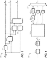
- Fig. 3 is a generalized block diagram of a parametric encoding section 300 according to an example embodiment.
- the parametric encoding section 300 is configured to encode an N -channel audio signal X as a single-channel downmix signal Y and metadata suitable for parametric reconstruction of the audio signal X according to equation (2).
- the parametric encoding section 300 comprises a downmix section 301, which receives the audio signal X and computes, according to a predefined rule, the single-channel downmix signal Y as a linear mapping of the audio signal X.
- the downmix section 301 computes the downmix signal Y according to equation (1), wherein the downmix matrix D is predefined and corresponds to the predefined rule.
- a first analyzing section 302 determines a set of dry upmix coefficients, represented by the dry upmix matrix C, in order to define a linear mapping of the downmix signal Y approximating the audio signal X.
- This linear mapping of the downmix signal Y is denoted by CY in equation (2).
- N dry upmix coefficients C are determined according to equation (4) such that the linear mapping CY of the downmix signal Y corresponds to a minimum mean square approximation of the audio signal X.
- a second analyzing section 303 determines an intermediate matrix H R based on a difference between the covariance matrix of the audio signal X as received and the covariance matrix of the audio signal as approximated by the linear mapping CY of the downmix signal Y .
- the covariance matrices are computed by first and second processing sections 304, 305, respectively, and are then provided to the second analyzing section 303.
- the intermediate matrix H R is determined according to above described approach b to solving equation (10), leading to an intermediate matrix H R which is symmetric.
- the intermediate matrix H R when multiplied by a predefined matrix V, defines, via a set of wet upmix parameters P, a linear mapping PZ of a decorrelated signal Z as part of parametric reconstruction of the audio signal X at a decoder side.
- the parametric encoding section 300 outputs the downmix signal Y together with dry upmix parameters C and wet upmix parameters P ⁇ .
- N - 1 of the N dry upmix coefficients C are the dry upmix parameters C ⁇ , and the remaining one dry upmix coefficient is derivable from the dry upmix parameters C ⁇ via equation (7) if the predefined downmix matrix D is known.
- the intermediate matrix H R belongs to the class of symmetric matrices, it is uniquely defined by N(N - 1)/2 of its ( N - 1) 2 elements. In the present example embodiment, N(N - 1)/2 of the elements of the intermediate matrix H R are therefore wet upmix parameters P ⁇ from which the rest of the intermediate matrix H R is derivable knowing that it is symmetric.
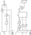
- Fig. 4 is a generalized block diagram of an audio encoding system 400 according to an example embodiment, comprising the parametric encoding section 300 described with reference to Fig. 3 .
- audio content e.g. recorded by one or more acoustic transducers 401, or generated by audio authoring equipment 401, is provided in the form of the N -channel audio signal X.
- a quadrature mirror filter (QMF) analysis section 402 transforms the audio signal X, time segment by time segment, into a QMF domain for processing by the parametric encoding section 300 of the audio signal X in the form of time/frequency tiles.
- QMF quadrature mirror filter
- the downmix signal Y output by the parametric encoding section 300 is transformed back from the QMF domain by a QMF synthesis section 403 and is transformed into a modified discrete cosine transform (MDCT) domain by a transform section 404.
- Quantization sections 405 and 406 quantize the dry upmix parameters C ⁇ and wet upmix parameters P ⁇ , respectively. For example, uniform quantization with a step size of 0.1 or 0.2 (dimensionless) may be employed, followed by entropy coding in the form of Huffman coding. A coarser quantization with step size 0.2 may for example be employed to save transmission bandwidth, and a finer quantization with step size 0.1 may for example be employed to improve fidelity of the reconstruction on a decoder side.
- the MDCT-transformed downmix signal Y and the quantized dry upmix parameters C ⁇ and wet upmix parameters P ⁇ are then combined into a bitstream B by a multiplexer 407, for transmission to a decoder side.
- the audio encoding system 400 may also comprise a core encoder (not shown in Fig. 4 ) configured to encode the downmix signal Y using a perceptual audio codec, such as Dolby Digital or MPEG AAC, before the downmix signal Y is provided to the multiplexer 407.
- Fig. 1 is a generalized block diagram of a parametric reconstruction section 100, according to an example embodiment, configured to reconstruct the N -channel audio signal X based on a single-channel downmix signal Y and associated dry upmix parameters C ⁇ and wet upmix parameters P ⁇ .
- the parametric reconstruction section 100 is adapted to perform reconstruction according to equation (2), i.e. using dry upmix parameters C and wet upmix parameters P ⁇ .
- dry upmix parameters C ⁇ and wet upmix parameters P ⁇ are received from which the dry upmix parameters C ⁇ and wet upmix parameters P are derivable.
- the channels of the decorrelated signal Z are derived by processing the downmix signal Y, including applying respective all-pass filters to the downmix signal Y, so as to provide channels that are uncorrelated to the downmix signal Y , and with audio content which is spectrally similar to and also perceived as similar to that of the downmix signal Y by a listener.
- the ( N - 1)-channel decorrelated signal Z serves to increase the dimensionality of the reconstructed version X ⁇ of N -channel audio signal X, as perceived by a listener.
- the channels of the decorrelated signal Z have at least approximately the same spectra as that of the single-channel downmix signal Y and form, together with the single-channel downmix signal Y, N at least approximately mutually uncorrelated channels.
- a dry upmix section 102 receives the dry upmix parameters C ⁇ and the downmix signal Y .
- the dry upmix parameters C ⁇ coincide with the first N - 1 of the N dry upmix coefficients C, and the remaining dry upmix coefficient is determined based on a predefined relation between the dry upmix coefficients C given by equation (7).
- the dry upmix section 102 outputs a dry upmix signal computed by mapping the downmix signal Y linearly in accordance with the set of dry upmix coefficients C, and denoted by CY in equation (2).
- a wet upmix section 103 receives the wet upmix parameters P ⁇ and the decorrelated signal Z.
- the wet upmix parameters P are N ( N - 1)/2 elements of the intermediate matrix H R determined at the encoder side according to equation (10).
- the wet upmix section 103 populates the remaining elements of the intermediate matrix H R knowing that the intermediate matrix H R belongs to a predefined matrix class, i.e. that it is symmetric, and exploiting the corresponding relationships between the elements of the matrix.
- the N(N - 1) wet upmix coefficients P are derived from the received N(N - 1)/2 independently assignable wet upmix parameters P ⁇ .
- the wet upmix section 103 outputs a wet upmix signal computed by mapping the decorrelated signal Z linearly in accordance with the set of wet upmix coefficients P, and denoted by PZ in equation (2).
- a combining section 104 receives the dry upmix signal CY and the wet upmix signal PZ and combines these signals to obtain a first multidimensional reconstructed signal X ⁇ corresponding to the N -channel audio signal X to be reconstructed.
- the combining section 104 obtains the respective channels of the reconstructed signal X ⁇ by combining the audio content of the respective channels of the dry upmix signal CY with the respective channels of the wet upmix signal PZ, according to equation (2).
- Fig. 2 is a generalized block diagram of an audio decoding system 200 according to an example embodiment.
- the audio decoding system 200 comprises the parametric reconstruction section 100 described with reference to Fig. 1 .
- a receiving section 201 e.g. including a demultiplexer, receives the bitstream B transmitted from the audio encoding system 400 described with reference to Fig. 4 , and extracts the downmix signal Y and the associated dry upmix parameters C ⁇ and wet upmix parameters P ⁇ from the bitstream B.
- the audio decoding system 200 may comprise a core decoder (not shown in Fig.
- a transform section 202 transforms the downmix signal Y by performing inverse MDCT and a QMF analysis section 203 transforms the downmix signal Y into a QMF domain for processing by the parametric reconstruction section 100 of the downmix signal Y in the form of time/frequency tiles.
- Dequantization sections 204 and 205 dequantize the dry upmix parameters C and wet upmix parameters P , e.g., from an entropy coded format, before supplying them to the parametric reconstruction section 100. As described with reference to Fig. 4 , quantization may have been performed with one of two different step sizes, e.g. 0.1 or 0.2.
- the actual step size employed may be predefined, or may be signaled to the audio decoding system 200 from the encoder side, e.g. via the bitstream B.
- the dry upmix coefficients C and the wet upmix coefficients P may be derived from the dry upmix parameters C ⁇ and wet upmix parameters P ⁇ , respectively, already in the respective dequantization sections 204 and 205, which may optionally be regarded as part of the dry upmix section 102 and the wet upmix section 103, respectively.
- the reconstructed audio signal X ⁇ output by the parametric reconstruction section 100 is transformed back from the QMF domain by a QMF synthesis section 206 before being provided as output of the audio decoding system 200 for playback on a multispeaker system 207.
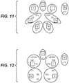
- Figs. 5-11 illustrate alternative ways to represent an 11.1 channel audio signal by means of downmix channels, according to example embodiments.
- the 11.1 channel audio signal comprises the channels: left (L), right (R), center (C), low-frequency effects (LFE), left side (LS), right side (RS), left back (LB), right back (RB), top front left (TFL), top front right (TFR), top back left (TBL) and top back right (TBR), which are indicated in Figures 5-11 by uppercase letters.
- the alternative ways to represent the 11.1 channel audio signal correspond to alternative partitions of the channels into sets of channels, each set being represented by a single downmix signal, and optionally by associated wet and dry upmix parameters. Encoding of each of the sets of channels into its respective single-channel downmix signal (and metadata) may be performed independently and in parallel. Similarly, reconstruction of the respective sets of channels from their respective single-channel downmix signals may be performed independently and in parallel.
- none of the reconstructed channels may comprise contributions from more than one downmix channel and any decorrelated signals derived from that single downmix signal, i.e. contributions from multiple downmix channels are not combined/mixed during parametric reconstruction.
- the channels LS, TBL and LB form a group 501 of channels represented by the single downmix channel ls (and its associated metadata).
- N 3 to represent the three audio channels LS, TBL and LB by the single downmix channel ls and associated dry and wet upmix parameters.
- the channels RS, TBR and RB form a group 502 of channels represented by the single downmix channel rs, and another instance of the parametric encoding section 300 may be employed in parallel with the first encoding section to represent the three channels RS, TBR and RB by the single downmix channel rs and associated dry and wet upmix parameters.
- Another instance of the parametric reconstruction section 100 may be employed in parallel with the first parametric reconstruction section to reconstruct the three channels RS, TBR and RB from the downmix signal rs and the associated dry and wet upmix parameters.
- Another group 504 of channels comprises only a single channel LFE represented by a downmix channel lfe.
- the downmix channel lfe may be the channel LFE itself, optionally transformed into an MDCT domain and/or encoded using a perceptual audio codec.
- the total number of downmix channels employed in Figs. 5-11 to represent the 11.1 channel audio signal varies.
- the example illustrated in Fig. 5 employs 6 downmix channels while the example in Fig. 7 employs 10 downmix channels.
- Different downmix configurations may be suitable for different situations, e.g. depending on available bandwidth for transmission of the downmix signals and associated upmix parameter, and/or requirements on how faithful the reconstruction of the 11.1 channel audio signal should be.
- the audio encoding system 400 described with reference to Fig. 4 may comprise a plurality of parametric encoding sections, including the parametric encoding section 300 described with reference to Fig. 3 .
- the audio encoding system 400 may comprise a control section (not shown in Fig. 4 ) configured to determine/select a coding format for the 11.1-channel audio signal, from a collection for coding formats corresponding to the respective partitions of the 11.1 channel audio signal illustrated in Figs. 5-11 .
- the coding format further corresponds to a set of predefined rules (at least some of which may coincide) for computing the respective downmix channels, a set of predefined matrix classes (at least some of which may coincide) for intermediate matrices H R and a set of predefined matrices V (at least some of which may coincide) for obtaining wet upmix coefficients associated with at least some of the respective sets of channels based on respective associated wet upmix parameters.
- the audio encoding system is configured to encode the 11.1 channel audio signal using a subset of the plurality of encoding sections appropriate to the determined coding format. If, for example, the determined coding format corresponds to the partition of the 11.1 channels illustrated in Fig.
- the encoding system may employ 2 encoding sections configured for representing respective sets of 3 channels by respective single downmix channels, 2 encoding sections configured for representing respective sets of 2 channels by respective single downmix channels, and 2 encoding sections configured for representing respective single channel as respective single downmix channels. All the downmix signals and the associated wet and dry upmix parameters may be encoded in the same bitstream B, for transmittal to a decoder side. It is to be noted that the compact format of the metadata accompanying the downmix channels, i.e. the wet upmix parameters and the wet upmix parameters, may be employed by some of the encoding sections, while in at least some example embodiments, other metadata formats may be employed.
- some of the encoding sections may output the full number of the wet and dry upmix coefficients instead of the wet and dry upmix parameters.
- some channels are encoded for reconstruction employing fewer than N - 1 decorrelated channels (or even no decorrelation at all), and where metadata for parametric reconstruction may therefore take a different form.
- the audio decoding system 200 described with reference to Fig. 2 may comprise a corresponding plurality of reconstruction sections, including the parametric reconstruction section 100 described with reference to Fig. 1 , for reconstructing the respective sets of channels of the 11.1 channel audio signal represented by the respective downmix signals.
- the audio decoding system 200 may comprise a control section (not shown in Fig. 2 ) configured to receive signaling from the encoder side indicating the determined coding format, and the audio decoding system 200 may employ an appropriate subset of the plurality of reconstruction sections for reconstructing the 11.1 channel audio signal from the received downmix signals and associated dry and wet upmix parameters.
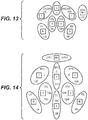
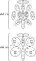
- Figs. 12-13 illustrate alternative ways to represent a 13.1 channel audio signal by means of downmix channels, according to example embodiments.
- the 13. 1 channel audio signal includes the channels: left screen (LSCRN), left wide (LW), right screen (RSCRN), right wide (RW), center (C), low-frequency effects (LFE), left side (LS), right side (RS), left back (LB), right back (RB), top front left (TFL), top front right (TFR), top back left (TBL) and top back right (TBR).
- Encoding of the respective groups of channels as the respective downmix channels may be performed by respective encoding sections operating independently in parallel, as described above with reference to Figs. 5-11 .
- reconstruction of the respective groups of channels based on the respective downmix channels and associated upmix parameters may be performed by respective reconstruction sections operating independently in parallel.
- Figs. 14-16 illustrate alternative ways to represent a 22.2 channel audio signal by means of downmix signals, according to example embodiments.
- the 22. 2 channel audio signal includes the channels: low-frequency effects 1 (LFE1), low-frequency effects 2 (LFE2), bottom front center (BFC), center (C), top front center (TFC), left wide (LW), bottom front left (BFL), left (L), top front left (TFL), top side left (TSL), top back left (TBL), left side (LS), left back (LB), top center (TC), top back center (TBC), center back (CB), bottom front right (BFR), right (R), right wide (RW), top front right (TFR), top side right (TSR), top back right (TBR), right side (RS), and right back (RB).
- LFE1 low-frequency effects 1
- LFE2 low-frequency effects 2
- BFC bottom front center
- C top front center
- TFC left wide
- TFC top front left
- TBL top back left
- the partition of the 22.2 channel audio signal illustrated in Fig.16 includes a group 1601 of channels including four channels.
- the devices and methods disclosed hereinabove may be implemented as software, firmware, hardware or a combination thereof.
- the division of tasks between functional units referred to in the above description does not necessarily correspond to the division into physical units; to the contrary, one physical component may have multiple functionalities, and one task may be carried out by several physical components in cooperation.
- Certain components or all components may be implemented as software executed by a digital signal processor or microprocessor, or be implemented as hardware or as an application-specific integrated circuit.
- Such software may be distributed on computer readable media, which may comprise computer storage media (or non-transitory media) and communication media (or transitory media).
- Computer storage media includes both volatile and nonvolatile, removable and non-removable media implemented in any method or technology for storage of information such as computer readable instructions, data structures, program modules or other data.
- Computer storage media includes, but is not limited to, RAM, ROM, EEPROM, flash memory or other memory technology, CD-ROM, digital versatile disks (DVD) or other optical disk storage, magnetic cassettes, magnetic tape, magnetic disk storage or other magnetic storage devices, or any other medium which can be used to store the desired information and which can be accessed by a computer.
- communication media typically embodies computer readable instructions, data structures, program modules or other data in a modulated data signal such as a carrier wave or other transport mechanism and includes any information delivery media.
Landscapes
- Engineering & Computer Science (AREA)
- Physics & Mathematics (AREA)
- Signal Processing (AREA)
- Acoustics & Sound (AREA)
- Computational Linguistics (AREA)
- Health & Medical Sciences (AREA)
- Audiology, Speech & Language Pathology (AREA)
- Human Computer Interaction (AREA)
- Multimedia (AREA)
- Mathematical Physics (AREA)
- Spectroscopy & Molecular Physics (AREA)
- Stereophonic System (AREA)
Claims (15)
- Verfahren zum Rekonstruieren eines Audiosignals (X ) mit N Kanälen, wobei N≥3 ist, wobei das Verfahren Folgendes umfasst:Empfangen eines Einzelkanal-Downmix-Signals (Y) zusammen mit assoziierten Trocken- und Nass-Upmix-Parametern (C̃,P̃);Berechnen eines Trocken-Upmix-Signals als eine lineare Abbildung des Downmix-Signals, wobei eine Menge von Trocken-Upmix-Koeffizienten (C) am Downmix-Signal angewendet wird;Erzeugen eines dekorrelierten Signals (Z) basierend auf dem Downmix-Signal, wobei das dekorrelierte Signal N-1 Kanäle aufweist;Berechnen eines Nass-Upmix-Signals als eine lineare Abbildung der N -1 Kanäle des dekorrelierten Signals, wobei eine Menge von Nass-Upmix-Koeffizienten (P) an den N -1 Kanälen des dekorrelierten Signals angewendet wird; undKombinieren des Trocken- und des Nass-Upmix-Signals, um ein mehrdimensionales rekonstruiertes Signal (X̂) zu erhalten, das dem zu rekonstruierenden Audiosignal mit N Kanälen entspricht,wobei das Verfahren ferner Folgendes umfasst:Bestimmen der Menge von Trocken-Upmix-Koeffizienten basierend auf den empfangenen Trocken-Upmix-Parametern;Befüllen einer Zwischenmatrix, die mehr Elemente als die Anzahl von empfangenen Nass-Upmix-Parametern aufweist, basierend auf den empfangenen Nass-Upmix-Parametern und unter der Kenntnis, dass die Zwischenmatrix zu einer vordefinierten Matrixklasse gehört, wobei bekannte Eigenschaften aller Matrizen in der vordefinierten Matrixklasse bekannte Beziehungen zwischen vordefinierten Matrixelementen oder vordefinierte Matrixelemente, die Null sind, beinhalten; undErhalten der Menge von Nass-Upmix-Koeffizienten durch Multiplizieren der Zwischenmatrix mit einer vordefinierten Matrix, wobei die Menge von Nass-Upmix-Koeffizienten der Matrix entspricht, die aus der Multiplikation resultiert, und mehr Koeffizienten als die Anzahl von Elementen in der Zwischenmatrix beinhaltet.
- Verfahren nach Anspruch 1, wobei das Empfangen der Nass-Upmix-Parameter Empfangen von N(N -1)/2 Nass-Upmix-Parametern beinhaltet, wobei das Befüllen der Zwischenmatrix Erhalten von Werten für (N -1)2 Matrixelemente basierend auf den empfangenen N(N-1)/2 Nass-Upmix-Parametern und unter der Kenntnis, dass die Zwischenmatrix zu der vordefinierten Matrixklasse gehört, beinhaltet, wobei die vordefinierte Matrix N(N-1) Elemente beinhaltet und wobei die Menge von Nass-Upmix-Koeffizienten N(N-1) Koeffizienten beinhaltet,
und optional, wobei das Befüllen der Zwischenmatrix Einsetzen der empfangenen Nass-Upmix-Parameter als Elemente in der Zwischenmatrix beinhaltet. - Verfahren nach einem der vorangegangenen Ansprüche, wobei das Empfangen der Trocken-Upmix-Parameter Empfangen von N-1 Trocken-Upmix-Parametern beinhaltet, wobei die Menge von Trocken-Upmix-Koeffizienten N Koeffizienten beinhaltet und wobei die Menge von Trocken-Upmix-Koeffizienten basierend auf den empfangenen N-1 Trocken-Upmix-Parametern und basierend auf einer vordefinierten Beziehung zwischen den Koeffizienten in der Menge von Trocken-Upmix-Koeffizienten bestimmt wird,
und optional, wobei die vordefinierte Matrixklasse eine der folgenden ist:untere oder obere Dreiecksmatrizen, wobei bekannte Eigenschaften aller Matrizen in der Klasse vordefinierte Matrixelemente, die Null sind, beinhalten;symmetrische Matrizen, wobei bekannte Eigenschaften aller Matrizen in der Klasse vordefinierte Matrixelemente, die gleich sind, beinhalten; undProdukte einer orthogonalen Matrix und einer Diagonalmatrix, wobei bekannte Eigenschaften aller Matrizen in der Klasse bekannte Beziehungen zwischen vordefinierten Matrixelementen beinhalten. - Verfahren nach einem der vorangegangenen Ansprüche, wobei das Downmix-Signal gemäß einer vordefinierten Regel als eine lineare Abbildung des zu rekonstruierenden Audiosignals mit N Kanälen erhalten werden kann, wobei die vordefinierte Regel eine vordefinierte Downmix-Operation definiert und wobei die vordefinierte Matrix auf Vektoren basiert, die den Kernel-Raum der vordefinierten Downmix-Operation umspannen.
- Verfahren nach einem der vorangegangenen Ansprüche, wobei das Empfangen des Einzelkanal-Downmix-Signals zusammen mit assoziierten Trocken- und Nass-Upmix-Parametern Empfangen eines Zeitsegments oder einer Zeit/Frequenz-Kachel des Downmix-Signals zusammen mit assoziierten Trocken- und Nass-Upmix-Parametern beinhaltet und wobei das mehrdimensionale rekonstruierte Signal einem Zeitsegment oder einer Zeit/Frequenz-Kachel des zu rekonstruierenden Audiosignals mit N Kanälen entspricht.
- Audiodecodierungssystem (200), das einen ersten parametrischen Rekonstruktionsabschnitt (100) umfasst, der konfiguriert ist zum Rekonstruieren eines Audiosignals (X) mit N Kanälen basierend auf einem ersten Einzelkanal-Downmix-Signal (Y) und assoziierten Trocken- und Nass-Upmix-Parametern (C̃,P̃), wobei N≥3 ist, wobei der erste parametrische Rekonstruktionsabschnitt Folgendes umfasst:einen ersten Dekorrelationsabschnitt (101), der konfiguriert ist zum Empfangen des ersten Downmix-Signals und zum Ausgeben, basierend darauf, eines ersten dekorrelierten Signals (Z) mit N-1 Kanälen;einen ersten Trocken-Upmix-Abschnitt (102), der konfiguriert ist zumEmpfangen der Trocken-Upmix-Parameter (C̃) und des Downmix-Signals,Bestimmen einer ersten Menge von Trocken-Upmix-Koeffizienten (C) basierend auf den Trocken-Upmix-Parametern undAusgeben eines ersten Trocken-Upmix-Signals, das durch lineares Abbilden des ersten Downmix-Signals gemäß der ersten Menge von Trocken-Upmix-Koeffizienten berechnet wird;einen ersten Nass-Upmix-Abschnitt (103), der konfiguriert ist zumEmpfangen der Nass-Upmix-Parameter (P̃) und des ersten dekorrelierten Signals,Befüllen einer ersten Zwischenmatrix, die mehr Elemente als die Anzahl von empfangenen Nass-Upmix-Parametern aufweist, basierend auf den empfangenen Nass-Upmix-Parametern und unter der Kenntnis, dass die erste Zwischenmatrix zu einer ersten vordefinierten Matrixklasse gehört, wobei bekannte Eigenschaften aller Matrizen in der ersten vordefinierten Matrixklasse bekannte Beziehungen zwischen vordefinierten Matrixelementen odervordefinierte Matrixelemente, die Null sind, beinhalten,Erhalten einer ersten Menge von Nass-Upmix-Koeffizienten (P) durch Multiplizieren der ersten Zwischenmatrix mit einer ersten vordefinierten Matrix, wobei die erste Menge von Nass-Upmix-Koeffizienten der Matrix entspricht, die aus der Multiplikation resultiert, und mehr Koeffizienten als die Anzahl von Elementen in der ersten Zwischenmatrix beinhaltet, undAusgeben eines ersten Nass-Upmix-Signals, das durch lineares Abbilden der N-1 Kanäle des ersten dekorrelierten Signals gemäß der ersten Menge von Nass-Upmix-Koeffizienten berechnet wird; undeinen ersten Kombinationsabschnitt (104), der konfiguriert ist zum Empfangen des ersten Trocken-Upmix-Signals und des ersten Nass-Upmix-Signals und zum Kombinieren dieser Signale, um ein erstes mehrdimensionales rekonstruiertes Signal (X̂) zu erhalten, das dem zu rekonstruierenden Audiosignal mit N Kanälen entspricht.
- Audiodecodierungssystem nach Anspruch 6, das ferner einen zweiten parametrischen Rekonstruktionsabschnitt umfasst, der unabhängig vom ersten parametrischen Rekonstruktionsabschnitt betreibbar ist und konfiguriert ist zum Rekonstruieren eines Audiosignals mit N2 Kanälen basierend auf einem zweiten Einzelkanal-Downmix-Signal und assoziierten Trocken- und Nass-Upmix-Parametern, wobei N 2≥2 ist, wobei der zweite parametrische Rekonstruktionsabschnitt einen zweiten Dekorrelationsabschnitt, einen zweiten Trocken-Upmix-Abschnitt, einen zweiten Nass-Upmix-Abschnitt und einen zweiten Kombinationsabschnitt umfasst, wobei die Abschnitte des zweiten parametrischen Rekonstruktionsabschnitts analog zu den entsprechenden Abschnitten des ersten parametrischen Rekonstruktionsabschnitts konfiguriert sind, wobei der zweite Nass-Upmix-Abschnitt konfiguriert ist zum Einsetzen einer zweiten Zwischenmatrix, die zu einer zweiten vordefinierten Matrixklasse gehört, und einer zweiten vordefinierten Matrix.
- Audiodecodierungssystem nach Anspruch 6 oder 7, wobei das Audiodecodierungssystem dazu ausgelegt ist, ein Mehrkanal-Audiosignal basierend auf mehreren Downmix-Kanälen und assoziierten Trocken- und Nass-Upmix-Parametern zu rekonstruieren, wobei das Audiodecodierungssystem Folgendes umfasst:mehrere Rekonstruktionsabschnitte, einschließlich parametrischen Rekonstruktionsabschnitten, die betreibbar sind, jeweilige Mengen von Audiosignalkanälen basierend auf jeweiligen Downmix-Kanälen und jeweiligen assoziierten Trocken- und Nass-Upmix-Parametern unabhängig zu rekonstruieren; undeinen Steuerabschnitt, der konfiguriert ist zum Empfangen einer Signalisierung, die ein Codierungsformat des Mehrkanal-Audiosignals angibt, das einer Partitionierung der Kanäle des Mehrkanal-Audiosignals in Mengen (501-504) von Kanälen entspricht, die durch die jeweiligen Downmix-Kanäle und, für zumindest manche der Downmix-Kanäle, durch jeweilige assoziierte Trocken- und Nass-Upmix-Parameter repräsentiert werden, wobei das Codierungsformat ferner einer Menge von vordefinierten Matrizen entspricht, um Nass-Upmix-Koeffizienten, die mit zumindest manchen der jeweiligen Mengen von Kanälen assoziiert sind, basierend auf den jeweiligen assoziierten Nass-Upmix-Parametern zu erhalten,wobei das Decodierungssystem konfiguriert ist zum Rekonstruieren des Mehrkanal-Audiosignals unter Verwendung einer ersten Teilmenge der mehreren Rekonstruktionsabschnitte als Reaktion auf die empfangene Signalisierung, die ein erstes Codierungsformat angibt, wobei das Decodierungssystem konfiguriert ist zum Rekonstruieren des Mehrkanal-Audiosignals unter Verwendung einer zweiten Teilmenge der mehreren Rekonstruktionsabschnitte als Reaktion auf die empfangene Signalisierung, die ein zweites Codierungsformat angibt, und wobei die erste und/oder die zweite Teilmenge der Rekonstruktionsabschnitte den ersten parametrischen Rekonstruktionsabschnitt umfasst bzw. umfassen.
- Audiodecodierungssystem nach Anspruch 8, wobei die mehreren Rekonstruktionsabschnitte einen Einzelkanal-Rekonstruktionsabschnitt beinhalten, der betreibbar ist, einen einzelnen Audiokanal basierend auf einem Downmix-Kanal, in dem nicht mehr als ein einzelner Audiokanal codiert worden ist, unabhängig zu rekonstruieren und wobei die erste und/oder die zweite Teilmenge der Rekonstruktionsabschnitte den Einzelkanal-Rekonstruktionsabschnitt umfasst bzw. umfassen, und/oder
wobei das erste Codierungsformat einer Rekonstruktion des Mehrkanal-Audiosignals aus einer geringeren Anzahl von Downmix-Kanälen als das zweite Codierungsformat entspricht. - Verfahren zum Codieren eines Audiosignals (X) mit N Kanälen als ein Einzelkanal-Downmix-Signal (Y) und Metadaten, die sich für eine parametrische Rekonstruktion des Audiosignals aus dem Downmix-Signal und einem dekorrelierten Signal (Z), das basierend auf dem Downmix-Signal bestimmt wird, eignen, wobei N≥3 ist und wobei das dekorrelierte Signal N-1 Kanäle aufweist, wobei das Verfahren Folgendes umfasst:Empfangen des Audiosignals;Berechnen, gemäß einer vordefinierten Regel, des Einzelkanal-Downmix-Signals als eine lineare Abbildung des Audiosignals;Bestimmen einer Menge von Trocken-Upmix-Koeffizienten (C), um eine lineare Abbildung des Downmix-Signals zu definieren, die das Audiosignal approximiert;Bestimmen einer Zwischenmatrix basierend auf einer Differenz zwischen einer Kovarianz des wie empfangenen Audiosignals und einer Kovarianz des wie durch die lineare Abbildung des Downmix-Signals approximierten Audiosignals, wobei die Zwischenmatrix, wenn sie mit einer vordefinierten Matrix multipliziert wird, einer Menge von Nass-Upmix-Koeffizienten (P) entspricht, die eine lineare Abbildung der N-1 Kanäle des dekorrelierten Signals als Teil einer parametrischen Rekonstruktion des Audiosignals definieren, wobei die Menge von Nass-Upmix-Koeffizienten mehr Koeffizienten als die Anzahl von Elementen in der Zwischenmatrix beinhaltet; undAusgeben des Downmix-Signals zusammen mit Trocken-Upmix-Parametern (C̃), aus denen die Menge von Trocken-Upmix-Koeffizienten hergeleitet werden kann, und Nass-Upmix-Parametern (P̃), wobei die Zwischenmatrix mehr Elemente als die Anzahl von ausgegebenen Nass-Upmix-Parametern aufweist und wobei die Zwischenmatrix eindeutig durch die ausgegebenen Nass-Upmix-Parameter definiert wird, sofern die Zwischenmatrix zu einer vordefinierten Matrixklasse gehört, wobei bekannte Eigenschaften aller Matrizen in der vordefinierten Matrixklasse bekannte Beziehungen zwischen vordefinierten Matrixelementen oder vordefinierte Matrixelemente, die Null sind, beinhalten.
- Verfahren nach Anspruch 10, wobei das Bestimmen der Zwischenmatrix ein derartiges Bestimmen der Zwischenmatrix beinhaltet, dass eine Kovarianz des durch die lineare Abbildung des dekorrelierten Signals, die durch die Menge von Nass-Upmix-Koeffizienten definiert wird, erhaltenen Signals die Differenz zwischen der Kovarianz des wie empfangenen Audiosignals und der Kovarianz des wie durch die lineare Abbildung des Downmix-Signals approximierten Audiosignals approximiert, und/oder wobei das Ausgeben der Nass-Upmix-Parameter Ausgeben von nicht mehr als N(N-1)/2 Nass-Upmix-Parametern beinhaltet, wobei die Zwischenmatrix (N-1)2 Matrixelemente aufweist und eindeutig durch die ausgegebenen Nass-Upmix-Parameter definiert wird, sofern die Zwischenmatrix zu der vordefinierten Matrixklasse gehört, und wobei die Menge von Nass-Upmix-Koeffizienten N(N-1) Koeffizienten beinhaltet, und/oder
wobei die Menge von Trocken-Upmix-Koeffizienten N Koeffizienten beinhaltet und wobei das Ausgeben der Trocken-Upmix-Parameter Ausgeben von nicht mehr als N-1 Trocken-Upmix-Parametern beinhaltet, wobei die Menge von Trocken-Upmix-Koeffizienten aus den N-1 Trocken-Upmix-Parametern unter Verwendung der vordefinierten Regel hergeleitet werden kann, und/oder
wobei die bestimmte Menge von Trocken-Upmix-Koeffizienten eine lineare Abbildung des Downmix-Signals definiert, die einer Minimalapproximation des mittleren quadratischen Fehlers des Audiosignals entspricht. - Audiocodierungssystem (400), das einen parametrischen Codierungsabschnitt (300) umfasst, der konfiguriert ist zum Codieren eines Audiosignals (X) mit N Kanälen als ein Einzelkanal-Downmix-Signal (Y) und Metadaten, die sich für eine parametrische Rekonstruktion des Audiosignals aus dem Downmix-Signal und einem dekorrelierten Signal (Z), das basierend auf dem Downmix-Signal bestimmt wird, eignen, wobei N≥3 ist und wobei das dekorrelierte Signal N-1 Kanäle aufweist, wobei der parametrische Codierungsabschnitt Folgendes umfasst:einen Downmix-Abschnitt (301), der konfiguriert ist zum Empfangen des Audiosignals und zum Berechnen, gemäß einer vordefinierten Regel, des Einzelkanal-Downmix-Signals als eine lineare Abbildung des Audiosignals;einen ersten Analyseabschnitt (302), der konfiguriert ist zum Bestimmen einer Menge von Trocken-Upmix-Koeffizienten (C), um eine lineare Abbildung des Downmix-Signals zu definieren, die das Audiosignal approximiert; undeinen zweiten Analyseabschnitt (303), der konfiguriert ist zum Bestimmen einer Zwischenmatrix basierend auf einer Differenz zwischen einer Kovarianz des wie empfangenen Audiosignals und einer Kovarianz des wie durch die lineare Abbildung des Downmix-Signals approximierten Audiosignals, wobei die Zwischenmatrix, wenn sie mit einer vordefinierten Matrix multipliziert wird, einer Menge von Nass-Upmix-Koeffizienten (P) entspricht, die eine lineare Abbildung der N-1 Kanäle des dekorrelierten Signals als Teil einer parametrischen Rekonstruktion des Audiosignals definieren, wobei die Menge von Nass-Upmix-Koeffizienten mehr Koeffizienten als die Anzahl von Elementen in der Zwischenmatrix beinhaltet,wobei der parametrische Codierungsabschnitt konfiguriert ist zum Ausgeben des Downmix-Signals zusammen mit Trocken-Upmix-Parametern (C̃), aus denen die Menge von Trocken-Upmix-Koeffizienten hergeleitet werden kann, und Nass-Upmix-Parametern (P̃), wobei die Zwischenmatrix mehr Elemente als die Anzahl von ausgegebenen Nass-Upmix-Parametern aufweist und wobei die Zwischenmatrix eindeutig durch die ausgegebenen Nass-Upmix-Parameter definiert wird, sofern die Zwischenmatrix zu einer vordefinierten Matrixklasse gehört, wobei bekannte Eigenschaften aller Matrizen in der vordefinierten Matrixklasse bekannte Beziehungen zwischen vordefinierten Matrixelementen oder vordefinierte Matrixelemente, die Null sind, beinhalten.
- Audiocodierungssystem nach Anspruch 12, wobei das Audiocodierungssystem dazu ausgelegt ist, eine Repräsentation eines Mehrkanal-Audiosignals in Form mehrerer Downmix-Kanäle und assoziierter Trocken- und Nass-Upmix-Parameter bereitzustellen, wobei das Audiocodierungssystem Folgendes umfasst:mehrere Codierungsabschnitte, einschließlich parametrischer Codierungsabschnitte, die betreibbar sind, jeweilige Downmix-Kanäle und jeweilige assoziierte Upmix-Parameter basierend auf jeweiligen Mengen von Audiosignalkanälen unabhängig zu berechnen;einen Steuerabschnitt, der konfiguriert ist zum Bestimmen eines Codierungsformats für das Mehrkanal-Audiosignal, das einer Partitionierung der Kanäle des Mehrkanal-Audiosignals in Mengen (501-504) von Kanälen entspricht, die durch die jeweiligen Downmix-Kanäle und, für zumindest manche der Downmix-Kanäle, durch jeweilige assoziierte Upmix-Parameter repräsentiert werden sollen, wobei das Codierungsformat ferner einer Menge von vordefinierten Regeln entspricht, um zumindest manche der jeweiligen Downmix-Kanäle zu berechnen,wobei das Audiocodierungssystem konfiguriert ist zum Codieren des Mehrkanal-Audiosignals unter Verwendung einer ersten Teilmenge der mehreren Codierungsabschnitte als Reaktion darauf, dass das bestimmte Codierungsformat ein erstes Codierungsformat ist, wobei das Audiocodierungssystem konfiguriert ist zum Codieren des Mehrkanal-Audiosignals unter Verwendung einer zweiten Teilmenge der mehreren Codierungsabschnitte als Reaktion darauf, dass das bestimmte Codierungsformat ein zweites Codierungsformat ist, und wobei die erste und/oder die zweite Teilmenge der Codierungsabschnitte den ersten parametrischen Codierungsabschnitt umfasst bzw. umfassen.
- Audiocodierungssystem nach Anspruch 13, wobei die mehreren Codierungsabschnitte einen Einzelkanal-Codierungsabschnitt beinhalten, der betreibbar ist, nicht mehr als einen einzelnen Audiokanal in einem Downmix-Kanal unabhängig zu codieren, und wobei die erste und/oder die zweite Teilmenge der Codierungsabschnitte den Einzelkanal-Codierungsabschnitt umfasst bzw. umfassen.
- Computerprogrammprodukt, das ein computerlesbares Medium mit Anweisungen zum Durchführen des Verfahrens nach einem der Ansprüche 1-5, 10 oder 11 umfasst.
Applications Claiming Priority (4)
| Application Number | Priority Date | Filing Date | Title |
|---|---|---|---|
| US201361893770P | 2013-10-21 | 2013-10-21 | |
| US201461974544P | 2014-04-03 | 2014-04-03 | |
| US201462037693P | 2014-08-15 | 2014-08-15 | |
| PCT/EP2014/072570 WO2015059153A1 (en) | 2013-10-21 | 2014-10-21 | Parametric reconstruction of audio signals |
Publications (2)
| Publication Number | Publication Date |
|---|---|
| EP3061089A1 EP3061089A1 (de) | 2016-08-31 |
| EP3061089B1 true EP3061089B1 (de) | 2018-01-17 |
Family
ID=51845388
Family Applications (1)
| Application Number | Title | Priority Date | Filing Date |
|---|---|---|---|
| EP14792778.4A Active EP3061089B1 (de) | 2013-10-21 | 2014-10-21 | Parametrische rekonstruktion von tonsignalen |
Country Status (9)
| Country | Link |
|---|---|
| US (6) | US9978385B2 (de) |
| EP (1) | EP3061089B1 (de) |
| JP (1) | JP6479786B2 (de) |
| KR (4) | KR20230011480A (de) |
| CN (3) | CN111192592B (de) |
| BR (1) | BR112016008817B1 (de) |
| ES (1) | ES2660778T3 (de) |
| RU (1) | RU2648947C2 (de) |
| WO (1) | WO2015059153A1 (de) |
Families Citing this family (12)
| Publication number | Priority date | Publication date | Assignee | Title |
|---|---|---|---|---|
| JP6201047B2 (ja) | 2013-10-21 | 2017-09-20 | ドルビー・インターナショナル・アーベー | オーディオ信号のパラメトリック再構成のための脱相関器構造 |
| RU2704266C2 (ru) | 2014-10-31 | 2019-10-25 | Долби Интернешнл Аб | Параметрическое кодирование и декодирование многоканальных аудиосигналов |
| TWI587286B (zh) | 2014-10-31 | 2017-06-11 | 杜比國際公司 | 音頻訊號之解碼和編碼的方法及系統、電腦程式產品、與電腦可讀取媒體 |
| US9986363B2 (en) * | 2016-03-03 | 2018-05-29 | Mach 1, Corp. | Applications and format for immersive spatial sound |
| CN106851489A (zh) * | 2017-03-23 | 2017-06-13 | 李业科 | 在小房间摆放多声道音箱的方法 |
| US9820073B1 (en) | 2017-05-10 | 2017-11-14 | Tls Corp. | Extracting a common signal from multiple audio signals |
| SG11202000510VA (en) * | 2017-07-28 | 2020-02-27 | Fraunhofer Ges Forschung | Apparatus for encoding or decoding an encoded multichannel signal using a filling signal generated by a broad band filter |
| JP7107727B2 (ja) * | 2018-04-17 | 2022-07-27 | シャープ株式会社 | 音声処理装置、音声処理方法、プログラム、及び、プログラムの記録媒体 |
| CN111696625A (zh) * | 2020-04-21 | 2020-09-22 | 天津金域医学检验实验室有限公司 | 一种fish室荧光计数系统 |
| CN118414661A (zh) | 2021-12-20 | 2024-07-30 | 杜比国际公司 | Qmf域中的ivas spar滤波器组 |
| WO2024073401A2 (en) * | 2022-09-30 | 2024-04-04 | Sonos, Inc. | Home theatre audio playback with multichannel satellite playback devices |
| WO2024097485A1 (en) | 2022-10-31 | 2024-05-10 | Dolby Laboratories Licensing Corporation | Low bitrate scene-based audio coding |
Family Cites Families (53)
| Publication number | Priority date | Publication date | Assignee | Title |
|---|---|---|---|---|
| US6111958A (en) * | 1997-03-21 | 2000-08-29 | Euphonics, Incorporated | Audio spatial enhancement apparatus and methods |
| MXPA03001852A (es) * | 2000-08-31 | 2003-09-10 | Dolby Lab Licensing Corp | Metodo para aparato para descodificacion de matriz de audio. |
| CA3026283C (en) * | 2001-06-14 | 2019-04-09 | Dolby Laboratories Licensing Corporation | Reconstructing audio signals with multiple decorrelation techniques |
| SE0400998D0 (sv) * | 2004-04-16 | 2004-04-16 | Cooding Technologies Sweden Ab | Method for representing multi-channel audio signals |
| SE0402651D0 (sv) * | 2004-11-02 | 2004-11-02 | Coding Tech Ab | Advanced methods for interpolation and parameter signalling |
| SE0402649D0 (sv) | 2004-11-02 | 2004-11-02 | Coding Tech Ab | Advanced methods of creating orthogonal signals |
| SE0402652D0 (sv) * | 2004-11-02 | 2004-11-02 | Coding Tech Ab | Methods for improved performance of prediction based multi- channel reconstruction |
| US20060165247A1 (en) | 2005-01-24 | 2006-07-27 | Thx, Ltd. | Ambient and direct surround sound system |
| DE102005010057A1 (de) | 2005-03-04 | 2006-09-07 | Fraunhofer-Gesellschaft zur Förderung der angewandten Forschung e.V. | Vorrichtung und Verfahren zum Erzeugen eines codierten Stereo-Signals eines Audiostücks oder Audiodatenstroms |
| KR101271069B1 (ko) * | 2005-03-30 | 2013-06-04 | 돌비 인터네셔널 에이비 | 다중채널 오디오 인코더 및 디코더와, 인코딩 및 디코딩 방법 |
| EP1829424B1 (de) * | 2005-04-15 | 2009-01-21 | Dolby Sweden AB | Zeitliche hüllkurvenformgebung von entkorrelierten signalen |
| US8577686B2 (en) * | 2005-05-26 | 2013-11-05 | Lg Electronics Inc. | Method and apparatus for decoding an audio signal |
| ES2374309T3 (es) * | 2005-07-14 | 2012-02-15 | Koninklijke Philips Electronics N.V. | Decodificación de audio. |
| EP1938311B1 (de) * | 2005-08-30 | 2018-05-02 | LG Electronics Inc. | Vorrichtung zum dekodieren von audiosignalen und verfahren dafür |
| EP1921606B1 (de) * | 2005-09-02 | 2011-10-19 | Panasonic Corporation | Vorrichtung und verfahren zur energieformung |
| KR100888474B1 (ko) * | 2005-11-21 | 2009-03-12 | 삼성전자주식회사 | 멀티채널 오디오 신호의 부호화/복호화 장치 및 방법 |
| JP2007178684A (ja) * | 2005-12-27 | 2007-07-12 | Matsushita Electric Ind Co Ltd | マルチチャンネルオーディオ復号装置 |
| WO2007083959A1 (en) * | 2006-01-19 | 2007-07-26 | Lg Electronics Inc. | Method and apparatus for processing a media signal |
| JP5222279B2 (ja) | 2006-03-28 | 2013-06-26 | フラウンホーファー−ゲゼルシャフト・ツール・フェルデルング・デル・アンゲヴァンテン・フォルシュング・アインゲトラーゲネル・フェライン | マルチチャネルオーディオ再構成における信号整形のための改善された方法 |
| US7965848B2 (en) * | 2006-03-29 | 2011-06-21 | Dolby International Ab | Reduced number of channels decoding |
| US8433583B2 (en) * | 2006-03-29 | 2013-04-30 | Koninklijke Philips International N.V. | Audio decoding |
| JP5113151B2 (ja) | 2006-04-03 | 2013-01-09 | エルジー エレクトロニクス インコーポレイティド | メディア信号処理装置及びその方法 |
| US8041041B1 (en) * | 2006-05-30 | 2011-10-18 | Anyka (Guangzhou) Microelectronics Technology Co., Ltd. | Method and system for providing stereo-channel based multi-channel audio coding |
| WO2007146424A2 (en) | 2006-06-15 | 2007-12-21 | The Force Inc. | Condition-based maintenance system and method |
| US7876904B2 (en) | 2006-07-08 | 2011-01-25 | Nokia Corporation | Dynamic decoding of binaural audio signals |
| MX2009003570A (es) * | 2006-10-16 | 2009-05-28 | Dolby Sweden Ab | Codificacion mejorada y representacion de parametros para codificacion de objetos de mezcla descendente de multicanal. |
| DE102007018032B4 (de) * | 2007-04-17 | 2010-11-11 | Fraunhofer-Gesellschaft zur Förderung der angewandten Forschung e.V. | Erzeugung dekorrelierter Signale |
| RU2439719C2 (ru) * | 2007-04-26 | 2012-01-10 | Долби Свиден АБ | Устройство и способ для синтезирования выходного сигнала |
| EP2082396A1 (de) * | 2007-10-17 | 2009-07-29 | Fraunhofer-Gesellschaft zur Förderung der angewandten Forschung e.V. | Audiokodierung mit downmix |
| KR101629862B1 (ko) * | 2008-05-23 | 2016-06-24 | 코닌클리케 필립스 엔.브이. | 파라메트릭 스테레오 업믹스 장치, 파라메트릭 스테레오 디코더, 파라메트릭 스테레오 다운믹스 장치, 파라메트릭 스테레오 인코더 |
| EP2144229A1 (de) | 2008-07-11 | 2010-01-13 | Fraunhofer-Gesellschaft zur Förderung der angewandten Forschung e.V. | Effiziente Nutzung von Phaseninformationen beim Audio-Codieren und -Decodieren |
| US8346379B2 (en) | 2008-09-25 | 2013-01-01 | Lg Electronics Inc. | Method and an apparatus for processing a signal |
| US8346380B2 (en) | 2008-09-25 | 2013-01-01 | Lg Electronics Inc. | Method and an apparatus for processing a signal |
| US8258849B2 (en) | 2008-09-25 | 2012-09-04 | Lg Electronics Inc. | Method and an apparatus for processing a signal |
| EP2175670A1 (de) * | 2008-10-07 | 2010-04-14 | Fraunhofer-Gesellschaft zur Förderung der angewandten Forschung e.V. | Binaurale Aufbereitung eines Mehrkanal-Audiosignals |
| EP2214161A1 (de) * | 2009-01-28 | 2010-08-04 | Fraunhofer-Gesellschaft zur Förderung der angewandten Forschung e.V. | Vorrichtung, Verfahren und Computerprogramm zur Aufwärtsmischung eines Downmix-Tonsignals |
| EP2214162A1 (de) | 2009-01-28 | 2010-08-04 | Fraunhofer-Gesellschaft zur Förderung der angewandten Forschung e.V. | Aufwärtsmischer, Verfahren und Computerprogramm zur Aufwärtsmischung eines Downmix-Tonsignals |
| US8666752B2 (en) | 2009-03-18 | 2014-03-04 | Samsung Electronics Co., Ltd. | Apparatus and method for encoding and decoding multi-channel signal |
| PL2405425T3 (pl) | 2009-04-08 | 2014-12-31 | Fraunhofer Ges Forschung | Urządzenie, sposób i program komputerowy do realizacji upmixu sygnału audio downmixu z użyciem wygładzania wartości faz |
| US20120039477A1 (en) * | 2009-04-21 | 2012-02-16 | Koninklijke Philips Electronics N.V. | Audio signal synthesizing |
| US8705769B2 (en) | 2009-05-20 | 2014-04-22 | Stmicroelectronics, Inc. | Two-to-three channel upmix for center channel derivation |
| ES2524428T3 (es) * | 2009-06-24 | 2014-12-09 | Fraunhofer-Gesellschaft zur Förderung der angewandten Forschung e.V. | Decodificador de señales de audio, procedimiento para decodificar una señal de audio y programa de computación que utiliza etapas en cascada de procesamiento de objetos de audio |
| JP5758902B2 (ja) * | 2009-10-16 | 2015-08-05 | フラウンホッファー−ゲゼルシャフト ツァ フェルダールング デァ アンゲヴァンテン フォアシュンク エー.ファオ | ダウンミックス信号表現と、ダウンミックス信号表現に関係するパラメトリックサイド情報に基づくアップミックス信号表現の提供に対して、平均値を用いて、1つ以上の調整されたパラメータを提供する装置、方法およびコンピュータプログラム |
| TWI431611B (zh) * | 2009-10-20 | 2014-03-21 | Dolby Int Ab | 用以基於下混信號表示型態提供上混信號表示型態之裝置、用以提供表示多聲道音訊信號的位元串流之裝置、使用失真控制發訊之方法、電腦程式與位元串流 |
| WO2012122397A1 (en) | 2011-03-09 | 2012-09-13 | Srs Labs, Inc. | System for dynamically creating and rendering audio objects |
| CN102446507B (zh) * | 2011-09-27 | 2013-04-17 | 华为技术有限公司 | 一种下混信号生成、还原的方法和装置 |
| WO2013120510A1 (en) * | 2012-02-14 | 2013-08-22 | Huawei Technologies Co., Ltd. | A method and apparatus for performing an adaptive down- and up-mixing of a multi-channel audio signal |
| CN103325383A (zh) * | 2012-03-23 | 2013-09-25 | 杜比实验室特许公司 | 音频处理方法和音频处理设备 |
| WO2013181272A2 (en) | 2012-05-31 | 2013-12-05 | Dts Llc | Object-based audio system using vector base amplitude panning |
| DE102012210525A1 (de) | 2012-06-21 | 2013-12-24 | Robert Bosch Gmbh | Verfahren zur Funktionskontrolle eines Sensors zur Detektion von Teilchen und Sensor zur Detektion von Teilchen |
| US9288603B2 (en) | 2012-07-15 | 2016-03-15 | Qualcomm Incorporated | Systems, methods, apparatus, and computer-readable media for backward-compatible audio coding |
| US9761229B2 (en) | 2012-07-20 | 2017-09-12 | Qualcomm Incorporated | Systems, methods, apparatus, and computer-readable media for audio object clustering |
| EP2830053A1 (de) * | 2013-07-22 | 2015-01-28 | Fraunhofer-Gesellschaft zur Förderung der angewandten Forschung e.V. | Mehrkanaliger Audiodecodierer, mehrkanaliger Audiocodierer, Verfahren und Computerprogramm mit restsignalbasierter Anpassung einer Beteiligung eines dekorrelierten Signals |
-
2014
- 2014-10-21 KR KR1020237000408A patent/KR20230011480A/ko active IP Right Grant
- 2014-10-21 KR KR1020217011678A patent/KR102381216B1/ko active IP Right Grant
- 2014-10-21 KR KR1020167010113A patent/KR102244379B1/ko active IP Right Grant
- 2014-10-21 EP EP14792778.4A patent/EP3061089B1/de active Active
- 2014-10-21 RU RU2016119563A patent/RU2648947C2/ru active
- 2014-10-21 CN CN202010024100.3A patent/CN111192592B/zh active Active
- 2014-10-21 CN CN202010024095.6A patent/CN111179956B/zh active Active
- 2014-10-21 JP JP2016524490A patent/JP6479786B2/ja active Active
- 2014-10-21 US US15/031,130 patent/US9978385B2/en active Active
- 2014-10-21 BR BR112016008817-4A patent/BR112016008817B1/pt active IP Right Grant
- 2014-10-21 ES ES14792778.4T patent/ES2660778T3/es active Active
- 2014-10-21 WO PCT/EP2014/072570 patent/WO2015059153A1/en active Application Filing
- 2014-10-21 KR KR1020227010258A patent/KR102486365B1/ko active IP Right Grant
- 2014-10-21 CN CN201480057568.5A patent/CN105917406B/zh active Active
-
2018
- 2018-05-21 US US15/985,635 patent/US10242685B2/en active Active
-
2019
- 2019-03-25 US US16/363,099 patent/US10614825B2/en active Active
-
2020
- 2020-04-07 US US16/842,212 patent/US11450330B2/en active Active
-
2022
- 2022-09-16 US US17/946,060 patent/US11769516B2/en active Active
-
2023
- 2023-09-25 US US18/474,028 patent/US20240087584A1/en active Pending
Also Published As
Similar Documents
| Publication | Publication Date | Title |
|---|---|---|
| US11450330B2 (en) | Parametric reconstruction of audio signals | |
| CN107112020B (zh) | 音频信号的参数化混合 | |
| EP3061088B1 (de) | Dekorrelatorstruktur zur parametrischen rekonstruktion von audiosignalen |
Legal Events
| Date | Code | Title | Description |
|---|---|---|---|
| PUAI | Public reference made under article 153(3) epc to a published international application that has entered the european phase |
Free format text: ORIGINAL CODE: 0009012 |
|
| 17P | Request for examination filed |
Effective date: 20160523 |
|
| AK | Designated contracting states |
Kind code of ref document: A1 Designated state(s): AL AT BE BG CH CY CZ DE DK EE ES FI FR GB GR HR HU IE IS IT LI LT LU LV MC MK MT NL NO PL PT RO RS SE SI SK SM TR |
|
| AX | Request for extension of the european patent |
Extension state: BA ME |
|
| DAX | Request for extension of the european patent (deleted) | ||
| GRAP | Despatch of communication of intention to grant a patent |
Free format text: ORIGINAL CODE: EPIDOSNIGR1 |
|
| STAA | Information on the status of an ep patent application or granted ep patent |
Free format text: STATUS: GRANT OF PATENT IS INTENDED |
|
| INTG | Intention to grant announced |
Effective date: 20170807 |
|
| REG | Reference to a national code |
Ref country code: HK Ref legal event code: DE Ref document number: 1229051 Country of ref document: HK |
|
| GRAS | Grant fee paid |
Free format text: ORIGINAL CODE: EPIDOSNIGR3 |
|
| GRAA | (expected) grant |
Free format text: ORIGINAL CODE: 0009210 |
|
| STAA | Information on the status of an ep patent application or granted ep patent |
Free format text: STATUS: THE PATENT HAS BEEN GRANTED |
|
| AK | Designated contracting states |
Kind code of ref document: B1 Designated state(s): AL AT BE BG CH CY CZ DE DK EE ES FI FR GB GR HR HU IE IS IT LI LT LU LV MC MK MT NL NO PL PT RO RS SE SI SK SM TR |
|
| REG | Reference to a national code |
Ref country code: GB Ref legal event code: FG4D |
|
| REG | Reference to a national code |
Ref country code: CH Ref legal event code: EP |
|
| REG | Reference to a national code |
Ref country code: IE Ref legal event code: FG4D |
|
| REG | Reference to a national code |
Ref country code: AT Ref legal event code: REF Ref document number: 964925 Country of ref document: AT Kind code of ref document: T Effective date: 20180215 |
|
| REG | Reference to a national code |
Ref country code: DE Ref legal event code: R096 Ref document number: 602014020142 Country of ref document: DE |
|
| REG | Reference to a national code |
Ref country code: ES Ref legal event code: FG2A Ref document number: 2660778 Country of ref document: ES Kind code of ref document: T3 Effective date: 20180326 |
|
| REG | Reference to a national code |
Ref country code: NL Ref legal event code: FP |
|
| REG | Reference to a national code |
Ref country code: LT Ref legal event code: MG4D |
|
| REG | Reference to a national code |
Ref country code: AT Ref legal event code: MK05 Ref document number: 964925 Country of ref document: AT Kind code of ref document: T Effective date: 20180117 |
|
| REG | Reference to a national code |
Ref country code: HK Ref legal event code: GR Ref document number: 1229051 Country of ref document: HK |
|
| PG25 | Lapsed in a contracting state [announced via postgrant information from national office to epo] |
Ref country code: HR Free format text: LAPSE BECAUSE OF FAILURE TO SUBMIT A TRANSLATION OF THE DESCRIPTION OR TO PAY THE FEE WITHIN THE PRESCRIBED TIME-LIMIT Effective date: 20180117 Ref country code: NO Free format text: LAPSE BECAUSE OF FAILURE TO SUBMIT A TRANSLATION OF THE DESCRIPTION OR TO PAY THE FEE WITHIN THE PRESCRIBED TIME-LIMIT Effective date: 20180417 Ref country code: LT Free format text: LAPSE BECAUSE OF FAILURE TO SUBMIT A TRANSLATION OF THE DESCRIPTION OR TO PAY THE FEE WITHIN THE PRESCRIBED TIME-LIMIT Effective date: 20180117 Ref country code: FI Free format text: LAPSE BECAUSE OF FAILURE TO SUBMIT A TRANSLATION OF THE DESCRIPTION OR TO PAY THE FEE WITHIN THE PRESCRIBED TIME-LIMIT Effective date: 20180117 Ref country code: CY Free format text: LAPSE BECAUSE OF FAILURE TO SUBMIT A TRANSLATION OF THE DESCRIPTION OR TO PAY THE FEE WITHIN THE PRESCRIBED TIME-LIMIT Effective date: 20180117 |
|
| PG25 | Lapsed in a contracting state [announced via postgrant information from national office to epo] |
Ref country code: IS Free format text: LAPSE BECAUSE OF FAILURE TO SUBMIT A TRANSLATION OF THE DESCRIPTION OR TO PAY THE FEE WITHIN THE PRESCRIBED TIME-LIMIT Effective date: 20180517 Ref country code: SE Free format text: LAPSE BECAUSE OF FAILURE TO SUBMIT A TRANSLATION OF THE DESCRIPTION OR TO PAY THE FEE WITHIN THE PRESCRIBED TIME-LIMIT Effective date: 20180117 Ref country code: LV Free format text: LAPSE BECAUSE OF FAILURE TO SUBMIT A TRANSLATION OF THE DESCRIPTION OR TO PAY THE FEE WITHIN THE PRESCRIBED TIME-LIMIT Effective date: 20180117 Ref country code: GR Free format text: LAPSE BECAUSE OF FAILURE TO SUBMIT A TRANSLATION OF THE DESCRIPTION OR TO PAY THE FEE WITHIN THE PRESCRIBED TIME-LIMIT Effective date: 20180418 Ref country code: PL Free format text: LAPSE BECAUSE OF FAILURE TO SUBMIT A TRANSLATION OF THE DESCRIPTION OR TO PAY THE FEE WITHIN THE PRESCRIBED TIME-LIMIT Effective date: 20180117 Ref country code: RS Free format text: LAPSE BECAUSE OF FAILURE TO SUBMIT A TRANSLATION OF THE DESCRIPTION OR TO PAY THE FEE WITHIN THE PRESCRIBED TIME-LIMIT Effective date: 20180117 Ref country code: BG Free format text: LAPSE BECAUSE OF FAILURE TO SUBMIT A TRANSLATION OF THE DESCRIPTION OR TO PAY THE FEE WITHIN THE PRESCRIBED TIME-LIMIT Effective date: 20180417 Ref country code: AT Free format text: LAPSE BECAUSE OF FAILURE TO SUBMIT A TRANSLATION OF THE DESCRIPTION OR TO PAY THE FEE WITHIN THE PRESCRIBED TIME-LIMIT Effective date: 20180117 |
|
| REG | Reference to a national code |
Ref country code: DE Ref legal event code: R097 Ref document number: 602014020142 Country of ref document: DE |
|
| REG | Reference to a national code |
Ref country code: FR Ref legal event code: PLFP Year of fee payment: 5 |
|
| PG25 | Lapsed in a contracting state [announced via postgrant information from national office to epo] |
Ref country code: RO Free format text: LAPSE BECAUSE OF FAILURE TO SUBMIT A TRANSLATION OF THE DESCRIPTION OR TO PAY THE FEE WITHIN THE PRESCRIBED TIME-LIMIT Effective date: 20180117 Ref country code: AL Free format text: LAPSE BECAUSE OF FAILURE TO SUBMIT A TRANSLATION OF THE DESCRIPTION OR TO PAY THE FEE WITHIN THE PRESCRIBED TIME-LIMIT Effective date: 20180117 Ref country code: EE Free format text: LAPSE BECAUSE OF FAILURE TO SUBMIT A TRANSLATION OF THE DESCRIPTION OR TO PAY THE FEE WITHIN THE PRESCRIBED TIME-LIMIT Effective date: 20180117 |
|
| PLBE | No opposition filed within time limit |
Free format text: ORIGINAL CODE: 0009261 |
|
| STAA | Information on the status of an ep patent application or granted ep patent |
Free format text: STATUS: NO OPPOSITION FILED WITHIN TIME LIMIT |
|
| PG25 | Lapsed in a contracting state [announced via postgrant information from national office to epo] |
Ref country code: DK Free format text: LAPSE BECAUSE OF FAILURE TO SUBMIT A TRANSLATION OF THE DESCRIPTION OR TO PAY THE FEE WITHIN THE PRESCRIBED TIME-LIMIT Effective date: 20180117 Ref country code: CZ Free format text: LAPSE BECAUSE OF FAILURE TO SUBMIT A TRANSLATION OF THE DESCRIPTION OR TO PAY THE FEE WITHIN THE PRESCRIBED TIME-LIMIT Effective date: 20180117 Ref country code: SK Free format text: LAPSE BECAUSE OF FAILURE TO SUBMIT A TRANSLATION OF THE DESCRIPTION OR TO PAY THE FEE WITHIN THE PRESCRIBED TIME-LIMIT Effective date: 20180117 Ref country code: SM Free format text: LAPSE BECAUSE OF FAILURE TO SUBMIT A TRANSLATION OF THE DESCRIPTION OR TO PAY THE FEE WITHIN THE PRESCRIBED TIME-LIMIT Effective date: 20180117 |
|
| 26N | No opposition filed |
Effective date: 20181018 |
|
| PG25 | Lapsed in a contracting state [announced via postgrant information from national office to epo] |
Ref country code: SI Free format text: LAPSE BECAUSE OF FAILURE TO SUBMIT A TRANSLATION OF THE DESCRIPTION OR TO PAY THE FEE WITHIN THE PRESCRIBED TIME-LIMIT Effective date: 20180117 |
|
| REG | Reference to a national code |
Ref country code: CH Ref legal event code: PL |
|
| REG | Reference to a national code |
Ref country code: BE Ref legal event code: MM Effective date: 20181031 |
|
| PG25 | Lapsed in a contracting state [announced via postgrant information from national office to epo] |
Ref country code: MC Free format text: LAPSE BECAUSE OF FAILURE TO SUBMIT A TRANSLATION OF THE DESCRIPTION OR TO PAY THE FEE WITHIN THE PRESCRIBED TIME-LIMIT Effective date: 20180117 Ref country code: LU Free format text: LAPSE BECAUSE OF NON-PAYMENT OF DUE FEES Effective date: 20181021 |
|
| REG | Reference to a national code |
Ref country code: IE Ref legal event code: MM4A |
|
| PG25 | Lapsed in a contracting state [announced via postgrant information from national office to epo] |
Ref country code: BE Free format text: LAPSE BECAUSE OF NON-PAYMENT OF DUE FEES Effective date: 20181031 Ref country code: LI Free format text: LAPSE BECAUSE OF NON-PAYMENT OF DUE FEES Effective date: 20181031 Ref country code: CH Free format text: LAPSE BECAUSE OF NON-PAYMENT OF DUE FEES Effective date: 20181031 |
|
| PG25 | Lapsed in a contracting state [announced via postgrant information from national office to epo] |
Ref country code: IE Free format text: LAPSE BECAUSE OF NON-PAYMENT OF DUE FEES Effective date: 20181021 |
|
| PG25 | Lapsed in a contracting state [announced via postgrant information from national office to epo] |
Ref country code: MT Free format text: LAPSE BECAUSE OF NON-PAYMENT OF DUE FEES Effective date: 20181021 |
|
| PG25 | Lapsed in a contracting state [announced via postgrant information from national office to epo] |
Ref country code: TR Free format text: LAPSE BECAUSE OF FAILURE TO SUBMIT A TRANSLATION OF THE DESCRIPTION OR TO PAY THE FEE WITHIN THE PRESCRIBED TIME-LIMIT Effective date: 20180117 |
|
| PG25 | Lapsed in a contracting state [announced via postgrant information from national office to epo] |
Ref country code: PT Free format text: LAPSE BECAUSE OF FAILURE TO SUBMIT A TRANSLATION OF THE DESCRIPTION OR TO PAY THE FEE WITHIN THE PRESCRIBED TIME-LIMIT Effective date: 20180117 |
|
| PG25 | Lapsed in a contracting state [announced via postgrant information from national office to epo] |
Ref country code: HU Free format text: LAPSE BECAUSE OF FAILURE TO SUBMIT A TRANSLATION OF THE DESCRIPTION OR TO PAY THE FEE WITHIN THE PRESCRIBED TIME-LIMIT; INVALID AB INITIO Effective date: 20141021 Ref country code: MK Free format text: LAPSE BECAUSE OF NON-PAYMENT OF DUE FEES Effective date: 20180117 |
|
| REG | Reference to a national code |
Ref country code: FR Ref legal event code: PLFP Year of fee payment: 9 |
|
| REG | Reference to a national code |
Ref country code: DE Ref legal event code: R081 Ref document number: 602014020142 Country of ref document: DE Owner name: DOLBY INTERNATIONAL AB, IE Free format text: FORMER OWNER: DOLBY INTERNATIONAL AB, AMSTERDAM, NL Ref country code: DE Ref legal event code: R081 Ref document number: 602014020142 Country of ref document: DE Owner name: DOLBY INTERNATIONAL AB, NL Free format text: FORMER OWNER: DOLBY INTERNATIONAL AB, AMSTERDAM, NL |
|
| REG | Reference to a national code |
Ref country code: DE Ref legal event code: R081 Ref document number: 602014020142 Country of ref document: DE Owner name: DOLBY INTERNATIONAL AB, IE Free format text: FORMER OWNER: DOLBY INTERNATIONAL AB, DP AMSTERDAM, NL |
|
| P01 | Opt-out of the competence of the unified patent court (upc) registered |
Effective date: 20230512 |
|
| PGFP | Annual fee paid to national office [announced via postgrant information from national office to epo] |
Ref country code: NL Payment date: 20230922 Year of fee payment: 10 Ref country code: IT Payment date: 20230920 Year of fee payment: 10 Ref country code: GB Payment date: 20230920 Year of fee payment: 10 |
|
| PGFP | Annual fee paid to national office [announced via postgrant information from national office to epo] |
Ref country code: FR Payment date: 20230920 Year of fee payment: 10 |
|
| PGFP | Annual fee paid to national office [announced via postgrant information from national office to epo] |
Ref country code: ES Payment date: 20231102 Year of fee payment: 10 |
|
| PGFP | Annual fee paid to national office [announced via postgrant information from national office to epo] |
Ref country code: DE Payment date: 20230920 Year of fee payment: 10 |