EP2053912A2 - Thermal dissipating device - Google Patents
Thermal dissipating device Download PDFInfo
- Publication number
- EP2053912A2 EP2053912A2 EP08251808A EP08251808A EP2053912A2 EP 2053912 A2 EP2053912 A2 EP 2053912A2 EP 08251808 A EP08251808 A EP 08251808A EP 08251808 A EP08251808 A EP 08251808A EP 2053912 A2 EP2053912 A2 EP 2053912A2
- Authority
- EP
- European Patent Office
- Prior art keywords
- conductive plate
- heat
- dissipating device
- fin array
- thermal dissipating
- Prior art date
- Legal status (The legal status is an assumption and is not a legal conclusion. Google has not performed a legal analysis and makes no representation as to the accuracy of the status listed.)
- Withdrawn
Links
Images


Classifications
-
- H—ELECTRICITY
- H10—SEMICONDUCTOR DEVICES; ELECTRIC SOLID-STATE DEVICES NOT OTHERWISE PROVIDED FOR
- H10W—GENERIC PACKAGES, INTERCONNECTIONS, CONNECTORS OR OTHER CONSTRUCTIONAL DETAILS OF DEVICES COVERED BY CLASS H10
- H10W40/00—Arrangements for thermal protection or thermal control
- H10W40/70—Fillings or auxiliary members in containers or in encapsulations for thermal protection or control
- H10W40/73—Fillings or auxiliary members in containers or in encapsulations for thermal protection or control for cooling by change of state
-
- F—MECHANICAL ENGINEERING; LIGHTING; HEATING; WEAPONS; BLASTING
- F28—HEAT EXCHANGE IN GENERAL
- F28D—HEAT-EXCHANGE APPARATUS, NOT PROVIDED FOR IN ANOTHER SUBCLASS, IN WHICH THE HEAT-EXCHANGE MEDIA DO NOT COME INTO DIRECT CONTACT
- F28D15/00—Heat-exchange apparatus with the intermediate heat-transfer medium in closed tubes passing into or through the conduit walls ; Heat-exchange apparatus employing intermediate heat-transfer medium or bodies
- F28D15/02—Heat-exchange apparatus with the intermediate heat-transfer medium in closed tubes passing into or through the conduit walls ; Heat-exchange apparatus employing intermediate heat-transfer medium or bodies in which the medium condenses and evaporates, e.g. heat pipes
- F28D15/0233—Heat-exchange apparatus with the intermediate heat-transfer medium in closed tubes passing into or through the conduit walls ; Heat-exchange apparatus employing intermediate heat-transfer medium or bodies in which the medium condenses and evaporates, e.g. heat pipes the conduits having a particular shape, e.g. non-circular cross-section, annular
-
- F—MECHANICAL ENGINEERING; LIGHTING; HEATING; WEAPONS; BLASTING
- F28—HEAT EXCHANGE IN GENERAL
- F28D—HEAT-EXCHANGE APPARATUS, NOT PROVIDED FOR IN ANOTHER SUBCLASS, IN WHICH THE HEAT-EXCHANGE MEDIA DO NOT COME INTO DIRECT CONTACT
- F28D15/00—Heat-exchange apparatus with the intermediate heat-transfer medium in closed tubes passing into or through the conduit walls ; Heat-exchange apparatus employing intermediate heat-transfer medium or bodies
- F28D15/02—Heat-exchange apparatus with the intermediate heat-transfer medium in closed tubes passing into or through the conduit walls ; Heat-exchange apparatus employing intermediate heat-transfer medium or bodies in which the medium condenses and evaporates, e.g. heat pipes
- F28D15/0275—Arrangements for coupling heat-pipes together or with other structures, e.g. with base blocks; Heat pipe cores
-
- H—ELECTRICITY
- H10—SEMICONDUCTOR DEVICES; ELECTRIC SOLID-STATE DEVICES NOT OTHERWISE PROVIDED FOR
- H10W—GENERIC PACKAGES, INTERCONNECTIONS, CONNECTORS OR OTHER CONSTRUCTIONAL DETAILS OF DEVICES COVERED BY CLASS H10
- H10W40/00—Arrangements for thermal protection or thermal control
- H10W40/20—Arrangements for cooling
- H10W40/231—Arrangements for cooling characterised by their places of attachment or cooling paths
-
- H—ELECTRICITY
- H10—SEMICONDUCTOR DEVICES; ELECTRIC SOLID-STATE DEVICES NOT OTHERWISE PROVIDED FOR
- H10W—GENERIC PACKAGES, INTERCONNECTIONS, CONNECTORS OR OTHER CONSTRUCTIONAL DETAILS OF DEVICES COVERED BY CLASS H10
- H10W40/00—Arrangements for thermal protection or thermal control
- H10W40/60—Securing means for detachable heating or cooling arrangements, e.g. clamps
- H10W40/611—Bolts or screws
-
- H—ELECTRICITY
- H10—SEMICONDUCTOR DEVICES; ELECTRIC SOLID-STATE DEVICES NOT OTHERWISE PROVIDED FOR
- H10W—GENERIC PACKAGES, INTERCONNECTIONS, CONNECTORS OR OTHER CONSTRUCTIONAL DETAILS OF DEVICES COVERED BY CLASS H10
- H10W40/00—Arrangements for thermal protection or thermal control
- H10W40/60—Securing means for detachable heating or cooling arrangements, e.g. clamps
- H10W40/625—Clamping parts not primarily conducting heat
Definitions
- the present invention relates to thermal dissipating devices, and particularly to a thermal dissipating device for cooling an electronic component of a circuit board.
- Thermal dissipation devices are popularly used in electrical device s, such as a computer or a server.
- a CPU in the computer or server has a thermal dissipation device for increasing the heat conduction performance. If the performance of the thermal dissipation device is nbt good, the CPU may over-heat losing speed or even failing altogether. Therefore, a good thermal dissipation device is a very important component for electronic devices.
- a traditional thermal dissipation device for conducting heat to the outside includes a heat sink and a fan. An uppers de of the heat sink usually connects with the fan, and a lower side of the heat sink usually connects with heat producing electronic component (such as a CPU).
- heat pipes may be embedded in a base of the heat sink.
- the heat sink, the fan, and the heat pipes of the traditional thermal dissipation device are typically arranged in a direction pen endicular to the electronic component, which may inhibit heat dissipation efficiency thereof.
- An exemplary thermal dissipating device is for cooling an electronic component of a circuit board.
- the thermal dissipating device includes a heat conductive plate with a first side and a second side opposite to the first side, a plurality of heat pipes, and a plurality of fin arrays.
- the heat conductive plate includes a first part with the first side in closely contact with the electronic component, and a second part perpendicularly disposed beside the first part.
- the heat pipes are embedded in the second side of the conductive plate, extending from the first part to the second part.
- One of the fin arrays is attached to the second side of the first part of the conductive plan.
- the others of the fin arrays are attached to the second part of the conductive plate the first and second sides respectively.
- FIG. 1 is an exploded, isometric view of a thermal dissipating device of an embodiment of the present invention
- FIG. 2 is a sub-assembly view of the thermal dissipating device of FIG. 1 ;
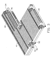
- FIG. 3 is an assembled view of the thermal dissipating device of FIG. 1 ;
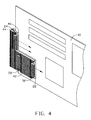
- FIG. 4 is an assembled view of the thermal dissipating device of FIG. 1 and a circuit board.
- a thermal dissipating device in accord unce with an embodiment of the present invention is for cooling electronic components of a circuit board 10, especially for cooling components arranged at edge portions of the circuit board 10.
- a p urality of mounting holes (not shown) is defined around the electronic components of the circuit board 10.
- the thermal dissipating device includes a heat conductive plate 20, a plurality of hea : pipes embedded in the conductive plate 20, a plurality of fin arrays attached to the conductive plate 20, and a plurality of fasteners 50.
- the heat conductive plate 20 is generally L-shaped and includes a first side covering and closely contacting an electronic component of the circuit board 10, and a second side opposite to the first side,
- the conductive plate 20 includes a first part 22, and a second part 24 perpendicularly disposed beside the first part 22.
- a C-shaped channel 222 and two L-shape 1 channels 26 are defined in a second side of the heat conductive plate 20.
- the C-shaped channel 222 is arranged in the first part 22 and the second L-shaped channels 26 extends from the first part 22 o the second part 24.
- a plurality of recesses 224 is defined in the heat conductive plate 20.
- a through hole 226 is defined in each of the recesses 224.
- the plurality of heat pipes includes a C-shaped heat pipe 34, and two L-shaped heat pipes 32, respectively received in the first channel 222 and the second channels 26 of the heat conductive plate 20.
- the plurality of fin arrays includes a first fin array 42, a second fin array 44, and a third fin array 46.
- the first fin array 42 has a generally rectangular shape.
- the second fin array 44 and the third fin array 46 have comparatively narrow rectangular shapes relative to he first fin array 42, and have different lengths.
- a plurality of openings 422 is defined in the first fin array 42.
- a cutout 442 is defined in a corner of the second fin array 44.
- a cutout 462 is defined in a corner of the third fin array 46.
- Each fastener 50 includes a screw 52, a coil spring 54, a gasket 56 and a nut 58.
- the first heat pipe 34 and the second heat pipes 32 are embedded in the C channel 222 and the L channels 26 of the conductive plate 20, respectively.
- the first fin array 42 is attached to the second side of the heat conductive plate 20 by soldering or welding, extending from the first part 22 to the second part 24.
- the second in array 44 is attached to the rest of the second side of the heat conductive plate 20 by soldering or welking, neighboring the first fin array 42.
- the third fin array 46 is attached to the first side of the second part 24 of the conductive plate 20 by soldering or welding. All of fins of the first fin array 42, the sec ond fin array 44, and the third fin array 46 are parallel.
- the screws 52 with the coil springs 54 fined around shafts thereof extend through the openings 422 of the first fin array 42, the cutout 442 of the second fin array 44, and the cutout 462 of the third fin array 46 and the through holes 226 of the heat conductive plate 20.
- the coil springs 54 are received in the recesses 224 of the conductive plate 20 anc abut heads of the screws 52.
- the gaskets 56 are fixed around the shafts of the screws 52 and abut the first side of the conductive plate 20.
- the thermal dissipating device is attached to he circuit board 10, with the shafts of the screws 52 extending through the mounting holes of the circuit board 10 around the electronic component to engage with the nuts 58.
- the first side of first part 22 of the heat conductive plate 20 covers and fully contacts a top surface of the electronic component Heat generated by the electronic component is directly transferred to the first part 22 of the heat cor ductive plate 10 and then transferred to the first fin array 42 via the first heat pipe 34 and portions of he second heat pipes 32.
- the heat of the electronic device is also transferred to the second fin array 44 via the second heat pipes 32 and the second part 24 of the heat conductive plate 20.
- the heat is further transferred to the third fin array 46 by the second heat pipes 32 and the second part 24 of the heat conductive plate 20.
- the electronic component is well cooled not only by the first fin array 42 arranged in a conventional direction perpendicular to the electronic component but also by the second fin array 44 and the third fin array arranged adjacent to the electronic component.
Landscapes
- Engineering & Computer Science (AREA)
- Life Sciences & Earth Sciences (AREA)
- Sustainable Development (AREA)
- Physics & Mathematics (AREA)
- Thermal Sciences (AREA)
- Mechanical Engineering (AREA)
- General Engineering & Computer Science (AREA)
- Cooling Or The Like Of Electrical Apparatus (AREA)
- Cooling Or The Like Of Semiconductors Or Solid State Devices (AREA)
Abstract
Description
- The present invention relates to thermal dissipating devices, and particularly to a thermal dissipating device for cooling an electronic component of a circuit board.
- Thermal dissipation devices are popularly used in electrical device s, such as a computer or a server. Typically, a CPU in the computer or server has a thermal dissipation device for increasing the heat conduction performance. If the performance of the thermal dissipation device is nbt good, the CPU may over-heat losing speed or even failing altogether. Therefore, a good thermal dissipation device is a very important component for electronic devices. A traditional thermal dissipation device for conducting heat to the outside includes a heat sink and a fan. An uppers de of the heat sink usually connects with the fan, and a lower side of the heat sink usually connects with heat producing electronic component (such as a CPU). To get better heat dissipation performance heat pipes may be embedded in a base of the heat sink. However, the heat sink, the fan, and the heat pipes of the traditional thermal dissipation device are typically arranged in a direction pen endicular to the electronic component, which may inhibit heat dissipation efficiency thereof.
- What is desired, therefore, is a thermal dissipating device efficie it in removing heat from electronic components.
- An exemplary thermal dissipating device is for cooling an electronic component of a circuit board. The thermal dissipating device includes a heat conductive plate with a first side and a second side opposite to the first side, a plurality of heat pipes, and a plurality of fin arrays. The heat conductive plate includes a first part with the first side in closely contact with the electronic component, and a second part perpendicularly disposed beside the first part. The heat pipes are embedded in the second side of the conductive plate, extending from the first part to the second part. One of the fin arrays is attached to the second side of the first part of the conductive plan. The others of the fin arrays are attached to the second part of the conductive plate the first and second sides respectively.
- Other advantages and novel features will become more apparent from the following detailed description when taken in conjunction with the accompanying drawings, in which:
-
FIG. 1 is an exploded, isometric view of a thermal dissipating device of an embodiment of the present invention; -
FIG. 2 is a sub-assembly view of the thermal dissipating device ofFIG. 1 ; -
FIG. 3 is an assembled view of the thermal dissipating device ofFIG. 1 ; and -
FIG. 4 is an assembled view of the thermal dissipating device ofFIG. 1 and a circuit board. - Referring to
FIGS. 1 and4 , a thermal dissipating device in accord unce with an embodiment of the present invention is for cooling electronic components of acircuit board 10, especially for cooling components arranged at edge portions of thecircuit board 10. A p urality of mounting holes (not shown) is defined around the electronic components of thecircuit board 10. The thermal dissipating device includes a heatconductive plate 20, a plurality of hea : pipes embedded in theconductive plate 20, a plurality of fin arrays attached to theconductive plate 20, and a plurality offasteners 50. - The heat
conductive plate 20 is generally L-shaped and includes a first side covering and closely contacting an electronic component of thecircuit board 10, and a second side opposite to the first side, Theconductive plate 20 includes afirst part 22, and asecond part 24 perpendicularly disposed beside thefirst part 22. A C-shaped channel 222 and two L-shape 1channels 26 are defined in a second side of the heatconductive plate 20. The C-shaped channel 222 is arranged in thefirst part 22 and the second L-shaped channels 26 extends from the first part 22 o thesecond part 24. A plurality ofrecesses 224 is defined in the heatconductive plate 20. A throughhole 226 is defined in each of therecesses 224. - The plurality of heat pipes includes a C-
shaped heat pipe 34, and two L-shaped heat pipes 32, respectively received in thefirst channel 222 and thesecond channels 26 of the heatconductive plate 20. - The plurality of fin arrays includes a
first fin array 42, asecond fin array 44, and athird fin array 46. Thefirst fin array 42 has a generally rectangular shape. Thesecond fin array 44 and thethird fin array 46 have comparatively narrow rectangular shapes relative to hefirst fin array 42, and have different lengths. A plurality ofopenings 422 is defined in thefirst fin array 42. Acutout 442 is defined in a corner of thesecond fin array 44. Acutout 462 is defined in a corner of thethird fin array 46. - Each
fastener 50 includes ascrew 52, a coil spring 54, a gasket 56 and anut 58. - Referring to
FIGS. 2 and3 , in assembly, thefirst heat pipe 34 and thesecond heat pipes 32 are embedded in theC channel 222 and theL channels 26 of theconductive plate 20, respectively. Thefirst fin array 42 is attached to the second side of the heatconductive plate 20 by soldering or welding, extending from thefirst part 22 to thesecond part 24. The second inarray 44 is attached to the rest of the second side of the heatconductive plate 20 by soldering or welking, neighboring thefirst fin array 42. Thethird fin array 46 is attached to the first side of thesecond part 24 of theconductive plate 20 by soldering or welding. All of fins of thefirst fin array 42, the sec ondfin array 44, and thethird fin array 46 are parallel. Thescrews 52 with the coil springs 54 fined around shafts thereof extend through theopenings 422 of thefirst fin array 42, thecutout 442 of thesecond fin array 44, and thecutout 462 of thethird fin array 46 and the throughholes 226 of the heatconductive plate 20. The coil springs 54 are received in therecesses 224 of theconductive plate 20 anc abut heads of thescrews 52. The gaskets 56 are fixed around the shafts of thescrews 52 and abut the first side of theconductive plate 20. - Referring to
FIG. 4 , the thermal dissipating device is attached to hecircuit board 10, with the shafts of thescrews 52 extending through the mounting holes of thecircuit board 10 around the electronic component to engage with thenuts 58. The first side offirst part 22 of the heatconductive plate 20 covers and fully contacts a top surface of the electronic component Heat generated by the electronic component is directly transferred to thefirst part 22 of the heat corductive plate 10 and then transferred to thefirst fin array 42 via thefirst heat pipe 34 and portions of hesecond heat pipes 32. At the same time, the heat of the electronic device is also transferred to thesecond fin array 44 via thesecond heat pipes 32 and thesecond part 24 of the heatconductive plate 20. The heat is further transferred to thethird fin array 46 by thesecond heat pipes 32 and thesecond part 24 of the heatconductive plate 20. The electronic component is well cooled not only by thefirst fin array 42 arranged in a conventional direction perpendicular to the electronic component but also by thesecond fin array 44 and the third fin array arranged adjacent to the electronic component. - It is believed that the present embodiments and their advantages will be understood from the foregoing description, and it will be apparent that various changes may be made thereto without departing from the spirit and scope of the invention or sacrificing all of its material advantages, the examples hereinbefore described merely being preferred or exemplary embodiments.
Claims (9)
- A thermal dissipating device for cooling an electronic compoment of a circuit board, the thermal dissipating device comprising:a heat conductive plate comprising a first side closely contact ing with the electronic component, and a second side opposite to the first side, the heat conductive plate comprising a first part, and a second part perpendicularly disposed reside the first part;a heat pipe embedded in the second side of the conductive plate and extending from the first part to the second part;a first fin array attached the second side of the first part of the conductive plate and sandwiched the heat pipe therebetween; anda second fin array and a third fin may respectively attached 10 opposite sides of the second part.
- The thermal dissipating device as claimed in claim 1, wherein the conductive plate comprises a first channel defined therein, extending from the first part to the second part, to receive the heat pipe therein.
- The thermal dissipating device as claimed in claim 1 or 2, w herein the heat pipe is generally L-shaped.
- The thermal dissipating device as claimed in claim 2, where n the first part of the conductive plate comprises a second channel define therein beside the first channel to receive a C-shaped heat pipe therein.
- The thermal dissipating device as claimed in any preceding claim, wherein the second fin array is attached to the second part of the heat conductive plate at the same side as the first fin array, sandwiching the first heat pipe between the heat conductive plate and the second fin array.
- The thermal dissipating device as claimed in claim 4, wherein the third fin array is attached to the second part of the heat conductive at an opposite side to the first fin array.
- A circuit assembly comprising:a circuit board comprising a heat-generating electronic component installed thereon and near an edge thereof; and;a thermal dissipation device comprising a heat conductive plate attached on the electronic component, a portion of the conductive plate extending beyond a boundary of the electronic component and leaving a space between the portion of the conductive plate and the circuit board, a plurality of fins extending up from the conductive plate, and a plurality of fins extending down from the portion of the conductive plate and accommodated in the space.
- The circuit assembly as claimed in claim 7, wherein the heat conductive plate comprises a first part, and a second part perpendicularly disposed beside the first part, the first part with a first side closely contacting the electronic component, the second part Extends beyond the circuit board.
- The circuit assembly as claimed in claim 8, wherein the heat dissipation device comprises a plurality of heat pipes embedded in the heat conductive plate extending from the first part to the second part and sandwiched between the conductive plate and the fins.
Applications Claiming Priority (1)
| Application Number | Priority Date | Filing Date | Title |
|---|---|---|---|
| CNU2007202004765U CN201115256Y (en) | 2007-06-15 | 2007-06-15 | heat sink |
Publications (2)
| Publication Number | Publication Date |
|---|---|
| EP2053912A2 true EP2053912A2 (en) | 2009-04-29 |
| EP2053912A3 EP2053912A3 (en) | 2010-04-14 |
Family
ID=39758844
Family Applications (1)
| Application Number | Title | Priority Date | Filing Date |
|---|---|---|---|
| EP08251808A Withdrawn EP2053912A3 (en) | 2007-06-15 | 2008-05-23 | Thermal dissipating device |
Country Status (3)
| Country | Link |
|---|---|
| US (1) | US7576986B2 (en) |
| EP (1) | EP2053912A3 (en) |
| CN (1) | CN201115256Y (en) |
Families Citing this family (25)
| Publication number | Priority date | Publication date | Assignee | Title |
|---|---|---|---|---|
| US7609521B2 (en) * | 2007-09-26 | 2009-10-27 | Fu Zhun Precision Industry (Shen Zhen) Co., Ltd. | Heat dissipation device with a heat pipe |
| US8196645B2 (en) * | 2007-12-27 | 2012-06-12 | Fu Zhun Precision Industry (Shen Zhen) Co., Ltd. | Heat sink with heat pipes |
| CN101528018A (en) * | 2008-03-07 | 2009-09-09 | 富准精密工业(深圳)有限公司 | Heat radiating device and manufacturing method thereof |
| CN101573017B (en) * | 2008-04-28 | 2012-07-04 | 富准精密工业(深圳)有限公司 | Radiating device |
| TWI342486B (en) * | 2008-04-30 | 2011-05-21 | Asustek Comp Inc | Heat-dissipation module and electronic apparatus having the same |
| CN101616565A (en) * | 2008-06-27 | 2009-12-30 | 富准精密工业(深圳)有限公司 | heat sink |
| US20100126700A1 (en) * | 2008-11-24 | 2010-05-27 | Li-Ling Chen | Heat-radiating base plate and heat sink using the same |
| CN101808490A (en) * | 2009-02-17 | 2010-08-18 | 富准精密工业(深圳)有限公司 | Heat dissipating device |
| TW201036527A (en) * | 2009-03-19 | 2010-10-01 | Acbel Polytech Inc | Large-area liquid-cooled heat-dissipation device |
| CN102023689B (en) * | 2009-09-11 | 2013-09-18 | 技嘉科技股份有限公司 | Adjustable cooling module and computer device with the cooling module |
| CN102300441A (en) * | 2010-06-25 | 2011-12-28 | 鸿富锦精密工业(深圳)有限公司 | Electronic device and radiator thereof |
| DE202010014108U1 (en) * | 2010-10-08 | 2010-12-02 | Congatec Ag | Heat spreader with mechanically secured heat coupling element |
| DE202010014106U1 (en) * | 2010-10-08 | 2010-12-16 | Congatec Ag | Heat spreader with flexibly mounted heat pipe |
| TWI576038B (en) * | 2011-07-13 | 2017-03-21 | 鴻準精密工業股份有限公司 | Heat sink |
| CN102891119A (en) * | 2011-07-20 | 2013-01-23 | 鸿富锦精密工业(深圳)有限公司 | Radiating device |
| US20130105112A1 (en) * | 2011-10-31 | 2013-05-02 | Cooler Master Co., Ltd. | Heat sink |
| US20130340977A1 (en) * | 2012-06-21 | 2013-12-26 | Gregory L. Singleton | Heat sink for use in an electronics system |
| US9013874B2 (en) * | 2012-09-12 | 2015-04-21 | Sk Hynix Memory Solutions Inc. | Heat dissipation device |
| US20140202666A1 (en) * | 2013-01-22 | 2014-07-24 | Asia Vital Components Co., Ltd. | Thermal module |
| CN104378949B (en) * | 2013-08-12 | 2017-04-26 | 英业达科技有限公司 | Server and heat dissipation assembly thereof |
| WO2016171654A1 (en) * | 2015-04-20 | 2016-10-27 | Hewlett Packard Enterprise Development Lp | Supplemental air cooling |
| US9750127B2 (en) * | 2015-12-04 | 2017-08-29 | General Electric Company | Circuit card assembly including heat transfer assembly and method of manufacturing such |
| WO2019179259A1 (en) * | 2018-03-21 | 2019-09-26 | Bitmain Technologies Inc. | Chip heat dissipating structure, chip structure, circuit board, and computing device |
| CN217363595U (en) * | 2022-01-17 | 2022-09-02 | 全亿大科技(佛山)有限公司 | Heat radiator |
| CN114928983A (en) * | 2022-04-21 | 2022-08-19 | 浙江众合科技股份有限公司 | Full-automatic vehicle-mounted equipment board card radiator |
Family Cites Families (10)
| Publication number | Priority date | Publication date | Assignee | Title |
|---|---|---|---|---|
| US6058012A (en) * | 1996-08-26 | 2000-05-02 | Compaq Computer Corporation | Apparatus, method and system for thermal management of an electronic system having semiconductor devices |
| US6397941B1 (en) * | 1999-12-01 | 2002-06-04 | Cool Options, Inc. | Net-shape molded heat exchanger |
| US7080680B2 (en) * | 2001-09-05 | 2006-07-25 | Showa Denko K.K. | Heat sink, control device having the heat sink and machine tool provided with the device |
| TW545883U (en) * | 2002-11-20 | 2003-08-01 | Sunonwealth Electr Mach Ind Co | Heat dissipating device |
| CN100543972C (en) * | 2005-08-08 | 2009-09-23 | 富准精密工业(深圳)有限公司 | heat pipe radiator |
| US7520316B2 (en) * | 2005-10-05 | 2009-04-21 | Fu Zhun Precision Industry (Shen Zhen) Co., Ltd. | Heat sink with heat pipes |
| US7493939B2 (en) * | 2005-11-13 | 2009-02-24 | Fu Zhun Precision Industry (Shen Zhen) Co., Ltd. | Heat sink with heat pipes |
| CN100464279C (en) * | 2005-11-17 | 2009-02-25 | 富准精密工业(深圳)有限公司 | heat sink |
| US7440279B2 (en) * | 2006-03-14 | 2008-10-21 | Fu Zhun Precision Industry (Shen Zhen) Co., Ltd. | Heat dissipation device |
| US7405937B1 (en) * | 2007-02-16 | 2008-07-29 | Inventec Corporation | Heat sink module for dual heat sources |
-
2007
- 2007-06-15 CN CNU2007202004765U patent/CN201115256Y/en not_active Expired - Fee Related
- 2007-12-20 US US11/960,742 patent/US7576986B2/en not_active Expired - Fee Related
-
2008
- 2008-05-23 EP EP08251808A patent/EP2053912A3/en not_active Withdrawn
Also Published As
| Publication number | Publication date |
|---|---|
| US20080310122A1 (en) | 2008-12-18 |
| CN201115256Y (en) | 2008-09-10 |
| US7576986B2 (en) | 2009-08-18 |
| EP2053912A3 (en) | 2010-04-14 |
Similar Documents
| Publication | Publication Date | Title |
|---|---|---|
| US7576986B2 (en) | Thermal dissipating device | |
| US7891411B2 (en) | Heat dissipation device having a fan for dissipating heat generated by at least two electronic components | |
| US7967059B2 (en) | Heat dissipation device | |
| US7990719B2 (en) | Electronic system with heat dissipation device | |
| US7542293B2 (en) | Thermal module | |
| US9313923B2 (en) | Multi-component heatsink with self-adjusting pin fins | |
| US20090154105A1 (en) | Heat dissipation device and a method for manufacturing the same | |
| US20090266513A1 (en) | Heat dissipation device | |
| US20050030719A1 (en) | Heat dissipating device for dissipating heat generated by an electronic component inside a housing | |
| CN102065667A (en) | Electronic device and heat radiating device thereof | |
| US20110265976A1 (en) | Heat dissipation device with heat pipe | |
| JP5738679B2 (en) | Heat dissipation structure | |
| US8979575B2 (en) | Electrical connector assembly having assistant heat dissipating device | |
| US6930883B2 (en) | Heat-dispersing module of electronic device | |
| US20080289799A1 (en) | Heat dissipation device with a heat pipe | |
| US20100122795A1 (en) | Heat dissipation device | |
| US7478668B2 (en) | Heat dissipation device | |
| US7694718B2 (en) | Heat sink with heat pipes | |
| US7394656B1 (en) | Heat dissipation device | |
| US11109514B1 (en) | Electronic device with a heat dissipating function and heat dissipating module thereof | |
| JP4438526B2 (en) | Power component cooling system | |
| CN2831718Y (en) | Radiation boards | |
| US20090166007A1 (en) | Heat dissipation device with a heat pipe | |
| US7040389B2 (en) | Integrated heat dissipation apparatus | |
| US20050217825A1 (en) | Heat dissipating sheet and heat dissipating module made of the heat dissipating sheet |
Legal Events
| Date | Code | Title | Description |
|---|---|---|---|
| PUAI | Public reference made under article 153(3) epc to a published international application that has entered the european phase |
Free format text: ORIGINAL CODE: 0009012 |
|
| PUAB | Information related to the publication of an a document modified or deleted |
Free format text: ORIGINAL CODE: 0009199EPPU |
|
| PUAI | Public reference made under article 153(3) epc to a published international application that has entered the european phase |
Free format text: ORIGINAL CODE: 0009012 |
|
| AK | Designated contracting states |
Kind code of ref document: A2 Designated state(s): AT BE BG CH CY CZ DE DK EE ES FI FR GB GR HR HU IE IS IT LI LT LU LV MC MT NL NO PL PT RO SE SI SK TR |
|
| AX | Request for extension of the european patent |
Extension state: AL BA MK RS |
|
| PUAL | Search report despatched |
Free format text: ORIGINAL CODE: 0009013 |
|
| AK | Designated contracting states |
Kind code of ref document: A3 Designated state(s): AT BE BG CH CY CZ DE DK EE ES FI FR GB GR HR HU IE IS IT LI LT LU LV MC MT NL NO PL PT RO SE SI SK TR |
|
| AX | Request for extension of the european patent |
Extension state: AL BA MK RS |
|
| AKY | No designation fees paid | ||
| REG | Reference to a national code |
Ref country code: DE Ref legal event code: 8566 |
|
| STAA | Information on the status of an ep patent application or granted ep patent |
Free format text: STATUS: THE APPLICATION IS DEEMED TO BE WITHDRAWN |
|
| 18D | Application deemed to be withdrawn |
Effective date: 20101015 |