EP2053274A2 - Oil suction system - Google Patents
Oil suction system Download PDFInfo
- Publication number
- EP2053274A2 EP2053274A2 EP08253414A EP08253414A EP2053274A2 EP 2053274 A2 EP2053274 A2 EP 2053274A2 EP 08253414 A EP08253414 A EP 08253414A EP 08253414 A EP08253414 A EP 08253414A EP 2053274 A2 EP2053274 A2 EP 2053274A2
- Authority
- EP
- European Patent Office
- Prior art keywords
- oil
- suction port
- liquid
- level
- strainer
- Prior art date
- Legal status (The legal status is an assumption and is not a legal conclusion. Google has not performed a legal analysis and makes no representation as to the accuracy of the status listed.)
- Granted
Links
Images




Classifications
-
- F—MECHANICAL ENGINEERING; LIGHTING; HEATING; WEAPONS; BLASTING
- F16—ENGINEERING ELEMENTS AND UNITS; GENERAL MEASURES FOR PRODUCING AND MAINTAINING EFFECTIVE FUNCTIONING OF MACHINES OR INSTALLATIONS; THERMAL INSULATION IN GENERAL
- F16H—GEARING
- F16H57/00—General details of gearing
- F16H57/04—Features relating to lubrication or cooling or heating
- F16H57/0402—Cleaning of lubricants, e.g. filters or magnets
-
- F—MECHANICAL ENGINEERING; LIGHTING; HEATING; WEAPONS; BLASTING
- F16—ENGINEERING ELEMENTS AND UNITS; GENERAL MEASURES FOR PRODUCING AND MAINTAINING EFFECTIVE FUNCTIONING OF MACHINES OR INSTALLATIONS; THERMAL INSULATION IN GENERAL
- F16H—GEARING
- F16H57/00—General details of gearing
- F16H57/04—Features relating to lubrication or cooling or heating
- F16H57/0434—Features relating to lubrication or cooling or heating relating to lubrication supply, e.g. pumps; Pressure control
- F16H57/0443—Features relating to lubrication or cooling or heating relating to lubrication supply, e.g. pumps; Pressure control for supply of lubricant during tilt or high acceleration, e.g. problems related to the tilt or extreme acceleration of the transmission casing and the supply of lubricant under these conditions
-
- F—MECHANICAL ENGINEERING; LIGHTING; HEATING; WEAPONS; BLASTING
- F16—ENGINEERING ELEMENTS AND UNITS; GENERAL MEASURES FOR PRODUCING AND MAINTAINING EFFECTIVE FUNCTIONING OF MACHINES OR INSTALLATIONS; THERMAL INSULATION IN GENERAL
- F16H—GEARING
- F16H57/00—General details of gearing
- F16H57/04—Features relating to lubrication or cooling or heating
- F16H57/045—Lubricant storage reservoirs, e.g. reservoirs in addition to a gear sump for collecting lubricant in the upper part of a gear case
- F16H57/0452—Oil pans
-
- F—MECHANICAL ENGINEERING; LIGHTING; HEATING; WEAPONS; BLASTING
- F16—ENGINEERING ELEMENTS AND UNITS; GENERAL MEASURES FOR PRODUCING AND MAINTAINING EFFECTIVE FUNCTIONING OF MACHINES OR INSTALLATIONS; THERMAL INSULATION IN GENERAL
- F16H—GEARING
- F16H61/00—Control functions within control units of change-speed- or reversing-gearings for conveying rotary motion ; Control of exclusively fluid gearing, friction gearing, gearings with endless flexible members or other particular types of gearing
- F16H61/0003—Arrangement or mounting of elements of the control apparatus, e.g. valve assemblies or snapfittings of valves; Arrangements of the control unit on or in the transmission gearbox
- F16H61/0009—Hydraulic control units for transmission control, e.g. assembly of valve plates or valve units
Definitions
- the invention relates to an oil suction system, and in particular to an oil suction system provided in a lower part of an automatic transmission of a vehicle.
- an oil suction system is installed which includes an oil pan mounted on the bottom of the power transmitting system, in order to improve the capability of collecting oil to be supplied to and discharged from the hydraulic circuit.
- the oil pan is often required to have a shallow depth so as to ensure a sufficient ground clearance of the vehicle, while it is necessary to prevent air from being drawn up even if the liquid level of the oil near a suction port is lowered.
- JP-A-10-121933 discloses an oil suction system for use in the engine, in which a pair of partition walls that are opposed to each other are provided in the vicinity of the interface of two casings, so as to form an oil suction space having two oil chambers with different amounts of oil stored therein, and a suction port is slightly inclined at the inlet of the oil suction space so that the larger amount of oil is drawn from one of the above-indicated oil chambers in which the larger amount of oil is stored.
- JP-U-5-90020 discloses an oil suction system of an automatic transmission in which an oil pan having a reduced depth is often used, a strainer is supported onto a valve body at a position remote from a suction port such that the strainer is rotatable about the position (support) in a horizontal plane, and a weight is mounted at the suction-port side of the strainer, so that the suction port moves in a direction in which the oil in a reservoir moves during acceleration, deceleration, turning or braking of the vehicle, thereby to prevent drawing of air into the strainer.
- JP-A-2007-56677 discloses an oil suction system of an engine, in which a strainer is located close to the inner surface of the bottom of an oil pan and extends in the longitudinal direction, and an opening (suction port) formed in a rear end portion of the strainer is inclined such that the distance between the opening and the inner bottom surface of the oil pan increases from the front end to the rear end of the opening.
- This arrangement is developed in view of the situation where the oil moves to the rear side of the oil pan during uphill running or upon rapid acceleration, and the liquid level is lowered at the front side and is raised at the rear side.
- the oil chambers are formed by providing the mutually opposed partition walls at the interface of the cases, or the suction port is made movable in the direction of movement (shift) of the oil, thus making the construction of the system complicated and increasing the cost of manufacture of the system.
- the suction port is located in a longitudinally middle portion of the oil pan, and the rear end portion of the strainer needs to be supported onto the oil pan, which makes the construction of the system complicated. Furthermore, the oil suction system thus constructed cannot be expected to provide a sufficient effect of preventing drawing of air if it is employed as an oil suction system of an automatic transmission in which the depth of the oil pan is further reduced, and the strainer assumes a flattened shape extending in a horizontal plane.
- the amount of oil stored in the transmission needs to be reduced for an improvement in the efficiency particularly at high oil temperatures and for reduction in weight. If the amount of the oil stored is reduced, however, a low-oil-level portion (in which the amount of oil drawn into the strainer is larger than the amount of oil supplied to this portion) appears in the oil pan when the transmission is inclined at a low temperature (e.g., at about 0°C), and drawing (suck-up) of air is likely to occur at the low-oil-level portion.
- a low-oil-level portion in which the amount of oil drawn into the strainer is larger than the amount of oil supplied to this portion
- the level of the liquid surface (the liquid level) close to the suction port of the strainer upon inclination varies greatly even with the same oil amount. Furthermore, the oil supplied to the oil pan does not evenly or uniformly flow into the suction port, because of the layout of the interior of the oil pan, and a portion having a small amount of oil appears in the oil pan. For these reasons, and others, drawing (suck-up) of air into the oil pump occurs even where the suction port that is located in the central portion of the oil pan and is open backward while being inclined is provide at the rear end of the strainer that extends in the longitudinal direction. As a result, abnormal or unusual sound due to entry of air into gears may occur in an oil pump constituted solely by a gear pump, or poor pressure regulation may occur due to entry of air into a valve body.
- the present invention provides an oil suction system that is simple in construction and prevents drawing of air.
- One aspect of the invention relates to an oil suction system including oil storage means for storing oil to be supplied to and discharged from a hydraulic circuit installed on a vehicle, in an oil pan, and a strainer having a suction port that faces to an inner bottom surface of the oil pan, wherein the oil stored in the oil storage means is drawn up through the strainer.
- the oil storage means is constructed such that, when a liquid surface of the oil is inclined due to movement of the oil stored in the oil storage means, a level of the liquid surface close to the suction port varies in accordance with a plurality of directions of inclination of the liquid surface, and the level of the liquid surface close to the suction port is lower in a particular direction as one of the above-indicated plurality of directions of inclination of the liquid surface, than those in the other directions of inclination, and inflow resistance means is provided at a lowered liquid-level side of the suction port on which the level of the liquid surface is lowered when the liquid surface is inclined in said particular direction, for increasing the resistance to flow of the oil from the lowered liquid-level side toward the suction port, to be larger than the resistance to flow of the oil from a raised liquid-level side of the suction port on which the level of the liquid surface is raised due to inclination of the liquid surface in the particular direction, toward the suction port.
- the inflow resistance is increased on the lowered liquid-level side of the suction port on which the liquid level is lowered, while the inflow resistance is reduced on the raised liquid-level side of the suction port on which the liquid level is raised, whereby air is less likely or unlikely to be drawn into the strainer.
- the suction port may be located within a liquid-level assurance region in which the level of the liquid surface close to the suction port is higher than the level of the suction port no matter which direction in which the liquid surface is inclined.
- the inflow resistance means may have a shielding plate that is provided at the lowered liquid-level side of the suction port and protrudes into an oil passage between the strainer and the inner bottom surface of the oil pan so as to reduce the cross-sectional area of the oil passage.
- the inflow resistance means is simply constructed by providing the shielding plate.
- the shielding plate may be constructed such that the height of the shielding plate as measured in a direction of protrusion thereof into the oil passage is large on the lowered liquid-level side and on a side remote from a center of the suction port, and is small on a side close to the center of the suction port, and the shielding plate located in the vicinity of the suction port may surround a part of the circumference of the suction port on the lowered liquid-level side with respect to the center of the suction port.
- the inflow of the oil from the lowered liquid-level side in the particular direction can be more effectively restricted, and the liquid level is prevented from being locally lowered in the vicinity of the suction port at a low temperature.
- the inflow resistance means may consist of a part of the bottom of the strainer, and the above-indicated part of the bottom of the strainer may be located closer to the inner bottom surface of the oil pan than the other part of the bottom so as to reduce a cross-sectional area of an oil passage between the strainer and the inner bottom surface of the oil pan at the lowered liquid-level side of the suction port.
- the inflow resistance means can be provided without installing another component or components, thus making the system simple in construction.
- a difference in an oil storage capacity between one side and the other side of the suction port in the oil storage means may vary in accordance with the above-indicated plurality of directions of inclination of the liquid surface, and the difference in the oil storage capacity between one side and the other side of the suction port may be larger in the particular direction than those in the other directions of inclination, while the oil storage capacity may be at the maximum on the raised liquid-level side of the suction port when the liquid surface is inclined in the particular direction.
- the particular direction of inclination is set in view of the uneven distribution of the oil storage capacity of the oil storage means with respect to the position of the suction port as well as the oil pan.
- the hydraulic circuit may be provided in a power transmitting system of the vehicle, and a valve body in which a plurality of valves as part of the hydraulic circuit are housed may be disposed above the strainer, such that an oil suction passage in the strainer communicates with an interior of the valve body.
- the strainer is disposed below the valve body, and, even if the spacing between the lower face of the strainer and the inner bottom surface of the oil pan is reduced, inflow of oil from the lowered liquid-level side of the suction port is restricted, and drawing of air is prevented.
- the power transmitting system may be an automatic transmission.
- the inflow resistance on the lowered liquid-level side of the suction port on which the liquid level is lowered is increased, and the inflow resistance on the raised liquid-level side of the suction port on which the liquid level is raised is reduced. It is thus possible to provide an oil suction system which is simple in construction and can prevent drawing of air with reliability.
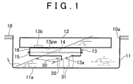
- FIG. 1 is a view schematically showing the construction of an oil suction system according to a first embodiment of the invention.
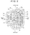
- FIG. 2 is a bottom view of a principal part of the oil suction system in a condition in which an oil pan of an automatic transmission (power transmitting system) on which the oil suction system is installed is removed from the system.
- the oil suction system of this embodiment is mounted on the lower-face side of a case 10 of the automatic transmission (which will be called "transmission case 10"), and the transmission case 10 is formed with an opening 10a that receives an oil pan 11.
- a valve body 12 is provided in an upper part of the oil pan 11 to extend over substantially the entire area of the opening 10a, and a strainer 13 is provided under the valve body 12.
- An oil pump in the form of a gear pump (e.g., a gear pump having a trochoid tooth profile) that is not illustrated is provided in the transmission case 10.
- the oil is drawn up by the oil pump through a strainer 13 while being filtered by the strainer 13, and is then supplied to various elements in the valve body 12 and various hydraulically operating parts and lubrication parts in the transmission case 10. Then, return oil that returns from these elements and parts drops into the oil pan 11.
- the valve body 12 which is not illustrated in detail, includes hydraulic actuators for engaging and disengaging various friction coupling elements for shifting, which are disposed in the transmission case 10, supply/discharge control valves for supplying and discharging the oil serving as working fluid to and from the hydraulic actuators, pressure regulating valves for regulating the hydraulic pressures and accumulators (pressure accumulating elements), solenoid valves for switching various valves, and so forth.
- the valve body 12 constitutes a part of a hydraulic circuit provided in the transmission case 10.
- the line pressure based on which engaging pressures of the individual friction coupling elements in the transmission case 10 are regulated is generated from an output port of a regulator valve, and the throttle pressure is regulated by throttle pressure regulating means including a linear solenoid valve(s) into a hydraulic pressure corresponding to the engine output torque, while the converter pressure and lubricating oil pressure suitable for the vehicle speed and the engine output or power is regulated on the basis of the throttle pressure.
- a reverse range pressure is supplied from the manual valve when the reverse-drive range is selected, and, when a forward-drive range (for example, D, 2, 1) is selected, hydraulic pressures are supplied and discharged via appropriate shift valve(s) and accumulator(s) so as to actuate the friction coupling element(s) corresponding to the selected gear position or range.
- a forward-drive range for example, D, 2, 1
- the oil supplied to respective parts of the transmission is fed from the valve body 12 to an oil cooler where the oil is cooled, and excess oil returns to the oil pan via a cooler bypass valve.
- the strainer 13 includes a strainer member 14 serving as a filter for filtering oil, and lower case 15 and upper case 16 that are opposed to each other in the vertical direction with the strainer member 14 sandwiched therebetween.
- the strainer member 14 and the lower and upper cases 15, 16 cooperate to form a suction passage 13pw that communicates with the interior of the valve body 12, and a generally oval suction port 13a is formed in the bottom of the lower case 15 such that the suction port 13a faces an inner bottom surface 11a of the oil pan 11.
- a connection port 13b that is connected to an oil passage that leads to the oil pump is formed in the upper case 16, and the oil that has passed through and has been filtered by the strainer member 14 is drawn up into the oil pump through the connection port 13b.
- the strainer 13 is fastened to the valve body 12 with a plurality of bolts 19, to be supported by the valve body 12.
- part of the oil supplied to the oil cooler drops into an upper right-hand portion (in FIG. 2 ) of the oil pan 11 (e.g., a portion close to the left, front side of the transmission) through a pressure side strainer 21 as shown in FIG 2 .
- the oil that has bypassed the oil cooler for example, is drained toward the front side of the transmission, from a cooler bypass port 22 that protrudes from the valve body 12, upwardly of the strainer 13, and is open to the upper side as viewed in FIG 2 (e.g., the front side of the transmission).
- Another return oil drops toward the lower side as viewed in FIG 2 (e.g., the rear side of the transmission) in the oil pan 11 through a port or drain hole (not shown).
- An overflow tube 23 is provided in the vicinity of the cooler bypass port 22, for allowing excess oil to be discharged outside when an excessive amount of oil is introduced. With this arrangement, the oil is less likely to circulate into an upper, left-side portion (in FIG 2 ) of the oil pan 11 (a portion close to the right, front side of the transmission), which is close to the overflow tube 23.
- the oil pan 11 that serves as a reservoir in the oil circulation network as described above and the transmission case 10 constitute oil storage means for storing oil to be supplied to and discharged from the hydraulic circuit installed on the vehicle, and the oil storage means, the above-mentioned oil pump and the strainer 13 constitute the oil suction system that draws up the oil stored in the oil storage means through the strainer 13.
- the oil storage capacity (volume) is different between at least one direction, out of the front, rear, left and right directions with respect to the center position of the suction port 13a, and the other direction(s). Accordingly, when the oil stored in the transmission case 10 moves toward one side of the oil pan 11 upon acceleration, deceleration or turning during running of the vehicle, or due to an inclined road surface or driving reaction force, and the liquid surface L of the oil is inclined due to the movement of the oil, the liquid level (i.e., the level of the liquid surface L) in the neighborhood of the suction port 13a changes depending on the direction of inclination of the liquid surface L.
- the level of the liquid surface L in the neighborhood of the suction port 13a is lowered to the lowest position when the liquid surface L is inclined in the particular direction.
- the oil storage capacity reaches the maximum on the raised liquid-level side of the suction port 13a on which the liquid level is raised.
- the level of the liquid surface L close to the suction port 13a is lowered to the minimum when the oil moves backward and the liquid surface L is inclined in the longitudinal direction (the particular direction of inclination).
- the suction port 13a is located within a liquid-level assurance region A (a crosshatched region in FIG. 3A ) in which the level of the liquid surface L close to the suction port 13a is higher than the level of the suction port 13a no matter which direction in which the liquid surface L is inclined. While the liquid-level assurance region A is close to a central portion of the oil pan 11, the center of the region A deviates from the center of the oil pan 11, according to differences among the oil storage capacities (volumes) as measured in the front, rear, left and right directions, as shown in FIG 2 .
- the liquid-level assurance region A is set in the following manner: the amount of shift of the center of gravity of the oil in the transmission case 10 is specified, as shown in FIG. 3A by way of example, when the transmission case 10 is inclined by the maximum possible angle of inclination of the liquid surface which is conceivable under running conditions of the actual vehicle, in each of a plurality of directions, such as frontward, rearward, leftward and rightward, that depend on the shape of the transmission case 10, or in the particular direction in which the difference in the oil storage capacity between one side and the other side of the suction port 13a or the total oil storage capacity is at the maximum, and the rotational speed of the oil pump is varied from the maximum to the minimum.
- inflow resistance means 30 is provided at one side of the suction port 13a on which the liquid level is lowered (which will be called “lowered liquid-level side") due to inclination of the liquid surface L in the particular direction (for example, one side of the suction port 13a facing the front side of the transmission case 10), for increasing the resistance to flow of the oil from the lowered liquid-level side into the suction port 13a, to be larger than the resistance to flow of the oil from the side on which the liquid level is raised due to inclination of the liquid surface L in the particular direction (for example, one side of the suction port 13a facing the rear side of the transmission case 10) into the suction port 13a.
- lowered liquid-level side due to inclination of the liquid surface L in the particular direction
- the inflow resistance means 30 has a shielding plate 32 disposed, for example, on the lowered liquid-level side of the suction port 13a.
- the shielding plate 32 protrudes into an oil passage 31 (see FIG. 1 ) between the strainer 13 and the inner bottom surface 11a of the oil pan 11 so as to reduce the cross-sectional area of the oil passage 31, thereby to restrict flow of the oil through the oil passage 31.
- the shielding plate 32 located in the vicinity of the suction port 13a surrounds about one half of the circumference of the suction port 13a on the lowered liquid-level side with respect to the center of the suction port 13a (see FIG. 1 ), and the height of the shielding plate 32 as measured in the direction of protrusion thereof into the oil passage 31 is relatively large on the side on which the liquid level is lowered when the liquid surface is inclined in the particular direction and on the side remote from the center of the suction port 13a, and is relatively small on the side close to the center of the suction port 13a.
- the shielding plate 32 is formed of, for example, metal, or resin, or the like, and has a cross-sectional shape having a relatively large thickness at its proximal end and a relatively small thickness at its distal end, as shown in FIG 3B .
- the shielding plate 32 is fixed integrally to the lower case 15 of the strainer 13, by caulking or other known fitting or engaging method.
- the shielding plate 32 may be formed integrally with the lower case 15 of the strainer 13 made of a sheet metal, or the lower case 15 may be subjected to partial bending or extruding (including drawing) during press working so as to form the shielding plate 32.
- the shielding plate 32 may have a constant thickness from the proximal end to the distal end.
- the inflow resistance is increased on the lowered liquid-level side of the suction port 13a on which the amount of the oil is reduced, and the inflow resistance is reduced on the raised liquid-level side of the suction port 13a on which the amount of the oil is increased, whereby air is less likely or unlikely to be drawn into the suction port 13a.
- the suction port is located within the liquid-level assurance region A in which the level of the liquid surface L close to the suction port 13a is higher than that of the suction port 13a no matter which direction in which the liquid surface L is inclined, and therefore, drawing of air into the oil pump can be prevented with reliability.
- the inflow resistance means 30 may be simply constructed by providing the shielding plate 32.
- the shielding plate 32 located in the vicinity of the suction port 13a surrounds about one half of the circumference of the suction port 13a on the lowered liquid-level side with respect to the center of the suction port 13a (see FIG. 2 and FIG 3B ), such that the height of the shielding plate 32 as measured in the direction of protrusion thereof into the oil passage 31 is relatively large on the lowered liquid-level side and on the side remote from the center of the suction port 13a, and is relatively small on the side close to the center of the suction port 13a.
- the particular direction of inclination of the liquid surface L is determined in view of the distribution of the oil storage capacity of the oil storage means with respect to the position of the suction port 13a as well as the oil pan 11. Therefore, even if the difference in the oil storage capacity between both sides of the suction port 13a is large and the liquid level is greatly lowered in the transmission case 10 having a narrow oil passage 31 as a spacing between the lower face of the strainer 13 and the inner bottom surface 11a of the oil pan 11, the inflow of the oil from the lowered liquid-level side of the suction port 13a upon inclination of the liquid surface L is surely restricted, and drawing of air into the oil pump is prevented with reliability. Even in an oil suction system in which the depth of the oil pan 11 is further reduced to ensure a sufficient ground clearance and the strainer 13 has a flattened shape extending in the horizontal plane, drawing of air into the oil pump is prevented with reliability.
- the oil suction system of this embodiment when the liquid surface L of the oil is inclined in the particular direction in which the liquid level is most likely to be lowered, the inflow resistance on the lowered liquid-level side of the suction port 13a on which the liquid level is lowered is increased, while the inflow resistance on the raised liquid-level side on which the liquid level is raised is reduced.
- the oil suction system of this embodiment which is simple in construction, is able to prevent drawing of air into the oil pump with reliability.
- FIG 4A is a side cross-sectional view schematically showing the construction of an oil suction system according to a second embodiment of the invention
- FIG 4B is a view as seen in the direction of arrow B4 in FIG 4A .
- Each of the embodiments as described below is different from the above-described first embodiment in the arrangement of the suction port of the strainer and its vicinity, but is similar in construction to the above-described embodiment with respect to the other components or parts.
- the same reference numerals as used in FIG. 1 through FIG 3B are used for identifying corresponding components or elements, and only the difference(s) from the first embodiment will be described in detail.
- a strainer 43 of this embodiment includes a strainer member 14 as a known filter for filtering oil, and lower case 45 and upper case 46 that are opposed to each other in the vertical direction with the strainer member 14 sandwiched therebetween.
- the strainer member 14 and the lower and upper cases 45, 46 cooperate to form a suction passage 43pw that communicates with the interior of the valve body 12, and a generally oval suction port 43a as shown in FIG. 4B is formed in the bottom of the lower case 45 such that the suction port 43a is open in a direction that is inclined relative to the inner bottom surface 11a of the oil pan 11.
- a connection port 43b that is connected to an oil passage that leads to the oil pump is formed in the upper case 46, and the oil that has passed through and has been filtered by the strainer member 14 is drawn up from the connection port 43b into the oil pump.
- inflow resistance means 30 is provided in this embodiment at one side of the suction port 43a on which the liquid level is lowered due to inclination of the liquid surface L in a particular direction (in this embodiment, one side of the suction port 43a facing the left-hand side of the transmission case 10 as shown in FIG. 4A .
- the inflow resistance means 30 serves to increase the resistance to flow of the oil from the lowered liquid-level side toward the suction port 43a, to be larger than the resistance to flow of the oil from the side on which the liquid level is raised due to inclination of the liquid surface L in the particular direction (in this embodiment, one side of the suction port 43a facing the right-hand side of the transmission case 10 as shown in FIG 4A ) toward the suction port 43a.
- the inflow resistance means 30 has a shielding plate 33 disposed, for example, on the lowered liquid-level side of the suction port 43a.
- the shielding plate 33 protrudes into the oil passage 31 between the strainer 43 and the inner bottom surface 11a of the oil pan 11 so as to reduce the cross-sectional area of the oil passage 31, thereby to restrict flow of the oil through the oil passage 31.
- the shielding plate 33 located in the vicinity of the suction port 43a surrounds about one half of the circumference of the suction port 43a on the lowered liquid-level side with respect to the center of the suction port 13a.
- the height of the shielding plate 33 as measured in the direction of protrusion thereof into the oil passage 31 is relatively large on the side on which the liquid level is lowered when the liquid surface is inclined in the particular direction and on the side remote from the center of the suction port 13a, and is relatively small on the side close to the center of the suction port 13a.
- the shielding plate 33 is formed integrally on the strainer 43 by partial or local bending or extruding during press working of the lower case 45 made of a sheet metal.
- This embodiment is different from the above-described first embodiment in that the suction port 43a is open in the direction that is inclined relative to the inner bottom surface 11a of the oil pan 11. It is to be understood that the shape of the opening of the suction port 43a is not limited to that shown in FIG 4B , but may be selected from other shapes.
- the inflow resistance is increased on the lowered liquid-level side of the suction port 43a on which the amount of the oil is reduced, and the inflow resistance is reduced on the raised liquid-level side of the suction port 43a on which the amount of the oil is increased, so that air is less likely or unlikely to be drawn into the strainer 43 through the suction port 43a, and thus substantially the same effect as that of the above-described embodiment is provided.
- the suction port 43a is located within the liquid-level assurance region A in which the level of the liquid surface L close to the suction port 43a is higher than that of the suction port 43a no matter which direction in which the liquid surface L is inclined, and therefore, drawing of air into the strainer 43 (or the oil pump) can be prevented with reliability.
- the shielding plate 33 located in the vicinity of the suction port 43a surrounds about one half of the circumference of the suction port 43a on the lowered liquid-level side with respect to the center of the suction port 43a, such that the height of the shielding plate 33 as measured in the direction of protrusion thereof into the oil passage 31 is relatively large on the lowered liquid-level side and on the side remote from the center of the suction port 43a, and is relatively small on the side close to the center of the suction port 43a.
- the shielding plate 33 of this embodiment when viewed in a section of FIG. 4A , extends in a slanting direction with respect to the inner bottom surface of the oil pan 11.
- the thus shaped shielding plate 33 protrudes in the direction of the depth of the liquid (oil), thus assuring the required distance or spacing from the liquid surface L.
- the shielding plate 33 keeps the required distance or spacing from the liquid surface L, and also alleviates an impact to the strainer 43.
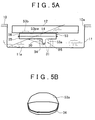
- FIG 5A is a side cross-sectional view schematically showing the construction of an oil suction system according to a third embodiment of the invention
- FIG 5B is a view as seen in the direction of arrow B5 in FIG 5A .
- a strainer 53 of this embodiment includes a strainer member 14 as a known filter for filtering oil, and lower case 55 and upper case 56 that are opposed to each other in the vertical direction with the strainer member 14 sandwiched therebetween.
- the strainer member 14 and the lower and upper cases 55, 56 cooperate to form a suction passage 53pw that communicates with the interior of the valve body 12, and a suction port 53a as shown in FIG 5B is formed in the bottom of the lower case 55 such that the suction port 53a is open in a direction that is inclined relative to the inner bottom surface 11a of the oil pan 11.
- a connection port 53b that is connected to an oil passage that leads to the oil pump is formed in the upper case 56, and the oil that has passed through and has been filtered by the strainer member 14 is drawn up from the connection port 53b into the oil pump.
- inflow resistance means 30 is provided at one side of the suction port 53a on which the liquid level is lowered due to inclination of the liquid surface L in a particular direction (in this embodiment, one side of the suction port 53a facing the left-hand side of the transmission case 10, as shown in FIG 5A ).
- the inflow resistance means 30 serves to increase the resistance to flow of the oil from the lowered liquid-level side toward the suction port 53a, to be larger than the resistance to flow of the oil from the side on which the liquid level is raised due to inclination of the liquid surface L in the particular direction (in this embodiment, one side of the suction port 53a facing the right-hand side of the transmission case 10, as shown in FIG 5A ) toward the suction port 53a.
- the inflow resistance means 30 has a shielding plate 34 disposed on the lowered liquid-level side of the suction port 53a, as shown in FIG 5A .
- the shielding plate 34 protrudes into the oil passage 31 between the strainer 53 and the inner bottom surface 11a of the oil pan 11 while bending at some midpoint thereof so as to reduce the cross-sectional area of the oil passage 31, thereby to restrict flow of the oil through the oil passage 31.
- the shielding plate 34 located in the vicinity of the suction port 53a surrounds about one half of the circumference of the suction port 53a on the lowered liquid-level side with respect to the center of the suction port 53a. Also, the height of the shielding plate 34 as measured in the direction of protrusion thereof into the oil passage 31 is relatively large on the side on which the liquid level is lowered when the liquid surface is inclined in the particular direction and on the side remote from the center of the suction port 53a, and is relatively small on the side close to the center of the suction port 53a.
- the shielding plate 34 is formed integrally on the strainer 53 by partial bending or extruding during press working of the lower case 55 made of, for example, a sheet metal.
- the shielding plate 34 protrudes into the oil passage 31 while bending in a L-shaped cross section as shown in FIG. 5A , such that its bent portion (distal end portion) extends in parallel with the inner bottom surface of the oil pan 11 with a certain spacing therebetween.
- the distal end of the shielding plate 34 is located at a deep point (level) in the liquid, thus assuring the required distance or spacing from the liquid surface L.
- the shielding plate 34 thus shaped possesses high rigidity, the shielding plate 34 is kept spaced a suitable distance from the liquid surface L even if the spacing between the strainer 53 and the oil pan 11 is reduced or the strainer 53 and the oil pan 11 interfere with each other upon interference of the oil pan 11 with the road surface, for example.
- FIG. 6 is a side cross-sectional view schematically showing the construction of an oil suction system according to a fourth embodiment of the invention.
- a strainer 63 of this embodiment includes a strainer member 14 as a known filter for filtering oil, and lower case 65 and upper case 66 that are opposed to each other in the vertical direction with the strainer member 14 sandwiched therebetween.
- the strainer member 14 and the lower and upper cases 65, 66 cooperate to form a suction passage 63pw that communicates with the interior of the valve body 12, and a generally oval suction port 63a is formed in the bottom of the lower case 65 such that the suction port 63a is opposed to a generally horizontal, inner bottom surface 11a of the oil pan 11 of which a part 11b of the bottom is inclined.
- connection port 63b that is connected to an oil passage that leads to the oil pump is formed in the upper case 66, and the oil that has passed through and has been filtered by the strainer member 14 is drawn up from the connection port 63b into the oil pump.
- inflow resistance means 30 is provided at one side of the suction port 63a on which the liquid level is lowered due to inclination of the liquid surface L in a particular direction (in this embodiment, one side of the suction port 63a facing the left-hand side of the transmission case 10, as shown in FIG. 6 ).
- the inflow resistance means 30 serves to increase the resistance to flow of the oil from the lowered liquid-level side toward the suction port 63a, to be larger than the resistance to flow of the oil from the side on which the liquid level is raised due to inclination of the liquid surface L in the particular direction (in this embodiment, one side of the suction port 63a facing the right-hand side of the transmission case 10, as shown in FIG 6 ) toward the suction port 63a.
- the inflow resistance means 30 consists of a part of the lower case 65 (bottom portion) of the strainer 63. More specifically, a part of the bottom of the lower case 65 is shaped to be closer to the inclined part 11b (inner surface) of the oil pan 11 than the other part of the bottom of the lower case 65, so as to reduce the cross-sectional area of the oil passage 31 between the lower case 65 and the inner bottom surface 11a of the oil pan 11 on the lowered liquid-level side of the suction port 63a as viewed in the particular inclination direction. Namely, a bulging portion 35 that bulges toward the bottom of the oil pan 11 from the two-dot chain line in FIG. 6 representing the shape of the other part of the strainer 63 is formed integrally with the strainer 63 so as to locally increase the thickness of the strainer 63.
- the effective inflow resistance means can be easily constructed without installing another component, thus making the system simple in construction.
- the storage capacity in the oil strainer 63 is increased, and the area of the felt mounted on the inner surface of the oil strainer 63 is increased, so that the inflow resistance of the suction passage 63pw in the strainer 63 can be reduced, and cavitation during drawing of the oil can be prevented with reliability.
- FIG. 7 is a side cross-sectional view schematically showing the construction of an oil suction system according to a fifth embodiment of the invention.
- a strainer 73 of this embodiment includes a strainer member 14 as a known filter for filtering oil, and lower case 75 and upper case 76 that are opposed to each other in the vertical direction with the strainer member 14 sandwiched therebetween.
- the strainer member 14 and the lower and upper cases 75, 76 cooperate to form a suction passage 73pw that communicates with the interior of the valve body 12, and a generally oval suction port 73a is formed in the bottom of the lower case 75, such that the suction port 73a is opposed to a generally horizontal, inner bottom surface 11a of the oil pan 11 of which a part 11b of the bottom is inclined.
- connection port 73b that is connected to an oil passage that leads to the oil pump is formed in the upper case 76, and the oil that has passed through and has been filtered by the strainer member 14 is drawn up from the connection port 73b into the oil pump.
- inflow resistance means 30 is provided at one side of the suction port 73a on which the liquid level is lowered due to inclination of the oil surface L in a particular direction (in this embodiment, one side of the suction port 73a facing the left-hand side of the transmission case 10, as shown in FIG. 7 ).
- the inflow resistance means 30 serves to increase the resistance to flow of the oil from the lowered liquid-level side toward the suction port 73a, to be larger than the resistance to flow of the oil from the side on which the liquid level is raised due to inclination of the liquid surface L in the particular direction (in this embodiment, one side of the suction port 73a facing the right-hand side of the transmission case 10, as shown in FIG. 7 ) toward the suction port 73a.
- the inflow resistance means 30 consists of a part of the lower case 75 (bottom portion) of the strainer 73. More specifically, a longitudinally middle portion of the bottom of the lower case 75 is shaped to be closer to the inner bottom surface 11a of the oil pan 11 than the other portion of the bottom of the lower case 75, so as to reduce the cross-sectional area of the oil passage 31 between the lower case 75 and the inner bottom surface 11a of the oil pan 11 on the lowered liquid-level side of the suction port 73a as viewed in the particular inclination direction. Namely, a bulging portion 36 that bulges toward the bottom of the oil pan 11 from the two-dot chain line in FIG.
- the cross-sectional area of the oil passage 31 between the strainer 73 and the inner bottom surface 11 a of the oil pan 11 gradually decreases from the left end in FIG 7 toward the suction portion 73a until the oil passage 31 reaches the lowest point 36a of the bulging portion 36, and increases in the vicinity of the suction port 73 (i.e., from the lowest point 36a to the suction port 73).
- FIG. 8 is a side cross-sectional view schematically showing the construction of an oil suction system according to a sixth embodiment of the invention.
- a strainer 83 of this embodiment includes a strainer member 14 as a known filter for filtering oil, and lower case 85 and upper case 86 that are opposed to each other in the vertical direction with the strainer member 14 sandwiched therebetween.
- the strainer member 14 and the lower and upper cases 85, 86 cooperate to form a suction passage 83pw that communicates with the interior of the valve body 12, and a generally oval suction port 83a is formed in the bottom of the lower case 85 such that the suction port 83a is opposed to a generally horizontal, inner bottom surface 11a of the oil pan 11 of which a part 11b of the bottom is inclined.
- a connection port 83b that is connected to an oil passage leading to the oil pump is formed in the upper case 86, and the oil that has passed through and has been filtered by the strainer member 14 is drawn up from the connection port 83b into the oil pump.
- inflow resistance means 30 is provided at one side of the suction port 83a on which the liquid level is lowered due to inclination of the liquid surface L in a particular direction (in this embodiment, one side of the suction port 83a facing the left-hand side of the transmission case 10, as shown in FIG. 8 ).
- the inflow resistance means 30 serves to increase the resistance to flow of the oil from the lowered liquid-level side toward the suction port 83a, to be larger than the resistance to flow of the oil from the side on which the liquid level is raised due to inclination of the liquid surface L in the particular direction (in this embodiment, one side of the suction port 83a facing the right-hand side of the transmission case 10, as shown in FIG 8 ) toward the suction port 83a.
- the inflow resistance means 30 consists of a part of the lower case 85 (bottom portion) of the strainer 83. More specifically, a portion of the bottom of the lower case 85 which extends from the left end in FIG 8 to the vicinity of the suction portion 83a is shaped to be closer to the inner bottom surface 11a of the oil pan 11 than the other portion (closer to the right end in FIG 8 ) of the bottom of the lower case 85, so as to reduce the cross-sectional area of the oil passage 31 between the lower case 85 and the inner bottom surface 11a of the oil pan 11 on the lowered liquid-level side of the suction port 83a as viewed in the particular inclination direction.
- a bulging portion 37 that bulges toward the bottom of the oil pan 11 from the two-dot chain line in FIG 8 representing the shape of the other portion is formed integrally with the strainer 83 so as to locally increase the thickness of the strainer 83.
- the cross-sectional area of the oil passage 31 between the strainer 83 and the inner bottom surface 11 a of the oil pan 11 gradually decreases from the left end in FIG 8 toward the suction portion 83a until the oil passage 31 reaches the lowest point 37a of the bulging portion 37, and suddenly increases in the vicinity of the suction port 83.
- the cross-sectional area of the oil passage 31 in the vicinity of the lowest point 37a of the bulging portion 37 is largely different from that of the oil passage 31 right below the suction port 83a.
- the above-mentioned particular direction of inclination may be a slanting direction that is inclined a certain angle relative to the longitudinal direction of the vehicle, depending on the shape of the transmission case 10 and the orientation of the case 10 when installed on the vehicle.
- the shielding plate may have a curved cross-section, or an arc-shaped bulging portion may be formed to surround the lowered liquid-level side of the suction port as viewed in the particular inclination direction.
- the oil suction system when the oil surface is inclined in the particular direction in which the liquid level is most likely to be lowered, the inflow resistance is increased on the lowered liquid-level side of the suction port on which the liquid level is lowered, while the inflow resistance is reduced on the raised liquid-level side on which the liquid level is raised.
- the oil suction system which is simple in construction, is able to prevent drawing of air into the oil pump with reliability.
- the present invention is useful for oil suction systems in general, in particular, oil suction systems provided in lower parts of automatic transmissions of vehicles.
Landscapes
- Engineering & Computer Science (AREA)
- General Engineering & Computer Science (AREA)
- Mechanical Engineering (AREA)
- General Details Of Gearings (AREA)
- Lubrication Details And Ventilation Of Internal Combustion Engines (AREA)
Abstract
Description
- The invention relates to an oil suction system, and in particular to an oil suction system provided in a lower part of an automatic transmission of a vehicle.
- In a vehicle, such as an automobile, including a power transmitting system, such as an automatic transmission, incorporating a hydraulic circuit, an oil suction system is installed which includes an oil pan mounted on the bottom of the power transmitting system, in order to improve the capability of collecting oil to be supplied to and discharged from the hydraulic circuit. In the oil suction system, the oil pan is often required to have a shallow depth so as to ensure a sufficient ground clearance of the vehicle, while it is necessary to prevent air from being drawn up even if the liquid level of the oil near a suction port is lowered.
- For example, Japanese Patent Application Publication No.
10-121933 JP-A-10-121933 - Also, Japanese Utility Model Application Publication No.
5-90020 JP-U-5-90020 - Also, Japanese Patent Application Publication No.
2007-56677 JP-A-2007-56677 - In the oil suction systems as described above, however, the oil chambers are formed by providing the mutually opposed partition walls at the interface of the cases, or the suction port is made movable in the direction of movement (shift) of the oil, thus making the construction of the system complicated and increasing the cost of manufacture of the system.
- In the system in which the rear end portion of the strainer extends along the inner bottom surface of the oil pan, the suction port is located in a longitudinally middle portion of the oil pan, and the rear end portion of the strainer needs to be supported onto the oil pan, which makes the construction of the system complicated. Furthermore, the oil suction system thus constructed cannot be expected to provide a sufficient effect of preventing drawing of air if it is employed as an oil suction system of an automatic transmission in which the depth of the oil pan is further reduced, and the strainer assumes a flattened shape extending in a horizontal plane.
- Namely, in recent automatic transmissions, the amount of oil stored in the transmission needs to be reduced for an improvement in the efficiency particularly at high oil temperatures and for reduction in weight. If the amount of the oil stored is reduced, however, a low-oil-level portion (in which the amount of oil drawn into the strainer is larger than the amount of oil supplied to this portion) appears in the oil pan when the transmission is inclined at a low temperature (e.g., at about 0°C), and drawing (suck-up) of air is likely to occur at the low-oil-level portion. If the oil storage capacity in each direction of the case differs when the transmission is inclined frontward, rearward, leftward and rightward, the level of the liquid surface (the liquid level) close to the suction port of the strainer upon inclination varies greatly even with the same oil amount. Furthermore, the oil supplied to the oil pan does not evenly or uniformly flow into the suction port, because of the layout of the interior of the oil pan, and a portion having a small amount of oil appears in the oil pan. For these reasons, and others, drawing (suck-up) of air into the oil pump occurs even where the suction port that is located in the central portion of the oil pan and is open backward while being inclined is provide at the rear end of the strainer that extends in the longitudinal direction. As a result, abnormal or unusual sound due to entry of air into gears may occur in an oil pump constituted solely by a gear pump, or poor pressure regulation may occur due to entry of air into a valve body.
- The present invention provides an oil suction system that is simple in construction and prevents drawing of air.
- One aspect of the invention relates to an oil suction system including oil storage means for storing oil to be supplied to and discharged from a hydraulic circuit installed on a vehicle, in an oil pan, and a strainer having a suction port that faces to an inner bottom surface of the oil pan, wherein the oil stored in the oil storage means is drawn up through the strainer. In the oil suction system, the oil storage means is constructed such that, when a liquid surface of the oil is inclined due to movement of the oil stored in the oil storage means, a level of the liquid surface close to the suction port varies in accordance with a plurality of directions of inclination of the liquid surface, and the level of the liquid surface close to the suction port is lower in a particular direction as one of the above-indicated plurality of directions of inclination of the liquid surface, than those in the other directions of inclination, and inflow resistance means is provided at a lowered liquid-level side of the suction port on which the level of the liquid surface is lowered when the liquid surface is inclined in said particular direction, for increasing the resistance to flow of the oil from the lowered liquid-level side toward the suction port, to be larger than the resistance to flow of the oil from a raised liquid-level side of the suction port on which the level of the liquid surface is raised due to inclination of the liquid surface in the particular direction, toward the suction port.
- With the above-described arrangement, even if the liquid surface of the oil is inclined in the particular direction in which the liquid level is most likely to be lowered, the inflow resistance is increased on the lowered liquid-level side of the suction port on which the liquid level is lowered, while the inflow resistance is reduced on the raised liquid-level side of the suction port on which the liquid level is raised, whereby air is less likely or unlikely to be drawn into the strainer.
- In the oil suction system constructed as described above, the suction port may be located within a liquid-level assurance region in which the level of the liquid surface close to the suction port is higher than the level of the suction port no matter which direction in which the liquid surface is inclined.
- With the above arrangement, drawing of air can be prevented with increased reliability.
- In the oil suction system constructed as described above, the inflow resistance means may have a shielding plate that is provided at the lowered liquid-level side of the suction port and protrudes into an oil passage between the strainer and the inner bottom surface of the oil pan so as to reduce the cross-sectional area of the oil passage.
- In this case, the inflow resistance means is simply constructed by providing the shielding plate.
- In the oil suction system constructed as described above, the shielding plate may be constructed such that the height of the shielding plate as measured in a direction of protrusion thereof into the oil passage is large on the lowered liquid-level side and on a side remote from a center of the suction port, and is small on a side close to the center of the suction port, and the shielding plate located in the vicinity of the suction port may surround a part of the circumference of the suction port on the lowered liquid-level side with respect to the center of the suction port.
- With the above arrangement, the inflow of the oil from the lowered liquid-level side in the particular direction can be more effectively restricted, and the liquid level is prevented from being locally lowered in the vicinity of the suction port at a low temperature.
- In the oil suction system constructed as described above, the inflow resistance means may consist of a part of the bottom of the strainer, and the above-indicated part of the bottom of the strainer may be located closer to the inner bottom surface of the oil pan than the other part of the bottom so as to reduce a cross-sectional area of an oil passage between the strainer and the inner bottom surface of the oil pan at the lowered liquid-level side of the suction port.
- With the above arrangement, even in the case where the oil pan has a very shallow depth, or where the inner bottom surface of the oil pan is inclined, the inflow resistance means can be provided without installing another component or components, thus making the system simple in construction.
- In the oil suction system constructed as described above, when the oil stored in the oil storage means moves, and the liquid surface of the oil is inclined relative to the inner bottom surface of the oil pan, a difference in an oil storage capacity between one side and the other side of the suction port in the oil storage means may vary in accordance with the above-indicated plurality of directions of inclination of the liquid surface, and the difference in the oil storage capacity between one side and the other side of the suction port may be larger in the particular direction than those in the other directions of inclination, while the oil storage capacity may be at the maximum on the raised liquid-level side of the suction port when the liquid surface is inclined in the particular direction.
- With the above arrangement, the particular direction of inclination is set in view of the uneven distribution of the oil storage capacity of the oil storage means with respect to the position of the suction port as well as the oil pan. Thus, even if the liquid level is largely lowered due to a large difference in the oil storage capacity between one side and the other side of the suction port, the inflow of air from the lowered liquid-level side of the suction port in which the liquid surface is inclined in the particular direction is restricted, so that drawing of air is prevented.
- In the oil suction system constructed as described above, the hydraulic circuit may be provided in a power transmitting system of the vehicle, and a valve body in which a plurality of valves as part of the hydraulic circuit are housed may be disposed above the strainer, such that an oil suction passage in the strainer communicates with an interior of the valve body.
- With the above arrangement, the strainer is disposed below the valve body, and, even if the spacing between the lower face of the strainer and the inner bottom surface of the oil pan is reduced, inflow of oil from the lowered liquid-level side of the suction port is restricted, and drawing of air is prevented.
- In the oil suction system constructed as described above, the power transmitting system may be an automatic transmission.
- Even in the oil suction system of the automatic transmission in which the depth of the oil pan is further reduced to ensure a sufficient ground clearance of the vehicle and the strainer has a flattened shape extending in the horizontal plane, drawing of air is prevented.
- According to the present invention, when the liquid surface of the oil is inclined in the particular direction in which the liquid level is most likely to be lowered, the inflow resistance on the lowered liquid-level side of the suction port on which the liquid level is lowered is increased, and the inflow resistance on the raised liquid-level side of the suction port on which the liquid level is raised is reduced. It is thus possible to provide an oil suction system which is simple in construction and can prevent drawing of air with reliability.
- The foregoing and further features and advantages of the invention will become apparent from the following description of example embodiments with reference to the accompanying drawings, wherein like numerals are used to represent like elements and wherein:
-
FIG 1 is a view schematically showing the construction of an oil suction system according to a first embodiment of the invention; -
FIG 2 is a bottom view showing a principal part of the oil suction system of the first embodiment of the invention, in a condition in which an oil pan of an automatic transmission in which the oil suction system is installed is removed; -
FIG. 3A is a view useful for explaining the range or region in which a suction port of the oil suction system of the first embodiment of the invention is set; -
FIG. 3B is an enlarged view of a part of the oil suction system, showing the shape of the suction port and a shielding plate disposed around the suction port; -
FIG. 4A is a side cross-sectional view schematically showing the construction of an oil suction system according to a second embodiment of the invention; -
FIG 4B is a view as seen in the direction of arrow B4 inFIG. 4A ; -
FIG. 5A is a side cross-sectional view schematically showing the construction of an oil suction system according to a third embodiment of the invention; -
FIG. 5B is a view as seen in the direction of arrow B5 inFIG. 5A ; -
FIG. 6 is a side cross-sectional view schematically showing the construction of an oil suction system according to a fourth embodiment of the invention; -
FIG 7 is a side cross-sectional view schematically showing the construction of an oil suction system according to a fifth embodiment of the invention; and -
FIG. 8 is a side cross-sectional view schematically showing the construction of an oil suction system according to a sixth embodiment of the invention. - First through sixth embodiments of the invention will be described in detail with reference to the drawings.
-
FIG. 1 is a view schematically showing the construction of an oil suction system according to a first embodiment of the invention.FIG. 2 is a bottom view of a principal part of the oil suction system in a condition in which an oil pan of an automatic transmission (power transmitting system) on which the oil suction system is installed is removed from the system. - Initially, the construction of the oil suction system according to the first embodiment of the invention will be described.
- As shown in
FIG. 1 andFIG. 2 , the oil suction system of this embodiment is mounted on the lower-face side of acase 10 of the automatic transmission (which will be called "transmission case 10"), and thetransmission case 10 is formed with anopening 10a that receives anoil pan 11. Avalve body 12 is provided in an upper part of theoil pan 11 to extend over substantially the entire area of theopening 10a, and astrainer 13 is provided under thevalve body 12. - An oil pump in the form of a gear pump (e.g., a gear pump having a trochoid tooth profile) that is not illustrated is provided in the
transmission case 10. In operation, the oil is drawn up by the oil pump through astrainer 13 while being filtered by thestrainer 13, and is then supplied to various elements in thevalve body 12 and various hydraulically operating parts and lubrication parts in thetransmission case 10. Then, return oil that returns from these elements and parts drops into theoil pan 11. - The
valve body 12, which is not illustrated in detail, includes hydraulic actuators for engaging and disengaging various friction coupling elements for shifting, which are disposed in thetransmission case 10, supply/discharge control valves for supplying and discharging the oil serving as working fluid to and from the hydraulic actuators, pressure regulating valves for regulating the hydraulic pressures and accumulators (pressure accumulating elements), solenoid valves for switching various valves, and so forth. Thevalve body 12 constitutes a part of a hydraulic circuit provided in thetransmission case 10. Through the various control elements housed in thevalve body 12, the line pressure based on which engaging pressures of the individual friction coupling elements in thetransmission case 10 are regulated is generated from an output port of a regulator valve, and the throttle pressure is regulated by throttle pressure regulating means including a linear solenoid valve(s) into a hydraulic pressure corresponding to the engine output torque, while the converter pressure and lubricating oil pressure suitable for the vehicle speed and the engine output or power is regulated on the basis of the throttle pressure. Also, in accordance with the position to which a manual valve is switched in response to a range selecting operation by the driver, a reverse range pressure is supplied from the manual valve when the reverse-drive range is selected, and, when a forward-drive range (for example, D, 2, 1) is selected, hydraulic pressures are supplied and discharged via appropriate shift valve(s) and accumulator(s) so as to actuate the friction coupling element(s) corresponding to the selected gear position or range. Also, the oil supplied to respective parts of the transmission is fed from thevalve body 12 to an oil cooler where the oil is cooled, and excess oil returns to the oil pan via a cooler bypass valve. It is to be noted that the arrangement of thevalve body 12 as described above is similar to that of a known counterpart, and is not limited to any particular circuit arrangement. - The
strainer 13 includes astrainer member 14 serving as a filter for filtering oil, andlower case 15 andupper case 16 that are opposed to each other in the vertical direction with thestrainer member 14 sandwiched therebetween. Thestrainer member 14 and the lower andupper cases valve body 12, and a generallyoval suction port 13a is formed in the bottom of thelower case 15 such that thesuction port 13a faces aninner bottom surface 11a of theoil pan 11. Also, aconnection port 13b that is connected to an oil passage that leads to the oil pump is formed in theupper case 16, and the oil that has passed through and has been filtered by thestrainer member 14 is drawn up into the oil pump through theconnection port 13b. As shown inFIG 2 , thestrainer 13 is fastened to thevalve body 12 with a plurality ofbolts 19, to be supported by thevalve body 12. - On the other hand, when the return oil is circulated from the respective elements in the
valve body 12 and the hydraulically operating parts and lubrication parts in thetransmission case 10, toward theoil pan 11, the return oil drops into theoil pan 11 through a plurality of drain holes formed in thevalve body 12 and theopening 10a (a clearance around the valve body 12) of thetransmission case 10. - For example, part of the oil supplied to the oil cooler drops into an upper right-hand portion (in
FIG. 2 ) of the oil pan 11 (e.g., a portion close to the left, front side of the transmission) through apressure side strainer 21 as shown inFIG 2 . Also, the oil that has bypassed the oil cooler, for example, is drained toward the front side of the transmission, from acooler bypass port 22 that protrudes from thevalve body 12, upwardly of thestrainer 13, and is open to the upper side as viewed inFIG 2 (e.g., the front side of the transmission). Another return oil drops toward the lower side as viewed inFIG 2 (e.g., the rear side of the transmission) in theoil pan 11 through a port or drain hole (not shown). Anoverflow tube 23 is provided in the vicinity of thecooler bypass port 22, for allowing excess oil to be discharged outside when an excessive amount of oil is introduced. With this arrangement, the oil is less likely to circulate into an upper, left-side portion (inFIG 2 ) of the oil pan 11 (a portion close to the right, front side of the transmission), which is close to theoverflow tube 23. - The
oil pan 11 that serves as a reservoir in the oil circulation network as described above and thetransmission case 10 constitute oil storage means for storing oil to be supplied to and discharged from the hydraulic circuit installed on the vehicle, and the oil storage means, the above-mentioned oil pump and thestrainer 13 constitute the oil suction system that draws up the oil stored in the oil storage means through thestrainer 13. - In the
transmission case 10 and theoil pan 11 that constitute the oil storage means, the oil storage capacity (volume) is different between at least one direction, out of the front, rear, left and right directions with respect to the center position of thesuction port 13a, and the other direction(s). Accordingly, when the oil stored in thetransmission case 10 moves toward one side of theoil pan 11 upon acceleration, deceleration or turning during running of the vehicle, or due to an inclined road surface or driving reaction force, and the liquid surface L of the oil is inclined due to the movement of the oil, the liquid level (i.e., the level of the liquid surface L) in the neighborhood of thesuction port 13a changes depending on the direction of inclination of the liquid surface L. - Namely, in this embodiment, when the oil stored in the oil storage means moves and the liquid surface L of the oil is inclined relative to the
inner bottom surface 11a of theoil pan 11, a difference in the oil storage capacity (the ratio of the volume) between one side and the other side of thesuction port 13a in the oil storage means, or a total oil storage capacity on both sides of thesuction port 13a, differs depending on the direction of inclination of the liquid surface L in thetransmission case 10. If the difference in the oil storage capacity between one side and the other side of thesuction port 13a, or the total oil storage capacity on both sides of thesuction port 13a, becomes larger in a particular direction of inclination than those in the other directions of inclination, the level of the liquid surface L in the neighborhood of thesuction port 13a is lowered to the lowest position when the liquid surface L is inclined in the particular direction. In this case, the oil storage capacity reaches the maximum on the raised liquid-level side of thesuction port 13a on which the liquid level is raised. For example, where a portion of thetransmission case 10 on the rear side of thesuction port 13a has the largest internal volume, the level of the liquid surface L close to thesuction port 13a is lowered to the minimum when the oil moves backward and the liquid surface L is inclined in the longitudinal direction (the particular direction of inclination). - In this embodiment, the
suction port 13a is located within a liquid-level assurance region A (a crosshatched region inFIG. 3A ) in which the level of the liquid surface L close to thesuction port 13a is higher than the level of thesuction port 13a no matter which direction in which the liquid surface L is inclined. While the liquid-level assurance region A is close to a central portion of theoil pan 11, the center of the region A deviates from the center of theoil pan 11, according to differences among the oil storage capacities (volumes) as measured in the front, rear, left and right directions, as shown inFIG 2 . - More specifically, the liquid-level assurance region A is set in the following manner: the amount of shift of the center of gravity of the oil in the
transmission case 10 is specified, as shown inFIG. 3A by way of example, when thetransmission case 10 is inclined by the maximum possible angle of inclination of the liquid surface which is conceivable under running conditions of the actual vehicle, in each of a plurality of directions, such as frontward, rearward, leftward and rightward, that depend on the shape of thetransmission case 10, or in the particular direction in which the difference in the oil storage capacity between one side and the other side of thesuction port 13a or the total oil storage capacity is at the maximum, and the rotational speed of the oil pump is varied from the maximum to the minimum. Then, in view of changes in the liquid level with changes in the rotational speed of the oil pump (the maximum suction amount, the minimum suction amount), a region in which the level of the liquid surface L close to thesuction port 13a is higher than the level of thesuction port 13a no matter which direction in which the liquid surface L is inclined (even where the oil pump speed changes from the minimum to the maximum), for example, a region in which the gravity of center of the oil always lies, is set as the liquid-level assurance region A, and thesuction port 13a is located in the liquid-level assurance region A. - Also, in this embodiment, inflow resistance means 30 is provided at one side of the
suction port 13a on which the liquid level is lowered (which will be called "lowered liquid-level side") due to inclination of the liquid surface L in the particular direction (for example, one side of thesuction port 13a facing the front side of the transmission case 10), for increasing the resistance to flow of the oil from the lowered liquid-level side into thesuction port 13a, to be larger than the resistance to flow of the oil from the side on which the liquid level is raised due to inclination of the liquid surface L in the particular direction (for example, one side of thesuction port 13a facing the rear side of the transmission case 10) into thesuction port 13a. - The inflow resistance means 30 has a shielding
plate 32 disposed, for example, on the lowered liquid-level side of thesuction port 13a. The shieldingplate 32 protrudes into an oil passage 31 (seeFIG. 1 ) between thestrainer 13 and theinner bottom surface 11a of theoil pan 11 so as to reduce the cross-sectional area of theoil passage 31, thereby to restrict flow of the oil through theoil passage 31. - As shown in
FIG 2 , the shieldingplate 32 located in the vicinity of thesuction port 13a surrounds about one half of the circumference of thesuction port 13a on the lowered liquid-level side with respect to the center of thesuction port 13a (seeFIG. 1 ), and the height of the shieldingplate 32 as measured in the direction of protrusion thereof into theoil passage 31 is relatively large on the side on which the liquid level is lowered when the liquid surface is inclined in the particular direction and on the side remote from the center of thesuction port 13a, and is relatively small on the side close to the center of thesuction port 13a. - More specifically, the shielding
plate 32 is formed of, for example, metal, or resin, or the like, and has a cross-sectional shape having a relatively large thickness at its proximal end and a relatively small thickness at its distal end, as shown inFIG 3B . The shieldingplate 32 is fixed integrally to thelower case 15 of thestrainer 13, by caulking or other known fitting or engaging method. The shieldingplate 32 may be formed integrally with thelower case 15 of thestrainer 13 made of a sheet metal, or thelower case 15 may be subjected to partial bending or extruding (including drawing) during press working so as to form the shieldingplate 32. The shieldingplate 32 may have a constant thickness from the proximal end to the distal end. - As shown in
FIG. 2 ,electrical wiring 17, such as a plurality of solenoid valves mounted on thevalve body 12, is provided around thevalve body 12. Also, a plurality of types ofribs 13v (whose internal shape is not shown) that protrude inwards with a given height are provided on thelower case 15 andupper case 16 of thestrainer 13, for stabilizing flow of the oil in thestrainer 13 and assuring light weight and required rigidness. Although not illustrated in the drawings, a felt for reducing the resistance to inflow of the oil is attached to the inner surface of thestrainer 13. - Next, the operation of the oil suction system according to the first embodiment of the invention will be explained.
- In the oil suction system of this embodiment constructed as described above, even when the liquid surface L of the oil is inclined in the particular direction in which the liquid level in the
oil pan 11 is more likely to be lowered, the inflow resistance is increased on the lowered liquid-level side of thesuction port 13a on which the amount of the oil is reduced, and the inflow resistance is reduced on the raised liquid-level side of thesuction port 13a on which the amount of the oil is increased, whereby air is less likely or unlikely to be drawn into thesuction port 13a. - Also, in this embodiment, the suction port is located within the liquid-level assurance region A in which the level of the liquid surface L close to the
suction port 13a is higher than that of thesuction port 13a no matter which direction in which the liquid surface L is inclined, and therefore, drawing of air into the oil pump can be prevented with reliability. Furthermore, the inflow resistance means 30 may be simply constructed by providing the shieldingplate 32. - Also, the shielding
plate 32 located in the vicinity of thesuction port 13a surrounds about one half of the circumference of thesuction port 13a on the lowered liquid-level side with respect to the center of thesuction port 13a (seeFIG. 2 andFIG 3B ), such that the height of the shieldingplate 32 as measured in the direction of protrusion thereof into theoil passage 31 is relatively large on the lowered liquid-level side and on the side remote from the center of thesuction port 13a, and is relatively small on the side close to the center of thesuction port 13a. With this arrangement, the inflow of the oil from the lowered liquid-level side as viewed in the particular inclination direction is effectively restricted, and the liquid level is prevented from being locally lowered due to a shortage of the oil in the vicinity of thesuction port 13a at low temperatures. - In this embodiment, the particular direction of inclination of the liquid surface L is determined in view of the distribution of the oil storage capacity of the oil storage means with respect to the position of the
suction port 13a as well as theoil pan 11. Therefore, even if the difference in the oil storage capacity between both sides of thesuction port 13a is large and the liquid level is greatly lowered in thetransmission case 10 having anarrow oil passage 31 as a spacing between the lower face of thestrainer 13 and theinner bottom surface 11a of theoil pan 11, the inflow of the oil from the lowered liquid-level side of thesuction port 13a upon inclination of the liquid surface L is surely restricted, and drawing of air into the oil pump is prevented with reliability. Even in an oil suction system in which the depth of theoil pan 11 is further reduced to ensure a sufficient ground clearance and thestrainer 13 has a flattened shape extending in the horizontal plane, drawing of air into the oil pump is prevented with reliability. - In the oil suction system of this embodiment, when the liquid surface L of the oil is inclined in the particular direction in which the liquid level is most likely to be lowered, the inflow resistance on the lowered liquid-level side of the
suction port 13a on which the liquid level is lowered is increased, while the inflow resistance on the raised liquid-level side on which the liquid level is raised is reduced. Thus, the oil suction system of this embodiment, which is simple in construction, is able to prevent drawing of air into the oil pump with reliability. -
FIG 4A is a side cross-sectional view schematically showing the construction of an oil suction system according to a second embodiment of the invention, andFIG 4B is a view as seen in the direction of arrow B4 inFIG 4A . Each of the embodiments as described below is different from the above-described first embodiment in the arrangement of the suction port of the strainer and its vicinity, but is similar in construction to the above-described embodiment with respect to the other components or parts. Thus, the same reference numerals as used inFIG. 1 through FIG 3B are used for identifying corresponding components or elements, and only the difference(s) from the first embodiment will be described in detail. - A
strainer 43 of this embodiment includes astrainer member 14 as a known filter for filtering oil, andlower case 45 andupper case 46 that are opposed to each other in the vertical direction with thestrainer member 14 sandwiched therebetween. Thestrainer member 14 and the lower andupper cases valve body 12, and a generallyoval suction port 43a as shown inFIG. 4B is formed in the bottom of thelower case 45 such that thesuction port 43a is open in a direction that is inclined relative to theinner bottom surface 11a of theoil pan 11. Also, aconnection port 43b that is connected to an oil passage that leads to the oil pump is formed in theupper case 46, and the oil that has passed through and has been filtered by thestrainer member 14 is drawn up from theconnection port 43b into the oil pump. - Also, as in the first embodiment as described above, inflow resistance means 30 is provided in this embodiment at one side of the
suction port 43a on which the liquid level is lowered due to inclination of the liquid surface L in a particular direction (in this embodiment, one side of thesuction port 43a facing the left-hand side of thetransmission case 10 as shown inFIG. 4A . The inflow resistance means 30 serves to increase the resistance to flow of the oil from the lowered liquid-level side toward thesuction port 43a, to be larger than the resistance to flow of the oil from the side on which the liquid level is raised due to inclination of the liquid surface L in the particular direction (in this embodiment, one side of thesuction port 43a facing the right-hand side of thetransmission case 10 as shown inFIG 4A ) toward thesuction port 43a. - The inflow resistance means 30 has a shielding
plate 33 disposed, for example, on the lowered liquid-level side of thesuction port 43a. The shieldingplate 33 protrudes into theoil passage 31 between thestrainer 43 and theinner bottom surface 11a of theoil pan 11 so as to reduce the cross-sectional area of theoil passage 31, thereby to restrict flow of the oil through theoil passage 31. - As shown in
FIG. 4A and FIG 4B , the shieldingplate 33 located in the vicinity of thesuction port 43a surrounds about one half of the circumference of thesuction port 43a on the lowered liquid-level side with respect to the center of thesuction port 13a. Also, as in the first embodiment, the height of the shieldingplate 33 as measured in the direction of protrusion thereof into theoil passage 31 is relatively large on the side on which the liquid level is lowered when the liquid surface is inclined in the particular direction and on the side remote from the center of thesuction port 13a, and is relatively small on the side close to the center of thesuction port 13a. - For example, the shielding
plate 33 is formed integrally on thestrainer 43 by partial or local bending or extruding during press working of thelower case 45 made of a sheet metal. This embodiment is different from the above-described first embodiment in that thesuction port 43a is open in the direction that is inclined relative to theinner bottom surface 11a of theoil pan 11. It is to be understood that the shape of the opening of thesuction port 43a is not limited to that shown inFIG 4B , but may be selected from other shapes. - In the second embodiment constructed as described above, too, when the liquid surface L of the oil is inclined in the particular direction in which the liquid level in the
oil pan 11 is most likely to be lowered, the inflow resistance is increased on the lowered liquid-level side of thesuction port 43a on which the amount of the oil is reduced, and the inflow resistance is reduced on the raised liquid-level side of thesuction port 43a on which the amount of the oil is increased, so that air is less likely or unlikely to be drawn into thestrainer 43 through thesuction port 43a, and thus substantially the same effect as that of the above-described embodiment is provided. Also, in this embodiment, thesuction port 43a is located within the liquid-level assurance region A in which the level of the liquid surface L close to thesuction port 43a is higher than that of thesuction port 43a no matter which direction in which the liquid surface L is inclined, and therefore, drawing of air into the strainer 43 (or the oil pump) can be prevented with reliability. - Furthermore, the shielding
plate 33 located in the vicinity of thesuction port 43a surrounds about one half of the circumference of thesuction port 43a on the lowered liquid-level side with respect to the center of thesuction port 43a, such that the height of the shieldingplate 33 as measured in the direction of protrusion thereof into theoil passage 31 is relatively large on the lowered liquid-level side and on the side remote from the center of thesuction port 43a, and is relatively small on the side close to the center of thesuction port 43a. With this arrangement, the inflow of the oil from the lowered liquid-level side as viewed in the particular inclination direction is effectively restricted, and the liquid level is prevented from being locally lowered due to a shortage of the oil in the vicinity of thesuction port 43a at low temperatures. - In addition, the shielding
plate 33 of this embodiment, when viewed in a section ofFIG. 4A , extends in a slanting direction with respect to the inner bottom surface of theoil pan 11. When the liquid surface L is inclined in the particular direction in which the liquid level is most likely to be lowered, the thus shaped shieldingplate 33 protrudes in the direction of the depth of the liquid (oil), thus assuring the required distance or spacing from the liquid surface L. Also, even when the spacing between thestrainer 43 and theoil pan 11 is reduced or thestrainer 43 and theoil pan 11 interfere with each other upon interference of theoil pan 11 with the road surface, for example, the shieldingplate 33 keeps the required distance or spacing from the liquid surface L, and also alleviates an impact to thestrainer 43. -
FIG 5A is a side cross-sectional view schematically showing the construction of an oil suction system according to a third embodiment of the invention, andFIG 5B is a view as seen in the direction of arrow B5 inFIG 5A . - As shown in
FIG 5A , astrainer 53 of this embodiment includes astrainer member 14 as a known filter for filtering oil, andlower case 55 andupper case 56 that are opposed to each other in the vertical direction with thestrainer member 14 sandwiched therebetween. Thestrainer member 14 and the lower andupper cases valve body 12, and asuction port 53a as shown inFIG 5B is formed in the bottom of thelower case 55 such that thesuction port 53a is open in a direction that is inclined relative to theinner bottom surface 11a of theoil pan 11. Also, aconnection port 53b that is connected to an oil passage that leads to the oil pump is formed in theupper case 56, and the oil that has passed through and has been filtered by thestrainer member 14 is drawn up from theconnection port 53b into the oil pump. - In this embodiment, too, inflow resistance means 30 is provided at one side of the
suction port 53a on which the liquid level is lowered due to inclination of the liquid surface L in a particular direction (in this embodiment, one side of thesuction port 53a facing the left-hand side of thetransmission case 10, as shown inFIG 5A ). The inflow resistance means 30 serves to increase the resistance to flow of the oil from the lowered liquid-level side toward thesuction port 53a, to be larger than the resistance to flow of the oil from the side on which the liquid level is raised due to inclination of the liquid surface L in the particular direction (in this embodiment, one side of thesuction port 53a facing the right-hand side of thetransmission case 10, as shown inFIG 5A ) toward thesuction port 53a. - The inflow resistance means 30 has a shielding
plate 34 disposed on the lowered liquid-level side of thesuction port 53a, as shown inFIG 5A . The shieldingplate 34 protrudes into theoil passage 31 between thestrainer 53 and theinner bottom surface 11a of theoil pan 11 while bending at some midpoint thereof so as to reduce the cross-sectional area of theoil passage 31, thereby to restrict flow of the oil through theoil passage 31. - The shielding
plate 34 located in the vicinity of thesuction port 53a surrounds about one half of the circumference of thesuction port 53a on the lowered liquid-level side with respect to the center of thesuction port 53a. Also, the height of the shieldingplate 34 as measured in the direction of protrusion thereof into theoil passage 31 is relatively large on the side on which the liquid level is lowered when the liquid surface is inclined in the particular direction and on the side remote from the center of thesuction port 53a, and is relatively small on the side close to the center of thesuction port 53a. - For example, the shielding
plate 34 is formed integrally on thestrainer 53 by partial bending or extruding during press working of thelower case 55 made of, for example, a sheet metal. - In this embodiment constructed as described above, too, when the oil surface L is inclined in the particular direction in which the liquid level in the
oil pan 11 is most likely to be lowered, the inflow resistance is increased on the lowered liquid-level side of thesuction port 53a on which the amount of the oil is reduced, and the inflow resistance is reduced on the raised liquid-level side of thesuction port 53a on which the amount of the oil is increased, so that air is less likely or unlikely to be drawn into thestrainer 53 through thesuction port 53a, and substantially the same effect as those of the above-described embodiments is provided. - In addition, in this embodiment, the shielding
plate 34 protrudes into theoil passage 31 while bending in a L-shaped cross section as shown inFIG. 5A , such that its bent portion (distal end portion) extends in parallel with the inner bottom surface of theoil pan 11 with a certain spacing therebetween. When the liquid surface L is inclined in the particular direction in which the liquid level is most likely to be lowered, the distal end of the shieldingplate 34 is located at a deep point (level) in the liquid, thus assuring the required distance or spacing from the liquid surface L. Also, since the shieldingplate 34 thus shaped possesses high rigidity, the shieldingplate 34 is kept spaced a suitable distance from the liquid surface L even if the spacing between thestrainer 53 and theoil pan 11 is reduced or thestrainer 53 and theoil pan 11 interfere with each other upon interference of theoil pan 11 with the road surface, for example. -
FIG. 6 is a side cross-sectional view schematically showing the construction of an oil suction system according to a fourth embodiment of the invention. - As shown in
FIG. 6 , astrainer 63 of this embodiment includes astrainer member 14 as a known filter for filtering oil, andlower case 65 andupper case 66 that are opposed to each other in the vertical direction with thestrainer member 14 sandwiched therebetween. Thestrainer member 14 and the lower andupper cases valve body 12, and a generallyoval suction port 63a is formed in the bottom of thelower case 65 such that thesuction port 63a is opposed to a generally horizontal,inner bottom surface 11a of theoil pan 11 of which apart 11b of the bottom is inclined. Also, aconnection port 63b that is connected to an oil passage that leads to the oil pump is formed in theupper case 66, and the oil that has passed through and has been filtered by thestrainer member 14 is drawn up from theconnection port 63b into the oil pump. - In this embodiment, too, inflow resistance means 30 is provided at one side of the
suction port 63a on which the liquid level is lowered due to inclination of the liquid surface L in a particular direction (in this embodiment, one side of thesuction port 63a facing the left-hand side of thetransmission case 10, as shown inFIG. 6 ). The inflow resistance means 30 serves to increase the resistance to flow of the oil from the lowered liquid-level side toward thesuction port 63a, to be larger than the resistance to flow of the oil from the side on which the liquid level is raised due to inclination of the liquid surface L in the particular direction (in this embodiment, one side of thesuction port 63a facing the right-hand side of thetransmission case 10, as shown inFIG 6 ) toward thesuction port 63a. - For example, the inflow resistance means 30 consists of a part of the lower case 65 (bottom portion) of the
strainer 63. More specifically, a part of the bottom of thelower case 65 is shaped to be closer to theinclined part 11b (inner surface) of theoil pan 11 than the other part of the bottom of thelower case 65, so as to reduce the cross-sectional area of theoil passage 31 between thelower case 65 and theinner bottom surface 11a of theoil pan 11 on the lowered liquid-level side of thesuction port 63a as viewed in the particular inclination direction. Namely, a bulgingportion 35 that bulges toward the bottom of theoil pan 11 from the two-dot chain line inFIG. 6 representing the shape of the other part of thestrainer 63 is formed integrally with thestrainer 63 so as to locally increase the thickness of thestrainer 63. - In this embodiment constructed as described above, too, when the oil surface L is inclined in the particular direction in which the liquid level in the
oil pan 11 is most likely to be lowered, the inflow resistance is increased on the lowered liquid-level side of thesuction port 63a on which the amount of the oil is reduced, and the inflow resistance is reduced on the raised liquid-level side of thesuction port 63a on which the amount of the oil is increased, so that air is less likely or unlikely to be drawn into thestrainer 63 through thesuction port 63a, and substantially the same effect as those of the above-described embodiments is provided. - In addition, in this embodiment, even in the case where the oil pan has a very shallow depth, or where the inner bottom surface of the oil pan is inclined, the effective inflow resistance means can be easily constructed without installing another component, thus making the system simple in construction. Also, the storage capacity in the
oil strainer 63 is increased, and the area of the felt mounted on the inner surface of theoil strainer 63 is increased, so that the inflow resistance of the suction passage 63pw in thestrainer 63 can be reduced, and cavitation during drawing of the oil can be prevented with reliability. -
FIG. 7 is a side cross-sectional view schematically showing the construction of an oil suction system according to a fifth embodiment of the invention. - As shown in
FIG. 7 , a strainer 73 of this embodiment includes astrainer member 14 as a known filter for filtering oil, andlower case 75 andupper case 76 that are opposed to each other in the vertical direction with thestrainer member 14 sandwiched therebetween. Thestrainer member 14 and the lower andupper cases valve body 12, and a generallyoval suction port 73a is formed in the bottom of thelower case 75, such that thesuction port 73a is opposed to a generally horizontal,inner bottom surface 11a of theoil pan 11 of which apart 11b of the bottom is inclined. Also, aconnection port 73b that is connected to an oil passage that leads to the oil pump is formed in theupper case 76, and the oil that has passed through and has been filtered by thestrainer member 14 is drawn up from theconnection port 73b into the oil pump. - In this embodiment, too, inflow resistance means 30 is provided at one side of the
suction port 73a on which the liquid level is lowered due to inclination of the oil surface L in a particular direction (in this embodiment, one side of thesuction port 73a facing the left-hand side of thetransmission case 10, as shown inFIG. 7 ). The inflow resistance means 30 serves to increase the resistance to flow of the oil from the lowered liquid-level side toward thesuction port 73a, to be larger than the resistance to flow of the oil from the side on which the liquid level is raised due to inclination of the liquid surface L in the particular direction (in this embodiment, one side of thesuction port 73a facing the right-hand side of thetransmission case 10, as shown inFIG. 7 ) toward thesuction port 73a. - For example, the inflow resistance means 30 consists of a part of the lower case 75 (bottom portion) of the strainer 73. More specifically, a longitudinally middle portion of the bottom of the
lower case 75 is shaped to be closer to theinner bottom surface 11a of theoil pan 11 than the other portion of the bottom of thelower case 75, so as to reduce the cross-sectional area of theoil passage 31 between thelower case 75 and theinner bottom surface 11a of theoil pan 11 on the lowered liquid-level side of thesuction port 73a as viewed in the particular inclination direction. Namely, a bulgingportion 36 that bulges toward the bottom of theoil pan 11 from the two-dot chain line inFIG. 7 representing the shape of the other portion is formed integrally with the strainer 73 so as to locally increase the thickness of the strainer 73. In this case, the cross-sectional area of theoil passage 31 between the strainer 73 and theinner bottom surface 11 a of theoil pan 11 gradually decreases from the left end inFIG 7 toward thesuction portion 73a until theoil passage 31 reaches thelowest point 36a of the bulgingportion 36, and increases in the vicinity of the suction port 73 (i.e., from thelowest point 36a to the suction port 73). - In this embodiment constructed as described above, too, when the oil surface L is inclined in the particular direction in which the liquid level in the
oil pan 11 is most likely to be lowered, the inflow resistance is increased on the lowered liquid-level side of thesuction port 73a on which the amount of the oil is reduced, and the inflow resistance is reduced on the raised liquid-level side of thesuction port 73a on which the amount of the oil is increased, so that air is less likely or unlikely to be drawn into the strainer 73 through thesuction port 73a, and substantially the same effect as those of the above-described embodiments, in particular, that of the fourth embodiment, is provided. -
FIG. 8 is a side cross-sectional view schematically showing the construction of an oil suction system according to a sixth embodiment of the invention. - As shown in
FIG 8 , astrainer 83 of this embodiment includes astrainer member 14 as a known filter for filtering oil, andlower case 85 andupper case 86 that are opposed to each other in the vertical direction with thestrainer member 14 sandwiched therebetween. Thestrainer member 14 and the lower andupper cases valve body 12, and a generally oval suction port 83a is formed in the bottom of thelower case 85 such that the suction port 83a is opposed to a generally horizontal,inner bottom surface 11a of theoil pan 11 of which apart 11b of the bottom is inclined. Also, aconnection port 83b that is connected to an oil passage leading to the oil pump is formed in theupper case 86, and the oil that has passed through and has been filtered by thestrainer member 14 is drawn up from theconnection port 83b into the oil pump. - In this embodiment, too, inflow resistance means 30 is provided at one side of the suction port 83a on which the liquid level is lowered due to inclination of the liquid surface L in a particular direction (in this embodiment, one side of the suction port 83a facing the left-hand side of the
transmission case 10, as shown inFIG. 8 ). The inflow resistance means 30 serves to increase the resistance to flow of the oil from the lowered liquid-level side toward the suction port 83a, to be larger than the resistance to flow of the oil from the side on which the liquid level is raised due to inclination of the liquid surface L in the particular direction (in this embodiment, one side of the suction port 83a facing the right-hand side of thetransmission case 10, as shown inFIG 8 ) toward the suction port 83a. - For example, the inflow resistance means 30 consists of a part of the lower case 85 (bottom portion) of the
strainer 83. More specifically, a portion of the bottom of thelower case 85 which extends from the left end inFIG 8 to the vicinity of the suction portion 83a is shaped to be closer to theinner bottom surface 11a of theoil pan 11 than the other portion (closer to the right end inFIG 8 ) of the bottom of thelower case 85, so as to reduce the cross-sectional area of theoil passage 31 between thelower case 85 and theinner bottom surface 11a of theoil pan 11 on the lowered liquid-level side of the suction port 83a as viewed in the particular inclination direction. Namely, a bulgingportion 37 that bulges toward the bottom of theoil pan 11 from the two-dot chain line inFIG 8 representing the shape of the other portion is formed integrally with thestrainer 83 so as to locally increase the thickness of thestrainer 83. In this case, the cross-sectional area of theoil passage 31 between thestrainer 83 and theinner bottom surface 11 a of theoil pan 11 gradually decreases from the left end inFIG 8 toward the suction portion 83a until theoil passage 31 reaches thelowest point 37a of the bulgingportion 37, and suddenly increases in the vicinity of thesuction port 83. It is also to be noted that the cross-sectional area of theoil passage 31 in the vicinity of thelowest point 37a of the bulgingportion 37 is largely different from that of theoil passage 31 right below the suction port 83a. - In this embodiment constructed as described above, too, when the oil surface L is inclined in the particular direction in which the liquid level in the
oil pan 11 is most likely to be lowered, the inflow resistance is increased on the lowered liquid-level side of the suction port 83a on which the amount of the oil is reduced, and the inflow resistance is reduced on the raised liquid-level side of the suction port 83a on which the amount of the oil is increased, so that air is less likely or unlikely to be drawn into thestrainer 83 through the suction port 83a, and substantially the same effect as those of the above-described embodiments is provided. - While the shielding plate is disposed on one side of the suction port corresponding to any one of the front, rear, left and right sides of the transmission case in each of the first through third embodiments, the above-mentioned particular direction of inclination may be a slanting direction that is inclined a certain angle relative to the longitudinal direction of the vehicle, depending on the shape of the
transmission case 10 and the orientation of thecase 10 when installed on the vehicle. Also, the shielding plate may have a curved cross-section, or an arc-shaped bulging portion may be formed to surround the lowered liquid-level side of the suction port as viewed in the particular inclination direction. - As explained above, in the oil suction system according to the present invention, when the oil surface is inclined in the particular direction in which the liquid level is most likely to be lowered, the inflow resistance is increased on the lowered liquid-level side of the suction port on which the liquid level is lowered, while the inflow resistance is reduced on the raised liquid-level side on which the liquid level is raised. Thus, the oil suction system, which is simple in construction, is able to prevent drawing of air into the oil pump with reliability. The present invention is useful for oil suction systems in general, in particular, oil suction systems provided in lower parts of automatic transmissions of vehicles.
Claims (8)
- An oil suction system including oil storage means for storing oil to be supplied to and discharged from a hydraulic circuit installed on a vehicle, in an oil pan (11), and a strainer (13; 43; 53; 63; 73; 83) having a suction port (13a; 43a; 53a; 63a; 73a; 83a) that faces to an inner bottom surface of the oil pan (11), said oil suction system being adapted to draw up the oil stored in the oil storage means through the strainer (13; 43; 53; 63; 73; 83), characterized in that:the oil storage means is constructed such that, when a liquid surface of the oil is inclined due to movement of the oil stored in the oil storage means, a level of the liquid surface close to the suction port (13a; 43a; 53a; 63a; 73a; 83a) varies in accordance with a plurality of directions of inclination of the liquid surface, and the level of the liquid surface close to the suction port (13a; 43a; 53a; 63a; 73a; 83a) is lower in a particular direction as one of said plurality of directions of inclination of the liquid surface, than those in the other directions of inclination; andinflow resistance means (30) is provided at a lowered liquid-level side of the suction port (13a; 43a; 53a; 63a; 73a; 83a) on which the level of the liquid surface is lowered when the liquid surface is inclined in said particular direction, for increasing the resistance to flow of the oil from the lowered liquid-level side toward the suction port (13a; 43a; 53a; 63a; 73a; 83a), to be larger than the resistance to flow of the oil from a raised liquid-level side of the suction port on which the level of the liquid surface is raised due to inclination of the liquid surface in the particular direction, toward the suction port (13a; 43a; 53a; 63a; 73a; 83a).
- The oil suction system according to claim 1, wherein the suction port (13a; 43a; 53a; 63a; 73a; 83a) is located within a liquid-level assurance region in which the level of the liquid surface close to the suction port is higher than a level of the suction port (13a; 43a; 53a; 63a; 73a; 83a) no matter which direction in which the liquid surface is inclined.
- The oil suction system according to claim 1 or 2, wherein the inflow resistance means comprises a shielding plate that is provided at the lowered liquid-level side of the suction port (13a; 43a; 53a; 63a; 73a; 83a) and protrudes into an oil passage (31) between the strainer (13; 43; 53; 63; 73; 83) and the inner bottom surface of the oil pan (11) so as to reduce a cross-sectional area of the oil passage (31).
- The oil suction system according to claim 3, wherein:the shielding plate is constructed such that a height of the shielding plate as measured in a direction of protrusion thereof into the oil passage (31) is large on the lowered liquid-level side and on a side remote from a center of the suction port (13a; 43a; 53a; 63a; 73a; 83a), and is small on a side close to the center of the suction port (13a; 43a; 53a; 63a; 73a; 83a); andthe shielding plate located in the vicinity of the suction port (13a; 43a; 53a; 63a; 73a; 83a) surrounds a part of the circumference of the suction port (13a; 43a; 53a; 63a; 73a; 83a) on the lowered liquid-level side with respect to the center of the suction port (13a; 43a; 53a; 63a; 73a; 83a).
- The oil suction system according to claim 1, wherein:the inflow resistance means (30) comprises a part of a bottom of the strainer (13; 43; 53; 63; 73; 83); andsaid part of the bottom of the strainer is located closer to the inner bottom surface of the oil pan (11) than the other part of the bottom so as to reduce a cross-sectional area of an oil passage (31) between the strainer and the inner bottom surface of the oil pan (11) at the lowered liquid-level side of the suction port.
- The oil suction system according to any one of claims 1 to 5, wherein:when the oil stored in the oil storage means moves, and the liquid surface of the oil is inclined relative to the inner bottom surface of the oil pan (11), a difference in an oil storage capacity between one side and the other side of the suction port (13a; 43a; 53a; 63a; 73a; 83a) in the oil storage means varies in accordance with said plurality of directions of inclination of the liquid surface;the difference in the oil storage capacity between the one side and the other side of the suction port (13a; 43a; 53a; 63a; 73a; 83a) is larger in said particular direction than those in the other directions of inclination; andthe oil storage capacity is at the maximum on the raised liquid-level side of the suction port (13a; 43a; 53a; 63a; 73a; 83a) when the liquid surface of the oil is inclined in the particular direction.
- The oil suction system according to any one of claims 1 to 6, wherein:the hydraulic circuit is provided in a power transmitting system of the vehicle, and a valve body (12) in which a plurality of valves as part of the hydraulic circuit are housed is disposed above the strainer (13; 43; 53; 63; 73; 83); andan oil suction passage in the strainer (13; 43; 53; 63; 73; 83) communicates with an interior of the valve body (12).
- The oil suction system according to claim 7, wherein the power transmitting system comprises an automatic transmission.
Applications Claiming Priority (1)
| Application Number | Priority Date | Filing Date | Title |
|---|---|---|---|
| JP2007275358A JP5045369B2 (en) | 2007-10-23 | 2007-10-23 | Oil inhaler |
Publications (3)
| Publication Number | Publication Date |
|---|---|
| EP2053274A2 true EP2053274A2 (en) | 2009-04-29 |
| EP2053274A3 EP2053274A3 (en) | 2011-12-28 |
| EP2053274B1 EP2053274B1 (en) | 2019-07-24 |
Family
ID=40309716
Family Applications (1)
| Application Number | Title | Priority Date | Filing Date |
|---|---|---|---|
| EP08253414.0A Ceased EP2053274B1 (en) | 2007-10-23 | 2008-10-21 | Oil suction system |
Country Status (3)
| Country | Link |
|---|---|
| US (1) | US8292036B2 (en) |
| EP (1) | EP2053274B1 (en) |
| JP (1) | JP5045369B2 (en) |
Cited By (1)
| Publication number | Priority date | Publication date | Assignee | Title |
|---|---|---|---|---|
| CN102980017A (en) * | 2012-05-28 | 2013-03-20 | 深圳市车安达汽保设备有限公司 | Rapid oil change system |
Families Citing this family (18)
| Publication number | Priority date | Publication date | Assignee | Title |
|---|---|---|---|---|
| DE102008054637A1 (en) * | 2008-12-15 | 2010-06-17 | Zf Friedrichshafen Ag | Hybrid powertrain of a motor vehicle |
| US9458923B2 (en) | 2011-03-31 | 2016-10-04 | Textron Innovations Inc. | Gearbox with passive lubrication system |
| ES2396813B1 (en) * | 2011-06-28 | 2014-01-17 | Gamesa Innovation & Technology, S.L. | OIL LEVEL MAINTENANCE SYSTEM. |
| US20140076661A1 (en) * | 2012-09-19 | 2014-03-20 | United Technologies Corporation | Lubrication system having porous feature |
| JP5688400B2 (en) * | 2012-12-18 | 2015-03-25 | 本田技研工業株式会社 | Oil strainer for vehicle transmission |
| FR3010133B1 (en) * | 2013-09-02 | 2015-10-02 | Snecma | RESERVOIR COMPRISING AN INCLINED FENCE WITH ITS ENDS OF THROUGH ORIFICES FOR CONTINUOUS SUPPLY OF TURBOMACHINE TO FEEDING LIQUID |
| US9835086B2 (en) * | 2013-10-08 | 2017-12-05 | United Technologies Corporation | Low loss oil accumulator assembly |
| JP6237165B2 (en) * | 2013-11-29 | 2017-11-29 | アイシン・エィ・ダブリュ株式会社 | Transmission device |
| JP6114240B2 (en) * | 2014-08-20 | 2017-04-12 | トヨタ自動車株式会社 | Vehicle transmission |
| JP6541217B2 (en) * | 2015-03-26 | 2019-07-10 | 株式会社Subaru | Oil suction device |
| US10495120B2 (en) * | 2017-11-16 | 2019-12-03 | GM Global Technology Operations LLC | Intake valve to eliminate air ingestion |
| JP6907924B2 (en) * | 2017-12-21 | 2021-07-21 | トヨタ自動車株式会社 | Vehicle driving force transmission device |
| KR102426063B1 (en) * | 2018-04-30 | 2022-07-26 | 엘에스엠트론 주식회사 | Agricultural Vehicle |
| WO2020012956A1 (en) * | 2018-07-11 | 2020-01-16 | ジヤトコ株式会社 | Power transmitting device |
| CN119053802A (en) * | 2022-03-23 | 2024-11-29 | 加特可株式会社 | Power transmission device and hydraulic device |
| TR2022020012A1 (en) * | 2022-12-22 | 2024-07-22 | Tusas Tuerk Havacilik Ve Uzay Sanayii Anonim Sirketi | A power transmission mechanism. |
| US12060974B1 (en) * | 2023-08-17 | 2024-08-13 | Saudi Arabian Oil Company | Dewatering apparatus, systems, and methods |
| US12228202B1 (en) * | 2023-11-15 | 2025-02-18 | GM Global Technology Operations LLC | Hydraulic fluid pick-up tube |
Citations (3)
| Publication number | Priority date | Publication date | Assignee | Title |
|---|---|---|---|---|
| JPH0590020U (en) | 1992-05-13 | 1993-12-07 | ジャトコ株式会社 | Oil transmission device for automatic transmission |
| JPH10121933A (en) | 1996-10-23 | 1998-05-12 | Honda Motor Co Ltd | Engine oil intake structure |
| JP2007056677A (en) | 2005-08-22 | 2007-03-08 | Kubota Corp | Forced lubrication engine |
Family Cites Families (16)
| Publication number | Priority date | Publication date | Assignee | Title |
|---|---|---|---|---|
| JPS5881305U (en) * | 1981-11-30 | 1983-06-02 | スズキ株式会社 | Engine lubricating oil inlet |
| JPS62288774A (en) * | 1986-06-03 | 1987-12-15 | Japan Autom Transmission Co Ltd | Oil suction device for automatic transmission |
| JPH0818496B2 (en) * | 1988-12-24 | 1996-02-28 | 本田技研工業株式会社 | Lubricating oil intake passage for vehicle transmission |
| JPH078922Y2 (en) * | 1989-03-29 | 1995-03-06 | ジャトコ株式会社 | Oil transmission device for automatic transmission |
| US4995971A (en) * | 1989-08-07 | 1991-02-26 | Ford Motor Company | Dual purpose automatic transmission oil pan |
| US4938184A (en) * | 1989-09-21 | 1990-07-03 | General Motors Corporation | Engine oil return system |
| JPH0484960U (en) | 1990-11-30 | 1992-07-23 | ||
| JP2797825B2 (en) * | 1992-04-01 | 1998-09-17 | 日産自動車株式会社 | Transmission oil pan |
| JP3129129B2 (en) * | 1994-12-05 | 2001-01-29 | スズキ株式会社 | Oil pan for internal combustion engine |
| US5975041A (en) * | 1996-10-24 | 1999-11-02 | Honda Giken Kogyo Kabushiki Kaisha | Oil intake structure of an engine |
| JPH10196341A (en) * | 1997-01-13 | 1998-07-28 | Nissan Motor Co Ltd | Oil Pan Vibration Control Structure for Internal Combustion Engine |
| JP3644305B2 (en) * | 1999-05-07 | 2005-04-27 | 日産自動車株式会社 | Oil pan for internal combustion engine |
| JP3801860B2 (en) * | 2000-12-08 | 2006-07-26 | 株式会社パイオラックス | Oil strainer |
| JP4267256B2 (en) * | 2001-07-25 | 2009-05-27 | トヨタ自動車株式会社 | Oil pan structure and oil pan separator |
| JP2005120879A (en) * | 2003-10-15 | 2005-05-12 | Toyota Motor Corp | Oil pan |
| US6845743B1 (en) * | 2004-04-02 | 2005-01-25 | General Motors Corporation | Oil pan with vertical baffles for oil flow control |
-
2007
- 2007-10-23 JP JP2007275358A patent/JP5045369B2/en not_active Expired - Fee Related
-
2008
- 2008-10-20 US US12/254,128 patent/US8292036B2/en not_active Expired - Fee Related
- 2008-10-21 EP EP08253414.0A patent/EP2053274B1/en not_active Ceased
Patent Citations (3)
| Publication number | Priority date | Publication date | Assignee | Title |
|---|---|---|---|---|
| JPH0590020U (en) | 1992-05-13 | 1993-12-07 | ジャトコ株式会社 | Oil transmission device for automatic transmission |
| JPH10121933A (en) | 1996-10-23 | 1998-05-12 | Honda Motor Co Ltd | Engine oil intake structure |
| JP2007056677A (en) | 2005-08-22 | 2007-03-08 | Kubota Corp | Forced lubrication engine |
Cited By (2)
| Publication number | Priority date | Publication date | Assignee | Title |
|---|---|---|---|---|
| CN102980017A (en) * | 2012-05-28 | 2013-03-20 | 深圳市车安达汽保设备有限公司 | Rapid oil change system |
| CN102980017B (en) * | 2012-05-28 | 2015-05-13 | 深圳市车安达汽保设备有限公司 | Rapid oil change system |
Also Published As
| Publication number | Publication date |
|---|---|
| EP2053274B1 (en) | 2019-07-24 |
| US20090101441A1 (en) | 2009-04-23 |
| JP5045369B2 (en) | 2012-10-10 |
| EP2053274A3 (en) | 2011-12-28 |
| US8292036B2 (en) | 2012-10-23 |
| JP2009103215A (en) | 2009-05-14 |
Similar Documents
| Publication | Publication Date | Title |
|---|---|---|
| EP2053274B1 (en) | Oil suction system | |
| JP3701310B2 (en) | Transmission housing | |
| JP4581583B2 (en) | Transmission lubrication structure | |
| CN111692324A (en) | Forward and reverse driving speed reducer | |
| US10634234B2 (en) | Transmission | |
| KR20150058114A (en) | Active hydraulic fluid level control for an automatic transmission | |
| CN104685264A (en) | External lube oil systems for transmissions | |
| JP7119784B2 (en) | transmission oil gutter | |
| US20090127174A1 (en) | Oil strainer for transmission | |
| CN100451398C (en) | transmission | |
| JP2011027142A (en) | Oil suction device for transmission | |
| KR20120022057A (en) | Automatic transmission | |
| KR102796119B1 (en) | Cooling system for an electric traction machine for a motor vehicle | |
| JP2004036633A (en) | Vehicle transmission housing | |
| EP1801461A2 (en) | Lubricating structure for transmission | |
| US11421775B2 (en) | Pressurized aeration prevention reservoir | |
| US8397750B2 (en) | Oil suction device for automatic transmission | |
| US8104374B2 (en) | Belt continuously-variable transmission | |
| JP2026509628A (en) | Transmissions and automobiles | |
| JP2002106694A (en) | Transmission control valve | |
| JP4626381B2 (en) | Oil pan structure of vehicle transmission | |
| US8287000B2 (en) | Fluid tank deairation | |
| US4601219A (en) | Lubrication arrangement for final gear unit of automotive transaxle | |
| CN220505758U (en) | Clutch housing | |
| US11920671B1 (en) | Lubrication system with a flow regulating floater container |
Legal Events
| Date | Code | Title | Description |
|---|---|---|---|
| PUAI | Public reference made under article 153(3) epc to a published international application that has entered the european phase |
Free format text: ORIGINAL CODE: 0009012 |
|
| 17P | Request for examination filed |
Effective date: 20081107 |
|
| AK | Designated contracting states |
Kind code of ref document: A2 Designated state(s): AT BE BG CH CY CZ DE DK EE ES FI FR GB GR HR HU IE IS IT LI LT LU LV MC MT NL NO PL PT RO SE SI SK TR |
|
| AX | Request for extension of the european patent |
Extension state: AL BA MK RS |
|
| PUAL | Search report despatched |
Free format text: ORIGINAL CODE: 0009013 |
|
| AK | Designated contracting states |
Kind code of ref document: A3 Designated state(s): AT BE BG CH CY CZ DE DK EE ES FI FR GB GR HR HU IE IS IT LI LT LU LV MC MT NL NO PL PT RO SE SI SK TR |
|
| AX | Request for extension of the european patent |
Extension state: AL BA MK RS |
|
| RIC1 | Information provided on ipc code assigned before grant |
Ipc: F16H 61/00 20060101ALN20111124BHEP Ipc: F16H 57/04 20100101AFI20111124BHEP |
|
| AKX | Designation fees paid |
Designated state(s): DE FR GB |
|
| RAP1 | Party data changed (applicant data changed or rights of an application transferred) |
Owner name: TOYOTA JIDOSHA KABUSHIKI KAISHA |
|
| STAA | Information on the status of an ep patent application or granted ep patent |
Free format text: STATUS: EXAMINATION IS IN PROGRESS |
|
| 17Q | First examination report despatched |
Effective date: 20180305 |
|
| RIC1 | Information provided on ipc code assigned before grant |
Ipc: F16H 57/04 20060101AFI20180927BHEP Ipc: F16H 61/00 20060101ALN20180927BHEP |
|
| RIC1 | Information provided on ipc code assigned before grant |
Ipc: F16H 57/04 20100101AFI20181220BHEP Ipc: F16H 61/00 20060101ALN20181220BHEP |
|
| GRAP | Despatch of communication of intention to grant a patent |
Free format text: ORIGINAL CODE: EPIDOSNIGR1 |
|
| STAA | Information on the status of an ep patent application or granted ep patent |
Free format text: STATUS: GRANT OF PATENT IS INTENDED |
|
| INTG | Intention to grant announced |
Effective date: 20190211 |
|
| GRAS | Grant fee paid |
Free format text: ORIGINAL CODE: EPIDOSNIGR3 |
|
| GRAA | (expected) grant |
Free format text: ORIGINAL CODE: 0009210 |
|
| STAA | Information on the status of an ep patent application or granted ep patent |
Free format text: STATUS: THE PATENT HAS BEEN GRANTED |
|
| AK | Designated contracting states |
Kind code of ref document: B1 Designated state(s): DE FR GB |
|
| REG | Reference to a national code |
Ref country code: GB Ref legal event code: FG4D |
|
| REG | Reference to a national code |
Ref country code: DE Ref legal event code: R096 Ref document number: 602008060728 Country of ref document: DE |
|
| REG | Reference to a national code |
Ref country code: DE Ref legal event code: R084 Ref document number: 602008060728 Country of ref document: DE |
|
| REG | Reference to a national code |
Ref country code: DE Ref legal event code: R097 Ref document number: 602008060728 Country of ref document: DE |
|
| PLBE | No opposition filed within time limit |
Free format text: ORIGINAL CODE: 0009261 |
|
| STAA | Information on the status of an ep patent application or granted ep patent |
Free format text: STATUS: NO OPPOSITION FILED WITHIN TIME LIMIT |
|
| 26N | No opposition filed |
Effective date: 20200603 |
|
| GBPC | Gb: european patent ceased through non-payment of renewal fee |
Effective date: 20191024 |
|
| PG25 | Lapsed in a contracting state [announced via postgrant information from national office to epo] |
Ref country code: GB Free format text: LAPSE BECAUSE OF NON-PAYMENT OF DUE FEES Effective date: 20191024 Ref country code: FR Free format text: LAPSE BECAUSE OF NON-PAYMENT OF DUE FEES Effective date: 20191031 |
|
| PGFP | Annual fee paid to national office [announced via postgrant information from national office to epo] |
Ref country code: DE Payment date: 20210908 Year of fee payment: 14 |
|
| REG | Reference to a national code |
Ref country code: DE Ref legal event code: R119 Ref document number: 602008060728 Country of ref document: DE |
|
| PG25 | Lapsed in a contracting state [announced via postgrant information from national office to epo] |
Ref country code: DE Free format text: LAPSE BECAUSE OF NON-PAYMENT OF DUE FEES Effective date: 20230503 |