EP2053235A2 - Brennkraftmaschine mit Kraftstoffinjektoren - Google Patents
Brennkraftmaschine mit Kraftstoffinjektoren Download PDFInfo
- Publication number
- EP2053235A2 EP2053235A2 EP08017534A EP08017534A EP2053235A2 EP 2053235 A2 EP2053235 A2 EP 2053235A2 EP 08017534 A EP08017534 A EP 08017534A EP 08017534 A EP08017534 A EP 08017534A EP 2053235 A2 EP2053235 A2 EP 2053235A2
- Authority
- EP
- European Patent Office
- Prior art keywords
- clamping claw
- cylinder head
- clamping
- combustion engine
- screw
- Prior art date
- Legal status (The legal status is an assumption and is not a legal conclusion. Google has not performed a legal analysis and makes no representation as to the accuracy of the status listed.)
- Granted
Links
- 239000000446 fuel Substances 0.000 title claims abstract description 49
- 238000002485 combustion reaction Methods 0.000 title claims description 15
- 239000004033 plastic Substances 0.000 claims abstract description 7
- 210000000078 claw Anatomy 0.000 claims description 74
- 238000002347 injection Methods 0.000 claims description 13
- 239000007924 injection Substances 0.000 claims description 13
- 239000002184 metal Substances 0.000 claims description 4
- 238000005266 casting Methods 0.000 claims description 2
- 238000007789 sealing Methods 0.000 description 12
- 230000036316 preload Effects 0.000 description 9
- 230000008901 benefit Effects 0.000 description 6
- 239000000463 material Substances 0.000 description 6
- 239000000243 solution Substances 0.000 description 3
- 238000005452 bending Methods 0.000 description 2
- 238000012423 maintenance Methods 0.000 description 2
- 230000008439 repair process Effects 0.000 description 2
- 239000000565 sealant Substances 0.000 description 2
- 239000002131 composite material Substances 0.000 description 1
- 150000001875 compounds Chemical class 0.000 description 1
- 230000001419 dependent effect Effects 0.000 description 1
- 238000009826 distribution Methods 0.000 description 1
- 230000000694 effects Effects 0.000 description 1
- 210000004907 gland Anatomy 0.000 description 1
- 230000006872 improvement Effects 0.000 description 1
- 238000003780 insertion Methods 0.000 description 1
- 230000037431 insertion Effects 0.000 description 1
- 238000009434 installation Methods 0.000 description 1
- 230000003993 interaction Effects 0.000 description 1
- 239000007788 liquid Substances 0.000 description 1
- 238000004519 manufacturing process Methods 0.000 description 1
- 238000005457 optimization Methods 0.000 description 1
- 230000000284 resting effect Effects 0.000 description 1
- 230000007704 transition Effects 0.000 description 1
Images

Classifications
-
- F—MECHANICAL ENGINEERING; LIGHTING; HEATING; WEAPONS; BLASTING
- F02—COMBUSTION ENGINES; HOT-GAS OR COMBUSTION-PRODUCT ENGINE PLANTS
- F02M—SUPPLYING COMBUSTION ENGINES IN GENERAL WITH COMBUSTIBLE MIXTURES OR CONSTITUENTS THEREOF
- F02M61/00—Fuel-injectors not provided for in groups F02M39/00 - F02M57/00 or F02M67/00
- F02M61/14—Arrangements of injectors with respect to engines; Mounting of injectors
-
- F—MECHANICAL ENGINEERING; LIGHTING; HEATING; WEAPONS; BLASTING
- F02—COMBUSTION ENGINES; HOT-GAS OR COMBUSTION-PRODUCT ENGINE PLANTS
- F02M—SUPPLYING COMBUSTION ENGINES IN GENERAL WITH COMBUSTIBLE MIXTURES OR CONSTITUENTS THEREOF
- F02M2200/00—Details of fuel-injection apparatus, not otherwise provided for
- F02M2200/80—Fuel injection apparatus manufacture, repair or assembly
- F02M2200/803—Fuel injection apparatus manufacture, repair or assembly using clamp elements and fastening means; e.g. bolts or screws
Definitions
- the invention relates to an internal combustion engine, in particular a diesel engine, in particular a motor vehicle, having at least two working cylinders and a cylinder head closing the working cylinder, in which a fuel injector is arranged for each working cylinder, wherein for each at least two fuel injectors a clamping claw with at least two arms is provided such in that one arm of the clamping claw acts on a fuel injection device and presses the respective fuel injection device against a seat in the cylinder head with a predetermined force, wherein a fastening means is provided, which fixes the clamping claw to the cylinder head, according to the preamble of claim 1.
- the nozzle clamping device has contact parts which rest on terminal receiving seats of the fuel injection nozzles. Between the contact parts, the nozzle clamping device has a bolt insertion hole into which a clamping bolt is inserted to exert a pressure against the fuel injection nozzles and deliver sealing loads.
- the nozzle clamp incorporates a clearance which reduces the pressure force on the fuel injectors so that at a predetermined degree of pin tightening force, a substantially equal compressive force occurs on the three fuel injectors.
- the nozzle clamping device is made of a spring material such that the nozzle clamping device is slightly bent.
- the invention is based on the object, an internal combustion engine og. Improve the way of installation and ease of maintenance.
- the arms of the clamping claw and / or the fastening means is or are such that above the predetermined force for the pressure of the fuel injectors against subject the respective seat in the cylinder head, the arms of the clamping claw and / or the fastening means of a plastic deformation.
- the fastening means for at least one clamping claw comprises at least one screw bolt, which is screwed into the cylinder head and engages through the clamping claw, wherein a nut is provided which, screwed onto the screw bolt, presses the clamping claw in the direction of the cylinder head in such a manner, that the clamping claw presses the fuel injection device against the respective seat in the cylinder head.
- the fastening means for at least one clamping claw comprises at least one through-head screw with a screw head which engages through the clamping claw and is screwed into the cylinder head, so that the screw head acts on the clamping claw in the direction of the cylinder head in such a way that the clamping claw presses the fuel injection device against the respective one Seat in the cylinder head presses.
- the clamping claw is formed in three parts and two clamping bracket, each forming one side of the two arms of the clamping claw, as well as a clip piece which holds the two clamping bracket and through which engages the fastener, after maintenance or repair to the fuel injectors after the loosening of the fasteners not the complete clamps but only the clamps are replaced.
- the clamping bracket are formed as sheet metal stampings and / or the staple piece as a sheet metal part, casting or sintered part.
- the invention comprises a fastening and sealing of, for example, CR (common rail) injectors in a cylinder head of an internal combustion engine.
- CR common rail
- a clamping claw is always provided for fastening two injectors each with a fastening screw.
- the screw connection always takes place in the cylinder head.
- the preload force on the injectors must be set exactly, otherwise damage to the injector or leaks may occur.
- the system must therefore always present a minimum preload force, with which the two injectors can be safely sealed.
- the preload force must be limited to the top so that the injectors are not destroyed.
- an example M8 threaded bolt 12 is screwed into the cylinder head 10 between each 2 cylinders.
- the threaded bolt 12 is screwed in to the bottom of the hole.
- a lead frame 14 is placed with liquid sealant and screwed with, for example, M6 combination screws 16.
- bearing bridges connecting webs between intake and exhaust camshaft bearings
- the webs are fixed with, for example 2xM6 combination screws (not shown).
- a replacement of 2xM6 combination screw by 1xM8 combination screw may be provided at these locations.
- a cylinder head cover 20 is installed.
- metallic support sleeves 22 are introduced (injected or hammered) in the cylinder head cover. These support sleeves 22 sit loosely on the already mounted M8 nut 18.
- each a sealing ring 26 is mounted in the region of fuel injectors 24 and in the region of the threaded bolt 12, a seal 28 is integrated to the lead frame.
- each 2 fuel injectors 24 are fitted together with a clamping claw 30 and inserted together through the two sealing rings 26 in the cylinder head cover 20 in the cylinder head 10.
- the clamping claw 30 is threaded over a through hole on the threaded bolt 12.
- the system of fuel injectors 24 and clamping claw 30 is pressed against a sealing seat 32 in an injector bore of the cylinder head 10. Subsequently, the composite is screwed to another example M8 nut 34.
- the clamping claw 30 is bolted by the applied torque of, for example 20Nm and a further rotation angle of 90 ° to block.
- the force flow in the region of the threaded bolt 12 thus passes through the outer M8 nut 34 through the clamping claw 30, the sleeve 22, the other M8 nut 18 and the lead frame 14 in the cylinder head 10.
- the strength of the M8 gland is designed in such a way that it is always possible to screw to block under all tolerance conditions. This is important so that the sealing compound comprising cylinder head cover 20 and lead frame 14 works and so that it can not come to relative movements between the clamping claw 30 and the fuel injectors 24 and between the clamping claw 30 and the sleeve 22.
- the tolerances are set on the side of the fuel injectors 24 from the height tolerances of the bearing surfaces of the clamping claw 30 to the fuel injectors 24 and amount to up to 1.1 mm.
- the tolerances of clamping claw 30, sleeve 22, lead frame 14 and cylinder head 10 together.
- tolerances in the range of 1.2 mm can result.
- a distance "X" between clamping claw 30 and sleeve 22 is now designed and set.
- the case of "least strain path" of the cleat 30 to block fit is relevant. This means that the clamping claw 30 must have sufficient rigidity even with small deformation paths in order to achieve the required preload forces.
- the clamping claw 30 is designed such that plastic deformation occurs in the clamping claw 30 and thus no further increase in preload force on the fuel injector 24 above the maximum permissible value of 9 kN per fuel injector 24 is possible.
- the minimum deformation path is thus dependent on the tolerances of the components involved and the selected distance "x" between clamping claw 30 and sleeve 22. The distance "x" results now from the tolerances and a minimum necessary deformation of the plastic deformation of the arms of the clamping claws 30th for achieving the minimum preload force.
- the clamping claw 30 is designed such that a plastic deformation always takes place in the arms of the clamping claw 30.
- the middle region of the clamping claw 30 with the through hole and the nut pad up and the sleeve pad down are kept very stiff. This ensures that the support surfaces are not subject to deformation and it does not come to edge supports and biasing force losses.
- the arms of the clamping claw 30 are designed so that all deformations take place there.
- the cross-section of the arms is reduced in horizontal section up to the bearing surfaces of the clamping claw 30 as a function of the material stiffness and the resulting bending load at applied load by the screwing.
- the width of the arms is kept constant.
- the cross section is chosen such that the minimum preload force is reliably achieved and the maximum allowable bending stress is not exceeded in the transition of the arms in resting feet. From the interplay between geometry and material properties, different variants of clamping claws 30 can now be produced. This has the advantage that one chooses stiffer materials for cramped space conditions, which manage with smaller cross-sections. With sufficient space, however, more cost-effective materials are chosen, resulting in this larger cross-sections in the arms of the clamping claw 30.
- the distance "x" is a variable that can be used for the optimization.
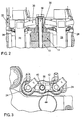
- FIGS. 2 and 3 A second, alternative embodiment is in FIGS. 2 and 3 shown. Functionally identical parts are denoted by the same reference numerals as in Fig. 1 so that their explanation to the above description of Fig. 1 is referenced.
- Fig. 2 realized the screwing of the clamping claw 30 with a through-bolt 36 instead of the above-described bolt solution.
- the system threaded bolt 12 with two nuts 18, 34 ( Fig. 1 ) replaced by a M8 combi screw 36.
- a slowly hardening sealant is then preferably used, since the time until the necessary bolt force is applied is longer than in the solution described above Fig. 1 , For the tolerance situation on the screw side results in an improvement, since the M8 nut 18 is omitted for attachment of the lead frame 14.
- the cylinder head 10 is provided in the preassembled state with attached and bolted cylinder head cover 20.
- the lead frame 14 is bolted and sealed.
- each 2 fuel injectors 24 are pre-assembled with a clamping claw 30 and threaded through the two injector sealing rings 26 in the cylinder head 10.
- the fuel injectors 24 are inserted into the seat 32 in the cylinder head 10 (in FIGS. 2 and 3 not shown) pressed.
- the fastening screw 36 is inserted through the clamping claw 30 in the cylinder head 10 and bolted with 10Nm and 90 ° further rotation.
- the fuel injectors 24 are now mounted.
- a stiff clamping claw 30 is used, which allows only a small deflection
- the power flow through the screw 36 thus goes on the one hand directly into the cylinder head 10 and on the other hand directly to the fuel injectors 24.
- the screw 36 is for example an M6 screw, both can be designed with a washer as well as a one-piece screw.
- the screw 36 has a sealing shank which seals the screw over the cylinder head cover 20.
- a sealing rubber 38 is mounted in the cylinder head cover 20. This rubber seal 38 is either molded or mounted.
- the seat of the screw 36 on the clamping claw 30 is designed such that on the clamping claw 30 has a conical contour and on the screw 36 is formed a spherical contour. Thus, a line load is applied even when tilted the clamping claw 30 or the screw 36. This ensures a uniform load distribution.
- the clamping claw 30 is not tightened in this case to block. Under the prescribed torque and the further rotation angle, the specified strength of the screw 36 results in a resulting minimum preload force, which depends on the coefficients of friction and the strength tolerances of the screw connection.
- the screw 36 is limited in this case in its strength and is subject to plastic deformation.
- An advantage of this system is the reusability of the clamping claw 30. Only the screw 36 must be exchanged after a removal and reinstallation of the fuel injectors 24, for example, if a repair on the injector o.ä. necessary is.
- Another advantage is that the assembly of the cylinder head 10 prior to assembly of the fuel injectors 24 may be more complete than in the first embodiment according to FIG Fig. 1 , Furthermore, the tolerance situation is improved because of the smaller number of components. Due to the very stiff clamping claw 30, the introduction of lateral forces in the fuel injectors 24 is greatly reduced. In the geometry of the clamping claw 30 is now mainly on maximum rigidity.
- the clamping claw 30 is formed in three parts and comprises two clamping brackets 42, 44, each forming one side of the two arms of the clamping claw 30, and a central part, clip piece or clamping member 40 in the middle of the clamping claw 30 for receiving the screw 36 and for guiding the clamping bracket 42.
- the system is loosely mounted and is held together by the screw forces or it is slightly prefixed by clamping.
- the advantage of this system is that the clamping claw 30 can be disassembled without pulling both fuel injectors 24. For this purpose, one disassembles the clamping claw 30 and then only pulls out the fuel injector 24 to be repaired from the cylinder head 10. Another advantage is the more cost-effective production of the individual parts.
Landscapes
- Engineering & Computer Science (AREA)
- Chemical & Material Sciences (AREA)
- Combustion & Propulsion (AREA)
- Mechanical Engineering (AREA)
- General Engineering & Computer Science (AREA)
- Fuel-Injection Apparatus (AREA)
- Cylinder Crankcases Of Internal Combustion Engines (AREA)
Abstract
Description
- Die Erfindung betrifft eine Brennkraftmaschine, insbesondere Dieselmotor, insbesondere eines Kraftfahrzeugs, mit wenigstens zwei Arbeitszylindern und einem die Arbeitszylinder verschließenden Zylinderkopf, in dem für jeden Arbeitszylinder eine Kraftstoffeinspritzvorrichtung angeordnet ist, wobei für je wenigstens zwei Kraftstoffeinspritzvorrichtungen eine Spannpratze mit wenigstens zwei Armen derart vorgesehen ist, dass jeweils ein Arm der Spannpratze auf eine Kraftstoffeinspritzvorrichtung wirkt und die jeweilige Kraftstoffeinspritzvorrichtung mit einer vorbestimmten Kraft gegen einen Sitz im Zylinderkopf drückt, wobei ein Befestigungsmittel vorgesehen ist, welches die Spannpratze am Zylinderkopf befestigt, gemäß dem Oberbegriff des Patentanspruchs 1.
- Aus der
EP 0 751 290 B1 ist eine Anordnung zum Festklemmen von zwei oder drei Kraftstoffeinspritzdüsen mit einer Düsenklemmeinrichtung bekannt. Hierbei weist die Düsenklemmeinrichtung Kontaktteile auf, die auf Klemmaufnahmesitzen der Kraftstoffeinspritzdüsen aufsitzen. Zwischen den Kontaktteilen weist die Düsenklemmeinrichtung ein Bolzeneinsatzloch auf, in das ein Klemmbolzen eingeführt ist, um einen Druck gegen die Kraftstoffeinspritzdüsen auszuüben und Abdichtlasten abzugeben. Die Düsenklemmeinrichtung beinhaltet ein Spiel, welches die Druckkraft auf die Kraftstoffeinspritzdüsen verringert, so dass bei einem vorbestimmten Grad an Bolzenanziehkraft eine im Wesentlichen gleiche Druckkraft auf den drei Kraftstoffeinspritzdüsen auftritt. Alternativ ist die Düsenklemmeinrichtung aus einem Federmaterial derart hergestellt, dass die Düsenklemmeinrichtung leicht gebogen wird. - Der Erfindung liegt die Aufgabe zugrunde, eine Brennkraftmaschine der o.g. Art hinsichtlich Montage und Wartungsfreundlichkeit zu verbessern.
- Diese Aufgabe wird erfindungsgemäß durch eine Brennkraftmaschine der o.g. Art mit den in Anspruch 1 gekennzeichneten Merkmalen gelöst. Vorteilhafte Ausgestaltungen der Erfindung sind in den weiteren Ansprüchen beschrieben.
- Dazu ist es bei einer Brennkraftmaschine der o.g. Art erfindungsgemäß vorgesehen, dass die Arme der Spannpratze und/oder das Befestigungsmittel derart ausgebildet ist bzw. sind, dass oberhalb der vorbestimmten Kraft für den Andruck der Kraftstoffeinspritzvorrichtungen gegen den jeweiligen Sitz im Zylinderkopf die Arme der Spannpratze und/oder das Befestigungsmittel einer plastischen Verformung unterliegen.
- Dies hat den Vorteil, dass auf einfache Weise eine vorbestimmte Andruckkraft der Kraftstoffeinspritzvorrichtungen gegen den jeweiligen Sitz im Zylinderkopf sichergestellt und eine Beschädigung der Kraftstoffeinspritzvorrichtungen bei der Montage durch eine zu hohe Andruckkraft wirksam vermieden ist.
- In einer bevorzugten Ausführungsform umfasst das Befestigungsmittel für wenigstens eine Spannpratze wenigstens einen Schraubbolzen, welcher in den Zylinderkopf eingeschraubt ist und durch die Spannpratze hindurch greift, wobei eine Schraubenmutter vorgesehen ist, welche auf den Schraubbolzen aufgeschraubt die Spannpratze in Richtung des Zylinderkopfes derart mit Kraft beaufschlagt, dass die Spannpratze die Kraftstoffeinspritzvorrichtung gegen den jeweiligen Sitz im Zylinderkopf drückt.
- Zweckmäßigerweise umfasst das Befestigungsmittel für wenigstens eine Spannpratze wenigstens eine Durchsteckschraube mit Schraubenkopf, welche durch die Spannpratze hindurch greift und in den Zylinderkopf geschraubt ist, so dass der Schraubenkopf die Spannpratze in Richtung des Zylinderkopfes derart mit Kraft beaufschlagt, dass die Spannpratze die Kraftstoffeinspritzvorrichtung gegen den jeweiligen Sitz im Zylinderkopf drückt.
- Dadurch, dass die Spannpratze dreiteilig ausgebildet ist und zwei Spannbügel, die jeweils eine Seite der beiden Arme der Spannpratze ausbilden, sowie ein Klammerstück aufweist, welches die beiden Spannbügel zusammenhält und durch welches das Befestigungsmittel greift, müssen bei Wartungs- oder Reparaturarbeiten an den Kraftstoffeinspritzvorrichtungen nach dem Lösen der Befestigungsmittel nicht die vollständigen Spannpratzen sondern nur die Spannbügel ausgetauscht werden.
- Zweckmäßigerweise sind die Spannbügel als Blechstanzteile und/oder das Klammerstück als Blechteil, Gussteil oder Sinterteil ausgebildet.
- Die Erfindung wird im Folgenden anhand der Zeichnung näher erläutert. Diese zeigt in
- Fig.1
- eine erste bevorzugte Ausführungsform einer erfindungsgemäßen Brennkraftmaschine in Schnittansicht,
- Fig. 2
- eine zweite bevorzugte Ausführungsform einer erfindungsgemäßen Brennkraftmaschine in Schnittansicht und
- Fig. 3
- die zweite bevorzugte Ausführungsform einer erfindungsgemäßen Brennkraftmaschine gemäß
Fig. 2 in Aufsicht. - Die Erfindung umfasst eine Befestigung und Abdichtung von beispielsweise CR(Common-Rail)-Injektoren in einem Zylinderkopf einer Brennkraftmaschine. Erfindungsgemäß ist immer eine Spannpratze zur Befestigung von je 2 Injektoren mit einer Befestigungsschraube vorgesehen. Die Verschraubung erfolgt immer im Zylinderkopf. Hierbei muss die Vorspannkraft auf die Injektoren genau eingestellt werden, da es sonst zu Beschädigungen im Injektor oder zu Undichtigkeiten kommen kann. Das System muss also immer eine minimale Vorspannkraft darstellen, mit der die beiden Injektoren sicher abgedichtet werden können. Außerdem muss die Vorspannkraft nach oben begrenzt werden, damit die Injektoren nicht zerstört werden.
- Bei der in
Fig. 1 dargestellten, ersten bevorzugten Ausführungsform ist in den Zylinderkopf 10 zwischen je 2 Zylindern ein beispielsweise M8-Gewindebolzen 12 eingeschraubt. Der Gewindebolzen 12 ist bis auf den Bohrungsgrund eingeschraubt. Anschließend wird ein Leiterrahmen 14 mit Flüssigdichtmittel aufgesetzt.und mit beispielsweise M6-Kombischrauben 16 verschraubt. Dabei werden Lagerbrücken (Verbindungsstege zwischen Ein- und Auslassnockenwellenlager) im Bereich der M8-Gewindebolzen 12 mit einer beispielsweise M8-Schraubmutter 18 verschraubt. An den Stegen, an denen keine Schraubbolzen vorhanden sind, werden die Stege mit beispielsweise 2xM6-Kombischrauben (nicht dargestellt) befestigt. Alternativ kann an diesen Stellen eine Substitution von 2xM6-Kombischraube durch 1xM8-Kombischraube vorgesehen sein. - Anschließend wird eine Zylinderkopfhaube 20 verbaut. Im Bereich der Gewindebolzen 12 sind in der Zylinderkopfhaube 20 metallische Stützhülsen 22 eingebracht (eingespritzt oder eingeschlagen). Diese Stützhülsen 22 sitzen lose auf der schon montierten M8-Schraubmutter 18 auf. An der Zylinderkopfhaube 20 ist im Bereich von Kraftstoffinjektoren 24 je ein Dichtring 26 montiert und im Bereich des Gewindebolzens 12 ist eine Dichtung 28 zum Leiterrahmen integriert. Anschließend werden je 2 Kraftstoffinjektoren 24 mit einer Spannpratze 30 zusammengesteckt und gemeinsam durch die beiden Dichtringe 26 in der Zylinderkopfhaube 20 in den Zylinderkopf 10 gesteckt. Die Spannpratze 30 wird über ein Durchgangsloch auf den Gewindebolzen 12 aufgefädelt. Das System aus Kraftstoffinjektoren 24 und Spannpratze 30 wird gegen einen Dichtsitz 32 in einer Injektorbohrung des Zylinderkopfes 10 gedrückt. Anschließend wird der Verbund mit einer weiteren beispielsweise M8-Schraubmutter 34 verschraubt. Die Spannpratze 30 wird durch das angelegte Drehmoment von beispielsweise 20Nm und einem Weiterdrehwinkel von 90° auf Block verschraubt. Der Kraftfluss im Bereich der Gewindebolzen 12 läuft also über die äußere M8-Schraubmutter 34 durch die Spannpratze 30, die Hülse 22, die weitere M8-Schraubmutter 18 und den Leiterrahmen 14 in den Zylinderkopf 10. Auf der Seite des Kraftstoffinjektors 24 wird die Kraft durch die M8-Schraubmutter 34 und über die beiden Arme der Spannpratze 30 auf den Kraftstoffinjektor 24 und dann auf eine Dichtscheibe des Kraftstoffinjektors 24 im Kopf geleitet.
- Durch das Verschrauben der Spannpratze 30 auf Block wird auch die notwendige Anpresskraft für die Dichtung 28 in der Zylinderkopfhaube 20 auf den Leiterrahmen 14 im Bereich der Gewindebolzen 12 aufgebracht.
- Die Festigkeit der M8-Verschraubung ist derart ausgelegt, dass unter allen Toleranzbedingungen immer eine Verschraubung auf Block möglich ist. Dies ist wichtig, damit der Dichtverbund umfassend Zylinderkopfhaube 20 und Leiterrahmen 14 funktioniert und damit es nicht zu Relativbewegungen zwischen der Spannpratze 30 und den Kraftstoffinjektoren 24 sowie zwischen der Spannpratze 30 und der Hülse 22 kommen kann. Die Toleranzen setzen sich auf der Seite der Kraftstoffinjektoren 24 aus den Höhentoleranzen der Auflageflächen der Spannpratze 30 an den Kraftstoffinjektoren 24 zusammen und betragen bis zu 1,1 mm. Im Bereich der Aufläge der Spannpratze 30 auf der Hülse 22 setzten sich die Toleranzen aus Spannpratze 30, Hülse 22, Leiterrahmen 14 und Zylinderkopf 10 zusammen. Hier können sich ebenfalls Toleranzen im Bereich von 1,2 mm ergeben. Als minimaler Verformungsweg wird nun ein Abstand "X" zwischen Spannpratze 30 und Hülse 22 ausgelegt und eingestellt.
- Für eine minimale Vorspannkraft von beispielsweise 7kN ist der Fall "kleinster Verformungsweg" der Spannpratze 30 bis zum Blocksitz relevant. Das bedeutet, dass die Spannpratze 30 schon bei kleinen Verformungswegen eine ausreichende Steifigkeit haben muss, um die geforderten Vorspannkräfte zu erreichen. Bei "großen Verformungswegen" bis zum Blocksitz bei entgegengesetzter Toleranzlage ist die Spannpratze 30 derart ausgelegt, dass es zu einer plastischen Verformung in der Spannpratze 30 kommt und somit kein weiterer Zuwachs an Vorspannkraft auf den Kraftstoffinjektor 24 oberhalb des maximal zulässigen Wertes von 9kN pro Kraftstoffinjektor 24 möglich ist. Der minimale Verformungsweg ist also abhängig von den Toleranzen der beteiligten Bauteile und dem gewählten Abstand "x" zwischen Spannpratze 30 und Hülse 22. Der Abstand "x" ergibt sich nun aus den Toleranzen und einem minimal notwendigen Verformungsweg der plastischen Verformung der Arme der Spannpratzen 30 für das Erreichen der minimalen Vorspannkraft.
- Da die zulässigen Kräfte auf die Kraftstoffinjektoren 24 bekannt sind, ist eine Kombination aus Pratzengeometrie, Materialeigenschaften und Abstand "x" als Lösungsweg vorgesehen. Die Spannpratze 30 ist derart ausgelegt, dass eine plastische Verformung immer in den Armen der Spannpratze 30 erfolgt. Der mittlere Bereich der Spannpratze 30 mit der Durchgangsbohrung und der Mutternauflage oben und der Hülsenauflage unten sind sehr steif gehalten. Dadurch ist sichergestellt, dass die Auflageflächen keiner Verformung unterworfen sind und es so nicht zu Kantenträgern und Vorspannkraftverlusten kommt.
- Die Arme der Spannpratze 30 sind derart ausgelegt, dass sämtliche Verformungen dort stattfinden. Der Querschnitt der Arme verringert sich im Horizontalschnitt bis zu den Auflageflächen der Spannpratze 30 in Abhängigkeit von der Materialsteifigkeit und der daraus resultierenden Biegebelastung bei anliegender Last durch den Schraubfall. Die Breite der Arme ist konstant gehalten. Hierbei ist der Querschnitt derart gewählt, dass die minimale Vorspannkraft sicher erreicht wird und die maximal zulässige Biegespannung beim Übergang der Arme in aufliegende Füßchen nicht überschritten wird. Aus dem Zusammenspiel zwischen Geometrie und Materialeigenschaften lassen sich nun unterschiedliche Varianten von Spannpratzen 30 erzeugen. Das hat den Vorteil, dass man für beengte Platzverhältnisse steifere Materialien wählt, die mit geringeren Querschnitten auskommen. Bei genügend Bauraum hingegen werden kostengünstigere Materialien gewählt, wobei sich hierbei größere Querschnitte in den Armen der Spannpratze 30 ergeben. Der Abstand "x" ist eine Variable, die zur Optimierung herangezogen werden kann.
- Eine zweite, alternative Ausführungsform ist in
Fig. 2 und 3 dargestellt. Funktionsgleiche Teile sind mit gleichen Bezugszeichen bezeichnet, wie inFig. 1 , so dass zu deren Erläuterung auf die obige Beschreibung derFig. 1 verwiesen wird. Im Unterschied zur ersten Ausführungsform gemäßFig. 1 ist bei der zweiten Ausführungsform gemäßFig. 2 die Verschraubung der Spannpratze 30 mit einer Durchsteckschraube 36 anstelle der oben beschriebenen Bolzenlösung realisiert. Hierbei wird das System Gewindebolzen 12 mit zwei Schraubmuttern 18, 34 (Fig. 1 ) durch eine M8-Kombischraube 36 ersetzt. Für die Verschraubung der Spannpratze 30 und deren Kraftbeaufschlagen bei den Kraftstoffinjektoren 24 ergeben sich keine weiteren Auswirkungen. Für die Abdichtung des Leiterrahmens 14 zum Zylinderkopf 10 wird dann bevorzugt ein langsam aushärtendes Dichtmittel verwendet, da die Zeit, bis die notwendige Schraubenkraft anliegt, länger ist als in der oben beschriebenen Lösung gemäßFig. 1 . Für die Toleranzsituation auf der Schraubenseite ergibt sich eine Verbesserung, da die M8-Schraubutter 18 zur Befestigung der Leiterrahmens 14 entfällt. - Nachfolgend wird der Zusammenbau der zweiten bevorzugten Ausführungsform gemäß
Fig. 2 beschrieben. Der Zylinderkopf 10 wird in vormontierten Zustand mit aufgesetzter und verschraubter Zylinderkopfhaube 20 bereitgestellt. Der Leiterrahmen 14 ist verschraubt und abgedichtet. Nun werden je 2 Kraftstoffinjektoren 24 mit einer Spannpratze 30 vormontiert und durch die beiden Injektordichtringe 26 in den Zylinderkopf 10 eingefädelt. Dann werden die Kraftstoffinjektoren 24 in den Sitz 32 im Zylinderkopf 10 (inFig. 2 und 3 nicht dargestellt) gedrückt. Die Befestigungsschraube 36 wird durch die Spannpratze 30 in den Zylinderkopf 10 gesteckt und mit 10Nm und 90° Weiterdrehwinkel verschraubt. Die Kraftstoffinjektoren 24 sind nun montiert. - Bei diesem System wird eine steife Spannpratze 30 eingesetzt, die nur eine geringe Durchbiegung zulässt Der Kraftfluss über die Schraube 36 geht also einerseits direkt in den Zylinderkopf 10 und andererseits direkt auf die Kraftstoffinjektoren 24. Die Schraube 36 ist beispielsweise eine M6-Schraube, die sowohl mit Unterlegscheibe als auch als einteilige Schraube ausgeführt sein kann.
- Die Schraube 36 weist einen Dichtschaft auf, der die Schraube über die Zylinderkopfhaube 20 abdichtet. Dazu ist in der Zylinderkopfhaube 20 ein Dichtgummi 38 montiert. Dieser Dichtgummi 38 ist entweder angespritzt oder montiert. Der Sitz der Schraube 36 auf der Spannpratze 30 ist derart ausgeführt, dass auf der Spannpratze 30 eine kegelförmige Kontur und auf der Schraube 36 eine kugelförmige Kontur ausgebildet ist. Somit wird auch bei Schrägstellung der Spannpratze 30 oder der Schraube 36 eine Linienlast aufgetragen. Damit ist eine gleichmäßige Lastverteilung sichergestellt.
- Die Spannpratze 30 wird in diesem Fall nicht auf Block angezogen. Unter dem vorgeschriebenen Drehmoment und dem Weiterdrehwinkel ergibt sich aus der festgelegten Festigkeit der Schraube 36 eine resultierende minimale Vorspannkraft, die von den Reibbeiwerten und den Festigkeitstoleranzen der Schraubenverbindung abhängig ist. Die Schraube 36 ist für diesen Fall in ihrer Festigkeit eingeschränkt und unterliegt einer plastischen Verformung. Ein Vorteil dieses Systems ist die Wiederverwendbarkeit der Spannpratze 30. Lediglich die Schraube 36 muss nach einem Aus- und wieder Einbau der Kraftstoffinjektoren 24 getauscht werden, beispielsweise wenn eine Reparatur am Injektor o.ä. notwendig ist. Ein weiterer Vorteil liegt darin, dass der Zusammenbau des Zylinderkopfes 10 vor der Montage der Kraftstoffinjektoren 24 vollständiger sein kann als bei der ersten Ausführungsform gemäß
Fig. 1 . Weiterhin ist die Toleranzsituation wegen der geringeren Anzahl der Bauteile verbessert. Durch die sehr steife Spannpratze 30 wird die Einleitung von Querkräften in die Kraftstoffinjektoren 24 stark reduziert. Bei der Geometriegebung der Spannpratze 30 kommt es nun hauptsächlich auf maximale Steifigkeit an. - Aus
Fig. 3 ist zusätzlich eine besondere Ausführungsform der Spannpratze 30 ersichtlich Unabhängig vom Verschraubungskonzept gemäßFig. 1 oderFig. 2 ist die Spannpratze 30 beispielsweise dreiteilig ausgebildet und umfasst zwei Spannbügel 42, 44, die jeweils eine Seite der beiden Arme der Spannpratze 30 ausbilden, und ein Zentralteil, Klammerstück oder Klemmteil 40 in der Mitte der Spannpratze 30 zur Aufnahmen der Schraube 36 und zur Führung der Spannbügel 42. Das System ist lose montiert und wird durch die Schraubenkräfte zusammengehalten oder es ist durch Klemmen leicht vorfixiert. Der Vorteil dieses Systems liegt darin, dass die Spannpratze 30 ohne Ziehen beider Kraftstoffinjektoren 24 demontiert werden kann. Hierzu baut man die Spannpratze 30 auseinander und zieht dann nur den zu reparierenden Kraftstoffinjektor 24 aus dem Zylinderkopf 10 heraus. Ein weiter Vorteil ist die kostengünstigere Herstellung der Einzelteile. -
- 10
- Zylinderkopf
- 12
- Gewindebolzen
- 14
- Leiterrahmen
- 16
- M6-Kombischrauben
- 18
- Schraubmutter
- 20
- Zylinderkopfhaube
- 22
- metallische Stützhülsen
- 24
- Kraftstoffinjektor
- 26
- Dichtring
- 28
- Dichtung zum Leiterrahmen
- 30
- Spannpratze
- 32
- Dichtsitz
- 34
- Schraubmutter
- 36
- Durchsteckschraube
- 38
- Dichtgummi
- 40
- Klemmteil
- 42
- Spannbügel
- 44
- Spannbügel
Claims (6)
- Brennkraftmaschine, insbesondere Dieselmotor, insbesondere eines Kraftfahrzeugs, mit wenigstens zwei Arbeitszylindern und einem die Arbeitszylinder verschließenden Zylinderkopf (10), in dem für jeden Arbeitszylinder eine Kraftstoffeinspritzvorrichtung (24) angeordnet ist, wobei für je wenigstens zwei Kraftstoffeinspritzvorrichtungen (24) eine Spannpratze (30) mit wenigstens zwei Armen derart vorgesehen ist, dass jeweils ein Arm der Spannpratze (30) auf eine Kraftstoffeinspritzvorrichtung (24) wirkt und die jeweilige Kraftstoffeinspritzvorrichtung (24) mit einer vorbestimmten Kraft gegen einen Sitz (32) im Zylinderkopf (10) drückt, wobei ein Befestigungsmittel (12; 36) vorgesehen ist, welches die Spannpratze (30) am Zylinderkopf (10) befestigt, dadurch gekennzeichnet, dass die Arme der Spannpratze (30) und/oder das Befestigungsmittel (12; 36) derart ausgebildet ist bzw. sind, dass oberhalb der vorbestimmten Kraft für den Andruck der Kraftstoffeinspritzvorrichtungen (24) gegen den jeweiligen Sitz (32) im Zylinderkopf (10) die Arme der Spannpratze (30) und/oder das Befestigungsmittel (12; 36) einer plastischen Verformung unterliegen.
- Brennkraftmaschine nach Anspruch 1, dadurch gekennzeichnet, dass das Befestigungsmittel für wenigstens eine Spannpratze (30) wenigstens einen Schraubbolzen (12) umfasst, welcher in den Zylinderkopf (10) eingeschraubt ist und durch die Spannpratze (30) hindurch greift, wobei eine Schraubenmutter (34) vorgesehen ist, welche auf den Schraubbolzen (12) aufgeschraubt die Spannpratze (30) in Richtung des Zylinderkopfes (10) derart mit Kraft beaufschlagt, dass die Spannpratze (30) die Kraftstoffeinspritzvorrichtungen (24) gegen den jeweiligen Sitz (32) im Zylinderkopf (10) drückt.
- Brennkraftmaschine nach wenigstens einem der vorhergehenden Ansprüche, dadurch gekennzeichnet, dass das Befestigungsmittel für wenigstens eine Spannpratze (30) wenigstens eine Durchsteckschraube (36) mit Schraubenkopf umfasst, welche durch die Spannpratze (30) hindurch greift und in den Zylinderkopf (10) geschraubt ist, so dass der Schraubenkopf die Spannpratze (30) in Richtung des Zylinderkopfes (10) derart mit Kraft beaufschlagt, dass die Spannpratze (30) die Kraftstoffeinspritzvorrichtungen (24) gegen den jeweiligen Sitz (32) im Zylinderkopf drückt.
- Brennkraftmaschine nach wenlgstens einem der vorhergehenden Ansprüche, dadurch gekennzeichnet, dass die Spannpratze (30) dreiteilig ausgebildet ist und zwei Spannbügel (42, 44), die jeweils eine Seite der beiden Arme der Spannpratze (30) ausbilden, sowie ein Klammerstück (40) aufweist, welches die beiden Spannbügel (42, 44) zusammenhält und durch welches das Befestigungsmittel (12; 36) greift.
- Brennkraftmaschine nach Anspruch 4, dadurch gekennzeichnet, dass die Spannbügel (42, 44) als Blechstanzteile ausgebildet sind.
- Brennkraftmaschine nach Anspruch 4 oder 5, dadurch gekennzeichnet, dass das Klammerstück (40) als Blechteil, Gussteil oder Sinterteil ausgebildet ist.
Applications Claiming Priority (1)
| Application Number | Priority Date | Filing Date | Title |
|---|---|---|---|
| DE200710050512 DE102007050512A1 (de) | 2007-10-23 | 2007-10-23 | Brennkraftmaschine mit Kraftstoffinjektoren |
Publications (3)
| Publication Number | Publication Date |
|---|---|
| EP2053235A2 true EP2053235A2 (de) | 2009-04-29 |
| EP2053235A3 EP2053235A3 (de) | 2009-11-04 |
| EP2053235B1 EP2053235B1 (de) | 2016-12-14 |
Family
ID=40219987
Family Applications (1)
| Application Number | Title | Priority Date | Filing Date |
|---|---|---|---|
| EP08017534.2A Not-in-force EP2053235B1 (de) | 2007-10-23 | 2008-10-07 | Brennkraftmaschine mit Kraftstoffinjektoren |
Country Status (2)
| Country | Link |
|---|---|
| EP (1) | EP2053235B1 (de) |
| DE (1) | DE102007050512A1 (de) |
Cited By (1)
| Publication number | Priority date | Publication date | Assignee | Title |
|---|---|---|---|---|
| US10041458B2 (en) | 2016-01-19 | 2018-08-07 | Perkins Engines Company Limited | Injector clamp |
Families Citing this family (2)
| Publication number | Priority date | Publication date | Assignee | Title |
|---|---|---|---|---|
| DE102008009385A1 (de) | 2008-02-14 | 2009-08-27 | Volkswagen Ag | Brennkraftmaschine |
| DE102020004625A1 (de) | 2020-07-30 | 2022-02-03 | Deutz Aktiengesellschaft | lnjektorverpratzung |
Citations (1)
| Publication number | Priority date | Publication date | Assignee | Title |
|---|---|---|---|---|
| EP0751290B1 (de) | 1995-06-26 | 2000-03-22 | Isuzu Motors Limited | Anordnung zum Festklemmen einer Kraftstoffeinspritzdüse |
Family Cites Families (4)
| Publication number | Priority date | Publication date | Assignee | Title |
|---|---|---|---|---|
| GB8728518D0 (en) * | 1987-12-05 | 1988-01-13 | Lucas Ind Plc | Clamping arrangement |
| FR2763379B1 (fr) * | 1997-05-16 | 1999-07-16 | Renault | Bride de fixation d'un injecteur |
| DE10155678A1 (de) * | 2001-11-13 | 2003-05-22 | Bosch Gmbh Robert | Einspannvorrichtung für ein Kraftstoffeinspritzventil |
| FR2884876B1 (fr) * | 2005-04-22 | 2007-08-03 | Peugeot Citroen Automobiles Sa | Dispositif de fixation pour le montage d'un porte-injecteur sur un moteur a combustion interne et moteur a combustion interne comprenant un tel dispositif |
-
2007
- 2007-10-23 DE DE200710050512 patent/DE102007050512A1/de not_active Withdrawn
-
2008
- 2008-10-07 EP EP08017534.2A patent/EP2053235B1/de not_active Not-in-force
Patent Citations (1)
| Publication number | Priority date | Publication date | Assignee | Title |
|---|---|---|---|---|
| EP0751290B1 (de) | 1995-06-26 | 2000-03-22 | Isuzu Motors Limited | Anordnung zum Festklemmen einer Kraftstoffeinspritzdüse |
Cited By (1)
| Publication number | Priority date | Publication date | Assignee | Title |
|---|---|---|---|---|
| US10041458B2 (en) | 2016-01-19 | 2018-08-07 | Perkins Engines Company Limited | Injector clamp |
Also Published As
| Publication number | Publication date |
|---|---|
| EP2053235B1 (de) | 2016-12-14 |
| DE102007050512A1 (de) | 2009-04-30 |
| EP2053235A3 (de) | 2009-11-04 |
Similar Documents
| Publication | Publication Date | Title |
|---|---|---|
| EP2189650B1 (de) | Brennstoffeinspritzvorrichtung | |
| EP2176539B1 (de) | Brennstoff-einspritzanlage mit ausgleichselement | |
| DE102012105402B4 (de) | Verstellvorrichtung für einen Abgasturbolader | |
| EP1888912B1 (de) | Anschluss-system | |
| DE19920822A1 (de) | Anordnung zur Befestigung eines Abgaskrümmers am Zylinderkopf einer Brennkraftmaschine | |
| EP2640956B1 (de) | Befestigungsanordnung einer kraftstoffzufuhrvorrichtung an einer verbrennungskraftmaschine | |
| WO2017182374A1 (de) | Kombination, umfassend ein gehäuse und einen flansch, und anordnung | |
| EP2587036B1 (de) | Brennkraftmaschine | |
| EP2053235B1 (de) | Brennkraftmaschine mit Kraftstoffinjektoren | |
| EP1315901A1 (de) | Spannelement für ein brennstoffeinspritzventil und brennstoffeinspritzanlage | |
| WO2011113790A1 (de) | Brennkraftmaschine mit einer verbindungsanordnung für einen zylinderkopf | |
| DE102009014399B3 (de) | Kraftstoffverteiler mit Halterung | |
| DE102014108163A1 (de) | Kraftstoffverteiler | |
| EP1698778B1 (de) | Zylinderkopf für eine direkteinspritzende Brennkraftmaschine mit einem Niederhalter für zwei Einspritzventile | |
| DE102005014217B4 (de) | Befestigungsvorrichtung für eine Dachreling | |
| EP1310669A2 (de) | Kraftstoffinjektor mit vereinfachter Montage durch ungeteilten Ventildeckel | |
| EP3203048B1 (de) | Befestigungsanordnung zur festlegung eines auslasskrümmers an einem zylinderkopf einer brennkraftmaschine | |
| AT4632U1 (de) | Einspritzsystem für eine brennkraftmaschine | |
| DE102016115709B4 (de) | Befestigungsvorrichtung | |
| DE102004036518B4 (de) | Verdrehsichere Dichtkegelverbindung bei Einspritzleitungen zur Kraftstoffeinspritzung und Verfahren zu deren Herstellung | |
| WO2019025059A1 (de) | Brennstoffeinspritzventil | |
| DE10343149B4 (de) | Befestigungsanordnung für einen Auslasskrümmer einer Verbrennungskraftmaschine sowie Montageverfahren hierfür | |
| EP3658756B1 (de) | Befestigungsmutter sowie verbrennungsmotor mit befestigungsmutter | |
| DE102011087687B4 (de) | Befestigungseinrichtung für ein Bauteil an einem Gehäuseblock mittels Bajonett | |
| WO2002075169A1 (de) | Befestigungsvorrichtung an einem trägerblech |
Legal Events
| Date | Code | Title | Description |
|---|---|---|---|
| PUAI | Public reference made under article 153(3) epc to a published international application that has entered the european phase |
Free format text: ORIGINAL CODE: 0009012 |
|
| AK | Designated contracting states |
Kind code of ref document: A2 Designated state(s): AT BE BG CH CY CZ DE DK EE ES FI FR GB GR HR HU IE IS IT LI LT LU LV MC MT NL NO PL PT RO SE SI SK TR |
|
| AX | Request for extension of the european patent |
Extension state: AL BA MK RS |
|
| PUAL | Search report despatched |
Free format text: ORIGINAL CODE: 0009013 |
|
| AK | Designated contracting states |
Kind code of ref document: A3 Designated state(s): AT BE BG CH CY CZ DE DK EE ES FI FR GB GR HR HU IE IS IT LI LT LU LV MC MT NL NO PL PT RO SE SI SK TR |
|
| AX | Request for extension of the european patent |
Extension state: AL BA MK RS |
|
| 17P | Request for examination filed |
Effective date: 20100504 |
|
| 17Q | First examination report despatched |
Effective date: 20100610 |
|
| AKX | Designation fees paid |
Designated state(s): AT BE BG CH CY CZ DE DK EE ES FI FR GB GR HR HU IE IS IT LI LT LU LV MC MT NL NO PL PT RO SE SI SK TR |
|
| RAP1 | Party data changed (applicant data changed or rights of an application transferred) |
Owner name: VOLKSWAGEN AKTIENGESELLSCHAFT |
|
| GRAP | Despatch of communication of intention to grant a patent |
Free format text: ORIGINAL CODE: EPIDOSNIGR1 |
|
| INTG | Intention to grant announced |
Effective date: 20160608 |
|
| GRAS | Grant fee paid |
Free format text: ORIGINAL CODE: EPIDOSNIGR3 |
|
| GRAA | (expected) grant |
Free format text: ORIGINAL CODE: 0009210 |
|
| AK | Designated contracting states |
Kind code of ref document: B1 Designated state(s): AT BE BG CH CY CZ DE DK EE ES FI FR GB GR HR HU IE IS IT LI LT LU LV MC MT NL NO PL PT RO SE SI SK TR |
|
| REG | Reference to a national code |
Ref country code: GB Ref legal event code: FG4D Free format text: NOT ENGLISH |
|
| REG | Reference to a national code |
Ref country code: CH Ref legal event code: EP |
|
| REG | Reference to a national code |
Ref country code: IE Ref legal event code: FG4D Free format text: LANGUAGE OF EP DOCUMENT: GERMAN |
|
| REG | Reference to a national code |
Ref country code: AT Ref legal event code: REF Ref document number: 853823 Country of ref document: AT Kind code of ref document: T Effective date: 20170115 |
|
| REG | Reference to a national code |
Ref country code: DE Ref legal event code: R096 Ref document number: 502008014876 Country of ref document: DE |
|
| PG25 | Lapsed in a contracting state [announced via postgrant information from national office to epo] |
Ref country code: LV Free format text: LAPSE BECAUSE OF FAILURE TO SUBMIT A TRANSLATION OF THE DESCRIPTION OR TO PAY THE FEE WITHIN THE PRESCRIBED TIME-LIMIT Effective date: 20161214 |
|
| REG | Reference to a national code |
Ref country code: LT Ref legal event code: MG4D |
|
| REG | Reference to a national code |
Ref country code: NL Ref legal event code: MP Effective date: 20161214 |
|
| PG25 | Lapsed in a contracting state [announced via postgrant information from national office to epo] |
Ref country code: SE Free format text: LAPSE BECAUSE OF FAILURE TO SUBMIT A TRANSLATION OF THE DESCRIPTION OR TO PAY THE FEE WITHIN THE PRESCRIBED TIME-LIMIT Effective date: 20161214 Ref country code: NO Free format text: LAPSE BECAUSE OF FAILURE TO SUBMIT A TRANSLATION OF THE DESCRIPTION OR TO PAY THE FEE WITHIN THE PRESCRIBED TIME-LIMIT Effective date: 20170314 Ref country code: LT Free format text: LAPSE BECAUSE OF FAILURE TO SUBMIT A TRANSLATION OF THE DESCRIPTION OR TO PAY THE FEE WITHIN THE PRESCRIBED TIME-LIMIT Effective date: 20161214 Ref country code: GR Free format text: LAPSE BECAUSE OF FAILURE TO SUBMIT A TRANSLATION OF THE DESCRIPTION OR TO PAY THE FEE WITHIN THE PRESCRIBED TIME-LIMIT Effective date: 20170315 |
|
| PG25 | Lapsed in a contracting state [announced via postgrant information from national office to epo] |
Ref country code: FI Free format text: LAPSE BECAUSE OF FAILURE TO SUBMIT A TRANSLATION OF THE DESCRIPTION OR TO PAY THE FEE WITHIN THE PRESCRIBED TIME-LIMIT Effective date: 20161214 Ref country code: HR Free format text: LAPSE BECAUSE OF FAILURE TO SUBMIT A TRANSLATION OF THE DESCRIPTION OR TO PAY THE FEE WITHIN THE PRESCRIBED TIME-LIMIT Effective date: 20161214 |
|
| PG25 | Lapsed in a contracting state [announced via postgrant information from national office to epo] |
Ref country code: NL Free format text: LAPSE BECAUSE OF FAILURE TO SUBMIT A TRANSLATION OF THE DESCRIPTION OR TO PAY THE FEE WITHIN THE PRESCRIBED TIME-LIMIT Effective date: 20161214 |
|
| PG25 | Lapsed in a contracting state [announced via postgrant information from national office to epo] |
Ref country code: SK Free format text: LAPSE BECAUSE OF FAILURE TO SUBMIT A TRANSLATION OF THE DESCRIPTION OR TO PAY THE FEE WITHIN THE PRESCRIBED TIME-LIMIT Effective date: 20161214 Ref country code: IS Free format text: LAPSE BECAUSE OF FAILURE TO SUBMIT A TRANSLATION OF THE DESCRIPTION OR TO PAY THE FEE WITHIN THE PRESCRIBED TIME-LIMIT Effective date: 20170414 Ref country code: EE Free format text: LAPSE BECAUSE OF FAILURE TO SUBMIT A TRANSLATION OF THE DESCRIPTION OR TO PAY THE FEE WITHIN THE PRESCRIBED TIME-LIMIT Effective date: 20161214 Ref country code: RO Free format text: LAPSE BECAUSE OF FAILURE TO SUBMIT A TRANSLATION OF THE DESCRIPTION OR TO PAY THE FEE WITHIN THE PRESCRIBED TIME-LIMIT Effective date: 20161214 Ref country code: CZ Free format text: LAPSE BECAUSE OF FAILURE TO SUBMIT A TRANSLATION OF THE DESCRIPTION OR TO PAY THE FEE WITHIN THE PRESCRIBED TIME-LIMIT Effective date: 20161214 |
|
| PG25 | Lapsed in a contracting state [announced via postgrant information from national office to epo] |
Ref country code: BG Free format text: LAPSE BECAUSE OF FAILURE TO SUBMIT A TRANSLATION OF THE DESCRIPTION OR TO PAY THE FEE WITHIN THE PRESCRIBED TIME-LIMIT Effective date: 20170314 Ref country code: IT Free format text: LAPSE BECAUSE OF FAILURE TO SUBMIT A TRANSLATION OF THE DESCRIPTION OR TO PAY THE FEE WITHIN THE PRESCRIBED TIME-LIMIT Effective date: 20161214 Ref country code: PT Free format text: LAPSE BECAUSE OF FAILURE TO SUBMIT A TRANSLATION OF THE DESCRIPTION OR TO PAY THE FEE WITHIN THE PRESCRIBED TIME-LIMIT Effective date: 20170414 Ref country code: ES Free format text: LAPSE BECAUSE OF FAILURE TO SUBMIT A TRANSLATION OF THE DESCRIPTION OR TO PAY THE FEE WITHIN THE PRESCRIBED TIME-LIMIT Effective date: 20161214 Ref country code: PL Free format text: LAPSE BECAUSE OF FAILURE TO SUBMIT A TRANSLATION OF THE DESCRIPTION OR TO PAY THE FEE WITHIN THE PRESCRIBED TIME-LIMIT Effective date: 20161214 |
|
| REG | Reference to a national code |
Ref country code: DE Ref legal event code: R097 Ref document number: 502008014876 Country of ref document: DE |
|
| PLBE | No opposition filed within time limit |
Free format text: ORIGINAL CODE: 0009261 |
|
| STAA | Information on the status of an ep patent application or granted ep patent |
Free format text: STATUS: NO OPPOSITION FILED WITHIN TIME LIMIT |
|
| REG | Reference to a national code |
Ref country code: FR Ref legal event code: PLFP Year of fee payment: 10 |
|
| 26N | No opposition filed |
Effective date: 20170915 |
|
| PG25 | Lapsed in a contracting state [announced via postgrant information from national office to epo] |
Ref country code: DK Free format text: LAPSE BECAUSE OF FAILURE TO SUBMIT A TRANSLATION OF THE DESCRIPTION OR TO PAY THE FEE WITHIN THE PRESCRIBED TIME-LIMIT Effective date: 20161214 |
|
| PG25 | Lapsed in a contracting state [announced via postgrant information from national office to epo] |
Ref country code: SI Free format text: LAPSE BECAUSE OF FAILURE TO SUBMIT A TRANSLATION OF THE DESCRIPTION OR TO PAY THE FEE WITHIN THE PRESCRIBED TIME-LIMIT Effective date: 20161214 |
|
| PG25 | Lapsed in a contracting state [announced via postgrant information from national office to epo] |
Ref country code: MC Free format text: LAPSE BECAUSE OF FAILURE TO SUBMIT A TRANSLATION OF THE DESCRIPTION OR TO PAY THE FEE WITHIN THE PRESCRIBED TIME-LIMIT Effective date: 20161214 |
|
| REG | Reference to a national code |
Ref country code: CH Ref legal event code: PL |
|
| REG | Reference to a national code |
Ref country code: IE Ref legal event code: MM4A |
|
| PG25 | Lapsed in a contracting state [announced via postgrant information from national office to epo] |
Ref country code: LI Free format text: LAPSE BECAUSE OF NON-PAYMENT OF DUE FEES Effective date: 20171031 Ref country code: CH Free format text: LAPSE BECAUSE OF NON-PAYMENT OF DUE FEES Effective date: 20171031 Ref country code: LU Free format text: LAPSE BECAUSE OF NON-PAYMENT OF DUE FEES Effective date: 20171007 |
|
| REG | Reference to a national code |
Ref country code: BE Ref legal event code: MM Effective date: 20171031 |
|
| PG25 | Lapsed in a contracting state [announced via postgrant information from national office to epo] |
Ref country code: BE Free format text: LAPSE BECAUSE OF NON-PAYMENT OF DUE FEES Effective date: 20171031 |
|
| PG25 | Lapsed in a contracting state [announced via postgrant information from national office to epo] |
Ref country code: MT Free format text: LAPSE BECAUSE OF FAILURE TO SUBMIT A TRANSLATION OF THE DESCRIPTION OR TO PAY THE FEE WITHIN THE PRESCRIBED TIME-LIMIT Effective date: 20161214 |
|
| REG | Reference to a national code |
Ref country code: FR Ref legal event code: PLFP Year of fee payment: 11 |
|
| PG25 | Lapsed in a contracting state [announced via postgrant information from national office to epo] |
Ref country code: IE Free format text: LAPSE BECAUSE OF NON-PAYMENT OF DUE FEES Effective date: 20171007 |
|
| REG | Reference to a national code |
Ref country code: AT Ref legal event code: MM01 Ref document number: 853823 Country of ref document: AT Kind code of ref document: T Effective date: 20171007 |
|
| PG25 | Lapsed in a contracting state [announced via postgrant information from national office to epo] |
Ref country code: AT Free format text: LAPSE BECAUSE OF NON-PAYMENT OF DUE FEES Effective date: 20171007 |
|
| PG25 | Lapsed in a contracting state [announced via postgrant information from national office to epo] |
Ref country code: HU Free format text: LAPSE BECAUSE OF FAILURE TO SUBMIT A TRANSLATION OF THE DESCRIPTION OR TO PAY THE FEE WITHIN THE PRESCRIBED TIME-LIMIT; INVALID AB INITIO Effective date: 20081007 |
|
| PG25 | Lapsed in a contracting state [announced via postgrant information from national office to epo] |
Ref country code: CY Free format text: LAPSE BECAUSE OF NON-PAYMENT OF DUE FEES Effective date: 20161214 |
|
| PG25 | Lapsed in a contracting state [announced via postgrant information from national office to epo] |
Ref country code: TR Free format text: LAPSE BECAUSE OF FAILURE TO SUBMIT A TRANSLATION OF THE DESCRIPTION OR TO PAY THE FEE WITHIN THE PRESCRIBED TIME-LIMIT Effective date: 20161214 |
|
| PGFP | Annual fee paid to national office [announced via postgrant information from national office to epo] |
Ref country code: FR Payment date: 20221024 Year of fee payment: 15 |
|
| PGFP | Annual fee paid to national office [announced via postgrant information from national office to epo] |
Ref country code: GB Payment date: 20221018 Year of fee payment: 15 Ref country code: DE Payment date: 20221031 Year of fee payment: 15 |
|
| P01 | Opt-out of the competence of the unified patent court (upc) registered |
Effective date: 20230523 |
|
| REG | Reference to a national code |
Ref country code: DE Ref legal event code: R119 Ref document number: 502008014876 Country of ref document: DE |
|
| GBPC | Gb: european patent ceased through non-payment of renewal fee |
Effective date: 20231007 |
|
| PG25 | Lapsed in a contracting state [announced via postgrant information from national office to epo] |
Ref country code: GB Free format text: LAPSE BECAUSE OF NON-PAYMENT OF DUE FEES Effective date: 20231007 |
|
| PG25 | Lapsed in a contracting state [announced via postgrant information from national office to epo] |
Ref country code: GB Free format text: LAPSE BECAUSE OF NON-PAYMENT OF DUE FEES Effective date: 20231007 Ref country code: FR Free format text: LAPSE BECAUSE OF NON-PAYMENT OF DUE FEES Effective date: 20231031 Ref country code: DE Free format text: LAPSE BECAUSE OF NON-PAYMENT OF DUE FEES Effective date: 20240501 |