EP2053155B1 - Laundry washing machine or washer-dryer comprising means for diverting the water flow - Google Patents
Laundry washing machine or washer-dryer comprising means for diverting the water flow Download PDFInfo
- Publication number
- EP2053155B1 EP2053155B1 EP08167486A EP08167486A EP2053155B1 EP 2053155 B1 EP2053155 B1 EP 2053155B1 EP 08167486 A EP08167486 A EP 08167486A EP 08167486 A EP08167486 A EP 08167486A EP 2053155 B1 EP2053155 B1 EP 2053155B1
- Authority
- EP
- European Patent Office
- Prior art keywords
- water
- washing
- water supply
- machine
- laundry
- Prior art date
- Legal status (The legal status is an assumption and is not a legal conclusion. Google has not performed a legal analysis and makes no representation as to the accuracy of the status listed.)
- Active
Links
- XLYOFNOQVPJJNP-UHFFFAOYSA-N water Substances O XLYOFNOQVPJJNP-UHFFFAOYSA-N 0.000 title claims abstract description 290
- 238000010412 laundry washing Methods 0.000 title claims 12
- 238000010438 heat treatment Methods 0.000 claims abstract description 18
- 238000001035 drying Methods 0.000 claims description 74
- 239000003599 detergent Substances 0.000 claims description 24
- 238000002347 injection Methods 0.000 claims description 7
- 239000007924 injection Substances 0.000 claims description 7
- 239000007788 liquid Substances 0.000 claims description 3
- 239000008399 tap water Substances 0.000 claims 8
- 235000020679 tap water Nutrition 0.000 claims 8
- 238000005406 washing Methods 0.000 abstract description 103
- 238000009833 condensation Methods 0.000 abstract description 12
- 230000005494 condensation Effects 0.000 abstract description 12
- 239000008400 supply water Substances 0.000 abstract description 9
- 238000007599 discharging Methods 0.000 abstract 1
- 101150114468 TUB1 gene Proteins 0.000 description 17
- 238000009423 ventilation Methods 0.000 description 15
- 238000011144 upstream manufacturing Methods 0.000 description 3
- 239000007844 bleaching agent Substances 0.000 description 2
- 238000012986 modification Methods 0.000 description 2
- 230000004048 modification Effects 0.000 description 2
- 230000001105 regulatory effect Effects 0.000 description 2
- 238000004078 waterproofing Methods 0.000 description 2
- 241000206607 Porphyra umbilicalis Species 0.000 description 1
- 238000001704 evaporation Methods 0.000 description 1
- 230000008020 evaporation Effects 0.000 description 1
- 230000007257 malfunction Effects 0.000 description 1
Images
Classifications
-
- D06F39/40—
-
- D—TEXTILES; PAPER
- D06—TREATMENT OF TEXTILES OR THE LIKE; LAUNDERING; FLEXIBLE MATERIALS NOT OTHERWISE PROVIDED FOR
- D06F—LAUNDERING, DRYING, IRONING, PRESSING OR FOLDING TEXTILE ARTICLES
- D06F39/00—Details of washing machines not specific to a single type of machines covered by groups D06F9/00 - D06F27/00
- D06F39/08—Liquid supply or discharge arrangements
- D06F39/088—Liquid supply arrangements
Definitions
- the present invention relates to a washing machine or a washing machine and drying laundry.
- this invention relates to laundry machines in which a wash cycle of a quantity of laundry is implemented, and washing-drying machines in which a wash cycle of a quantity of laundry is followed. a drying cycle of this laundry.
- Such a washing or washing and drying machine comprises a washing tub and a drum rotatably mounted about an axis of rotation in this tub.
- the axis of rotation can be horizontal or inclined.
- the document EP-A1- 1600545 discloses a washing machine comprising a body enclosing a washing tub filled from a mains water inlet, said machine comprising a mains water supply valve connected to a water supply conduit opening on a device for using water.
- the laundry to be washed is placed in the drum which has a perforated ferrule to allow the flow of water during the different phases of the laundry cycle.
- the washing and drying machines include a drying ventilation circuit.
- This drying air circuit generally comprises an air circulation duct in communication with the drum in which the laundry is placed. The drum thus constitutes one of the elements of this drying ventilation circuit.
- the water supply of the network of a washing and drying machine is carried out by several solenoid valves.
- One or more solenoid valves supply a detergent box with water from the network during the laundry cycle.
- another solenoid valve supplies water to the water condenser.
- a water supply line connects one of the solenoid valves to the water condenser.
- the detergent box is fed by three solenoid valves when the distribution of water from the network in said detergent box is carried out by crossed jets allowing the flow of detergent products into the washing tank.
- Said three solenoid valves are used to supply water to the network box for washing products.
- a first solenoid valve is used to supply water to the box for washing products to release the prewash product into the wash tank.
- a second solenoid valve is used to supply the water to the box for washing products to release the detergent into the wash tank.
- a third solenoid valve is used to supply water to the box for washing products to release the softener into the wash tank.
- Two solenoid valves can also be opened simultaneously to supply water to the grid box for products washing to release bleach into the wash tub.
- the other solenoid feeds water from the network a water condensation ramp at a lower flow rate than said three solenoid valves described above.
- Also known are machines for washing and drying laundry comprising a steam generator supplied with water from the network.
- the water supply of the steam generator network is directly effected by a valve placed in a pipe connected to a water intake. Then the mains water is stored in a tank constituting the steam generator.
- washing and drying machines have the disadvantage of requiring a water supply solenoid valve network dedicated solely to a steam generator.
- the size of the different solenoid valves placed at the rear of the machine is bulky.
- the elements mounted in a washing machine and dryer are numerous and the space available to mount all of these sets is limited, particularly compared to a traditional washing machine, since a washing machine and drying the laundry comprises the elements of a washing machine combined with the elements of a clothes drying machine.
- washing and drying machines do not optimize the volume occupied by the components thereof since elements are added to generate steam to be introduced into the drum in order to straighten the laundry.
- the routing of cables and air ducts and water is complex and generates additional costs.
- the space provided for the passage of these pipes is reduced and is located between the washing tub and the dressing of the machine.
- a single solenoid valve for dispensing detergent detergent can not be used for other applications.
- Said single solenoid valve supplies mains water to a detergent box comprising a motor driving a nozzle expelling a directional water jet into each of the compartments of said detergent box.
- the present invention aims to solve the aforementioned drawbacks and generally to reduce the cost of obtaining washing machines or washing and drying laundry, including using the water supply valve or positioned on the back wall of the washing machine or washing and drying clothes.
- the present invention makes it possible to optimize the routing and the bulk of the water supply pipes between the washing tub and the casing of the machine.
- the routing of the water supply lines of the machine avoids the risk of hydraulic malfunction of the machine.
- the present invention is directed to a machine for washing or washing and drying laundry comprising a body enclosing a washing tub filled with liquid from a network inlet intake, said washing tub housing a rotary drum, said machine comprising a first water supply valve of the network.
- the water supply of the hydraulic circuit from a first water supply valve of the network can supply on the one hand a device using water and on the other hand a water flow means of washing machine or washing and drying clothes.
- a first water supply valve of the network makes it possible to distribute the water of the network to two different members of the hydraulic circuit of the machine.
- the two components of the hydraulic circuit have different functions in the machine.
- the distribution of the water network in the hydraulic circuit from the first water supply valve of the network is performed by means of deflecting the water flow.
- This deflecting means of the water circulation makes it possible to divert all or part of the water coming from said first water supply valve of the network.
- the hydraulic circuit of the washing machine or the washing and drying machine makes it possible to maintain a water supply system of the common network connecting said machine to the water network.
- the water supply system connecting the machine to the water network makes it possible to supply water to either a device using water or a water flow means, or a combination of these. depending on the machine model.
- the device using water connected to the water supply pipe is at least one heating element for generating steam.
- the means for diverting the water circulation makes it possible to supply water to the heating element for the steam generation and a water flow means of the machine.
- This means of flow of water circulation is a simple and inexpensive element to reduce the cost of obtaining the washing machine or washing and drying laundry.
- the water circulation deflection means is positioned upstream of the water supply pipe opening on said at least one heating element for generating steam, as well as the water flow means.
- a second water supply valve is connected in series with the first water supply valve of the network.
- the water supply of the water flow means is implemented when the first valve and the second valve are open together.
- a pressure relief valve is placed in the water supply line connecting the water circulation deflecting means to the device using water.
- the flow means is fed with all of the mains water supplied by the first supply valve.
- the water-using device is supplied with water when the first mains water supply valve is open and the second water supply valve is closed.
- the pressure of the mains water from the first supply valve opens the pressure relief valve to supply the device using water through the first water supply line.
- the residual pressure at the outlet of the deflection means of the water circulation is not sufficient to open the overpressure valve since the flow of water is regulated by the second valve water supply and not by the flow means.
- the water flow means comprises one or more water discharge openings placed below the water discharge opening of the water supply pipe. leading to the device using water.
- the water flow is directed to the lowest point, i.e., preferably, the water flow means.
- the washing or washing and drying machine may or may not include a pressure relief valve for dispensing water between the water flow means and the water supply line opening on the device using some water.
- washing tub 1 of a washing machine and drying the laundry according to the invention mounted in communication on a drying ventilation circuit 2.
- This washing machine or washing and drying machine 4 comprises firstly a washing tub 1, of substantially cylindrical shape.
- This washing tank 1 thus comprises a longitudinal wall 11 in the form of a cylinder, commonly referred to as a ferrule, and two end flanks 12 commonly referred to as flanges, making it possible to substantially close off this washing tank 1.
- this washing tub 1 does not need to be strictly cylindrical. It may in particular comprise in its longitudinal wall 11 remote portions thus forming housings adapted to contain operating members of the machine 4, such as for example a heating resistor intended to be immersed in the water of the washing tub 1 .
- This washing tank 1 is mounted in a machine 4 so that its longitudinal axis X extends substantially horizontally.
- a drum 5 for receiving the laundry to be washed and dried is mounted in the washing tub 1.
- This drum 5 is cylindrical in shape. It thus comprises a ferrule and two end flanks.
- This drum 5 is mounted in the washing tub 2 so that its longitudinal axis corresponds with the longitudinal horizontal axis X of the washing tub 2.
- the drum shell 5 is perforated, generally over its entire surface, so that the water used during the various phases of the cycle washing machine 4 can enter and be evacuated from the drum 5.
- This drum 5 is also rotated in known manner in the washing tub 2 by means of rotational bearings.
- a motor rotates a pulley mounted on a rotating shaft of the drum.
- the laundry to be washed is placed in the drum 5 which has a perforated ferrule to allow the flow of water during the different phases of the laundry cycle.
- the washing and drying machine 1 comprises a drying ventilation circuit.
- This drying air circuit generally comprises an air circulation duct 21 in communication with the drum 5 in which the laundry is placed.
- the drum 5 thus constitutes one of the elements of this drying ventilation circuit.
- a fan 17 is mounted in this drying air circuit to ensure the circulation of air
- a heating element 13 is placed in this air circuit upstream of the drum 5 in order to heat up the air introduced into the drum 5 and thus allow the evaporation of the water contained in the laundry to be dried.
- a water condenser 6 is generally located downstream of the drum 5 to allow condensation of the water vapor present in the moist air leaving the drum.
- the drying ventilation circuit comprises at least one drying air introduction opening opening at a side of the drum 5.
- the air introduction port of drying is located on a side flank of the washing tub 2 and the drum 5 rotatably mounted in this tank 2.
- the drying air introduction port opens at a side of the drum, close to the laundry introduction opening.
- the air passes through the drum 5 and out through the holes formed in the shell of the drum 5 to then be sucked into the drying air circuit through an outlet orifice in the washing tub 2 in communication with the drying ventilation circuit.
- An overhead loading machine, the drum shell 5 and the longitudinal wall of the washing tub 2 are described with an opening for the introduction and removal of laundry.
- a washing and drying machine 4 also comprises a drying ventilation circuit 2.
- This drying ventilation circuit 2 comprises a sheath 21 mounted outside the washing tub 1 and placed in communication with the inside. of the washing tub 1 and the drum 5 at the sides of the washing tub 1 and the drum 5.
- a fan 17 is mounted in the sheath 21 in a suitable place.
- a water flow means 6 may be a condensation ramp placed in the washing tub 1.
- This condensation ramp may be, in known manner, a water condenser for the condensation of the water vapor present in the drying air.
- heating means are generally placed in the sheath 21 near a drying air introduction port in the washing tub 1 to raise the drying air temperature to come into contact with the laundry to be dried.
- a washing and drying machine 4 comprises a bodywork 3 enclosing a washing tub 1 filled with liquid from a network inlet intake, said washing tub 1 housing a rotary drum 5.
- Said machine 4 comprises a first water supply valve 7 of the network.
- the first water supply valve 7 of the network is connected to a pipe 8 for circulating water and a deflection means 9 of the water circulation.
- the water supply of the hydraulic circuit from a first water supply valve 7 of the network makes it possible to feed on the one hand a device using water and on the other hand a flow means 6 of the water supply. washing and drying machine 4.
- a first water supply valve 7 of the network makes it possible to distribute the water of the network to two different members 6, 13 of the hydraulic circuit of the machine 4.
- the two members 6, 13 of the hydraulic circuit have functions different in the machine 4.
- the distribution of the network water in the hydraulic circuit from the first water supply valve 7 of the network is performed by means of deflection 9 of the water circulation.
- This deflection means 9 of the water circulation makes it possible to divert all or part of the water coming from said first water supply valve 7 of the network.
- the device using water connected to the water supply pipe 10 is at least one heating element 13 for generating steam.
- the deflection means 9 of the water circulation makes it possible to supply water to the heating element 13 for the steam generation and a water flow means 6 for the machine 4.
- This flow means 6 of the Circulation of water is a simple and inexpensive element to reduce the cost of obtaining the washing machine and drying laundry.
- the device using water may be a box for detergents.
- This box for washing products can be used to pour a waterproofing product in the washing tub 1 during a waterproofing cycle of laundry items, or bleach during a wash cycle to disinfect laundry items.
- Said box for washing products is an auxiliary box and can be located in the upper part of the washing machine 4 so that the user can fill said box easily.
- the device using water may be a detergent dispensing pump for a can spilling detergents into the wash tub 1.
- the water flow diverting means is a Y-shaped water flow separator.
- the deflection means 9 of the water circulation is positioned upstream of the water supply pipe 10 opening on said at least one heating element 13 intended to generate steam, as well as the water flow means 6.
- a second water supply valve 15 is connected in series with the first water supply valve 7 of the network.
- the water supply of the water flow means 6 is implemented when the first valve 7 and the second valve 15 are open together.
- a pressure relief valve 16 is placed in the water supply line connecting the water circulation deflection means 9 to the water-using device.
- the flow means 6 is fed with all of the mains water supplied by the first supply valve 7.
- the pressure relief valve 16 comprises a ball and a calibrated spring.
- the overpressure valve 16 When the overpressure valve 16 is closed, the ball is pressed against a V-shaped wall to prevent the passage of water.
- the calibrated spring serves to maintain the pressure relief valve 16 closed. And when the pressure exerted on the pressure relief valve is greater than a threshold value then the ball comes off the V-shaped wall and the water passes through the pressure relief valve 16, the calibrated spring having a lower force than the pressure exerted on the ball.
- the water-using device is supplied with water when the first water supply valve 7 of the network is open and the second water supply valve 15 is closed.
- the pressure of the mains water from the first supply valve 7 opens the pressure relief valve 16 so as to supply the device using water through the first water supply line.
- the water flow means 6 comprises one or more water discharge openings placed below the water discharge opening of the water supply pipe leading to the device using water. water.
- the flow of water is preferably directed towards the water flow means 6.
- the washing machine and drying the laundry 4 may or may not include a pressure relief valve 16 to distribute the water between the water flow means 6 and the water supply pipe 10 leading to the device using water.
- the second supply valve 15 and the overpressure valve 16 can be inverted so that said second supply valve 15 is connected to the water supply pipe 10 leading to the device using water and that the overpressure valve 16 is connected to the water flow means 6.
- the overpressure valve 16 is placed in the lower part relative to the second supply valve 15. Therefore, the water column height must be less than a threshold to avoid a inadvertent opening of said overpressure valve 16.
- the height of the water column is of the order of 0.3 m, or about 0.03 bar.
- the value of the water column height threshold for this embodiment of the invention is in no way limiting.
- the difference in height between the flow means 6 and the water supply pipe 10 of the device using water must be sufficient to prevent the The mains water does not rise back to the device using water when the second water supply valve 15 is open.
- the difference in height between the outlet of the flow means 6 and the outlet, or even the highest point, of the water supply pipe 10 of the device using water is of the order of 6 to 10 cm. according to the tests carried out by the Applicant.
- this range of height value for this embodiment of the invention is in no way limiting, and said height depends in particular load losses of the hydraulic circuit.
- a water injection means is placed at one end of the water supply line of the device using water.
- the water injection means is made by a necking of the section of the water supply pipe 10 opening on the device using water.
- the means for injecting water from the pipe 10 opening onto the device using water makes it possible to promote a direct flow of water on the water flow means 6. Therefore, the water distribution in the hydraulic circuit can be made with or without the pressure relief valve 16.
- the length of the water supply pipe 10 leading to the device using water is between 10 cm and 50 cm, and preferably of the order of 35 cm.
- a reduced length of the pipe 10 makes it possible to avoid the problems of routing and space between the washing tank 1 and the bodywork 3.
- the length of the pipe 14 connecting the deflection means 9 of the water circulation to the water flow device 6 may be less than the length of the water supply pipe 10 leading to the device using water. water.
- the washing and drying machine 4 comprises at least one heating element 13 for generating steam.
- said at least one heating element 13 for generating steam is placed in a ventilation duct 21, said ventilation duct 21 being connected to the drum 5 to introduce the vapor in said drum 5 through orifices.
- Steam generation is performed by injecting water from supply line 10 onto said at least one heating element 13 located within ventilation duct 21 of drying air circuit 2. Steam generated by said at least one heating element 13 is conveyed by the flow of air flowing in the ventilation duct 21. The steam is directly introduced into the drum 5.
- the injection of steam into the ventilation duct 21 is carried out by means injection at an outlet end of the water supply pipe.
- the steam produced by said at least one heating element 13 and introduced into the drum 5 makes it possible to straighten the laundry contained in the latter. Steam stripping can in particular be implemented during a laundry drying cycle.
- the water flow means 6 supplied by the first water supply valve 7 of the network is a condensation ramp of the vapor discharged from the drum 5 of said machine 4.
- the condensation ramp 6 is placed inside the washing tub 1 to condense the steam produced during a drying cycle of the laundry.
- the first water supply valve 7 of the network is connected in parallel with at least one supply valve (not shown) of a detergent box with water in the network.
- the first water supply valve 7 of the network and said at least one valve for supplying a detergent box with water from the network are positioned on a rear wall of the washing machine and drying the laundry 4.
- the supply of the detergent box may require three water supply network valves, especially when using cross-jet to deliver detergent products in the washing tub 1.
- the four valves connected to the water network including the three feed valves of the network water detergent box and the first network supply valve 7 for steam generation and for the condensation ramp are mounted on a common support.
- the common support for the four valves can be made of plastic.
- This common support may comprise a common inlet of the mains water and a network water outlet associated with each of the valves so that said first valve supplies the steam generating device or the condensation manifold and that the other valves supply the box for detergents.
- Each valve has its water outlet connected to a water supply line.
- valves are positioned in the shape of a square. Each of the valves being at an angle of the square.
- These four valves are solenoid valves supplied with electrical energy via the machine 4, itself connected to the electrical network by an electrical cord.
- a first network water supply valve 7 for the steam generation and for the condensation ramp makes it possible to reduce the costs of obtaining washing machines and to dry the laundry and to simplify the hydraulic circuit. .
- the size and the path between the washing tub 1 and the body 3 of the water supply lines are reduced.
- the water flow rate of the first water supply valve 7 of the network is less than the water flow rate of the at least one supply valve of a detergent water box of the network.
- the flow rate of water required for the operation of the steam generation and the condensation ramp is lower than that of the operation of the detergent box.
- the water flow rate of the first water supply valve 7 of the network extends in a range from 1 liter / minute to 5 liters / minute, and preferably of the order of 3 liters / minute.
- While the water flow rate of said at least one supply valve of a detergent box in water network is of the order of 8 liters / minute.
- the present invention could be similarly implemented in a front-loading washing machine and dryer, or a washing machine.
- the device using water may be either a steam generating device, a box for detergents, or a detergent dispensing pump for a washing machine or a washing machine and to dry the laundry.
Abstract
Description
La présente invention concerne une machine à laver ou une machine à laver et sécher le linge.The present invention relates to a washing machine or a washing machine and drying laundry.
De manière générale, cette invention concerne les machines à laver le linge dans lesquelles un cycle de lavage d'une quantité de linge est mis en oeuvre, et les machines lavante-séchante dans lesquelles un cycle de lavage d'une quantité de linge est suivi d'un cycle de séchage de ce linge.In general, this invention relates to laundry machines in which a wash cycle of a quantity of laundry is implemented, and washing-drying machines in which a wash cycle of a quantity of laundry is followed. a drying cycle of this laundry.
Elle concerne tant les machines à chargement du linge par le dessus, par une ouverture dans la partie supérieure de la machine, que les machines à chargement du linge frontal, par une ouverture dans la façade de la machine.It concerns both the machines for loading the laundry from above, through an opening in the upper part of the machine, and the machines for loading the front laundry, through an opening in the front of the machine.
Une telle machine à laver ou à laver et à sécher le linge comprend une cuve de lavage et un tambour monté en rotation autour d'un axe de rotation dans cette cuve. L'axe de rotation peut être horizontal ou encore incliné.Such a washing or washing and drying machine comprises a washing tub and a drum rotatably mounted about an axis of rotation in this tub. The axis of rotation can be horizontal or inclined.
Le document
Le linge destiné à être lavé est placé dans le tambour qui comporte une virole perforée pour permettre la circulation de l'eau lors des différentes phases du cycle de lavage du linge.The laundry to be washed is placed in the drum which has a perforated ferrule to allow the flow of water during the different phases of the laundry cycle.
Parallèlement au circuit de lavage du linge, les machines à laver et à sécher le linge comprennent un circuit de ventilation de séchage. Ce circuit d'air de séchage comprend généralement une conduite de circulation d'air en communication avec le tambour dans lequel est placé le linge. Le tambour constitue ainsi un des éléments de ce circuit de ventilation de séchage.In addition to the laundry circuit, the washing and drying machines include a drying ventilation circuit. This drying air circuit generally comprises an air circulation duct in communication with the drum in which the laundry is placed. The drum thus constitutes one of the elements of this drying ventilation circuit.
L'alimentation en eau du réseau d'une machine à laver et à sécher le linge est réalisée par plusieurs électrovannes. Une ou plusieurs électrovannes alimentent en eau du réseau une boîte à produits lessiviels au cours du cycle de lavage du linge. Et une autre électrovanne alimente en eau du réseau le condenseur à eau.The water supply of the network of a washing and drying machine is carried out by several solenoid valves. One or more solenoid valves supply a detergent box with water from the network during the laundry cycle. And another solenoid valve supplies water to the water condenser.
Une conduite d'alimentation en eau relie une des électrovannes au condenseur à eau.A water supply line connects one of the solenoid valves to the water condenser.
La boîte à produits lessiviels est alimentée par trois électrovannes lorsque la distribution d'eau du réseau dans ladite boîte à produits lessiviels est réalisée par des jets croisés permettant l'écoulement des produits lessiviels dans la cuve de lavage.The detergent box is fed by three solenoid valves when the distribution of water from the network in said detergent box is carried out by crossed jets allowing the flow of detergent products into the washing tank.
Lesdites trois électrovannes servent à alimenter en eau du réseau la boîte pour des produits de lavage. Une première électrovanne sert à alimenter en eau du réseau la boîte pour des produits de lavage pour libérer le produit de prélavage dans la cuve de lavage. Une seconde électrovanne sert à alimenter en eau du réseau la boîte pour des produits de lavage pour libérer le produit de lavage dans la cuve de lavage. Une troisième électrovanne sert à alimenter en eau du réseau la boîte pour des produits de lavage pour libérer l'assouplissant dans la cuve de lavage. Deux électrovannes peuvent également être ouvertes simultanément pour alimenter en eau du réseau la boîte pour des produits de lavage afin de libérer de la javel dans la cuve de lavage.Said three solenoid valves are used to supply water to the network box for washing products. A first solenoid valve is used to supply water to the box for washing products to release the prewash product into the wash tank. A second solenoid valve is used to supply the water to the box for washing products to release the detergent into the wash tank. A third solenoid valve is used to supply water to the box for washing products to release the softener into the wash tank. Two solenoid valves can also be opened simultaneously to supply water to the grid box for products washing to release bleach into the wash tub.
L'autre électrovanne alimente en eau du réseau une rampe de condensation à eau à un débit inférieur à celui desdites trois électrovannes décrites précédemment.The other solenoid feeds water from the network a water condensation ramp at a lower flow rate than said three solenoid valves described above.
On connaît également des machines à laver et à sécher le linge comprenant un générateur de vapeur alimenté en eau du réseau. L'alimentation en eau du réseau du générateur de vapeur est directement effectuée par une vanne placée dans une conduite reliée à une prise d'arrivée d'eau. Puis l'eau du réseau est stockée dans un réservoir constituant le générateur de vapeur.Also known are machines for washing and drying laundry comprising a steam generator supplied with water from the network. The water supply of the steam generator network is directly effected by a valve placed in a pipe connected to a water intake. Then the mains water is stored in a tank constituting the steam generator.
Cependant, ces machines à laver et à sécher le linge présentent l'inconvénient de nécessiter une électrovanne d'alimentation en eau du réseau dédiée uniquement à un générateur de vapeur.However, these washing and drying machines have the disadvantage of requiring a water supply solenoid valve network dedicated solely to a steam generator.
Par conséquent, l'encombrement des différentes électrovannes placées en partie arrière de la machine est volumineux. Les éléments montés dans une machine à laver et à sécher le linge sont nombreux et l'espace disponible pour monter l'ensemble de ces ensembles est restreint, en particulier par rapport à une machine à laver le linge traditionnelle, puisqu'une machine à laver et à sécher le linge comprend les éléments d'une machine à laver le linge combinés aux éléments d'une machine à sécher le linge.Therefore, the size of the different solenoid valves placed at the rear of the machine is bulky. The elements mounted in a washing machine and dryer are numerous and the space available to mount all of these sets is limited, particularly compared to a traditional washing machine, since a washing machine and drying the laundry comprises the elements of a washing machine combined with the elements of a clothes drying machine.
De telles machines à laver et à sécher le linge ne permettent pas d'optimiser le volume occupé par les composants de celles-ci puisque des éléments sont ajoutés pour générer de la vapeur à introduire dans le tambour afin de défroisser le linge. Le cheminement des câbles et conduites d'air et d'eau est complexe et engendre des surcoûts. L'espace prévu pour le passage de ces conduites est réduit et se situe entre la cuve de lavage et l'habillage de la machine.Such washing and drying machines do not optimize the volume occupied by the components thereof since elements are added to generate steam to be introduced into the drum in order to straighten the laundry. The routing of cables and air ducts and water is complex and generates additional costs. The space provided for the passage of these pipes is reduced and is located between the washing tub and the dressing of the machine.
L'emploi d'une électrovanne supplémentaire pour alimenter un générateur de vapeur provoque une augmentation du coût d'obtention de la machine à laver et à sécher le linge.The use of an additional solenoid valve to supply a steam generator causes an increase in the cost of obtaining the washing machine and drying the laundry.
Par ailleurs, les machines à laver le linge rencontrent des problèmes similaires. L'utilisation d'une unique électrovanne pour la distribution des produits de lavage contenus dans une boîte à détergent ne peut être employée pour d'autres applications. Ladite unique électrovanne alimente en eau du réseau une boîte à détergent comprenant un moteur pilotant une buse expulsant un jet d'eau directionnel dans chacun des compartiments de ladite boîte à détergent.On the other hand, laundry machines have similar problems. The use of a single solenoid valve for dispensing detergent detergent can not be used for other applications. Said single solenoid valve supplies mains water to a detergent box comprising a motor driving a nozzle expelling a directional water jet into each of the compartments of said detergent box.
Par conséquent le fabricant des machines à laver le linge doit multiplier le nombre d'électrovannes pour alimenter plusieurs dispositifs utilisant de l'eau.Therefore the manufacturer of washing machines has to multiply the number of solenoid valves to feed several devices using water.
La présente invention a pour but de résoudre les inconvénients précités et d'une manière générale de réduire le coût d'obtention des machines à laver ou à laver et à sécher le linge, notamment en utilisant la ou les vannes d'alimentation en eau positionnés sur la paroi arrière de la machine à laver ou à laver et à sécher le linge.The present invention aims to solve the aforementioned drawbacks and generally to reduce the cost of obtaining washing machines or washing and drying laundry, including using the water supply valve or positioned on the back wall of the washing machine or washing and drying clothes.
Par ailleurs, la présente invention permet d'optimiser le cheminement et l'encombrement des conduites d'alimentation en eau entre la cuve de lavage et l'habillage de la machine. Le cheminement des conduites d'alimentation en eau de la machine permet d'éviter les risques de dysfonctionnement hydraulique de la machine.Furthermore, the present invention makes it possible to optimize the routing and the bulk of the water supply pipes between the washing tub and the casing of the machine. The routing of the water supply lines of the machine avoids the risk of hydraulic malfunction of the machine.
A cet effet, la présente invention vise une machine à laver ou à laver et à sécher le linge comprenant une carrosserie enfermant une cuve de lavage remplie en liquide à partir d'une prise d'arrivée en eau du réseau, ladite cuve de lavage logeant un tambour rotatif, ladite machine comprenant une première vanne d'alimentation en eau du réseau.For this purpose, the present invention is directed to a machine for washing or washing and drying laundry comprising a body enclosing a washing tub filled with liquid from a network inlet intake, said washing tub housing a rotary drum, said machine comprising a first water supply valve of the network.
Selon l'invention, la première vanne d'alimentation en eau du réseau est reliée à une conduite de circulation d'eau et un moyen de déviation de la circulation d'eau, ledit moyen de déviation de la circulation d'eau est relié :
- ○ d'une part à une première conduite d'alimentation en eau débouchant sur un dispositif utilisant de l'eau ; et
- ○ d'autre part à un moyen d'écoulement d'eau par l'intermédiaire d'une seconde conduite d'alimentation en eau et une seconde vanne d'alimentation en eau, ladite seconde vanne d'alimentation en eau étant en série avec la première vanne d'alimentation en eau du réseau de la machine.
- ○ on the one hand to a first water supply pipe leading to a device using water; and
- ○ on the other hand to a water flow means via a second water supply line and a second water supply valve, said second water supply valve being in series with the first water supply valve of the machine network.
Ainsi, l'alimentation en eau du circuit hydraulique depuis une première vanne d'alimentation en eau du réseau permet d'alimenter d'une part un dispositif utilisant de l'eau et d'autre part un moyen d'écoulement d'eau de la machine à laver ou à laver et à sécher le linge.Thus, the water supply of the hydraulic circuit from a first water supply valve of the network can supply on the one hand a device using water and on the other hand a water flow means of washing machine or washing and drying clothes.
De cette manière, une première vanne d'alimentation en eau du réseau permet de distribuer l'eau du réseau à deux organes différents du circuit hydraulique de la machine. Les deux organes du circuit hydraulique ont des fonctions différentes dans la machine.In this way, a first water supply valve of the network makes it possible to distribute the water of the network to two different members of the hydraulic circuit of the machine. The two components of the hydraulic circuit have different functions in the machine.
L'utilisation d'une seule vanne d'alimentation en eau du réseau reliant la machine au réseau d'eau pour deux éléments du circuit hydraulique permet de réduire les coûts d'obtention d'une machine à laver ou à laver et à sécher le linge et de minimiser l'encombrement nécessaire à l'alimentation en eau du réseau de la machine.The use of a single water supply valve of the network connecting the machine to the water network for two elements of the hydraulic circuit makes it possible to reduce the costs of obtaining a washing machine or washing and drying the machine. linen and to minimize the space required for the water supply of the network of the machine.
La distribution de l'eau du réseau dans le circuit hydraulique provenant de la première vanne d'alimentation en eau du réseau est réalisée par un moyen de déviation de la circulation d'eau. Ce moyen de déviation de la circulation d'eau permet de dévier tout ou partie de l'eau provenant de ladite première vanne d'alimentation en eau du réseau.The distribution of the water network in the hydraulic circuit from the first water supply valve of the network is performed by means of deflecting the water flow. This deflecting means of the water circulation makes it possible to divert all or part of the water coming from said first water supply valve of the network.
Le circuit hydraulique de la machine à laver ou à laver et à sécher le linge permet de conserver un système d'arrivée d'eau du réseau commun reliant ladite machine au réseau d'eau.The hydraulic circuit of the washing machine or the washing and drying machine makes it possible to maintain a water supply system of the common network connecting said machine to the water network.
De cette manière, le système d'arrivée d'eau reliant la machine au réseau d'eau permet d'alimenter en eau soit un dispositif utilisant de l'eau soit un moyen d'écoulement d'eau, soit la combinaison de ceux-ci en fonction du modèle de machine.In this way, the water supply system connecting the machine to the water network makes it possible to supply water to either a device using water or a water flow means, or a combination of these. depending on the machine model.
Ainsi, seule la partie du circuit hydraulique alimentant le dispositif utilisant de l'eau et le moyen d'écoulement d'eau peut être modifiée en fonction des modèles de la machine. L'ensemble restant constituant la machine est ainsi standardisé et la partie du circuit hydraulique définie selon l'invention peut ainsi être implantée ou non sur une machine sans provoquer de modifications supplémentaires.Thus, only the part of the hydraulic circuit feeding the device using water and the water flow means can be modified according to the models of the machine. The remaining assembly constituting the machine is thus standardized and the part of the hydraulic circuit defined according to the invention can thus be implanted or not on a machine without causing additional modifications.
Avantageusement, le dispositif utilisant de l'eau relié à la conduite d'alimentation en eau est au moins un élément chauffant destiné à générer de la vapeur.Advantageously, the device using water connected to the water supply pipe is at least one heating element for generating steam.
Le moyen de déviation de la circulation d'eau permet d'alimenter en eau l'élément chauffant pour la génération de vapeur et un moyen d'écoulement d'eau de la machine. Ce moyen d'écoulement de la circulation d'eau est un élément simple et peu onéreux permettant de réduire le coût d'obtention de la machine à laver ou à laver et à sécher le linge.The means for diverting the water circulation makes it possible to supply water to the heating element for the steam generation and a water flow means of the machine. This means of flow of water circulation is a simple and inexpensive element to reduce the cost of obtaining the washing machine or washing and drying laundry.
Le moyen de déviation de la circulation d'eau est positionné en amont de la conduite d'alimentation en eau débouchant sur ledit au moins un élément chauffant destiné à générer de la vapeur, ainsi que du moyen d'écoulement d'eau.The water circulation deflection means is positioned upstream of the water supply pipe opening on said at least one heating element for generating steam, as well as the water flow means.
Une seconde vanne d'alimentation en eau est reliée en série avec la première vanne d'alimentation en eau du réseau.A second water supply valve is connected in series with the first water supply valve of the network.
L'alimentation en eau du moyen d'écoulement d'eau est mise en oeuvre lorsque la première vanne et la seconde vanne sont ouvertes ensemble.The water supply of the water flow means is implemented when the first valve and the second valve are open together.
Selon une caractéristique préférée de l'invention, un clapet de surpression est placé dans la conduite d'alimentation en eau reliant le moyen de déviation de la circulation d'eau au dispositif utilisant de l'eau.According to a preferred feature of the invention, a pressure relief valve is placed in the water supply line connecting the water circulation deflecting means to the device using water.
Ainsi, le moyen d'écoulement est alimenté avec la totalité de l'eau du réseau fournie par la première vanne d'alimentation.Thus, the flow means is fed with all of the mains water supplied by the first supply valve.
Le dispositif utilisant de l'eau est alimenté en eau lorsque la première vanne d'alimentation en eau du réseau est ouverte et que la seconde vanne d'alimentation en eau est fermée.The water-using device is supplied with water when the first mains water supply valve is open and the second water supply valve is closed.
La pression de l'eau du réseau provenant de la première vanne d'alimentation ouvre le clapet de surpression de sorte à alimenter le dispositif utilisant de l'eau par la première conduite d'alimentation en eau.The pressure of the mains water from the first supply valve opens the pressure relief valve to supply the device using water through the first water supply line.
Lorsque les première et seconde vannes d'alimentation sont ouvertes, la pression résiduelle en sortie du moyen de déviation de la circulation d'eau n'est pas suffisante pour ouvrir le clapet à surpression puisque le débit d'eau est régulé par la seconde vanne d'alimentation en eau et non par le moyen d'écoulement.When the first and second supply valves are open, the residual pressure at the outlet of the deflection means of the water circulation is not sufficient to open the overpressure valve since the flow of water is regulated by the second valve water supply and not by the flow means.
Selon une autre caractéristique préférée de l'invention, le moyen d'écoulement d'eau comprend une ou plusieurs ouvertures d'évacuation d'eau placées en dessous de l'ouverture d'évacuation d'eau de la conduite d'alimentation en eau débouchant sur le dispositif utilisant de l'eau.According to another preferred feature of the invention, the water flow means comprises one or more water discharge openings placed below the water discharge opening of the water supply pipe. leading to the device using water.
Ainsi, la circulation d'eau est dirigée vers le point le plus bas, c'est-à-dire, de préférence, le moyen d'écoulement d'eau. De cette manière, la machine à laver ou à laver et sécher le linge peut comprendre ou non un clapet de surpression pour distribuer l'eau entre le moyen d'écoulement d'eau et la conduite d'alimentation en eau débouchant sur le dispositif utilisant de l'eau.Thus, the water flow is directed to the lowest point, i.e., preferably, the water flow means. In this way, the washing or washing and drying machine may or may not include a pressure relief valve for dispensing water between the water flow means and the water supply line opening on the device using some water.
D'autres particularités et avantages de l'invention apparaîtront encore dans la description ci-après.Other features and advantages of the invention will become apparent in the description below.
A l'unique dessin annexé, donné à titre d'exemple non limitatif :
- la
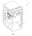
figure 1 représente une vue écorchée en perspective d'une machine à laver et à sécher le linge conforme à un mode de réalisation de l'invention.
- the
figure 1 represents a cut-away perspective view of a washing machine and drying clothes according to one embodiment of the invention.
On va décrire un mode de réalisation de l'invention en référence à la
On a représenté pour décrire l'invention une cuve de lavage 1 d'une machine à laver et sécher le linge conforme à l'invention, montée en communication sur un circuit de ventilation de séchage 2.There is shown to describe the invention a washing tub 1 of a washing machine and drying the laundry according to the invention, mounted in communication on a drying ventilation circuit 2.
On va décrire tout d'abord, les éléments communs à une machine à laver le linge et à une machine à laver et à sécher le linge selon un mode de réalisation de l'invention.The elements common to a washing machine and to a washing and drying machine according to one embodiment of the invention will be described first.
Bien entendu, l'ensemble est placé dans une carrosserie 3 de machine 4, qui n'a pas besoin d'être décrite ici.Of course, the assembly is placed in a
En outre, l'ensemble des autres moyens nécessaires au fonctionnement d'une machine lavante-séchante ou à laver seule, tels que, par exemple, les moyens de commande, d'alimentation électrique, ne sont pas représentés ou décrits dès lors qu'ils peuvent être identiques à ceux bien connus de l'homme du métier dans ce domaine.In addition, all the other means necessary for the operation of a washer-dryer or washing-only machine, such as, for example, the control means, power supply, are not shown or described as soon as they may be identical to those well known to those skilled in this field.
Cette machine à laver ou à laver et à sécher le linge 4 comprend tout d'abord une cuve de lavage 1, de forme sensiblement cylindrique. Cette cuve de lavage 1 comprend ainsi une paroi longitudinale 11 en forme de cylindre, appelée communément virole, et deux flancs d'extrémité 12 communément appelés flasques, permettant d'obturer sensiblement cette cuve de lavage 1.This washing machine or washing and drying machine 4 comprises firstly a washing tub 1, of substantially cylindrical shape. This washing tank 1 thus comprises a longitudinal wall 11 in the form of a cylinder, commonly referred to as a ferrule, and two end flanks 12 commonly referred to as flanges, making it possible to substantially close off this washing tank 1.
Bien entendu, cette cuve de lavage 1 n'a pas besoin d'être de forme strictement cylindrique. Elle peut en particulier comporter dans sa paroi longitudinale 11 des portions déportées formant ainsi des logements adaptés à contenir des organes de fonctionnement de la machine 4, tels que par exemple une résistance chauffante destinée à être immergée dans l'eau de la cuve de lavage 1.Of course, this washing tub 1 does not need to be strictly cylindrical. It may in particular comprise in its longitudinal wall 11 remote portions thus forming housings adapted to contain operating members of the machine 4, such as for example a heating resistor intended to be immersed in the water of the washing tub 1 .
Cette cuve de lavage 1 est montée dans une machine 4 de telle sorte que son axe longitudinal X s'étend sensiblement horizontalement.This washing tank 1 is mounted in a machine 4 so that its longitudinal axis X extends substantially horizontally.
Un tambour 5 destiné à recevoir le linge à laver et sécher est monté dans la cuve de lavage 1.A drum 5 for receiving the laundry to be washed and dried is mounted in the washing tub 1.
Ce tambour 5 est de forme cylindrique. Il comporte ainsi une virole et deux flancs d'extrémité.This drum 5 is cylindrical in shape. It thus comprises a ferrule and two end flanks.
Ce tambour 5 est monté dans la cuve de lavage 2 de telle sorte que son axe longitudinal correspond avec l'axe horizontal longitudinal X de la cuve de lavage 2.This drum 5 is mounted in the washing tub 2 so that its longitudinal axis corresponds with the longitudinal horizontal axis X of the washing tub 2.
De manière classique dans une telle machine à laver ou à laver et à sécher le linge 4, la virole du tambour 5 est perforée, généralement sur l'intégralité de sa surface, de telle sorte que l'eau utilisée lors des différentes phases du cycle de lavage de la machine 4 peut entrer et être évacuée du tambour 5.In a conventional manner in such a washing machine or washing and drying laundry 4, the drum shell 5 is perforated, generally over its entire surface, so that the water used during the various phases of the cycle washing machine 4 can enter and be evacuated from the drum 5.
Ce tambour 5 est également monté en rotation de manière connue dans la cuve de lavage 2 grâce à des paliers de rotation.This drum 5 is also rotated in known manner in the washing tub 2 by means of rotational bearings.
Un moteur permet d'entraîner en rotation une poulie montée sur un arbre de rotation du tambour.A motor rotates a pulley mounted on a rotating shaft of the drum.
Le linge destiné à être lavé est placé dans le tambour 5 qui comporte une virole perforée pour permettre la circulation de l'eau lors des différentes phases du cycle de lavage du linge.The laundry to be washed is placed in the drum 5 which has a perforated ferrule to allow the flow of water during the different phases of the laundry cycle.
On va décrire à présent, en référence à la
Parallèlement au circuit de lavage du linge, la machine à laver et à sécher le linge 1 comprend un circuit de ventilation de séchage. Ce circuit d'air de séchage comprend généralement une conduite 21 de circulation d'air en communication avec le tambour 5 dans lequel est placé le linge. Le tambour 5 constitue ainsi un des éléments de ce circuit de ventilation de séchage.In parallel with the laundry circuit, the washing and drying machine 1 comprises a drying ventilation circuit. This drying air circuit generally comprises an air circulation duct 21 in communication with the drum 5 in which the laundry is placed. The drum 5 thus constitutes one of the elements of this drying ventilation circuit.
Traditionnellement, un ventilateur 17 est monté dans ce circuit d'air de séchage pour assurer la circulation d'air, un élément chauffant 13 est placé dans ce circuit d'air en amont du tambour 5 afin de monter en température l'air introduit dans le tambour 5 et permettre ainsi l'évaporation de l'eau contenue dans le linge à sécher.Traditionally, a
Un condenseur à eau 6 est généralement situé en aval du tambour 5 pour permettre la condensation de la vapeur d'eau présente dans l'air humide sortant du tambour.A water condenser 6 is generally located downstream of the drum 5 to allow condensation of the water vapor present in the moist air leaving the drum.
Afin d'amener l'air de séchage dans le tambour 5, le circuit de ventilation de séchage comprend au moins un orifice d'introduction d'air de séchage débouchant au niveau d'un flanc du tambour 5.In order to bring the drying air into the drum 5, the drying ventilation circuit comprises at least one drying air introduction opening opening at a side of the drum 5.
Dans les machines à chargement par le dessus, l'orifice d'introduction d'air de séchage est situé sur un flanc latéral de la cuve de lavage 2 et du tambour 5 monté en rotation dans cette cuve 2.In top loading machines, the air introduction port of drying is located on a side flank of the washing tub 2 and the drum 5 rotatably mounted in this tank 2.
Dans les machines à chargement frontal (non représentée), l'orifice d'introduction d'air de séchage débouche au niveau d'un flanc du tambour, à proximité de l'ouverture d'introduction du linge.In front-loading machines (not shown), the drying air introduction port opens at a side of the drum, close to the laundry introduction opening.
Dans ces machines, l'air traverse le tambour 5 et sort par les trous ménagés dans la virole du tambour 5 pour être ensuite aspiré dans le circuit d'air de séchage grâce à un orifice de sortie ménagé dans la cuve de lavage 2 en communication avec le circuit de ventilation de séchage.In these machines, the air passes through the drum 5 and out through the holes formed in the shell of the drum 5 to then be sucked into the drying air circuit through an outlet orifice in the washing tub 2 in communication with the drying ventilation circuit.
On décrit ici une machine à chargement par le dessus, la virole du tambour 5 et la paroi longitudinale de la cuve de lavage 2 comportant une ouverture permettant l'introduction et le retrait du linge.An overhead loading machine, the drum shell 5 and the longitudinal wall of the washing tub 2 are described with an opening for the introduction and removal of laundry.
Une machine à laver et à sécher le linge 4 comporte également un circuit de ventilation de séchage 2. Ce circuit de ventilation de séchage 2 comporte une gaine 21 montée à l'extérieur de la cuve de lavage 1 et mise en communication avec l'intérieur de la cuve de lavage 1 et du tambour 5 au niveau des flancs de la cuve de lavage 1 et du tambour 5.A washing and drying machine 4 also comprises a drying ventilation circuit 2. This drying ventilation circuit 2 comprises a sheath 21 mounted outside the washing tub 1 and placed in communication with the inside. of the washing tub 1 and the drum 5 at the sides of the washing tub 1 and the drum 5.
Afin d'assurer la circulation de l'air de séchage dans cette gaine 21, un ventilateur 17 est monté dans la gaine 21 en un endroit approprié.In order to ensure the circulation of the drying air in this sheath 21, a
En outre, un moyen d'écoulement en eau 6 peut être une rampe de condensation placée dans la cuve de lavage 1. Cette rampe de condensation peut être, de manière connue, un condenseur à eau permettant la condensation de la vapeur d'eau présente dans l'air de séchage.In addition, a water flow means 6 may be a condensation ramp placed in the washing tub 1. This condensation ramp may be, in known manner, a water condenser for the condensation of the water vapor present in the drying air.
Enfin, des moyens de chauffage (non représentés) sont généralement placés dans la gaine 21 à proximité d'un orifice d'introduction d'air de séchage dans la cuve de lavage 1 afin d'élever en température l'air de séchage destiné à venir en contact avec le linge à sécher.Finally, heating means (not shown) are generally placed in the sheath 21 near a drying air introduction port in the washing tub 1 to raise the drying air temperature to come into contact with the laundry to be dried.
Ces différents moyens de traitement de l'air de séchage dans le circuit de ventilation de séchage 2, constitués d'un condenseur 6 et d'un élément chauffant 13, sont indiqués à titre non limitatif dans ce mode de réalisation.These various means for treating the drying air in the drying ventilation circuit 2, consisting of a condenser 6 and a heating element 13, are indicated in a nonlimiting manner in this embodiment.
Dans le mode réalisation de l'invention décrit ci-après, en référence à la
Une machine à laver et à sécher le linge 4 comprend une carrosserie 3 enfermant une cuve de lavage 1 remplie en liquide à partir d'une prise d'arrivée en eau du réseau, ladite cuve de lavage 1 logeant un tambour rotatif 5.A washing and drying machine 4 comprises a
Ladite machine 4 comprend une première vanne 7 d'alimentation en eau du réseau. La première vanne 7 d'alimentation en eau du réseau est reliée à une conduite 8 de circulation d'eau et un moyen de déviation 9 de la circulation d'eau.Said machine 4 comprises a first
Ledit moyen de déviation 9 de la circulation d'eau est relié :
- ○ d'une part à une première conduite 10 d'alimentation en eau débouchant sur un dispositif utilisant de l'eau ; et
- ○ d'autre part à un moyen d'écoulement d'eau 6 par l'intermédiaire d'une seconde conduite 14 d'alimentation en eau et une seconde vanne 15 d'alimentation en eau, ladite seconde vanne 15 d'alimentation en eau étant en série avec la première vanne 7 d'alimentation en eau du réseau de la machine 4.
- On the one hand to a first water supply pipe leading to a device using water; and
- On the other hand to a water flow means 6 via a second
water supply pipe 14 and a second water supply valve 15, said second water supply valve 15 being in series with thefirst valve 7 for supplying water to the network of the machine 4.
Ainsi, l'alimentation en eau du circuit hydraulique depuis une première vanne 7 d'alimentation en eau du réseau permet d'alimenter d'une part un dispositif utilisant de l'eau et d'autre part un moyen d'écoulement 6 de la machine à laver et à sécher le linge 4.Thus, the water supply of the hydraulic circuit from a first
De cette manière, une première vanne 7 d'alimentation en eau du réseau permet de distribuer l'eau du réseau à deux organes 6, 13 différents du circuit hydraulique de la machine 4. Les deux organes 6, 13 du circuit hydraulique ont des fonctions différentes dans la machine 4.In this way, a first
L'utilisation d'une seule vanne 7 d'alimentation en eau du réseau pour deux éléments 6, 13 du circuit hydraulique permet de réduire les coûts d'obtention d'une machine à laver et à sécher le linge et de minimiser l'encombrement nécessaire à l'alimentation en eau du réseau de la machine 4.The use of a single
La distribution de l'eau du réseau dans le circuit hydraulique provenant de la première vanne 7 d'alimentation en eau du réseau est réalisée par un moyen de déviation 9 de la circulation d'eau. Ce moyen de déviation 9 de la circulation d'eau permet de dévier tout ou partie de l'eau provenant de ladite première vanne 7 d'alimentation en eau du réseau.The distribution of the network water in the hydraulic circuit from the first
Avantageusement, le dispositif utilisant de l'eau relié à la conduite 10 d'alimentation en eau est au moins un élément chauffant 13 destiné à générer de la vapeur.Advantageously, the device using water connected to the water supply pipe 10 is at least one heating element 13 for generating steam.
Le moyen de déviation 9 de la circulation d'eau permet d'alimenter en eau l'élément chauffant 13 pour la génération de vapeur et un moyen d'écoulement 6 d'eau de la machine 4. Ce moyen d'écoulement 6 de la circulation d'eau est un élément simple et peu onéreux permettant de réduire le coût d'obtention de la machine à laver et à sécher le linge.The deflection means 9 of the water circulation makes it possible to supply water to the heating element 13 for the steam generation and a water flow means 6 for the machine 4. This flow means 6 of the Circulation of water is a simple and inexpensive element to reduce the cost of obtaining the washing machine and drying laundry.
Dans un autre mode de réalisation de l'invention, le dispositif utilisant de l'eau peut être une boîte pour des produits de lavage.In another embodiment of the invention, the device using water may be a box for detergents.
Cette boîte pour des produits de lavage peut notamment servir à déverser un produit imperméabilisant dans la cuve de lavage 1 au cours d'un cycle d'imperméabilisation des pièces de linge, ou encore de la javel au cours d'un cycle de lavage pour désinfecter des pièces de linge.This box for washing products can be used to pour a waterproofing product in the washing tub 1 during a waterproofing cycle of laundry items, or bleach during a wash cycle to disinfect laundry items.
Ladite boîte pour des produits de lavage est une boîte auxiliaire et pouvant se trouver en partie supérieure de la machine à laver le linge 4 de sorte que l'utilisateur puisse remplir ladite boîte aisément.Said box for washing products is an auxiliary box and can be located in the upper part of the washing machine 4 so that the user can fill said box easily.
Dans un autre mode de réalisation de l'invention, le dispositif utilisant de l'eau peut être une pompe de distribution d'un détergent pour une boîte déversant des produits de lavage dans la cuve de lavage 1.In another embodiment of the invention, the device using water may be a detergent dispensing pump for a can spilling detergents into the wash tub 1.
Le moyen de déviation de la circulation d'eau est un séparateur de flux d'eau en forme de Y.The water flow diverting means is a Y-shaped water flow separator.
Le moyen de déviation 9 de la circulation d'eau est positionné en amont de la conduite 10 d'alimentation en eau débouchant sur ledit au moins un élément chauffant 13 destiné à générer de la vapeur, ainsi que du moyen d'écoulement d'eau 6.The deflection means 9 of the water circulation is positioned upstream of the water supply pipe 10 opening on said at least one heating element 13 intended to generate steam, as well as the water flow means 6.
Une seconde vanne 15 d'alimentation en eau est reliée en série avec la première vanne 7 d'alimentation en eau du réseau.A second water supply valve 15 is connected in series with the first
L'alimentation en eau du moyen d'écoulement 6 d'eau est mise en oeuvre lorsque la première vanne 7 et la seconde vanne 15 sont ouvertes ensemble.The water supply of the water flow means 6 is implemented when the
Un clapet de surpression 16 est placé dans la conduite 10 d'alimentation en eau reliant le moyen de déviation 9 de la circulation d'eau au dispositif utilisant de l'eau.A pressure relief valve 16 is placed in the water supply line connecting the water circulation deflection means 9 to the water-using device.
Ainsi, le moyen d'écoulement 6 est alimenté avec la totalité de l'eau du réseau fournie par la première vanne 7 d'alimentation.Thus, the flow means 6 is fed with all of the mains water supplied by the
Dans un mode de réalisation de l'invention, le clapet de surpression 16 comprend une bille et un ressort calibré. Lorsque le clapet de surpression 16 est fermé, la bille est plaquée contre une paroi en forme de V pour empêcher le passage de l'eau. Le ressort calibré sert à maintenir le clapet de surpression 16 fermé. Et lorsque la pression exercée sur le clapet de surpression est supérieure à une valeur seuil alors la bille se décolle de la paroi en forme de V et l'eau passe au travers du clapet de surpression 16, le ressort calibré ayant une force inférieure à la pression exercée sur la bille.In one embodiment of the invention, the pressure relief valve 16 comprises a ball and a calibrated spring. When the overpressure valve 16 is closed, the ball is pressed against a V-shaped wall to prevent the passage of water. The calibrated spring serves to maintain the pressure relief valve 16 closed. And when the pressure exerted on the pressure relief valve is greater than a threshold value then the ball comes off the V-shaped wall and the water passes through the pressure relief valve 16, the calibrated spring having a lower force than the pressure exerted on the ball.
Le dispositif utilisant de l'eau est alimenté en eau lorsque la première vanne 7 d'alimentation en eau du réseau est ouverte et que la seconde vanne 15 d'alimentation en eau est fermée.The water-using device is supplied with water when the first
La pression de l'eau du réseau provenant de la première vanne 7 d'alimentation ouvre le clapet de surpression 16 de sorte à alimenter le dispositif utilisant de l'eau par la première conduite 10 d'alimentation en eau.The pressure of the mains water from the
Lorsque les première et seconde vannes 7, 15 d'alimentation sont ouvertes, la pression résiduelle en sortie du moyen de déviation 9 de la circulation d'eau est suffisante pour fermer le clapet à surpression 16 puisque le débit d'eau est régulé par la seconde vanne 15 d'alimentation en eau et non par le moyen d'écoulement 6.When the first and
Le moyen d'écoulement d'eau 6 comprend une ou plusieurs ouvertures d'évacuation d'eau placées en dessous de l'ouverture d'évacuation d'eau de la conduite 10 d'alimentation en eau débouchant sur le dispositif utilisant de l'eau.The water flow means 6 comprises one or more water discharge openings placed below the water discharge opening of the water supply pipe leading to the device using water. water.
Ainsi, la circulation d'eau est préférentiellement dirigée vers le moyen d'écoulement d'eau 6. De cette manière, la machine à laver et sécher le linge 4 peut comprendre ou non un clapet de surpression 16 pour distribuer l'eau entre le moyen d'écoulement 6 d'eau et la conduite 10 d'alimentation en eau débouchant sur le dispositif utilisant de l'eau.Thus, the flow of water is preferably directed towards the water flow means 6. In this way, the washing machine and drying the laundry 4 may or may not include a pressure relief valve 16 to distribute the water between the water flow means 6 and the water supply pipe 10 leading to the device using water.
Dans un autre mode de réalisation de l'invention, la seconde vanne d'alimentation 15 et le clapet à surpression 16 peuvent être inversés de sorte que ladite seconde vanne d'alimentation 15 est reliée à la conduite 10 d'alimentation en eau débouchant sur le dispositif utilisant de l'eau et que le clapet à surpression 16 est relié au moyen d'écoulement d'eau 6.In another embodiment of the invention, the second supply valve 15 and the overpressure valve 16 can be inverted so that said second supply valve 15 is connected to the water supply pipe 10 leading to the device using water and that the overpressure valve 16 is connected to the water flow means 6.
Dans ce mode de réalisation de l'invention, le clapet à surpression 16 est placé en partie basse par rapport à la seconde vanne d'alimentation 15. Par conséquent, la hauteur de colonne d'eau doit être inférieure à un seuil pour éviter une ouverture intempestive dudit clapet à surpression 16.In this embodiment of the invention, the overpressure valve 16 is placed in the lower part relative to the second supply valve 15. Therefore, the water column height must be less than a threshold to avoid a inadvertent opening of said overpressure valve 16.
Dans les essais réalisés par la Demanderesse, la hauteur de colonne d'eau est de l'ordre de 0,3 m, soit environ 0,03 bar.In the tests carried out by the Applicant, the height of the water column is of the order of 0.3 m, or about 0.03 bar.
Bien entendu, la valeur du seuil de hauteur de colonne d'eau pour ce mode de réalisation de l'invention n'est nullement limitative.Of course, the value of the water column height threshold for this embodiment of the invention is in no way limiting.
Dans un mode de réalisation où le clapet de surpression 16 est inopérant ou absent, la différence de hauteur entre le moyen d'écoulement 6 et la conduite 10 d'alimentation en eau du dispositif utilisant de l'eau doit être suffisante pour éviter que l'eau du réseau ne remonte pas jusqu'au dispositif utilisant de l'eau lorsque la seconde vanne 15 d'alimentation en eau est ouverte.In an embodiment where the pressure relief valve 16 is inoperative or absent, the difference in height between the flow means 6 and the water supply pipe 10 of the device using water must be sufficient to prevent the The mains water does not rise back to the device using water when the second water supply valve 15 is open.
La différence de hauteur entre la sortie du moyen d'écoulement 6 et la sortie, ou encore le point le plus haut, de la conduite 10 d'alimentation en eau du dispositif utilisant de l'eau est de l'ordre de 6 à 10cm suivant les essais réalisés par la Demanderesse.The difference in height between the outlet of the flow means 6 and the outlet, or even the highest point, of the water supply pipe 10 of the device using water is of the order of 6 to 10 cm. according to the tests carried out by the Applicant.
Bien entendu, cette plage de valeur de hauteur pour ce mode de réalisation de l'invention n'est nullement limitative, et ladite hauteur dépend notamment des pertes de charge du circuit hydraulique.Of course, this range of height value for this embodiment of the invention is in no way limiting, and said height depends in particular load losses of the hydraulic circuit.
Un moyen d'injection d'eau est placé à une extrémité de la conduite 10 d'alimentation en eau du dispositif utilisant de l'eau.A water injection means is placed at one end of the water supply line of the device using water.
Dans un mode de réalisation préféré de l'invention, le moyen d'injection d'eau est réalisé par une striction de la section de la conduite 10 d'alimentation en eau débouchant sur le dispositif utilisant de l'eau.In a preferred embodiment of the invention, the water injection means is made by a necking of the section of the water supply pipe 10 opening on the device using water.
Le moyen d'injection d'eau de la conduite 10 débouchant sur le dispositif utilisant de l'eau permet de favoriser une circulation d'eau directe sur le moyen d'écoulement d'eau 6. Par conséquent, la distribution d'eau dans le circuit hydraulique pourra être réalisée avec ou sans le clapet de surpression 16.The means for injecting water from the pipe 10 opening onto the device using water makes it possible to promote a direct flow of water on the water flow means 6. Therefore, the water distribution in the hydraulic circuit can be made with or without the pressure relief valve 16.
Le positionnement de la sortie d'évacuation d'eau du moyen d'écoulement 6 d'eau en dessous de la sortie d'évacuation de la conduite 10 d'alimentation en eau et l'utilisation d'un moyen d'injection d'eau placée à l'extrémité de sortie de la conduite 10 permet de garantir une arrivée d'eau satisfaisante au moyen d'écoulement 6 depuis la première vanne 7 d'alimentation en eau du réseau.Positioning the water discharge outlet of the water flow means 6 below the drain outlet of the water supply pipe 10 and the use of an injection means of water placed at the outlet end of the pipe 10 ensures a satisfactory water supply by means of flow 6 from the
La longueur de la conduite 10 d'alimentation en eau débouchant sur le dispositif utilisant de l'eau, pouvant être destiné à générer de la vapeur, est comprise entre 10cm et 50cm, et préférentiellement de l'ordre de 35cm.The length of the water supply pipe 10 leading to the device using water, which may be intended to generate steam, is between 10 cm and 50 cm, and preferably of the order of 35 cm.
Une longueur réduite de la conduite 10 permet d'éviter les problèmes de cheminement et d'encombrement entre la cuve de lavage 1 et la carrosserie 3.A reduced length of the pipe 10 makes it possible to avoid the problems of routing and space between the washing tank 1 and the
La longueur de la conduite 14 reliant le moyen de déviation 9 de la circulation d'eau au moyen d'écoulement d'eau 6 peut être inférieure à la longueur de la conduite 10 d'alimentation en eau débouchant sur le dispositif utilisant de l'eau.The length of the
De cette manière, la circulation d'eau en direction du moyen d'écoulement d'eau 6 est favorisée.In this way, the flow of water towards the water flow means 6 is promoted.
L'utilisation d'un clapet de surpression permet d'améliorer la distribution d'eau dans le circuit hydraulique de manière générale.The use of a pressure relief valve makes it possible to improve the distribution of water in the hydraulic circuit generally.
On va décrire à présent un mode de réalisation particulier appliqué à une machine à laver et à sécher le linge conforme à l'invention.We will now describe a particular embodiment applied to a washing machine and drying the laundry according to the invention.
La machine à laver et à sécher le linge 4 comprend au moins un élément chauffant 13 destiné à générer de la vapeur.The washing and drying machine 4 comprises at least one heating element 13 for generating steam.
Dans le cas d'une machine à laver et à sécher le linge, ledit au moins un élément chauffant 13 destiné à générer de la vapeur est placé dans une conduite de ventilation 21, ladite conduite 21 de ventilation étant reliée au tambour 5 pour introduire la vapeur dans ledit tambour 5 au travers d'orifices.In the case of a washing and drying machine, said at least one heating element 13 for generating steam is placed in a ventilation duct 21, said ventilation duct 21 being connected to the drum 5 to introduce the vapor in said drum 5 through orifices.
La génération de vapeur est réalisée en injectant de l'eau depuis la conduite d'alimentation 10 sur ledit au moins un élément chauffant 13 placé à l'intérieur de la conduite de ventilation 21 du circuit d'air de séchage 2. La vapeur générée par ledit au moins un élément chauffant 13 est transportée par le flux d'air circulant dans la conduite de ventilation 21. La vapeur est directement introduite dans le tambour 5.Steam generation is performed by injecting water from supply line 10 onto said at least one heating element 13 located within ventilation duct 21 of drying air circuit 2. Steam generated by said at least one heating element 13 is conveyed by the flow of air flowing in the ventilation duct 21. The steam is directly introduced into the drum 5.
L'injection de vapeur dans la conduite de ventilation 21 est effectuée par un moyen d'injection réalisé à une extrémité de sortie de la conduite 10 d'alimentation en eau.The injection of steam into the ventilation duct 21 is carried out by means injection at an outlet end of the water supply pipe.
La vapeur produite par ledit au moins un élément chauffant 13 et introduite dans le tambour 5 permet de défroisser le linge contenu dans ce dernier. Le défroissage par vapeur peut notamment être mis en oeuvre au cours d'un cycle de séchage du linge.The steam produced by said at least one heating element 13 and introduced into the drum 5 makes it possible to straighten the laundry contained in the latter. Steam stripping can in particular be implemented during a laundry drying cycle.
Le moyen d'écoulement 6 d'eau alimenté par la première vanne 7 d'alimentation en eau du réseau est une rampe de condensation de la vapeur évacuée du tambour 5 de ladite machine 4.The water flow means 6 supplied by the first
La rampe de condensation 6 est placée à l'intérieur de la cuve de lavage 1 pour condenser la vapeur produite lors d'un cycle de séchage du linge.The condensation ramp 6 is placed inside the washing tub 1 to condense the steam produced during a drying cycle of the laundry.
La première vanne 7 d'alimentation en eau du réseau est montée en parallèle avec au moins une vanne d'alimentation (non représentée) d'une boîte à produits lessiviels en eau du réseau.The first
La première vanne 7 d'alimentation en eau du réseau et ladite au moins une vanne d'alimentation d'une boîte à produits lessiviels en eau du réseau sont positionnés sur une paroi arrière de la machine à laver et à sécher le linge 4.The first
L'alimentation de la boîte à produits lessiviels peut nécessiter trois vannes d'alimentation en eau du réseau notamment lors d'utilisation de jets croisés pour délivrer les produits lessiviels dans la cuve de lavage 1.The supply of the detergent box may require three water supply network valves, especially when using cross-jet to deliver detergent products in the washing tub 1.
Les quatre vannes reliées au réseau d'eau dont les trois vannes d'alimentation de la boîte à produits lessiviels en eau du réseau et la première vanne 7 d'alimentation en eau du réseau pour la génération de vapeur et pour la rampe de condensation sont montées sur un support commun. Le support commun aux quatre vannes peut être réalisé en matière plastique. Ce support commun peut comprendre une arrivée commune de l'eau du réseau et une sortie d'eau du réseau associée à chacune des vannes pour que ladite première vanne alimente le dispositif de génération de vapeur ou la rampe de condensation et que les autres vannes alimentent la boîte pour des produits lessiviels. Chaque vanne a sa sortie d'eau reliée à une conduite d'alimentation en eau.The four valves connected to the water network including the three feed valves of the network water detergent box and the first
Ces quatre vannes sont positionnées suivant la forme d'un carré. Chacune des vannes se trouvant à un angle du carré.These four valves are positioned in the shape of a square. Each of the valves being at an angle of the square.
Ces quatre vannes sont des électrovannes alimentées en énergie électrique par l'intermédiaire de la machine 4, elle-même reliée au réseau électrique par un cordon électrique.These four valves are solenoid valves supplied with electrical energy via the machine 4, itself connected to the electrical network by an electrical cord.
L'utilisation d'une première vanne 7 d'alimentation en eau du réseau pour la génération de vapeur et pour la rampe de condensation permet de réduire les coûts d'obtention des machines à laver et à sécher le linge et de simplifier le circuit hydraulique. L'encombrement et le cheminement entre la cuve de lavage 1 et la carrosserie 3 des conduites d'alimentation en eau sont réduits.The use of a first network
Le débit d'eau de la première vanne 7 d'alimentation en eau du réseau est inférieur au débit d'eau de ladite au moins une vanne d'alimentation d'une boîte à produits lessiviels en eau du réseau.The water flow rate of the first
Le débit d'eau nécessaire au fonctionnement de la génération de vapeur et de la rampe de condensation est inférieur à celui du fonctionnement de la boîte à produits lessiviels.The flow rate of water required for the operation of the steam generation and the condensation ramp is lower than that of the operation of the detergent box.
Le débit d'eau de la première vanne 7 d'alimentation en eau du réseau s'étend dans une plage comprise entre 1 litre/minute à 5 litres/minute, et préférentiellement de l'ordre de 3 litres/minute.The water flow rate of the first
Tandis que le débit d'eau de ladite au moins une vanne d'alimentation d'une boîte à produits lessiviels en eau du réseau est de l'ordre de 8 litres/minute.While the water flow rate of said at least one supply valve of a detergent box in water network is of the order of 8 liters / minute.
Bien entendu, de nombreuses modifications peuvent être apportées aux exemples de réalisation décrits ci-dessus sans sortir du cadre de l'invention.Of course, many modifications can be made to the embodiments described above without departing from the scope of the invention.
En particulier, les différents exemples de réalisation ont été décrits en relation avec une machine à laver et à sécher le linge à chargement par le dessus.In particular, the various exemplary embodiments have been described in connection with a washing machine and drying laundry load from above.
Bien entendu, la présente invention pourrait être mise en oeuvre de manière similaire dans une machine à laver et à sécher le linge à chargement frontal, ou une machine à laver le linge.Of course, the present invention could be similarly implemented in a front-loading washing machine and dryer, or a washing machine.
En particulier, le dispositif utilisant de l'eau peut être soit un dispositif de génération de vapeur, soit une boîte pour des produits de lavage, soit une pompe de distribution de détergent pour une machine à laver le linge ou pour une machine à laver et à sécher le linge.In particular, the device using water may be either a steam generating device, a box for detergents, or a detergent dispensing pump for a washing machine or a washing machine and to dry the laundry.
Claims (11)
- A laundry washing or washing-and-drying machine (4) comprising a frame (3) enclosing a wash tub (1) filled with liquid from a tap water inlet, said wash tub (1) housing a tumbler (5), said machine (4) comprising a first tap water supply valve (7), characterized in that the first tap water supply valve (7) is connected to a water-circulation conduit (8) and a means for diverting (9) the water's circulation, said means for diverting (9) the water's circulation is connected:to a first water supply conduit (10) opening out onto a device using the water; andto a means for running water (6) by way of a second water supply conduit (14) and a second water supply valve (15), said second water supply valve (15) being serially connected with the first tap water supply valve (7) of the machine (4).
- A laundry washing or washing-and-drying machine (4) according to claim 1, characterized in that the device using water connected to the first water supply conduit (10) is at least one heating element (13) intended to generate steam.
- A laundry washing or washing-and-drying machine (4) according to claim 1 or 2, characterized in that an excess pressure valve (16) is placed within the first water supply conduit (10) connecting the means for diverting (9) the water's circulation to the device using the water.
- A laundry washing or washing-and-drying machine (4) according to one of the claims 1 to 3, characterized in that a water injection means is placed at one end of the first water supply conduit (10) of the device using the water.
- A laundry washing or washing-and-drying machine (4) according to claim 4, characterized in that the water injection means is constructed by necking down the cross-section of the first water supply conduit (10) opening out onto the device using the water.
- A laundry washing or washing-and-drying machine (4) according to one of the claims 1 to 5, characterized in that the means for running water (6) comprises one or more water discharge openings placed beneath the water discharge opening of the first water supply conduit (10) of the device using the water.
- A laundry washing or washing-and-drying machine (4) according to one of the claims 1 to 6, characterized in that the means for diverting (9) the water's circulation is a Y-shaped water flow separator.
- A laundry washing or washing-and-drying machine (4) according to one of the claims 1 to 7, characterized in that the first tap water supply valve (7) is mounted in parallel with at least one supply valve supplying a detergent product container with tap water.
- A laundry washing or washing-and-drying machine (4) according to one of the claims 2 to 8, characterized in that said at least one heating element (13) intended to generate steam is placed within a fan conduit (21), said fan conduit (21) being connected to the tumbler (5) to introduce steam into said tumbler (5) by means of orifices.
- A laundry washing or washing-and-drying machine (4) according to one of the claims 1 to 9, characterized in that the means of running (6) the water supplied by the first tap water supply valve (7) is a ramp condensing the steam discharged from the tumbler (5) of said machine (4).
- A laundry washing or washing-and-drying machine (4) according to one of the claims 9 or 10, characterized in that the water flow rate of the first tap water supply valve (7) ranges between 1 liter/minute and 5 liters/minute inclusive, and preferentially about 3 liters/minute.
Priority Applications (1)
| Application Number | Priority Date | Filing Date | Title |
|---|---|---|---|
| PL08167486T PL2053155T3 (en) | 2007-10-26 | 2008-10-24 | Laundry washing machine or washer-dryer comprising means for diverting the water flow |
Applications Claiming Priority (1)
| Application Number | Priority Date | Filing Date | Title |
|---|---|---|---|
| FR0707698A FR2922902B1 (en) | 2007-10-26 | 2007-10-26 | WASHING OR WASHING AND DRYING MACHINE COMPRISING A MEANS OF DEVIATION OF WATER CIRCULATION |
Publications (2)
| Publication Number | Publication Date |
|---|---|
| EP2053155A1 EP2053155A1 (en) | 2009-04-29 |
| EP2053155B1 true EP2053155B1 (en) | 2010-12-22 |
Family
ID=39580157
Family Applications (1)
| Application Number | Title | Priority Date | Filing Date |
|---|---|---|---|
| EP08167486A Active EP2053155B1 (en) | 2007-10-26 | 2008-10-24 | Laundry washing machine or washer-dryer comprising means for diverting the water flow |
Country Status (6)
| Country | Link |
|---|---|
| EP (1) | EP2053155B1 (en) |
| AT (1) | ATE492677T1 (en) |
| DE (1) | DE602008004051D1 (en) |
| ES (1) | ES2355863T3 (en) |
| FR (1) | FR2922902B1 (en) |
| PL (1) | PL2053155T3 (en) |
Families Citing this family (3)
| Publication number | Priority date | Publication date | Assignee | Title |
|---|---|---|---|---|
| DE102009047154A1 (en) * | 2009-11-25 | 2011-06-16 | BSH Bosch und Siemens Hausgeräte GmbH | Laundry treatment appliance with a steam generator and method for operating a laundry treatment appliance |
| RU2536030C2 (en) * | 2012-02-06 | 2014-12-20 | Эл Джи Электроникс Инк. | Laundry treatment machine |
| CN103422329B (en) * | 2013-07-29 | 2016-05-25 | 无锡小天鹅股份有限公司 | Washing machine |
Family Cites Families (4)
| Publication number | Priority date | Publication date | Assignee | Title |
|---|---|---|---|---|
| KR101022226B1 (en) * | 2004-01-06 | 2011-03-17 | 삼성전자주식회사 | Washing Machine And Control Method Thereof |
| KR20050112232A (en) * | 2004-05-25 | 2005-11-30 | 삼성전자주식회사 | A washer equipping a deodorization means and control method thereof |
| KR100698147B1 (en) * | 2005-02-25 | 2007-03-26 | 엘지전자 주식회사 | Control Method for Washing Machine |
| US20070084000A1 (en) * | 2005-10-13 | 2007-04-19 | Bernardino Flavio E | Stain removal process using combination of low and high speed spin |
-
2007
- 2007-10-26 FR FR0707698A patent/FR2922902B1/en not_active Expired - Fee Related
-
2008
- 2008-10-24 EP EP08167486A patent/EP2053155B1/en active Active
- 2008-10-24 AT AT08167486T patent/ATE492677T1/en not_active IP Right Cessation
- 2008-10-24 DE DE602008004051T patent/DE602008004051D1/en active Active
- 2008-10-24 ES ES08167486T patent/ES2355863T3/en active Active
- 2008-10-24 PL PL08167486T patent/PL2053155T3/en unknown
Also Published As
| Publication number | Publication date |
|---|---|
| EP2053155A1 (en) | 2009-04-29 |
| DE602008004051D1 (en) | 2011-02-03 |
| ES2355863T3 (en) | 2011-03-31 |
| PL2053155T3 (en) | 2011-05-31 |
| FR2922902B1 (en) | 2009-12-11 |
| ATE492677T1 (en) | 2011-01-15 |
| FR2922902A1 (en) | 2009-05-01 |
Similar Documents
| Publication | Publication Date | Title |
|---|---|---|
| FR2930956A1 (en) | LAUNDRY TREATMENT APPARATUS HAVING ROTARY NOZZLE VAPOR SUPPLY UNIT | |
| FR2987848A1 (en) | MULTIVOY VALVE AND WASHING MACHINE COMPRISING SUCH A MULTIVOY VALVE | |
| EP2053155B1 (en) | Laundry washing machine or washer-dryer comprising means for diverting the water flow | |
| FR2930952A1 (en) | LAUNDRY MACHINE HAVING A STEAM FEEDING DEVICE | |
| EP2312045B1 (en) | Washing machine including a hydraulic water-distribution circuit provided with a vent device connected to an area in fluid communication with a washing tank | |
| EP2325373B1 (en) | Washing machine comprising a washing or rinsing reservoir | |
| EP1870506B1 (en) | Method of smoothing out the clothes in a laundry drying machine | |
| FR2993162A1 (en) | WASHING MACHINE COMPRISING A WASHING AND / OR RINSING WATER TANK | |
| FR2993160A1 (en) | DISHWASHING MACHINE COMPRISING A TANK | |
| EP2684503B1 (en) | Method for controlling the operation of a washing machine and associated washing machine | |
| FR2935993A1 (en) | Cloth washing and/or drying machine e.g. household front loading washer, has reservoir connected to water supply pipe that is connected to water supply pump of water utilizing device | |
| EP2441373B1 (en) | Device for dispensing liquid products | |
| EP2594685B1 (en) | Washing machine including a tank of washing and/or rinsing water | |
| EP2787111B1 (en) | Washing machine including a steam generator and related method | |
| EP2594679B1 (en) | Washing machine including a tank of washing and/or rinsing water | |
| FR3011254A1 (en) | APPARATUS FOR DRYING LAUNDRY COMPRISING A DEVICE FOR CLEANING AT LEAST ONE COMPONENT FOR CLEANING USING A CLEANING LIQUID | |
| EP2594678B1 (en) | Washing machine including a tank of washing and/or rinsing water | |
| EP1870510A2 (en) | Laundry drying machine comprising a steam generator | |
| FR2914324A1 (en) | Vapor generator descaling method for domestic condensation laundry dryer, involves accumulating condensate water in intermediate tank, and descaling vapor generator by passing water into generator, where water is circulated by lift pump | |
| EP2594680B1 (en) | Washing and/or rinsing water tank for a washing machine and associated washing machine | |
| EP2522267B1 (en) | Method for cleaning crockery in a dishwashing machine | |
| EP2441876B1 (en) | Device for dispensing liquid products | |
| EP2650421B1 (en) | Method for controlling the operation of a washing machine and associated washing machine | |
| FR3003275A1 (en) | LAUNDRY DRYING APPARATUS COMPRISING A STEAM GENERATOR AND A STEAM DIFFUSION NOZZLE | |
| FR2993164A1 (en) | METHOD FOR OPERATING CONTROL OF A WASHING MACHINE AND WASHING MACHINE THEREFOR |
Legal Events
| Date | Code | Title | Description |
|---|---|---|---|
| PUAI | Public reference made under article 153(3) epc to a published international application that has entered the european phase |
Free format text: ORIGINAL CODE: 0009012 |
|
| AK | Designated contracting states |
Kind code of ref document: A1 Designated state(s): AT BE BG CH CY CZ DE DK EE ES FI FR GB GR HR HU IE IS IT LI LT LU LV MC MT NL NO PL PT RO SE SI SK TR |
|
| AX | Request for extension of the european patent |
Extension state: AL BA MK RS |
|
| 17P | Request for examination filed |
Effective date: 20091026 |
|
| AKX | Designation fees paid |
Designated state(s): AT BE BG CH CY CZ DE DK EE ES FI FR GB GR HR HU IE IS IT LI LT LU LV MC MT NL NO PL PT RO SE SI SK TR |
|
| GRAP | Despatch of communication of intention to grant a patent |
Free format text: ORIGINAL CODE: EPIDOSNIGR1 |
|
| GRAS | Grant fee paid |
Free format text: ORIGINAL CODE: EPIDOSNIGR3 |
|
| GRAA | (expected) grant |
Free format text: ORIGINAL CODE: 0009210 |
|
| AK | Designated contracting states |
Kind code of ref document: B1 Designated state(s): AT BE BG CH CY CZ DE DK EE ES FI FR GB GR HR HU IE IS IT LI LT LU LV MC MT NL NO PL PT RO SE SI SK TR |
|
| REG | Reference to a national code |
Ref country code: GB Ref legal event code: FG4D Free format text: NOT ENGLISH |
|
| REG | Reference to a national code |
Ref country code: CH Ref legal event code: EP |
|
| REG | Reference to a national code |
Ref country code: IE Ref legal event code: FG4D |
|
| REF | Corresponds to: |
Ref document number: 602008004051 Country of ref document: DE Date of ref document: 20110203 Kind code of ref document: P |
|
| REG | Reference to a national code |
Ref country code: DE Ref legal event code: R096 Ref document number: 602008004051 Country of ref document: DE Effective date: 20110203 |
|
| REG | Reference to a national code |
Ref country code: ES Ref legal event code: FG2A Ref document number: 2355863 Country of ref document: ES Kind code of ref document: T3 Effective date: 20110331 |
|
| REG | Reference to a national code |
Ref country code: NL Ref legal event code: VDEP Effective date: 20101222 |
|
| PG25 | Lapsed in a contracting state [announced via postgrant information from national office to epo] |
Ref country code: LT Free format text: LAPSE BECAUSE OF FAILURE TO SUBMIT A TRANSLATION OF THE DESCRIPTION OR TO PAY THE FEE WITHIN THE PRESCRIBED TIME-LIMIT Effective date: 20101222 |
|
| LTIE | Lt: invalidation of european patent or patent extension |
Effective date: 20101222 |
|
| PG25 | Lapsed in a contracting state [announced via postgrant information from national office to epo] |
Ref country code: HR Free format text: LAPSE BECAUSE OF FAILURE TO SUBMIT A TRANSLATION OF THE DESCRIPTION OR TO PAY THE FEE WITHIN THE PRESCRIBED TIME-LIMIT Effective date: 20101222 Ref country code: SI Free format text: LAPSE BECAUSE OF FAILURE TO SUBMIT A TRANSLATION OF THE DESCRIPTION OR TO PAY THE FEE WITHIN THE PRESCRIBED TIME-LIMIT Effective date: 20101222 Ref country code: SE Free format text: LAPSE BECAUSE OF FAILURE TO SUBMIT A TRANSLATION OF THE DESCRIPTION OR TO PAY THE FEE WITHIN THE PRESCRIBED TIME-LIMIT Effective date: 20101222 Ref country code: AT Free format text: LAPSE BECAUSE OF FAILURE TO SUBMIT A TRANSLATION OF THE DESCRIPTION OR TO PAY THE FEE WITHIN THE PRESCRIBED TIME-LIMIT Effective date: 20101222 Ref country code: CY Free format text: LAPSE BECAUSE OF FAILURE TO SUBMIT A TRANSLATION OF THE DESCRIPTION OR TO PAY THE FEE WITHIN THE PRESCRIBED TIME-LIMIT Effective date: 20101222 Ref country code: BG Free format text: LAPSE BECAUSE OF FAILURE TO SUBMIT A TRANSLATION OF THE DESCRIPTION OR TO PAY THE FEE WITHIN THE PRESCRIBED TIME-LIMIT Effective date: 20110322 Ref country code: LV Free format text: LAPSE BECAUSE OF FAILURE TO SUBMIT A TRANSLATION OF THE DESCRIPTION OR TO PAY THE FEE WITHIN THE PRESCRIBED TIME-LIMIT Effective date: 20101222 Ref country code: FI Free format text: LAPSE BECAUSE OF FAILURE TO SUBMIT A TRANSLATION OF THE DESCRIPTION OR TO PAY THE FEE WITHIN THE PRESCRIBED TIME-LIMIT Effective date: 20101222 |
|
| REG | Reference to a national code |
Ref country code: PL Ref legal event code: T3 |
|
| REG | Reference to a national code |
Ref country code: IE Ref legal event code: FD4D |
|
| PG25 | Lapsed in a contracting state [announced via postgrant information from national office to epo] |
Ref country code: EE Free format text: LAPSE BECAUSE OF FAILURE TO SUBMIT A TRANSLATION OF THE DESCRIPTION OR TO PAY THE FEE WITHIN THE PRESCRIBED TIME-LIMIT Effective date: 20101222 Ref country code: PT Free format text: LAPSE BECAUSE OF FAILURE TO SUBMIT A TRANSLATION OF THE DESCRIPTION OR TO PAY THE FEE WITHIN THE PRESCRIBED TIME-LIMIT Effective date: 20110422 Ref country code: CZ Free format text: LAPSE BECAUSE OF FAILURE TO SUBMIT A TRANSLATION OF THE DESCRIPTION OR TO PAY THE FEE WITHIN THE PRESCRIBED TIME-LIMIT Effective date: 20101222 Ref country code: IS Free format text: LAPSE BECAUSE OF FAILURE TO SUBMIT A TRANSLATION OF THE DESCRIPTION OR TO PAY THE FEE WITHIN THE PRESCRIBED TIME-LIMIT Effective date: 20110422 Ref country code: GR Free format text: LAPSE BECAUSE OF FAILURE TO SUBMIT A TRANSLATION OF THE DESCRIPTION OR TO PAY THE FEE WITHIN THE PRESCRIBED TIME-LIMIT Effective date: 20110323 Ref country code: NO Free format text: LAPSE BECAUSE OF FAILURE TO SUBMIT A TRANSLATION OF THE DESCRIPTION OR TO PAY THE FEE WITHIN THE PRESCRIBED TIME-LIMIT Effective date: 20110322 |
|
| PG25 | Lapsed in a contracting state [announced via postgrant information from national office to epo] |
Ref country code: SK Free format text: LAPSE BECAUSE OF FAILURE TO SUBMIT A TRANSLATION OF THE DESCRIPTION OR TO PAY THE FEE WITHIN THE PRESCRIBED TIME-LIMIT Effective date: 20101222 Ref country code: NL Free format text: LAPSE BECAUSE OF FAILURE TO SUBMIT A TRANSLATION OF THE DESCRIPTION OR TO PAY THE FEE WITHIN THE PRESCRIBED TIME-LIMIT Effective date: 20101222 Ref country code: RO Free format text: LAPSE BECAUSE OF FAILURE TO SUBMIT A TRANSLATION OF THE DESCRIPTION OR TO PAY THE FEE WITHIN THE PRESCRIBED TIME-LIMIT Effective date: 20101222 |
|
| PLBE | No opposition filed within time limit |
Free format text: ORIGINAL CODE: 0009261 |
|
| STAA | Information on the status of an ep patent application or granted ep patent |
Free format text: STATUS: NO OPPOSITION FILED WITHIN TIME LIMIT |
|
| PG25 | Lapsed in a contracting state [announced via postgrant information from national office to epo] |
Ref country code: DK Free format text: LAPSE BECAUSE OF FAILURE TO SUBMIT A TRANSLATION OF THE DESCRIPTION OR TO PAY THE FEE WITHIN THE PRESCRIBED TIME-LIMIT Effective date: 20101222 Ref country code: IE Free format text: LAPSE BECAUSE OF FAILURE TO SUBMIT A TRANSLATION OF THE DESCRIPTION OR TO PAY THE FEE WITHIN THE PRESCRIBED TIME-LIMIT Effective date: 20101222 |
|
| 26N | No opposition filed |
Effective date: 20110923 |
|
| REG | Reference to a national code |
Ref country code: DE Ref legal event code: R097 Ref document number: 602008004051 Country of ref document: DE Effective date: 20110923 |
|
| BERE | Be: lapsed |
Owner name: FAGORBRANDT SAS Effective date: 20111031 |
|
| PG25 | Lapsed in a contracting state [announced via postgrant information from national office to epo] |
Ref country code: MC Free format text: LAPSE BECAUSE OF NON-PAYMENT OF DUE FEES Effective date: 20111031 |
|
| PG25 | Lapsed in a contracting state [announced via postgrant information from national office to epo] |
Ref country code: BE Free format text: LAPSE BECAUSE OF NON-PAYMENT OF DUE FEES Effective date: 20111031 |
|
| PG25 | Lapsed in a contracting state [announced via postgrant information from national office to epo] |
Ref country code: MT Free format text: LAPSE BECAUSE OF FAILURE TO SUBMIT A TRANSLATION OF THE DESCRIPTION OR TO PAY THE FEE WITHIN THE PRESCRIBED TIME-LIMIT Effective date: 20101222 |
|
| PG25 | Lapsed in a contracting state [announced via postgrant information from national office to epo] |
Ref country code: LU Free format text: LAPSE BECAUSE OF NON-PAYMENT OF DUE FEES Effective date: 20111024 |
|
| REG | Reference to a national code |
Ref country code: CH Ref legal event code: PL |
|
| GBPC | Gb: european patent ceased through non-payment of renewal fee |
Effective date: 20121024 |
|
| REG | Reference to a national code |
Ref country code: FR Ref legal event code: CA Effective date: 20130605 |
|
| PG25 | Lapsed in a contracting state [announced via postgrant information from national office to epo] |
Ref country code: GB Free format text: LAPSE BECAUSE OF NON-PAYMENT OF DUE FEES Effective date: 20121024 Ref country code: LI Free format text: LAPSE BECAUSE OF NON-PAYMENT OF DUE FEES Effective date: 20121031 Ref country code: CH Free format text: LAPSE BECAUSE OF NON-PAYMENT OF DUE FEES Effective date: 20121031 |
|
| PG25 | Lapsed in a contracting state [announced via postgrant information from national office to epo] |
Ref country code: TR Free format text: LAPSE BECAUSE OF FAILURE TO SUBMIT A TRANSLATION OF THE DESCRIPTION OR TO PAY THE FEE WITHIN THE PRESCRIBED TIME-LIMIT Effective date: 20101222 |
|
| PG25 | Lapsed in a contracting state [announced via postgrant information from national office to epo] |
Ref country code: HU Free format text: LAPSE BECAUSE OF FAILURE TO SUBMIT A TRANSLATION OF THE DESCRIPTION OR TO PAY THE FEE WITHIN THE PRESCRIBED TIME-LIMIT Effective date: 20101222 |
|
| REG | Reference to a national code |
Ref country code: ES Ref legal event code: PC2A Owner name: GROUPE BRANDT Effective date: 20150716 |
|
| REG | Reference to a national code |
Ref country code: FR Ref legal event code: TP Owner name: GROUPE BRANDT, FR Effective date: 20150818 |
|
| REG | Reference to a national code |
Ref country code: FR Ref legal event code: PLFP Year of fee payment: 8 |
|
| REG | Reference to a national code |
Ref country code: DE Ref legal event code: R081 Ref document number: 602008004051 Country of ref document: DE Owner name: GROUPE BRANDT, FR Free format text: FORMER OWNER: FAGORBRANDT SAS, RUEIL-MALMAISON, FR |
|
| REG | Reference to a national code |
Ref country code: FR Ref legal event code: GC Effective date: 20151013 |
|
| PGFP | Annual fee paid to national office [announced via postgrant information from national office to epo] |
Ref country code: PL Payment date: 20150903 Year of fee payment: 8 |
|
| REG | Reference to a national code |
Ref country code: FR Ref legal event code: PLFP Year of fee payment: 9 |
|
| REG | Reference to a national code |
Ref country code: FR Ref legal event code: PLFP Year of fee payment: 10 |
|
| PG25 | Lapsed in a contracting state [announced via postgrant information from national office to epo] |
Ref country code: PL Free format text: LAPSE BECAUSE OF NON-PAYMENT OF DUE FEES Effective date: 20161024 |
|
| REG | Reference to a national code |
Ref country code: FR Ref legal event code: PLFP Year of fee payment: 11 |
|
| PGFP | Annual fee paid to national office [announced via postgrant information from national office to epo] |
Ref country code: IT Payment date: 20190911 Year of fee payment: 12 |
|
| PGFP | Annual fee paid to national office [announced via postgrant information from national office to epo] |
Ref country code: DE Payment date: 20191024 Year of fee payment: 12 |
|
| PGFP | Annual fee paid to national office [announced via postgrant information from national office to epo] |
Ref country code: ES Payment date: 20191106 Year of fee payment: 12 |
|
| REG | Reference to a national code |
Ref country code: DE Ref legal event code: R119 Ref document number: 602008004051 Country of ref document: DE |
|
| PG25 | Lapsed in a contracting state [announced via postgrant information from national office to epo] |
Ref country code: DE Free format text: LAPSE BECAUSE OF NON-PAYMENT OF DUE FEES Effective date: 20210501 |
|
| PG25 | Lapsed in a contracting state [announced via postgrant information from national office to epo] |
Ref country code: IT Free format text: LAPSE BECAUSE OF NON-PAYMENT OF DUE FEES Effective date: 20201024 |
|
| REG | Reference to a national code |
Ref country code: ES Ref legal event code: FD2A Effective date: 20220128 |
|
| PG25 | Lapsed in a contracting state [announced via postgrant information from national office to epo] |
Ref country code: ES Free format text: LAPSE BECAUSE OF NON-PAYMENT OF DUE FEES Effective date: 20201025 |
|
| PGFP | Annual fee paid to national office [announced via postgrant information from national office to epo] |
Ref country code: FR Payment date: 20231027 Year of fee payment: 16 |