EP2052984A1 - Méthode pour former un couvercle et un tel couvercle - Google Patents
Méthode pour former un couvercle et un tel couvercle Download PDFInfo
- Publication number
- EP2052984A1 EP2052984A1 EP07119332A EP07119332A EP2052984A1 EP 2052984 A1 EP2052984 A1 EP 2052984A1 EP 07119332 A EP07119332 A EP 07119332A EP 07119332 A EP07119332 A EP 07119332A EP 2052984 A1 EP2052984 A1 EP 2052984A1
- Authority
- EP
- European Patent Office
- Prior art keywords
- tab
- foil
- lid
- ring
- extending
- Prior art date
- Legal status (The legal status is an assumption and is not a legal conclusion. Google has not performed a legal analysis and makes no representation as to the accuracy of the status listed.)
- Granted
Links
Images


Classifications
-
- B—PERFORMING OPERATIONS; TRANSPORTING
- B65—CONVEYING; PACKING; STORING; HANDLING THIN OR FILAMENTARY MATERIAL
- B65D—CONTAINERS FOR STORAGE OR TRANSPORT OF ARTICLES OR MATERIALS, e.g. BAGS, BARRELS, BOTTLES, BOXES, CANS, CARTONS, CRATES, DRUMS, JARS, TANKS, HOPPERS, FORWARDING CONTAINERS; ACCESSORIES, CLOSURES, OR FITTINGS THEREFOR; PACKAGING ELEMENTS; PACKAGES
- B65D17/00—Rigid or semi-rigid containers specially constructed to be opened by cutting or piercing, or by tearing of frangible members or portions
- B65D17/50—Non-integral frangible members applied to, or inserted in, preformed openings, e.g. tearable strips or plastic plugs
- B65D17/501—Flexible tape or foil-like material
- B65D17/502—Flexible tape or foil-like material applied to the external part of the container wall only
-
- B—PERFORMING OPERATIONS; TRANSPORTING
- B65—CONVEYING; PACKING; STORING; HANDLING THIN OR FILAMENTARY MATERIAL
- B65D—CONTAINERS FOR STORAGE OR TRANSPORT OF ARTICLES OR MATERIALS, e.g. BAGS, BARRELS, BOTTLES, BOXES, CANS, CARTONS, CRATES, DRUMS, JARS, TANKS, HOPPERS, FORWARDING CONTAINERS; ACCESSORIES, CLOSURES, OR FITTINGS THEREFOR; PACKAGING ELEMENTS; PACKAGES
- B65D2517/00—Containers specially constructed to be opened by cutting, piercing or tearing of wall portions, e.g. preserving cans or tins
- B65D2517/50—Non-integral frangible members applied to, or inserted in, a preformed opening
- B65D2517/5002—Details of flexible tape or foil-like material
- B65D2517/5013—Details of flexible tape or foil-like material the tape covering almost the whole of the container end panel
-
- B—PERFORMING OPERATIONS; TRANSPORTING
- B65—CONVEYING; PACKING; STORING; HANDLING THIN OR FILAMENTARY MATERIAL
- B65D—CONTAINERS FOR STORAGE OR TRANSPORT OF ARTICLES OR MATERIALS, e.g. BAGS, BARRELS, BOTTLES, BOXES, CANS, CARTONS, CRATES, DRUMS, JARS, TANKS, HOPPERS, FORWARDING CONTAINERS; ACCESSORIES, CLOSURES, OR FITTINGS THEREFOR; PACKAGING ELEMENTS; PACKAGES
- B65D2517/00—Containers specially constructed to be opened by cutting, piercing or tearing of wall portions, e.g. preserving cans or tins
- B65D2517/50—Non-integral frangible members applied to, or inserted in, a preformed opening
- B65D2517/504—Details of preformed openings
- B65D2517/5043—Details of preformed openings provided with a flange
- B65D2517/5051—Up-turned flange, i.e. extending away from container
- B65D2517/5054—Up-turned flange, i.e. extending away from container rolled or folded back, e.g. to avoid sharp edges
-
- B—PERFORMING OPERATIONS; TRANSPORTING
- B65—CONVEYING; PACKING; STORING; HANDLING THIN OR FILAMENTARY MATERIAL
- B65D—CONTAINERS FOR STORAGE OR TRANSPORT OF ARTICLES OR MATERIALS, e.g. BAGS, BARRELS, BOTTLES, BOXES, CANS, CARTONS, CRATES, DRUMS, JARS, TANKS, HOPPERS, FORWARDING CONTAINERS; ACCESSORIES, CLOSURES, OR FITTINGS THEREFOR; PACKAGING ELEMENTS; PACKAGES
- B65D2517/00—Containers specially constructed to be opened by cutting, piercing or tearing of wall portions, e.g. preserving cans or tins
- B65D2517/50—Non-integral frangible members applied to, or inserted in, a preformed opening
- B65D2517/504—Details of preformed openings
- B65D2517/5056—Details of preformed openings the edge of the preformed opening having a covering element or coating, e.g. to prevent cutting or for sealing purposes
-
- B—PERFORMING OPERATIONS; TRANSPORTING
- B65—CONVEYING; PACKING; STORING; HANDLING THIN OR FILAMENTARY MATERIAL
- B65D—CONTAINERS FOR STORAGE OR TRANSPORT OF ARTICLES OR MATERIALS, e.g. BAGS, BARRELS, BOTTLES, BOXES, CANS, CARTONS, CRATES, DRUMS, JARS, TANKS, HOPPERS, FORWARDING CONTAINERS; ACCESSORIES, CLOSURES, OR FITTINGS THEREFOR; PACKAGING ELEMENTS; PACKAGES
- B65D2517/00—Containers specially constructed to be opened by cutting, piercing or tearing of wall portions, e.g. preserving cans or tins
- B65D2517/50—Non-integral frangible members applied to, or inserted in, a preformed opening
- B65D2517/5072—Details of hand grip, tear- or lift-tab
- B65D2517/5083—Details of hand grip, tear- or lift-tab with means facilitating initial lifting of tape, e.g. lift or pull-tabs
-
- Y—GENERAL TAGGING OF NEW TECHNOLOGICAL DEVELOPMENTS; GENERAL TAGGING OF CROSS-SECTIONAL TECHNOLOGIES SPANNING OVER SEVERAL SECTIONS OF THE IPC; TECHNICAL SUBJECTS COVERED BY FORMER USPC CROSS-REFERENCE ART COLLECTIONS [XRACs] AND DIGESTS
- Y10—TECHNICAL SUBJECTS COVERED BY FORMER USPC
- Y10T—TECHNICAL SUBJECTS COVERED BY FORMER US CLASSIFICATION
- Y10T29/00—Metal working
- Y10T29/49—Method of mechanical manufacture
Definitions
- the invention concerns a method for preparing and forming a lid.
- the lid is concerned as well.
- the lid comprises a lid ring (Deckelring) and a lid foil (membrane), which work together and are coupled together by a sealing portion which seals in ring-like fashion the membrane to a panel of the preferably metallic ring.
- the metallic ring is outside formed to have a seaming edge (seamable outer portion) which is provided and shaped to be seamed by a multiple seam to a body flange of a body wall to cover the body with the ring and the foil, in other words to cover the body with the lid.
- Lid rings of metallic nature and lid foils of metallic, plastic or a combinatorial nature are known in several sorts and shapes.
- the flat ring flange onto which the foil is sealed (where the lid foil is sealed) has several different orientations. It can be horizontally oriented, it can be tilted upwards, and it can also be tilted downwards. It can even change its shape during sterilization of a closed container, where inner pressure supplies force in axial direction to act on the foil, transferred to the sealing portion and to the panel (ring flange). Different orientations can therefore be present, as well as different orientations can be selected for the foil covering the inner opening, which it covers before, during and/or after a sterilization process, cf.
- WO-A 2007/088212 (Impress), WO-A 2005/005277 (Crown), and WO-A 2007/45385 (Alcan). All these variants operate with foils that have different shapes during a sterilization process.
- the sterilization process provides high pressure and high temperature to make the food inside the container stable for longer storage and transport, and during this sterilization of up to 130°C, a pressure has to be resisted by the lid.
- the lid After such sterilization process, the lid has a task to provide long-time self-life, until a user wishes to open this lid. At this very time instant, the opening forces have to be very low, as contrary to those forces the lid and the foil have to withstand during sterilization processes. Not all processes in sterilizing do have counter-pressure, as many processes operate with continuous retort systems. In this field, it is a task of the invention as technical problem to provide a lid that has superior properties.
- the problem to solve is to provide a tab, and the tab should be closely lying with the membrane (foil). During all the process(es) on/in the fillers production line, it should not rise up, but stay as close as possible with and along the foil, considering the length of the tab that is near the panel of the lid ring, where the foil is sealed. Still, the tab should provide a grip portion that can be gripped by an end user when wishing to open the lid, far beyond in time after the sterilization process. The grip portion can not be lying parallel and very close to the foil; it must rise up or bend away from the foil, as having this shape after sterilization and during transport and storage as well as shelf life. This appears to be a contradictory problem, even more emphasized when thin foils are more commonly used in the future, and the tab that is provided with a strip made from the same material as the foil, has no own rigidity to actively keep the position that it has been placed to.
- the lid ring extends radially outward with a curl. This provides a shape to seam the lid ring to a body flange. Radially inward, the lid ring has a panel that is a flange, adapted to receive a foil sealed to it.
- the foil closes the inner opening of the lid ring, which in most cases is circular, but can also have other shapes like oblong, rectangular and square.
- At least an upper tool acts positively on an intermediate portion of the tab (and the underlying foil portion) to squeeze or press them together and urging the inner tab portion upwards in an angle, and away from in parallel position with respect to the foil.
- the problem is solved by the lid of claim 15 as well.
- the lid ring extends radially outward with a curl. This provides a shape to seam the lid ring to a body flange. Radially inward, the lid ring has a panel that is a flange, adapted to receive a foil sealed to it.
- the foil closes the inner opening of the lid ring, which in most cases is circular, but can also have other shapes like oblong, rectangular and square.
- a squeezed or pressed portion of the tab has urged the inner portion of the tab upwards in an angle. But only the inner portion.
- the central foil is provided with a tab that is preferably an extension of its material and is preferably folded over to be as close as possible next to the foil extension.
- the tab provided thereby is strip-like and can have a narrowing end extending radially inward (claim 11).
- the outer end is next to the radially outer end of the sealing portion of the flat panel of the metal ring. This outer end can be a fold of about 360°, it can also be an attaching place, to fix a separate tab in a suitable way by sealing, gluing or riveting to the outer end of the central foil (claim 19).
- the radial inner end of the tab is lying over the inner opening, above the foil, closing this opening.
- Foil and tab are in a substantially parallel relation.
- the inner portion then rises axially upward (upon press or squeeze action), but is limited in length extension.
- the remainder of the tab is lying (or maintained) close to the sealing foil, no matter whether the lid ring has a panel that is extending slanted upwards, purely horizontal, or slanted downwards.
- the sealing foil will follow this primary direction of the panel of the lid ring, as will follow the tab the orientation of the foil.
- the shape of the central foil can have many geometries in two aspects. Its basic shape depends on the shape of the lid ring as explained in the below paragraph. Its vertical shape depends on the orientation of the flat ring panel, and whether this is directed horizontally, slanted upwards or slanted downwards. The central portion of the panel therefore is either flat, domed downwards or domed upwards. It can change its shape due to pressure exerted from the inside of the filled container during sterilization, changing the surface in its shape and taking with this change of shape the tab that is oriented parallel or along the surface of the foil.
- the shape of the lid ring is in this embodiment round, it can have oblong, square and elongated shape as well.
- An inner end of the flat ring panel of the lid ring can have many shapes, an open curl, a closed curl, a flattened end of dual material layer (folded in or folded out), and a non-treated cut end. Preferred are closed curls or free cut ends that are covered by the overlying central foil.
- the shape of this tab is prepared by a press or squeeze operation, in which an upper tool and a lower tool work together.
- the upper tool provides a press or a squeeze force onto the tab in an area that is intermediate between the radially outer area and the shorter radially inner area of the tab, to make the inner area of the tab rising upwards by pressure or compression and reactive forces thereof.
- the press or squeeze operation is provided prior to closing, in fact it is provided during manufacture of the lid.
- the lid can then be stacked and sold and transported separately, or the lid can be attached to a body flange, leaving a three-part can open towards the bottom end, for filling. Then lids together with container bodies will be supplied to the customer.
- the sterilization occurs at the filler's plant, and the lid manufacturing might either be concluded when the lid is finished, or might be concluded when the lid and an additional body portion are seamed together.
- the press or squeeze operation is operated between the inwardly extending tab, preferably as folded back tab, and the seamed foil. This is in an area that is radially inward from the inner end of the flat flange and radially outward of the inner end of the tab. This is the intermediate portion between the two end portions of the tab, allowing the larger extent of the tab to stay close to the foil. Instead, only a small portion at the radially inward end is rising upwards and away from the foil.
- the squeeze can be done in a line or strip portion (claim 7), preferably along the whole width of the tab. It can also be dot-shaped (claim 8).
- a strip will provide enough compression force to squeeze or press the tab in the intermediate portion together with the foil, and - as a reaction or result - force the inner end of the tab axially upwards to open a gap, to later allow a human finger to reach or grip below this upward forced end.
- the upward end is still low enough to not prohibit or harm any sterilization processes, where the lid might change its shape and axial position.
- This squeezing or pressing also ensures that very thin foils and tabs, preferably those that have very little aluminum in it, keep and stay in this position, where the two tools have provided them to stay.
- the angle is between 10° to 45° as a sort of mean value of the shape of an upwards extending inner end of the tab, with respect to horizontal plane (claims 15, 3).
- one of the tools approaches the other (claim 6), thus tools are moved relative to each other.
- the lid is not yet fastened by a seam to a body, it can be readily handled and can be easily placed between the two tools providing the squeeze or press operation.
- the upper tool has a cavity (claim 9), into which the enforced bending of the inner end of the tab will occur. This is a free shaping of the inner end of the tab, forced or enforced by pressure and compression as well as deformation in a portion further radially outward than the radially inward end of the tab.
- cup shape when the place of pressure introduction and squeezing operation is more or less dot-shaped and not line-shaped.
- the cup is having lateral ends that shape further up than the inner central tongue portion of the tab (claim 10).
- the tool operates as explained and is shaped to have a flat press surface, providing the press or squeeze force to deflect or make the inner end of the tab rising upwards.
- This flat press surface acts in the intermediate portion of the tab.
- a flat holding portion radially outward, which can either be passive or can further provide forces onto the tab portion that is radially outward of the intermediate portion to force it close to the foil.
- Radially inward of the intermediate portion that is acted on by the flat press surface there is the cavity that receives the upward bent (or "upward bending") inner end of the graspable tab.
- This upward end is designed to allow a human finger to grip below it and tear the tab upward and away to release the foil from the sealing portion, in other words to open the container and gain access to the content.
- the preferred shape of flat press surface of the upper tool is a strip-shape.
- a strip also is line-shaped (claim 7) but will have a larger radial extension. When a small width of the line is presented, the strip is reduced to a thin line, when a thin line extends in radial direction, it will become a more or less wide line or a strip. This strip is still narrow (or limited in its extension), but it can also have a dot-shape which does not reach both lateral ends of the tab.
- the strip/line can have several forms or shapes in vertical section, a soft protrusion shape, further extending to a U-shape (claim 7), to effect a deeper impact on the intermediate portion, but actually axially deforms both, the tab intermediate portion and the corresponding underlying portion of the foil. They both will gain a U-shape.
- Further vertical section shapes of this protrusion can have V-form that also affects the intermediate portion of the tab and the corresponding underlying portion of the foil. This is seen in a vertical section, but also in horizontal or in lateral direction there can be several modifications.
- the line can be straight or the line can be slightly curved or bent in horizontal direction, to enhance the upward folding or upward rising action of the inner racial end portion of the tab.
- the line itself is not necessarily a continuous line, but can also be a discontinuous, dotted or broken line, in both straight and/or curved/bent manner.
- the foil preferably has a size that is adapted to the ring and slightly larger than the inner opening.
- the thickness of the foil is below about a 100 ⁇ m, and can preferably be as thin as 50 ⁇ m to 60 ⁇ m, when thinner aluminum layer portion or no aluminum portions as layers are used.
- the foil then consists of at least one or two plastic layers, with no metallic intermediate layer. Presently available foils are still thicker and have at least two or three layers.
- the inner layer can according to the invention have a thickness between 60 ⁇ m to 80 ⁇ m, preferably an aluminum layer covered on both sides by plastic layers that are thinner than the aluminum layer, but give protection and allow sealing.
- the foil can extend into the tab with the same material and layer characteristics in the tab as is throughout the central foil.
- the tab can have a material of different properties, it can be thicker, thinner and of other layer structure or of other material components along its structure or layers. This tab will then have to be fastened to the outer end, which can be done by gluing, by sealing and by providing the riveted or corrugated connection portion.
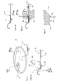
- FIG. 1 as perspective view shows some of the elements used in the embodiments of the invention.
- the tab 10 is provided as an elongated portion, close to the covering foil 3.
- the lid ring 2 preferably made from metal, but could as well be stiff plastic, has an outer curl 2a that is shown in section in sketch 2a ( figure 2a ) . This curl is suitable to be seamed to a body flange not shown here, but common in the technical field.
- the tab 10 reaches out to the outer, preferably circumferential edge of the foil, where it has a fold portion 10d, folding it back inwards and keeping it close to the profile of the membrane 3 as covering foil.
- An inner end portion 10b is tilted, as more detailed shown in the next figures, to rise up from the surface extension of the foil 3, allowing a finger grip to pick it up and tear along the tab 10. This shear force will open the sealing ring layer 9 that is provided as shown in figure 5 .
- Ring zone 9 as sealing provides a liquid tight seal of the foil 3 in its outer end ring 3b with respect to the lid ring 2 and its flange or flat ring panel 2b.
- the shape of the lid ring is in this embodiment round, it can have oblong, square and elongated shape as well.
- An inner end 2c of the flat ring panel of the lid ring can have many shapes, an open curl, a closed curl, a flattened end of dual material layer (folded in or folded out), and a non-treated cut end. Preferred are closed curls or free cut ends that are covered by the overlying central foil.
- the shape of the central foil can also have many geometries in two aspects. Its basic shape depends on the shape of the lid ring 2 as explained in the previous paragraph. Its vertical shape depends on the orientation of the flat ring panel 2b, and whether this is directed horizontally, slanted upwards or slanted downwards.
- the central portion 3c of the panel 3 therefore is either flat, domed downwards or domed upwards. It can change its shape due to pressure exerted from the inside of the filled container during sterilization, changing the surface 3" in its shape and taking with this change of shape the tab 10 that is oriented parallel or along the surface 3" of the foil.
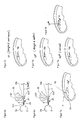
- the tab 10 is to be introduced in more detail. It has a flat (or fully parallel) initial position as shown in figure 2a , and it has a position after operating the upper and lower tools 30, 40 as shown in figures 3, 4 .
- the extension of the foil 3 with its surface 3" is to cover the opening 8 of the lid ring 2.
- the foil 3 has a central portion 3c and an outer portion that overlies the flat ring panel 2b and its inner curl 2c. Only a part of this portion is sealed with a sealing zone 9 to the flat ring panel 2b.
- the larger length portion y 10 extends radially inwards therefrom, and until that place of the tab 10, where it starts having an inner end portion angled upwards in an angle of between 10° to 45°, in of figure 5 shown slanted to about 45° as angle ⁇ .
- This angled upwards portion is rising axially upwards during a pressing or squeezing operation as explained with respect to figures 3 and 4 , has a length extension y 20 , which is less than one third of the sum of all length definitions y 30 to y 10 .
- the foil 30 therefore has an inner portion 3c and an outer portion 3b.
- the inner portion 3c is circular and the outer portion 3b is ring-shaped.
- the material of the tab 10 is the same as that one of the central foil 3, as explained in more detail in figures 5a and 5b , not explicitly shown in figure 5 .
- the tab has a fold portion 10d, emerging from the outer portion 3b of the foil, and folding back inwards to extend with the angled upwards inner end 10b, substantially away from the inner end 2c of the flat ring panel 2b.
- the outer radial portion 10a of the tab extends from the fold portion 10d radially inwards towards the intermediate portion 10c, which is at the radial inner end of the extension y 10 .
- a finger can grip in position G below the inner end portion 10b.
- the length of this portion is y 20 and allows a normal finger to reach both surfaces of the inner end 10b, to allow gripping this and tearing along the tab 10, opening the sealing zone 9 and the lid by a customer.
- This opening operation is sometime after the end of the sterilization, and until this time, the tab stays closely related, and having the inner end 10a rising upwards for use by the customer.
- the uprising end 10b is not detrimental to the process of sterilization.
- the lid foil 3 might change its shape and might be displaced cup-shaped upwards, and a very long freestanding end of a tab 10 would obstruct the sterilization process, especially in continuous retort systems.
- the lid as shown in figure 5 is placed between the upper tool 30 and the lower tool 40.
- the upper tool has a protrusion 32 which is extending downwards and may be line-shaped or dot-shaped.
- this protrusion Radially outward of this protrusion for providing the press or squeezing force in operation, is a flat holding portion, and radially inwards is a cavity 31, which receives the folded upwards inner end portion 10b of the tab, when the protrusion 32 acts on a part of the intermediate portion 10c, displaces material and lifts up the inner end portion 10b by displacement of material and pressing or squeezing a certain amount of foil material of the tab, providing the intimate contact 3' with the upper surface 3" of the foil 3 in the place of the protrusion 32.
- the protrusion 32 which acts to provide the pressing force F ax can have a shallow protrusion which is line-shaped laterally, across the tab extension, and has radially outward and radially inward the two portions 33, 31, as explained before.
- the upper tool of figure 4 is again shown in figures 6a, 6b , as it acts on the intermediate portion 10c of the tab 10.
- the tool of figure 6a has a V-shaped protrusion 32'.
- the tool of figure 6b has a U-shaped protrusion 32".
- Both tools 30 have the radially inward and upward extending cavity as the inner tool end, to allow the axially upward movement of the tab inner end 10b.
- the shape of the tool is different from the relatively smooth protrusion shape 32 of figure 4 .
- the shape of V and U are more exposed, to also act deforming on the foil 3 below the intermediate portion 10c of the tab.
- the intermediate portion 10c' will receive a V-shaped groove, as the corresponding underlying portion of foil 3 will receive the same shape.
- the U-deformed shape of figure 6b will also affect both, the tab 10 and the underlying portion of the foil 3, where the arrow 10c" points to.
- the lower tool 40 has a corresponding inverse shape, not separately displayed in figures 6a, 6b .
- All those explained tools can have in lateral direction shapes that are exemplified in figures 7c, 7d and 7e .
- the tab inner end portion 10b is slanted upwards, and this is effected by the protrusion 32, 32' or 32" making a press and squeeze line, either as a straight line 10f, as dotted or broken line 10f" or as laterally curved or bent line 10f".
- the tool can have broader or smaller width of this line having the different shapes 10f as explained, and the line will then be a strip portion which is wider than the line as such, but still be narrow in radial extension.
- Figure 7b shows a dot shape of the press and squeeze operation, effecting a shape of the tab inner end portion 10b to be schi-shaped or with other words, having a cup shape, where the lateral portions are bent upwards, and the inner end is also bent upwards and slimming in width.
- the dot can be smaller or wider in its radial extension and is effected by an upper tool, similar to that shown in figures 3 , 6a and 6b .
- the outer end 10d of the tab which is shown in all embodiments to be folded over.
- This fold can be replaced by an attaching portion, when the tab 10 is a separate device, but is initially fixed to the outer end portion of the central foil 3, and has a flat extension as shown in figure 2b in the first step.
- the fold 10b is then not present, but will be replaced by an attaching place, either glued, sealed, provided by a rivet or any other suitable corrugation which allows to transport force when pulling the tab 10 for opening the sealing strip 9 below the ring portion 3b of the foil 3.
- the lid itself is held in a fixed position between upper and lower tools 30, 40 and either the upper or the lower, or both tools are axially displaced forward towards the foil 3, to minimize the gap and to effect a pressing force. This is for all shapes of protrusions 32 and all explained tools 30, 40.
- the holding portion 33 of the upper tool 30 can support the orientation of the outer portion 10a, to be kept in parallel and close to the foil, prior to the start of the inner curl 2c.
- Both tools are radially inside of this inner curl end 2c, and do not effect forces or pressing action onto surfaces of the tab 10, radially outward the central portion 3c of the foil 3.
- the shape of the angled-upward inner end portion 10b will be substantially cup-shaped, having lateral end edges, which bulge upwards, as material is displaced in more directions.
- the material displacement is purely radial.
- the material With dot- or enlarged dot shaped protrusions, the material will be displaced circularly 10f"", from the respective contact point or contact zone of a circular protrusion with tab material in the intermediate portion 10c.
- Opening both tools 30, 40 allows withdrawal of the prepared lid, which was then formed and shaped, prepared for use in retort systems.
- the lid is also provided to be used by (end) customers after having been subject to sterilization processes, and this end user (customer) may still use the upwardly angled inner end portion 10b.
- the protrusion 32 can be called a narrow strip or small dot-shaped extension.
- the achieved upward angle is between 10° to 45°, the specific embodiment showing more than 40°, and a very short inner end portion 10b, which is between one fifth and one sixth of the overall length y 30 + y 10 + y 20 of the tab 10. The angle is most preferred between 20° to 30°.
- the upper tool 30, a hammer or coining tool that was explained in its operation does not reach radially outward over the ring-shaped portion r 3b .
- the outer portion thereof, which extension is termed y 30 can have some space between the tab extension close to the fold 10b and the sealed outer ring 3b of foil 3 which is still considered to be substantially parallel and close to the upper surface of the central foil.
- the main extension y 30 plus y 10 of the tab length is close and substantially parallel to the foil 3, no matter whether this is horizontally shaped, bulging upwards or downwardly cup-shaped, with a depending flange ring 2b of the lid ring 2.
- the inner end portion 10b is narrowing towards its inner end, separately shown in figure 7a . Widening towards the radially outward direction, the protrusion 32 may cover the whole width of the tab 10, when a strip portion is used as a press or squeeze initiator.
- Figure 5a has a foil which has a thickness d 7 of substantially 100 ⁇ m.
- the central layer 71 is preferably of aluminum and has a thickness d 71 , which is between 60 ⁇ m and 80 ⁇ m.
- the upper and lower covering layers have thicknesses of d 70 each, and provided as upper layer 70' and lower layer 70". Each of these layers has between 10 ⁇ m and 20 ⁇ m. They cover the aluminum layer 71, and the whole layer structure which has at least these three layers is used as central foil 3 and can also be used as extension over the fold portion 10d as tab 10.
- FIG. 5b An alternative foil 3 with less thickness is shown in figure 5b .
- Three layers are provided, each one being substantially of the same thickness, a central aluminum layer d 81 , covering layers d 80 on top and below, each one having about 20 ⁇ m thickness.
- d 8 provides a thickness of the whole foil as multilayer foil 3, which is substantially one half of the thickness of the foil 3 of figure 5a . Still, the aluminum layer as example of a metal layer can also be removed to have two plastic covering layers of thicknesses d 80 , to even further thin the foil 3 for use as covering foil and preferably as tab provision 10.
- the thinner (less) the thickness of the foil 3 is, the more important is the pressing fixation in the intermediate zone 10c for positioning the tab.
- the tab therefore can avoid that during the different operation after closing the container with the lid, is folded out.
- the tab does not fold out after different operations in time after the closing action, and receives its final position at the end of the forming process of the lid, as described.
Landscapes
- Engineering & Computer Science (AREA)
- Mechanical Engineering (AREA)
- Closures For Containers (AREA)
- Closing Of Containers (AREA)
- Packages (AREA)
- Laminated Bodies (AREA)
- Containers Opened By Tearing Frangible Portions (AREA)
- Lining Or Joining Of Plastics Or The Like (AREA)
- Rigid Containers With Two Or More Constituent Elements (AREA)
Priority Applications (19)
| Application Number | Priority Date | Filing Date | Title |
|---|---|---|---|
| DK07119332.0T DK2052984T3 (da) | 2007-10-25 | 2007-10-25 | Fremgangsmåde til forberedelse og dannelse af et låg og låg |
| AT07119332T ATE491645T1 (de) | 2007-10-25 | 2007-10-25 | Verfahren zum ausbilden eines deckels und deckel |
| PL07119332T PL2052984T3 (pl) | 2007-10-25 | 2007-10-25 | Sposób przygotowywania i formowania wieczka oraz wieczko |
| DE602007011290T DE602007011290D1 (de) | 2007-10-25 | 2007-10-25 | Verfahren zum Ausbilden eines Deckels und Deckel |
| PT07119332T PT2052984E (pt) | 2007-10-25 | 2007-10-25 | Método para preparar e formar uma tampa e tampa |
| EP07119332A EP2052984B1 (fr) | 2007-10-25 | 2007-10-25 | Méthode pour préparer et former un couvercle et couvercle |
| ES07119332T ES2357561T3 (es) | 2007-10-25 | 2007-10-25 | Procedimiento para preparar y formar una tapa, y tapa. |
| BRPI0818819 BRPI0818819A2 (pt) | 2007-10-25 | 2008-10-27 | Método para formar uma tampa e tal própria tampa rebitável |
| CA2701701A CA2701701A1 (fr) | 2007-10-25 | 2008-10-27 | Procede pour former un couvercle et ce couvercle pouvant etre serti |
| JP2010530482A JP2011500471A (ja) | 2007-10-25 | 2008-10-27 | 蓋を形成する方法及びこのような蓋自体が継合可能な蓋 |
| PCT/EP2008/064553 WO2009053495A1 (fr) | 2007-10-25 | 2008-10-27 | Procédé pour former un couvercle et ce couvercle pouvant être serti |
| KR1020107008976A KR20100072291A (ko) | 2007-10-25 | 2008-10-27 | 뚜껑 성형 방법 및 그 접합가능한 뚜껑 |
| MX2010003573A MX2010003573A (es) | 2007-10-25 | 2008-10-27 | Metodo para formar un reborde y el reborde suturable. |
| CN200880112863A CN101873971A (zh) | 2007-10-25 | 2008-10-27 | 用于形成盖子的方法以及这种可接合的盖子本身 |
| AU2008316445A AU2008316445A1 (en) | 2007-10-25 | 2008-10-27 | Method for forming a lid and such seamable lid itself |
| US12/739,051 US20100301045A1 (en) | 2007-10-25 | 2008-10-27 | Method for forming a lid and such seamable lid itself |
| RU2010120811/12A RU2010120811A (ru) | 2007-10-25 | 2008-10-27 | Способ образования крышки и завальцовываемая крышка |
| ZA2010/02273A ZA201002273B (en) | 2007-10-25 | 2010-03-30 | "method for forming a lid and such seamable lid itself" |
| MA32868A MA31893B1 (fr) | 2007-10-25 | 2010-05-25 | Procédé pour former un couvercle et ce couvercle pouvant être serti |
Applications Claiming Priority (1)
| Application Number | Priority Date | Filing Date | Title |
|---|---|---|---|
| EP07119332A EP2052984B1 (fr) | 2007-10-25 | 2007-10-25 | Méthode pour préparer et former un couvercle et couvercle |
Publications (2)
| Publication Number | Publication Date |
|---|---|
| EP2052984A1 true EP2052984A1 (fr) | 2009-04-29 |
| EP2052984B1 EP2052984B1 (fr) | 2010-12-15 |
Family
ID=39059334
Family Applications (1)
| Application Number | Title | Priority Date | Filing Date |
|---|---|---|---|
| EP07119332A Not-in-force EP2052984B1 (fr) | 2007-10-25 | 2007-10-25 | Méthode pour préparer et former un couvercle et couvercle |
Country Status (19)
| Country | Link |
|---|---|
| US (1) | US20100301045A1 (fr) |
| EP (1) | EP2052984B1 (fr) |
| JP (1) | JP2011500471A (fr) |
| KR (1) | KR20100072291A (fr) |
| CN (1) | CN101873971A (fr) |
| AT (1) | ATE491645T1 (fr) |
| AU (1) | AU2008316445A1 (fr) |
| BR (1) | BRPI0818819A2 (fr) |
| CA (1) | CA2701701A1 (fr) |
| DE (1) | DE602007011290D1 (fr) |
| DK (1) | DK2052984T3 (fr) |
| ES (1) | ES2357561T3 (fr) |
| MA (1) | MA31893B1 (fr) |
| MX (1) | MX2010003573A (fr) |
| PL (1) | PL2052984T3 (fr) |
| PT (1) | PT2052984E (fr) |
| RU (1) | RU2010120811A (fr) |
| WO (1) | WO2009053495A1 (fr) |
| ZA (1) | ZA201002273B (fr) |
Cited By (4)
| Publication number | Priority date | Publication date | Assignee | Title |
|---|---|---|---|---|
| WO2012072383A1 (fr) * | 2010-11-29 | 2012-06-07 | Crown Packaging Technology, Inc. | Fermeture |
| CN102574608A (zh) * | 2010-03-18 | 2012-07-11 | 印普瑞思集团有限公司 | 用于易打开容器的闭合件和设有该闭合件的容器 |
| CN104010944A (zh) * | 2011-12-20 | 2014-08-27 | 阿尔达制罐集团荷兰有限公司 | 用于容纳粉末材料并具有内部过压力的带可剥离密封膜的容器 |
| US9611082B2 (en) | 2013-05-13 | 2017-04-04 | Owens-Brockway Glass Container Inc. | Seal ring for foil-sealing a container |
Families Citing this family (7)
| Publication number | Priority date | Publication date | Assignee | Title |
|---|---|---|---|---|
| EP2341005B1 (fr) * | 2009-12-31 | 2012-10-31 | Ardagh MP Group Netherlands B.V. | Feuille pour fermer l'ouverture d'un récipient, pièce de récipient et récipient, et procédé et appareil de fabrication associés |
| GB201214716D0 (en) * | 2012-08-17 | 2012-10-03 | Crown Packaging Technology Inc | Metal cans with peelable lids |
| EP3279105A1 (fr) * | 2016-08-02 | 2018-02-07 | Amcor Flexibles Singen GmbH | Bague de couvercle |
| CN107253560A (zh) * | 2017-04-28 | 2017-10-17 | 浙江青莲食品股份有限公司 | 食品罐盖体及食品罐 |
| FR3072660B1 (fr) * | 2017-10-20 | 2019-11-22 | Ardagh Mp Group Netherlands B.V. | Couvercle pour boite de conserve metallique, comprenant un anneau metallique et membrane pelable thermoscellee |
| CN109941564A (zh) * | 2018-08-27 | 2019-06-28 | 济托赛文公司 | 粉末容器的密封盖 |
| KR101956857B1 (ko) * | 2018-08-27 | 2019-03-13 | (주)제로투세븐 | 분말용기의 밀봉캡 및 그 제조방법 |
Citations (8)
| Publication number | Priority date | Publication date | Assignee | Title |
|---|---|---|---|---|
| EP0090957A2 (fr) * | 1982-04-05 | 1983-10-12 | Sandherr Packungen AG | Couvercle pour boîtes stérilisables |
| US5020955A (en) * | 1987-12-14 | 1991-06-04 | Alcan Rorschach Ag | Method of manufacturing a closure unit made of sheet metal or plating and container having a closure unit obtained thereby |
| WO1999035045A1 (fr) * | 1998-01-07 | 1999-07-15 | Dispensing Containers Corp | Fermeture et recipient refermable a ouverture facile |
| EP1419972A2 (fr) | 2002-11-12 | 2004-05-19 | Sonoco Development, Inc. | Fermeture à ouverture facile pour un conteneur stérilisable |
| WO2005005277A1 (fr) | 2003-07-01 | 2005-01-20 | Crown Packaging Technology Inc | Fermeture |
| WO2006029991A1 (fr) | 2004-09-13 | 2006-03-23 | Crown Packaging Technology, Inc | Dispositif de pliage et de fixation de languette, et procede |
| WO2007045385A1 (fr) | 2005-10-20 | 2007-04-26 | Alcan Technology & Management Ltd. | Procede de fabrication d'un couvercle de boite presentant une bague de couvercle et une membrane de fermeture |
| WO2007088212A1 (fr) | 2006-02-03 | 2007-08-09 | Impress Metal Packaging S.A. | récipient extensible ayant un couvercle pour obtenir une régulation de chambre de pression d'une boite ALIMENTAIRE |
Family Cites Families (7)
| Publication number | Priority date | Publication date | Assignee | Title |
|---|---|---|---|---|
| CH629983A5 (de) * | 1978-06-06 | 1982-05-28 | Alusuisse | Verfahren zur herstellung von deckelringen fuer konservendosen. |
| CH668754A5 (de) * | 1985-07-10 | 1989-01-31 | Grabher Indosa Maschbau Ag | Verfahren zum verschliessen eines dosenartigen behaelters mittels einer membran. |
| GB8523263D0 (en) * | 1985-09-20 | 1985-10-23 | Metal Box Plc | Making metal can ends |
| GB9510515D0 (en) * | 1995-05-24 | 1995-07-19 | Metal Box Plc | Containers |
| DE29609130U1 (de) * | 1996-05-21 | 1997-09-18 | Rasselstein Hoesch GmbH, 56564 Neuwied | Leicht zu öffnender Dosendeckel |
| US6106757A (en) * | 1997-01-31 | 2000-08-22 | Tetra Laval Holdings & Finance S.A. | Beverage can lid and method of making |
| MY138331A (en) * | 2004-12-09 | 2009-05-29 | Crown Packaging Technology Inc | Method of and apparatus for forming a closure |
-
2007
- 2007-10-25 PT PT07119332T patent/PT2052984E/pt unknown
- 2007-10-25 DK DK07119332.0T patent/DK2052984T3/da active
- 2007-10-25 AT AT07119332T patent/ATE491645T1/de active
- 2007-10-25 DE DE602007011290T patent/DE602007011290D1/de active Active
- 2007-10-25 PL PL07119332T patent/PL2052984T3/pl unknown
- 2007-10-25 EP EP07119332A patent/EP2052984B1/fr not_active Not-in-force
- 2007-10-25 ES ES07119332T patent/ES2357561T3/es active Active
-
2008
- 2008-10-27 CA CA2701701A patent/CA2701701A1/fr not_active Abandoned
- 2008-10-27 RU RU2010120811/12A patent/RU2010120811A/ru not_active Application Discontinuation
- 2008-10-27 BR BRPI0818819 patent/BRPI0818819A2/pt not_active Application Discontinuation
- 2008-10-27 WO PCT/EP2008/064553 patent/WO2009053495A1/fr active Application Filing
- 2008-10-27 JP JP2010530482A patent/JP2011500471A/ja active Pending
- 2008-10-27 US US12/739,051 patent/US20100301045A1/en not_active Abandoned
- 2008-10-27 AU AU2008316445A patent/AU2008316445A1/en not_active Abandoned
- 2008-10-27 KR KR1020107008976A patent/KR20100072291A/ko not_active Application Discontinuation
- 2008-10-27 CN CN200880112863A patent/CN101873971A/zh active Pending
- 2008-10-27 MX MX2010003573A patent/MX2010003573A/es unknown
-
2010
- 2010-03-30 ZA ZA2010/02273A patent/ZA201002273B/en unknown
- 2010-05-25 MA MA32868A patent/MA31893B1/fr unknown
Patent Citations (8)
| Publication number | Priority date | Publication date | Assignee | Title |
|---|---|---|---|---|
| EP0090957A2 (fr) * | 1982-04-05 | 1983-10-12 | Sandherr Packungen AG | Couvercle pour boîtes stérilisables |
| US5020955A (en) * | 1987-12-14 | 1991-06-04 | Alcan Rorschach Ag | Method of manufacturing a closure unit made of sheet metal or plating and container having a closure unit obtained thereby |
| WO1999035045A1 (fr) * | 1998-01-07 | 1999-07-15 | Dispensing Containers Corp | Fermeture et recipient refermable a ouverture facile |
| EP1419972A2 (fr) | 2002-11-12 | 2004-05-19 | Sonoco Development, Inc. | Fermeture à ouverture facile pour un conteneur stérilisable |
| WO2005005277A1 (fr) | 2003-07-01 | 2005-01-20 | Crown Packaging Technology Inc | Fermeture |
| WO2006029991A1 (fr) | 2004-09-13 | 2006-03-23 | Crown Packaging Technology, Inc | Dispositif de pliage et de fixation de languette, et procede |
| WO2007045385A1 (fr) | 2005-10-20 | 2007-04-26 | Alcan Technology & Management Ltd. | Procede de fabrication d'un couvercle de boite presentant une bague de couvercle et une membrane de fermeture |
| WO2007088212A1 (fr) | 2006-02-03 | 2007-08-09 | Impress Metal Packaging S.A. | récipient extensible ayant un couvercle pour obtenir une régulation de chambre de pression d'une boite ALIMENTAIRE |
Cited By (8)
| Publication number | Priority date | Publication date | Assignee | Title |
|---|---|---|---|---|
| CN102574608A (zh) * | 2010-03-18 | 2012-07-11 | 印普瑞思集团有限公司 | 用于易打开容器的闭合件和设有该闭合件的容器 |
| CN102574608B (zh) * | 2010-03-18 | 2015-11-25 | 印普瑞思集团有限公司 | 用于易打开容器的闭合件和设有该闭合件的容器 |
| WO2012072383A1 (fr) * | 2010-11-29 | 2012-06-07 | Crown Packaging Technology, Inc. | Fermeture |
| US9475620B2 (en) | 2010-11-29 | 2016-10-25 | Crown Packaging Technology, Inc. | Closure |
| CN104010944A (zh) * | 2011-12-20 | 2014-08-27 | 阿尔达制罐集团荷兰有限公司 | 用于容纳粉末材料并具有内部过压力的带可剥离密封膜的容器 |
| US9611082B2 (en) | 2013-05-13 | 2017-04-04 | Owens-Brockway Glass Container Inc. | Seal ring for foil-sealing a container |
| US10155611B2 (en) | 2013-05-13 | 2018-12-18 | Owens-Brockway Glass Container Inc. | Seal ring for foil-sealing a container |
| US11001426B2 (en) | 2013-05-13 | 2021-05-11 | Owens-Brockway Glass Container Inc. | Seal ring for foil-sealing a container |
Also Published As
| Publication number | Publication date |
|---|---|
| RU2010120811A (ru) | 2011-11-27 |
| KR20100072291A (ko) | 2010-06-30 |
| CA2701701A1 (fr) | 2009-04-30 |
| CN101873971A (zh) | 2010-10-27 |
| DK2052984T3 (da) | 2011-02-07 |
| PT2052984E (pt) | 2011-03-10 |
| EP2052984B1 (fr) | 2010-12-15 |
| DE602007011290D1 (de) | 2011-01-27 |
| AU2008316445A1 (en) | 2009-04-30 |
| MA31893B1 (fr) | 2010-12-01 |
| JP2011500471A (ja) | 2011-01-06 |
| ZA201002273B (en) | 2011-08-31 |
| US20100301045A1 (en) | 2010-12-02 |
| ATE491645T1 (de) | 2011-01-15 |
| PL2052984T3 (pl) | 2011-05-31 |
| MX2010003573A (es) | 2010-06-08 |
| ES2357561T3 (es) | 2011-04-27 |
| BRPI0818819A2 (pt) | 2015-04-22 |
| WO2009053495A1 (fr) | 2009-04-30 |
Similar Documents
| Publication | Publication Date | Title |
|---|---|---|
| EP2052984A1 (fr) | Méthode pour former un couvercle et un tel couvercle | |
| RU2424166C2 (ru) | Торцовая крышка банки | |
| CA2566777C (fr) | Extremite de canette munie d'une languette permettant un acces ameliore | |
| US7174762B2 (en) | Can end | |
| US20090032535A1 (en) | Container | |
| MX2007010581A (es) | Lata de envase y metodo y aparato para su fabricacion. | |
| AU2008220972B2 (en) | Can having an easy opening panel, an easy opening panel, and panel therefore | |
| EP3647217B1 (fr) | Extrémité de canette concave | |
| US9016034B2 (en) | Easily openable can end, container, and methods of forming | |
| EP2429736A1 (fr) | Procédé de formation d'une extrémité de boîte de conserve comportant une partie mobile | |
| IE842215L (en) | Aerosol container | |
| RU2312800C2 (ru) | Крышка с герметизирующей фольгой, включающей средство фиксации язычка | |
| EP1800770A1 (fr) | Corps de boîte avec une matière d'étanchéité placée sur une collerette ou sur un échelon et procédé de formage d'un tel corps de boîte | |
| EP2055641A1 (fr) | Bague de couvercle pouvant fléchir et procédé permettant de former un couvercle | |
| EP2172405A1 (fr) | Membrane de fermeture pour un récipient doté d'un accès amélioré à une languette de préhension | |
| NL2016628B1 (en) | Beverage can and method for producing such a beverage can. | |
| PL202554B1 (pl) | Wieko metalowej puszki na napoje | |
| MXPA00000062A (en) | End closure with improved openability |
Legal Events
| Date | Code | Title | Description |
|---|---|---|---|
| PUAI | Public reference made under article 153(3) epc to a published international application that has entered the european phase |
Free format text: ORIGINAL CODE: 0009012 |
|
| AK | Designated contracting states |
Kind code of ref document: A1 Designated state(s): AT BE BG CH CY CZ DE DK EE ES FI FR GB GR HU IE IS IT LI LT LU LV MC MT NL PL PT RO SE SI SK TR |
|
| AX | Request for extension of the european patent |
Extension state: AL BA HR MK RS |
|
| 17P | Request for examination filed |
Effective date: 20090528 |
|
| 17Q | First examination report despatched |
Effective date: 20090709 |
|
| AKX | Designation fees paid |
Designated state(s): AT BE BG CH CY CZ DE DK EE ES FI FR GB GR HU IE IS IT LI LT LU LV MC MT NL PL PT RO SE SI SK TR |
|
| GRAP | Despatch of communication of intention to grant a patent |
Free format text: ORIGINAL CODE: EPIDOSNIGR1 |
|
| GRAC | Information related to communication of intention to grant a patent modified |
Free format text: ORIGINAL CODE: EPIDOSCIGR1 |
|
| RTI1 | Title (correction) |
Free format text: METHOD FOR PREPARING AND FORMING A LID AND LID |
|
| GRAS | Grant fee paid |
Free format text: ORIGINAL CODE: EPIDOSNIGR3 |
|
| RAP1 | Party data changed (applicant data changed or rights of an application transferred) |
Owner name: IMPRESS GROUP B.V. |
|
| GRAA | (expected) grant |
Free format text: ORIGINAL CODE: 0009210 |
|
| AK | Designated contracting states |
Kind code of ref document: B1 Designated state(s): AT BE BG CH CY CZ DE DK EE ES FI FR GB GR HU IE IS IT LI LT LU LV MC MT NL PL PT RO SE SI SK TR |
|
| REG | Reference to a national code |
Ref country code: GB Ref legal event code: FG4D Ref country code: CH Ref legal event code: EP |
|
| REG | Reference to a national code |
Ref country code: IE Ref legal event code: FG4D |
|
| REF | Corresponds to: |
Ref document number: 602007011290 Country of ref document: DE Date of ref document: 20110127 Kind code of ref document: P |
|
| REG | Reference to a national code |
Ref country code: RO Ref legal event code: EPE |
|
| REG | Reference to a national code |
Ref country code: DK Ref legal event code: T3 |
|
| REG | Reference to a national code |
Ref country code: PT Ref legal event code: SC4A Free format text: AVAILABILITY OF NATIONAL TRANSLATION Effective date: 20110302 |
|
| REG | Reference to a national code |
Ref country code: NL Ref legal event code: T3 |
|
| REG | Reference to a national code |
Ref country code: GR Ref legal event code: EP Ref document number: 20110400278 Country of ref document: GR Effective date: 20110317 |
|
| REG | Reference to a national code |
Ref country code: ES Ref legal event code: FG2A Ref document number: 2357561 Country of ref document: ES Kind code of ref document: T3 Effective date: 20110427 |
|
| PG25 | Lapsed in a contracting state [announced via postgrant information from national office to epo] |
Ref country code: LT Free format text: LAPSE BECAUSE OF FAILURE TO SUBMIT A TRANSLATION OF THE DESCRIPTION OR TO PAY THE FEE WITHIN THE PRESCRIBED TIME-LIMIT Effective date: 20101215 |
|
| LTIE | Lt: invalidation of european patent or patent extension |
Effective date: 20101215 |
|
| PG25 | Lapsed in a contracting state [announced via postgrant information from national office to epo] |
Ref country code: LV Free format text: LAPSE BECAUSE OF FAILURE TO SUBMIT A TRANSLATION OF THE DESCRIPTION OR TO PAY THE FEE WITHIN THE PRESCRIBED TIME-LIMIT Effective date: 20101215 Ref country code: SE Free format text: LAPSE BECAUSE OF FAILURE TO SUBMIT A TRANSLATION OF THE DESCRIPTION OR TO PAY THE FEE WITHIN THE PRESCRIBED TIME-LIMIT Effective date: 20101215 Ref country code: BG Free format text: LAPSE BECAUSE OF FAILURE TO SUBMIT A TRANSLATION OF THE DESCRIPTION OR TO PAY THE FEE WITHIN THE PRESCRIBED TIME-LIMIT Effective date: 20110315 Ref country code: CY Free format text: LAPSE BECAUSE OF FAILURE TO SUBMIT A TRANSLATION OF THE DESCRIPTION OR TO PAY THE FEE WITHIN THE PRESCRIBED TIME-LIMIT Effective date: 20101215 Ref country code: SI Free format text: LAPSE BECAUSE OF FAILURE TO SUBMIT A TRANSLATION OF THE DESCRIPTION OR TO PAY THE FEE WITHIN THE PRESCRIBED TIME-LIMIT Effective date: 20101215 |
|
| REG | Reference to a national code |
Ref country code: PL Ref legal event code: T3 |
|
| REG | Reference to a national code |
Ref country code: HU Ref legal event code: AG4A Ref document number: E010510 Country of ref document: HU |
|
| PG25 | Lapsed in a contracting state [announced via postgrant information from national office to epo] |
Ref country code: EE Free format text: LAPSE BECAUSE OF FAILURE TO SUBMIT A TRANSLATION OF THE DESCRIPTION OR TO PAY THE FEE WITHIN THE PRESCRIBED TIME-LIMIT Effective date: 20101215 Ref country code: IS Free format text: LAPSE BECAUSE OF FAILURE TO SUBMIT A TRANSLATION OF THE DESCRIPTION OR TO PAY THE FEE WITHIN THE PRESCRIBED TIME-LIMIT Effective date: 20110415 |
|
| PG25 | Lapsed in a contracting state [announced via postgrant information from national office to epo] |
Ref country code: SK Free format text: LAPSE BECAUSE OF FAILURE TO SUBMIT A TRANSLATION OF THE DESCRIPTION OR TO PAY THE FEE WITHIN THE PRESCRIBED TIME-LIMIT Effective date: 20101215 |
|
| PLBE | No opposition filed within time limit |
Free format text: ORIGINAL CODE: 0009261 |
|
| STAA | Information on the status of an ep patent application or granted ep patent |
Free format text: STATUS: NO OPPOSITION FILED WITHIN TIME LIMIT |
|
| 26N | No opposition filed |
Effective date: 20110916 |
|
| REG | Reference to a national code |
Ref country code: DE Ref legal event code: R097 Ref document number: 602007011290 Country of ref document: DE Effective date: 20110916 |
|
| BERE | Be: lapsed |
Owner name: IMPRESS GROUP B.V. Effective date: 20111031 |
|
| REG | Reference to a national code |
Ref country code: NL Ref legal event code: V1 Effective date: 20120501 |
|
| PG25 | Lapsed in a contracting state [announced via postgrant information from national office to epo] |
Ref country code: MC Free format text: LAPSE BECAUSE OF NON-PAYMENT OF DUE FEES Effective date: 20111031 |
|
| REG | Reference to a national code |
Ref country code: CH Ref legal event code: PL |
|
| REG | Reference to a national code |
Ref country code: GR Ref legal event code: ML Ref document number: 20110400278 Country of ref document: GR Effective date: 20120503 |
|
| GBPC | Gb: european patent ceased through non-payment of renewal fee |
Effective date: 20111025 |
|
| REG | Reference to a national code |
Ref country code: DK Ref legal event code: EBP |
|
| REG | Reference to a national code |
Ref country code: FR Ref legal event code: ST Effective date: 20120629 |
|
| PG25 | Lapsed in a contracting state [announced via postgrant information from national office to epo] |
Ref country code: DE Free format text: LAPSE BECAUSE OF NON-PAYMENT OF DUE FEES Effective date: 20120501 Ref country code: CH Free format text: LAPSE BECAUSE OF NON-PAYMENT OF DUE FEES Effective date: 20111031 Ref country code: BE Free format text: LAPSE BECAUSE OF NON-PAYMENT OF DUE FEES Effective date: 20111031 Ref country code: CZ Free format text: LAPSE BECAUSE OF NON-PAYMENT OF DUE FEES Effective date: 20111025 Ref country code: LI Free format text: LAPSE BECAUSE OF NON-PAYMENT OF DUE FEES Effective date: 20111031 Ref country code: HU Free format text: LAPSE BECAUSE OF NON-PAYMENT OF DUE FEES Effective date: 20111026 Ref country code: NL Free format text: LAPSE BECAUSE OF NON-PAYMENT OF DUE FEES Effective date: 20120501 |
|
| REG | Reference to a national code |
Ref country code: IE Ref legal event code: MM4A Ref country code: PT Ref legal event code: MM4A Free format text: LAPSE DUE TO NON-PAYMENT OF FEES Effective date: 20120725 |
|
| REG | Reference to a national code |
Ref country code: DE Ref legal event code: R119 Ref document number: 602007011290 Country of ref document: DE Effective date: 20120501 |
|
| PG25 | Lapsed in a contracting state [announced via postgrant information from national office to epo] |
Ref country code: FI Free format text: LAPSE BECAUSE OF NON-PAYMENT OF DUE FEES Effective date: 20111025 Ref country code: GR Free format text: LAPSE BECAUSE OF NON-PAYMENT OF DUE FEES Effective date: 20120503 Ref country code: FR Free format text: LAPSE BECAUSE OF NON-PAYMENT OF DUE FEES Effective date: 20111102 Ref country code: IT Free format text: LAPSE BECAUSE OF NON-PAYMENT OF DUE FEES Effective date: 20111025 Ref country code: GB Free format text: LAPSE BECAUSE OF NON-PAYMENT OF DUE FEES Effective date: 20111025 |
|
| PG25 | Lapsed in a contracting state [announced via postgrant information from national office to epo] |
Ref country code: DK Free format text: LAPSE BECAUSE OF NON-PAYMENT OF DUE FEES Effective date: 20111031 Ref country code: IE Free format text: LAPSE BECAUSE OF NON-PAYMENT OF DUE FEES Effective date: 20111025 Ref country code: RO Free format text: LAPSE BECAUSE OF NON-PAYMENT OF DUE FEES Effective date: 20101215 |
|
| PG25 | Lapsed in a contracting state [announced via postgrant information from national office to epo] |
Ref country code: PT Free format text: LAPSE BECAUSE OF NON-PAYMENT OF DUE FEES Effective date: 20120725 |
|
| REG | Reference to a national code |
Ref country code: PL Ref legal event code: LAPE |
|
| PG25 | Lapsed in a contracting state [announced via postgrant information from national office to epo] |
Ref country code: MT Free format text: LAPSE BECAUSE OF FAILURE TO SUBMIT A TRANSLATION OF THE DESCRIPTION OR TO PAY THE FEE WITHIN THE PRESCRIBED TIME-LIMIT Effective date: 20101215 Ref country code: PL Free format text: LAPSE BECAUSE OF NON-PAYMENT OF DUE FEES Effective date: 20111025 |
|
| REG | Reference to a national code |
Ref country code: ES Ref legal event code: FD2A Effective date: 20130417 |
|
| PG25 | Lapsed in a contracting state [announced via postgrant information from national office to epo] |
Ref country code: ES Free format text: LAPSE BECAUSE OF NON-PAYMENT OF DUE FEES Effective date: 20111026 |
|
| PG25 | Lapsed in a contracting state [announced via postgrant information from national office to epo] |
Ref country code: LU Free format text: LAPSE BECAUSE OF NON-PAYMENT OF DUE FEES Effective date: 20111025 |
|
| PG25 | Lapsed in a contracting state [announced via postgrant information from national office to epo] |
Ref country code: TR Free format text: LAPSE BECAUSE OF FAILURE TO SUBMIT A TRANSLATION OF THE DESCRIPTION OR TO PAY THE FEE WITHIN THE PRESCRIBED TIME-LIMIT Effective date: 20101215 |
|
| REG | Reference to a national code |
Ref country code: AT Ref legal event code: MM01 Ref document number: 491645 Country of ref document: AT Kind code of ref document: T Effective date: 20121031 |
|
| PG25 | Lapsed in a contracting state [announced via postgrant information from national office to epo] |
Ref country code: AT Free format text: LAPSE BECAUSE OF NON-PAYMENT OF DUE FEES Effective date: 20121031 |