EP2052760B1 - An extinguishing head - Google Patents
An extinguishing head Download PDFInfo
- Publication number
- EP2052760B1 EP2052760B1 EP09075039A EP09075039A EP2052760B1 EP 2052760 B1 EP2052760 B1 EP 2052760B1 EP 09075039 A EP09075039 A EP 09075039A EP 09075039 A EP09075039 A EP 09075039A EP 2052760 B1 EP2052760 B1 EP 2052760B1
- Authority
- EP
- European Patent Office
- Prior art keywords
- nozzle
- gas
- water
- towards
- sleeve
- Prior art date
- Legal status (The legal status is an assumption and is not a legal conclusion. Google has not performed a legal analysis and makes no representation as to the accuracy of the status listed.)
- Active
Links
- XLYOFNOQVPJJNP-UHFFFAOYSA-N water Substances O XLYOFNOQVPJJNP-UHFFFAOYSA-N 0.000 claims abstract description 56
- 239000003595 mist Substances 0.000 description 24
- 239000006260 foam Substances 0.000 description 14
- 239000007789 gas Substances 0.000 description 8
- 239000000243 solution Substances 0.000 description 8
- 239000006185 dispersion Substances 0.000 description 5
- 238000004519 manufacturing process Methods 0.000 description 4
- 239000007787 solid Substances 0.000 description 3
- FAPWRFPIFSIZLT-UHFFFAOYSA-M Sodium chloride Chemical compound [Na+].[Cl-] FAPWRFPIFSIZLT-UHFFFAOYSA-M 0.000 description 2
- 239000000654 additive Substances 0.000 description 2
- 239000003795 chemical substances by application Substances 0.000 description 2
- 238000001816 cooling Methods 0.000 description 2
- 230000000694 effects Effects 0.000 description 2
- 239000004088 foaming agent Substances 0.000 description 2
- 239000002245 particle Substances 0.000 description 2
- 239000011343 solid material Substances 0.000 description 2
- 230000001154 acute effect Effects 0.000 description 1
- 230000000996 additive effect Effects 0.000 description 1
- 239000013043 chemical agent Substances 0.000 description 1
- 238000010276 construction Methods 0.000 description 1
- 238000011109 contamination Methods 0.000 description 1
- 230000004069 differentiation Effects 0.000 description 1
- 238000007599 discharging Methods 0.000 description 1
- 230000007717 exclusion Effects 0.000 description 1
- 239000007788 liquid Substances 0.000 description 1
- 239000000463 material Substances 0.000 description 1
- 238000000034 method Methods 0.000 description 1
- 230000003472 neutralizing effect Effects 0.000 description 1
- 239000012266 salt solution Substances 0.000 description 1
- 239000011780 sodium chloride Substances 0.000 description 1
- 239000000126 substance Substances 0.000 description 1
- 238000005406 washing Methods 0.000 description 1
Images

Classifications
-
- A—HUMAN NECESSITIES
- A62—LIFE-SAVING; FIRE-FIGHTING
- A62C—FIRE-FIGHTING
- A62C5/00—Making of fire-extinguishing materials immediately before use
- A62C5/02—Making of fire-extinguishing materials immediately before use of foam
-
- A—HUMAN NECESSITIES
- A62—LIFE-SAVING; FIRE-FIGHTING
- A62C—FIRE-FIGHTING
- A62C27/00—Fire-fighting land vehicles
-
- A—HUMAN NECESSITIES
- A62—LIFE-SAVING; FIRE-FIGHTING
- A62C—FIRE-FIGHTING
- A62C31/00—Delivery of fire-extinguishing material
- A62C31/02—Nozzles specially adapted for fire-extinguishing
-
- A—HUMAN NECESSITIES
- A62—LIFE-SAVING; FIRE-FIGHTING
- A62C—FIRE-FIGHTING
- A62C31/00—Delivery of fire-extinguishing material
- A62C31/02—Nozzles specially adapted for fire-extinguishing
- A62C31/05—Nozzles specially adapted for fire-extinguishing with two or more outlets
- A62C31/07—Nozzles specially adapted for fire-extinguishing with two or more outlets for different media
-
- A—HUMAN NECESSITIES
- A62—LIFE-SAVING; FIRE-FIGHTING
- A62C—FIRE-FIGHTING
- A62C99/00—Subject matter not provided for in other groups of this subclass
- A62C99/0009—Methods of extinguishing or preventing the spread of fire by cooling down or suffocating the flames
- A62C99/0072—Methods of extinguishing or preventing the spread of fire by cooling down or suffocating the flames using sprayed or atomised water
Definitions
- the subject of invention is an extinguishing head to be applied in fire extinguishing stationary systems and fire extinguishing cars with application of various extinguishing media and particularly water mist.
- Fire extinguishing devices and systems with water mist application equipped with at least one water tank, water pump to supply fire-hose nozzle and compressor are well-known. Water and compressed air is fed through dual-line fire-hose to the extinguishing head with the possibility of water and airflow adjustment where production of water mist or compact water stream is selected contingently upon a need.
- Fire extinguishing device with water tank connected to the compressed air tank is presented in patent specification PL 188681 .
- Water under pressure, with possible foaming agent additive is delivered through one branch-ended line with two delivery channels to nozzle head whose discharging nozzle is adapted to water and water mist extinguishing and with foam nozzle.
- a reversing valve for selectively closing the first or the second delivery channel completely or partly in order to deliver extinguishing medium to selected nozzle according to the needs.
- the section of mist stream at the distance up to 4 m from the head front was characterised with very high drops concentration, which is especially disadvantageous in the case of liquids extinguishing as well as in applications where the head is used as an element of stationary extinguishing equipment.
- the extinguishing head having double-flow body including water and gas header, inner gas-nozzle of convergent-divergent profile as well as inner annular cross-section water-gap formed by a sleeve situated coaxially around the inner gas-nozzle, according to the invention is characterised in that the inner water gap, formed by the sleeve, has at its outlet a water-nozzle situated at 0° to 45° angle, preferable divergently, towards to the inner gas-nozzle axis. Additionally the sleeve makes an inner part of the second gas-nozzle of convergent-divergent profile and annular cross-section situated coaxially towards to the inner gas-nozzle.
- the second gas-nozzle is situated coaxially inside the second sleeve that creates an outside water-gap of annular cross-section and the second sleeve makes an inner part of the third gas-nozzle of convergent-divergent profile situated coaxially towards to the inner gas-nozzle. It is advantageous if the third gas-nozzle end section axis is deflected divergently at an angle of not over 45° towards to the inner gas-nozzle axis and additionally the third gas-nozzle and outside water-gap outlets are at the end of the diffuser formed by their outside walls.
- This solution includes outside water-gap, formed by the second sleeve, having at its outlet a water-nozzle which is situated at 0° to 45° angle, preferable divergently, towards to the inner gas-nozzle axis and the second gas-nozzle end-section axis is deflected divergently at an angle of not over 45° towards to the inner gas-nozzle axis.
- Inner gas-nozzle of the extinguishing head can be designed in a form of circular nozzle or in a form of the first gas-nozzle of annular cross-section where inner element is ended at the nozzle outlet with divergent conical surface at an angle of not over 45° towards to inner gas-nozzle axis.
- the solution according to the invention makes possible to obtain uniform stream of highly dispersed water mist or water as well as water foam (below 200 ⁇ m) at the extinguishing head outlet with application of the same extinguishing head.
- An advantage of the device is also a possibility to connect additional tanks or to connect it to a draw point as well as a possibility to control the distribution valve by a changeover switch situated at the extinguishing head.
- Extinguishing head makes possible to generate water mist stream of uniform conical shape maintaining considerable reach at the same time.
- Application of water-gaps between convergent-divergent nozzles provides gas-dynamic mist production of high dispersion grade directly at the head outlet.
- Appropriate angle differentiation of gas-nozzles throats end sections and nozzles end sections position makes possible to obtain extinguishing medium stream of various dispersion angle.
- Additional gas-nozzles situated concentrically towards to the inner gas-nozzle make possible to increase extinguishing medium dispersion grade and its reach.
- the reach can be also increased with the help of a diffuser application.
- Application of a circular nozzle as the inner gas-nozzle makes possible to increase extinguishing medium reach and flow rate.
- fig. 1 presents the construction of extinguishing device in schematic simplification
- fig 2 presents axial section of the extinguishing head including circular nozzle and annular water-gap
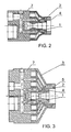
- fig. 3 presents axial section of the extinguishing head including three gas-nozzles and two water-gaps
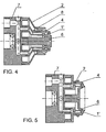
- fig 4 presents axial section of the extinguishing head furnished with two gas-nozzles of annular cross-section including water-nozzles situated parallel to the gas-nozzles axis
- fig. 5 presents axial section of the extinguishing head furnished with two gas-nozzles of annular cross-section and inner water-gap including water-nozzle situated divergently towards to the inner gas-nozzle axis.
- fire extinguishing device is equipped with double-flow extinguishing head including side and central header, water pump P connected to the water tank W1, auxiliary tank W2 including foaming agent proportioning system connected to the water pump P circuit, compressor S, dual-line fire-hose of "hose-in-hose” type and winder K.
- One end of the hose water-line is connected to the side header of the extinguishing head and the other to the water pump P at the delivery side.
- One end of the gas-line is connected to the central header of extinguishing head and the other to the compressor circuit.
- Water pump P is connected to the fire-hose water-line through the first passage of two-way shut-off valve Z4.
- the other passage of this valve is connected, by connecting line, with fire-hose gas-line through the first non-return valve ZZ1 and the foam mixer M .
- Air inlet of designated for compressed foam production foam mixer M is connected to the compressor by a sideline.
- Foam mixer M and gas-line are connected to the circuit of compressor S through shut-off valves Z5, Z6 and the second non-return valve ZZ2 .
- the first gas shut-off valve Z5 is situated on sideline to the foam mixer M and the second gas shut-off valve Z6 is situated on the gas-line between the connecting line and the second non-return valve ZZ2.
- the first non-return valve closes connection of connecting line to the water pump P .
- the second non-return valve ZZ2 closes connection of connecting line with the compressor S .
- a connection with first attachment N1 to connect water tank W1 with water draw point is provided at the suction side of water pump P .
- Other connection to the second attachment N2 provides filling of the auxiliary tank W2.
- Water tank W1 is equipped with filter F.
- Stop valves Z1 and Z2 at the suction side of the water pump P make possible to disconnect a selected tank and its replacement as well as flow control from water tanks W1, W2 to the pump P .
- Non-return valves ZZ1 , ZZ2 protect compressing machinery against undesirable reverse flow effect.
- Main stop valve Z3 is situated at the delivery side of the water pump P .
- Extinguishing head outlet is equipped with a internal gas-nozzle of convergent-divergent profile connected to the central header and also inner water-gap of annular cross-section connected to the side header.
- the headers are connected to separate fire-hose lines.
- Separate delivery ducts are provided in the extinguishing head body 7 to connect side header with respective nozzles at the head outlet.
- Two-position two-way shut-off valve Z4 changeover switch is attached to the head.
- the first position of two-way shut-off valve Z4 opens the first valve passage.
- Extinguishing medium is delivered from the water tank W1 to the extinguishing head through the fire-hose water-line and compressed air is delivered through the gas-line.
- gas-dynamically dispersed water-mist stream is obtained at the extinguishing head outlet.
- a very high dispersion of water particles occurs in the time of extinguishing with water mist, maintaining at the same time compact stream-area of high kinetic energy mist at the head outlet.
- Mass of water mist produced by the extinguishing head consists not only of water mass but also of air mass. Owing to this, kinetic energy of mist produced rises to the extent making possible to direct front of the produced mist stream for a distance of 8-10 m, what is satisfactory distance in fire extinguishing conditions.
- the second position of two-way shut-off valve Z4 directs extinguishing medium from water pump P , through the connecting line, to the foam mixer M from where it is delivered to the fire-hose gas-line.
- the shut-off valve Z1 of the water tank W1 is closed and shut-off valve Z2 of the auxiliary tank W2 with foam producing agent remains open. Compressed foam is produced in the progress of foam mixer M operation.
- the second shut-off valve Z6 is closed. The compressed foam produced flows through the fire-hose gas-line and next the gas-nozzles at the extinguishing head outlet decompress it.
- the extinguishing medium is delivered to the extinguishing head through the gas line and dispersed by the gas-nozzles in the progress of the device operation in the second position of two-way shut-off valve Z4 but with foam mixer M switched-off and shut-off valve Z6 opened.
- the device can be equipped with various extinguishing head execution-versions.
- the fire-hose can be replaced with a system including water and gas-lines to which extinguishing heads are connected.
- the extinguishing head presented at fig. 2 has the body 7 including water and gas header, inner gas-nozzle of convergent-divergent profile and inner water-gap of annular cross-section formed by the sleeve 4 situated coaxially around inner gas-nozzle.
- Inner water-nozzle situated parallel towards to the inner gas-nozzle axis is arranged at the inner water-gap formed by the sleeve 4 .
- the sleeve 4 makes an inner part of the second gas-nozzle 2 of convergent-divergent profile and annular cross-section situated coaxially towards to the inner gas-nozzle.
- End section axis of the gas-nozzle 2 at the divergent nozzle part outlet is situated parallel towards to the inner gas-nozzle axis.
- Circular nozzle 1 makes the inner gas-nozzle.
- Fig. 3 presents realization of the extinguishing nozzle including three gas-nozzles.
- the head is furnished with a circular nozzle 1 and inner water-gap of annular cross-section formed by the sleeve 4 situated coaxially around the circular nozzle 1 .
- the sleeve 4 constitutes an inner part of the second gas-nozzle 2 .
- This nozzle is situated coaxially inside the second sleeve 5 . which forms the outside water-gap of annular cross-section, where the second sleeve 5 makes an inner part of the third gas-nozzle 3 of convergent-divergent profile and situated coaxially towards to the inner gas-nozzle.
- Fig. 4 presents other realization of the head where the inner gas-nozzle makes the first gas-nozzle 1' of annular cross-section and the inner element 6 at the nozzle outlet is ended with conical area that is divergent at about 30° angle towards to the axis of the first gas-nozzle 1' . Additionally the inner water-gap is furnished with a water-nozzle situated parallel towards to the axis of the first gas-nozzle 1' , and final cross-section axis of the second gas-nozzle 2 is divergent at about 30° angle towards to the inner gas-nozzle axis. Connection of the sleeve 4 with the body 7 through an intermediate part 8 is applied in this nozzle.
- Fig. 5 presents other version of the head realization including two situated concentrically gas-nozzles - the first 1' and the second 2 - every of which has the end section axis divergent at about 30° angle towards to the inner gas-nozzle axis and the water-nozzle at the water-gap outlet is divergent at the same angle.
- the inner water-gap of annular cross-section is formed by the sleeve 4 situated coaxially around inner gas-nozzle.
- the inner gas nozzle, formed by the sleeve 4 makes the first gas-nozzle 1' of annular cross-section including coaxially situated inner element 6 .
- Inner element 6 is ended at the nozzle outlet with divergent surface at acute angle towards to the inner gas-nozzle axis.
- Water-gaps outlets can be ended with water-nozzle of the walls parallel to inner gas-nozzle axis or of convergent walls depending on extinguishing heads realization. These nozzles can be situated at an angle from 0° to 45° towards to inner gas-nozzle axis and this angle arm determines the axis of nozzle outlet cross-section in the plane that runs through the inner nozzle axis. Water-gaps in the part before the water-nozzle can be furnished with a swirl chamber that is formed by annular throat or a recess in outside or inner water-gap wall.
- Efficiency of the extinguishing device performance can be increased by application of additives, such as salt solutions and particularly NaCl, in order to raise delivered water density.
- additives such as salt solutions and particularly NaCl
- Introduction of water solutions or other, less volatile than water, substances into the flame area increases flame extinguishing efficiency and evaporated solid particles that remain in the fire area provide additional smothering factor.
- These solutions can be prepared in auxiliary tanks, which can be easily connected to the water pump P at suction side. It is also possible to connect auxiliary tanks at the delivery side with the help of auxiliary water pumps as well as to connect the water pump P directly to the draw point.
- the extinguishing device and extinguishing nozzle according to the invention can be applied in stationary systems of extinguishing devices for the purposes to protect rooms, communication and equipment lines where a determined nozzles system of various reach, dispersion and outflow direction is required. Additionally they can be applied to disperse chemical agents by water mist produced. In this case the device makes possible contaminations neutralising and washing with water in one operation cycle without the necessity to replace the extinguishing head.
Applications Claiming Priority (2)
| Application Number | Priority Date | Filing Date | Title |
|---|---|---|---|
| PL375521A PL204019B1 (pl) | 2005-06-05 | 2005-06-05 | Urządzenie do gaszenia pożarów i głowica gasząca |
| EP06757913A EP1893304B1 (en) | 2005-06-05 | 2006-05-29 | Fire extinguishing device and extinguishing head |
Related Parent Applications (2)
| Application Number | Title | Priority Date | Filing Date |
|---|---|---|---|
| EP06757913A Division EP1893304B1 (en) | 2005-06-05 | 2006-05-29 | Fire extinguishing device and extinguishing head |
| EP06757913.6 Division | 2006-05-29 |
Publications (3)
| Publication Number | Publication Date |
|---|---|
| EP2052760A2 EP2052760A2 (en) | 2009-04-29 |
| EP2052760A3 EP2052760A3 (en) | 2009-07-01 |
| EP2052760B1 true EP2052760B1 (en) | 2010-09-15 |
Family
ID=36950408
Family Applications (2)
| Application Number | Title | Priority Date | Filing Date |
|---|---|---|---|
| EP06757913A Active EP1893304B1 (en) | 2005-06-05 | 2006-05-29 | Fire extinguishing device and extinguishing head |
| EP09075039A Active EP2052760B1 (en) | 2005-06-05 | 2006-05-29 | An extinguishing head |
Family Applications Before (1)
| Application Number | Title | Priority Date | Filing Date |
|---|---|---|---|
| EP06757913A Active EP1893304B1 (en) | 2005-06-05 | 2006-05-29 | Fire extinguishing device and extinguishing head |
Country Status (14)
| Country | Link |
|---|---|
| US (1) | US20100218957A1 (pl) |
| EP (2) | EP1893304B1 (pl) |
| JP (1) | JP4795432B2 (pl) |
| KR (1) | KR101201158B1 (pl) |
| CN (1) | CN101171054B (pl) |
| AT (2) | ATE450297T1 (pl) |
| AU (1) | AU2006255836B2 (pl) |
| CA (1) | CA2609015A1 (pl) |
| DE (2) | DE602006010860D1 (pl) |
| PL (1) | PL204019B1 (pl) |
| RU (1) | RU2388509C2 (pl) |
| UA (1) | UA91225C2 (pl) |
| WO (1) | WO2006132557A1 (pl) |
| ZA (1) | ZA200709785B (pl) |
Families Citing this family (16)
| Publication number | Priority date | Publication date | Assignee | Title |
|---|---|---|---|---|
| US9004375B2 (en) | 2004-02-26 | 2015-04-14 | Tyco Fire & Security Gmbh | Method and apparatus for generating a mist |
| AU2005216699B2 (en) | 2004-02-26 | 2011-07-14 | Tyco Fire & Security Gmbh | Method and apparatus for generating a mist |
| US20080103217A1 (en) | 2006-10-31 | 2008-05-01 | Hari Babu Sunkara | Polyether ester elastomer composition |
| US8419378B2 (en) | 2004-07-29 | 2013-04-16 | Pursuit Dynamics Plc | Jet pump |
| GB0618196D0 (en) | 2006-09-15 | 2006-10-25 | Pursuit Dynamics Plc | An improved mist generating apparatus and method |
| JP4966793B2 (ja) * | 2007-09-10 | 2012-07-04 | 能美防災株式会社 | 消火設備 |
| US10532237B2 (en) * | 2010-08-05 | 2020-01-14 | Victaulic Company | Dual mode agent discharge system with multiple agent discharge capability |
| CN102327683A (zh) * | 2011-07-27 | 2012-01-25 | 江苏中瑞电保智能装备有限公司 | 嵌套式喷嘴 |
| CN102335491B (zh) * | 2011-07-27 | 2013-07-10 | 江苏中瑞电保智能装备有限公司 | 管网式干粉灭火系统及方法 |
| RU2478437C1 (ru) * | 2011-10-10 | 2013-04-10 | Олег Савельевич Кочетов | Газоводяная система пожаротушения кочетова |
| RU2494779C1 (ru) * | 2012-09-20 | 2013-10-10 | Олег Савельевич Кочетов | Пеногенератор вихревого типа |
| KR101666036B1 (ko) * | 2016-03-17 | 2016-10-14 | 주식회사 엠티케이방재시스템 | 압축공기포 혼합장치 |
| RU2625137C1 (ru) * | 2016-06-10 | 2017-07-11 | Олег Савельевич Кочетов | Резервуар для хранения жидких грузов |
| RU2641272C1 (ru) * | 2017-02-27 | 2018-01-16 | Олег Савельевич Кочетов | Генератор полидисперсной высокократной пены вихревого типа |
| RU2642582C1 (ru) * | 2017-02-27 | 2018-01-25 | Олег Савельевич Кочетов | Пеногенератор |
| RU2664060C1 (ru) * | 2017-12-28 | 2018-08-14 | Олег Савельевич Кочетов | Генератор полидисперсной высокократной пены вихревого типа |
Family Cites Families (21)
| Publication number | Priority date | Publication date | Assignee | Title |
|---|---|---|---|---|
| US501164A (en) * | 1893-07-11 | Benjamin roberts | ||
| US1358084A (en) * | 1918-12-18 | 1920-11-09 | Submarine Signal Co | Method of producing fog-screens |
| DE857924C (de) * | 1949-06-03 | 1952-12-04 | Emil Dr-Ing Kirschbaum | Zerstaeubungsduese |
| GB998490A (en) | 1961-06-03 | 1965-07-14 | Albert Fritz Albach | A foam projector |
| US3115158A (en) * | 1962-03-01 | 1963-12-24 | Sterling Prec Corp | Airfoam liquid proportioning system |
| FR2522393B1 (fr) * | 1982-02-26 | 1990-02-02 | Chugai Ro Kogyo Kaisha Ltd | Bruleur de combustible liquide a reglage par action proportionnelle |
| CN2073311U (zh) * | 1989-12-30 | 1991-03-20 | 王虎儒 | 水力空气泡沫灭火装置 |
| US5261602A (en) * | 1991-12-23 | 1993-11-16 | Texaco Inc. | Partial oxidation process and burner with porous tip |
| US5255747A (en) * | 1992-10-01 | 1993-10-26 | Hale Fire Pump Company | Compressed air foam system |
| EP0608140A3 (en) * | 1993-01-22 | 1995-12-13 | Cca Inc | Mechanical foam fire fighting equipment and method. |
| US5494112A (en) * | 1993-10-29 | 1996-02-27 | Hypro Corporation | System for introduction of concentrated liquid chemical foamant into a water stream for fighting fires |
| GB9326367D0 (en) * | 1993-12-23 | 1994-02-23 | Rolls Royce Plc | Fuel injection apparatus |
| JPH08266677A (ja) * | 1995-03-31 | 1996-10-15 | Nohmi Bosai Ltd | 消火薬剤複合噴射ノズル |
| DE29510976U1 (de) * | 1995-07-12 | 1995-08-31 | Broemme Albrecht Dipl Ing | Kombiniertes Mehrstoffstrahlrohr |
| US5779158A (en) * | 1996-04-16 | 1998-07-14 | National Foam, Inc. | Nozzle for use with fire-fighting foams |
| US5941459A (en) * | 1997-07-01 | 1999-08-24 | Texaco Inc | Fuel injector nozzle with protective refractory insert |
| DK174899B1 (da) | 1997-12-19 | 2004-02-09 | Firexpress Aps | Brandslukningsindretning |
| DE29811105U1 (de) | 1998-01-22 | 1998-09-10 | Vigh Andreas Dipl Ing Fh | Stufenloses automatisch-mechanisches Schaum-Dosiersystem für Hoch- und Normaldruck-Feuerlöschkreiselpumpen |
| CA2332678A1 (en) | 2000-01-31 | 2001-07-31 | Melody M. Brooks | Fire hose system having actively controllable multi-channel fire hose |
| JP4621337B2 (ja) * | 2000-07-05 | 2011-01-26 | ヤマトプロテック株式会社 | 消火用ノズル及び消火方法 |
| FI20011787A (fi) | 2001-09-10 | 2003-03-11 | Marioff Corp Oy | Menetelmä suihkutuspäässä ja suihkutuspää |
-
2005
- 2005-06-05 PL PL375521A patent/PL204019B1/pl not_active IP Right Cessation
-
2006
- 2006-05-29 UA UAA200713881A patent/UA91225C2/ru unknown
- 2006-05-29 JP JP2008515648A patent/JP4795432B2/ja not_active Expired - Fee Related
- 2006-05-29 WO PCT/PL2006/000037 patent/WO2006132557A1/en active Application Filing
- 2006-05-29 RU RU2007144685/12A patent/RU2388509C2/ru active
- 2006-05-29 US US11/916,656 patent/US20100218957A1/en not_active Abandoned
- 2006-05-29 KR KR1020077027086A patent/KR101201158B1/ko active IP Right Grant
- 2006-05-29 DE DE602006010860T patent/DE602006010860D1/de active Active
- 2006-05-29 CN CN2006800151541A patent/CN101171054B/zh active Active
- 2006-05-29 CA CA002609015A patent/CA2609015A1/en not_active Abandoned
- 2006-05-29 AT AT06757913T patent/ATE450297T1/de not_active IP Right Cessation
- 2006-05-29 AT AT09075039T patent/ATE481138T1/de not_active IP Right Cessation
- 2006-05-29 EP EP06757913A patent/EP1893304B1/en active Active
- 2006-05-29 AU AU2006255836A patent/AU2006255836B2/en not_active Ceased
- 2006-05-29 DE DE602006017003T patent/DE602006017003D1/de active Active
- 2006-05-29 EP EP09075039A patent/EP2052760B1/en active Active
-
2007
- 2007-11-08 ZA ZA200709785A patent/ZA200709785B/xx unknown
Also Published As
| Publication number | Publication date |
|---|---|
| ATE450297T1 (de) | 2009-12-15 |
| UA91225C2 (ru) | 2010-07-12 |
| ZA200709785B (en) | 2008-11-26 |
| KR101201158B1 (ko) | 2012-11-13 |
| US20100218957A1 (en) | 2010-09-02 |
| DE602006017003D1 (de) | 2010-10-28 |
| JP4795432B2 (ja) | 2011-10-19 |
| RU2007144685A (ru) | 2009-07-20 |
| DE602006010860D1 (de) | 2010-01-14 |
| WO2006132557A9 (en) | 2007-12-06 |
| WO2006132557A1 (en) | 2006-12-14 |
| EP1893304A1 (en) | 2008-03-05 |
| EP2052760A2 (en) | 2009-04-29 |
| RU2388509C2 (ru) | 2010-05-10 |
| CA2609015A1 (en) | 2006-12-14 |
| AU2006255836A1 (en) | 2006-12-14 |
| AU2006255836B2 (en) | 2011-09-08 |
| CN101171054A (zh) | 2008-04-30 |
| PL375521A1 (pl) | 2006-12-11 |
| CN101171054B (zh) | 2011-10-12 |
| PL204019B1 (pl) | 2009-12-31 |
| JP2008541984A (ja) | 2008-11-27 |
| KR20080012882A (ko) | 2008-02-12 |
| ATE481138T1 (de) | 2010-10-15 |
| EP2052760A3 (en) | 2009-07-01 |
| EP1893304B1 (en) | 2009-12-02 |
Similar Documents
| Publication | Publication Date | Title |
|---|---|---|
| EP2052760B1 (en) | An extinguishing head | |
| AU2018226928B2 (en) | Foam production method, fire extinguishing method, and foam extinguishing appliance | |
| US5427181A (en) | Mixer for compressed air foam system | |
| US6425537B1 (en) | Fire extinguishing device | |
| CA2567657C (en) | Water mist generating head | |
| CA2668587A1 (en) | Dual extinguishment fire suppression system using high velocity low pressure emitters | |
| CN115350427B (zh) | 消防泡沫发泡器、系统以及发泡方法 | |
| CA3034985A1 (en) | High velocity spray torch for spraying internal surfaces | |
| US20170259091A1 (en) | Fire-fighting system | |
| CN115350426B (zh) | 消防泡沫发泡装置、系统以及发泡方法 | |
| RU2713249C1 (ru) | Генератор воздушно-механической пены средней и низкой кратности для лафетного ствола и лафетный ствол с генератором воздушно-механической пены средней и низкой кратности | |
| RU192064U1 (ru) | Генератор воздушномеханической пены средней и низкой кратности для лафетного ствола | |
| US5893519A (en) | Self-educting, high expansion, multi-agent nozzle | |
| US11980785B2 (en) | Foam producing method, fire extinguishing method, and appliance for foam extinguishing | |
| RU2404832C1 (ru) | Пеногенератор эжекционного типа | |
| RU2300424C1 (ru) | Распылитель | |
| US2216072A (en) | Method of extinguishing fires | |
| US9370675B1 (en) | Foam generating apparatus and method for compressed air foam systems | |
| RU2489187C2 (ru) | Устройство пожаротушения тонкораспыленным потоком огнетушащей жидкости или потоком пены и распылитель для их формирования | |
| RU113967U1 (ru) | Устройство пожаротушения тонкораспыленным потоком огнетушащей жидкости или потоком пены и распылитель для их формирования | |
| GB2293762A (en) | Extinguishing fires |
Legal Events
| Date | Code | Title | Description |
|---|---|---|---|
| PUAI | Public reference made under article 153(3) epc to a published international application that has entered the european phase |
Free format text: ORIGINAL CODE: 0009012 |
|
| AC | Divisional application: reference to earlier application |
Ref document number: 1893304 Country of ref document: EP Kind code of ref document: P |
|
| AK | Designated contracting states |
Kind code of ref document: A2 Designated state(s): AT BE BG CH CY CZ DE DK EE ES FI FR GB GR HU IE IS IT LI LT LU LV MC NL PL PT RO SE SI SK TR |
|
| AX | Request for extension of the european patent |
Extension state: AL BA HR MK YU |
|
| PUAL | Search report despatched |
Free format text: ORIGINAL CODE: 0009013 |
|
| AK | Designated contracting states |
Kind code of ref document: A3 Designated state(s): AT BE BG CH CY CZ DE DK EE ES FI FR GB GR HU IE IS IT LI LT LU LV MC NL PL PT RO SE SI SK TR |
|
| AX | Request for extension of the european patent |
Extension state: AL BA HR MK YU |
|
| RIC1 | Information provided on ipc code assigned before grant |
Ipc: A62C 31/07 20060101AFI20090528BHEP |
|
| 17P | Request for examination filed |
Effective date: 20091216 |
|
| GRAP | Despatch of communication of intention to grant a patent |
Free format text: ORIGINAL CODE: EPIDOSNIGR1 |
|
| AKX | Designation fees paid |
Designated state(s): AT BE BG CH CY CZ DE DK EE ES FI FR GB GR HU IE IS IT LI LT LU LV MC NL PL PT RO SE SI SK TR |
|
| GRAS | Grant fee paid |
Free format text: ORIGINAL CODE: EPIDOSNIGR3 |
|
| GRAA | (expected) grant |
Free format text: ORIGINAL CODE: 0009210 |
|
| AC | Divisional application: reference to earlier application |
Ref document number: 1893304 Country of ref document: EP Kind code of ref document: P |
|
| AK | Designated contracting states |
Kind code of ref document: B1 Designated state(s): AT BE BG CH CY CZ DE DK EE ES FI FR GB GR HU IE IS IT LI LT LU LV MC NL PL PT RO SE SI SK TR |
|
| REG | Reference to a national code |
Ref country code: GB Ref legal event code: FG4D Ref country code: CH Ref legal event code: EP |
|
| REG | Reference to a national code |
Ref country code: IE Ref legal event code: FG4D |
|
| REF | Corresponds to: |
Ref document number: 602006017003 Country of ref document: DE Date of ref document: 20101028 Kind code of ref document: P |
|
| REG | Reference to a national code |
Ref country code: NL Ref legal event code: VDEP Effective date: 20100915 |
|
| PG25 | Lapsed in a contracting state [announced via postgrant information from national office to epo] |
Ref country code: FI Free format text: LAPSE BECAUSE OF FAILURE TO SUBMIT A TRANSLATION OF THE DESCRIPTION OR TO PAY THE FEE WITHIN THE PRESCRIBED TIME-LIMIT Effective date: 20100915 Ref country code: AT Free format text: LAPSE BECAUSE OF FAILURE TO SUBMIT A TRANSLATION OF THE DESCRIPTION OR TO PAY THE FEE WITHIN THE PRESCRIBED TIME-LIMIT Effective date: 20100915 Ref country code: LT Free format text: LAPSE BECAUSE OF FAILURE TO SUBMIT A TRANSLATION OF THE DESCRIPTION OR TO PAY THE FEE WITHIN THE PRESCRIBED TIME-LIMIT Effective date: 20100915 |
|
| LTIE | Lt: invalidation of european patent or patent extension |
Effective date: 20100915 |
|
| PG25 | Lapsed in a contracting state [announced via postgrant information from national office to epo] |
Ref country code: CY Free format text: LAPSE BECAUSE OF FAILURE TO SUBMIT A TRANSLATION OF THE DESCRIPTION OR TO PAY THE FEE WITHIN THE PRESCRIBED TIME-LIMIT Effective date: 20100915 Ref country code: PL Free format text: LAPSE BECAUSE OF FAILURE TO SUBMIT A TRANSLATION OF THE DESCRIPTION OR TO PAY THE FEE WITHIN THE PRESCRIBED TIME-LIMIT Effective date: 20100915 Ref country code: SI Free format text: LAPSE BECAUSE OF FAILURE TO SUBMIT A TRANSLATION OF THE DESCRIPTION OR TO PAY THE FEE WITHIN THE PRESCRIBED TIME-LIMIT Effective date: 20100915 |
|
| PG25 | Lapsed in a contracting state [announced via postgrant information from national office to epo] |
Ref country code: GR Free format text: LAPSE BECAUSE OF FAILURE TO SUBMIT A TRANSLATION OF THE DESCRIPTION OR TO PAY THE FEE WITHIN THE PRESCRIBED TIME-LIMIT Effective date: 20101216 Ref country code: LV Free format text: LAPSE BECAUSE OF FAILURE TO SUBMIT A TRANSLATION OF THE DESCRIPTION OR TO PAY THE FEE WITHIN THE PRESCRIBED TIME-LIMIT Effective date: 20100915 Ref country code: SE Free format text: LAPSE BECAUSE OF FAILURE TO SUBMIT A TRANSLATION OF THE DESCRIPTION OR TO PAY THE FEE WITHIN THE PRESCRIBED TIME-LIMIT Effective date: 20100915 |
|
| PG25 | Lapsed in a contracting state [announced via postgrant information from national office to epo] |
Ref country code: CZ Free format text: LAPSE BECAUSE OF FAILURE TO SUBMIT A TRANSLATION OF THE DESCRIPTION OR TO PAY THE FEE WITHIN THE PRESCRIBED TIME-LIMIT Effective date: 20100915 Ref country code: PT Free format text: LAPSE BECAUSE OF FAILURE TO SUBMIT A TRANSLATION OF THE DESCRIPTION OR TO PAY THE FEE WITHIN THE PRESCRIBED TIME-LIMIT Effective date: 20110117 Ref country code: IT Free format text: LAPSE BECAUSE OF FAILURE TO SUBMIT A TRANSLATION OF THE DESCRIPTION OR TO PAY THE FEE WITHIN THE PRESCRIBED TIME-LIMIT Effective date: 20100915 Ref country code: NL Free format text: LAPSE BECAUSE OF FAILURE TO SUBMIT A TRANSLATION OF THE DESCRIPTION OR TO PAY THE FEE WITHIN THE PRESCRIBED TIME-LIMIT Effective date: 20100915 Ref country code: SK Free format text: LAPSE BECAUSE OF FAILURE TO SUBMIT A TRANSLATION OF THE DESCRIPTION OR TO PAY THE FEE WITHIN THE PRESCRIBED TIME-LIMIT Effective date: 20100915 Ref country code: IS Free format text: LAPSE BECAUSE OF FAILURE TO SUBMIT A TRANSLATION OF THE DESCRIPTION OR TO PAY THE FEE WITHIN THE PRESCRIBED TIME-LIMIT Effective date: 20110115 Ref country code: EE Free format text: LAPSE BECAUSE OF FAILURE TO SUBMIT A TRANSLATION OF THE DESCRIPTION OR TO PAY THE FEE WITHIN THE PRESCRIBED TIME-LIMIT Effective date: 20100915 Ref country code: RO Free format text: LAPSE BECAUSE OF FAILURE TO SUBMIT A TRANSLATION OF THE DESCRIPTION OR TO PAY THE FEE WITHIN THE PRESCRIBED TIME-LIMIT Effective date: 20100915 |
|
| PG25 | Lapsed in a contracting state [announced via postgrant information from national office to epo] |
Ref country code: BE Free format text: LAPSE BECAUSE OF FAILURE TO SUBMIT A TRANSLATION OF THE DESCRIPTION OR TO PAY THE FEE WITHIN THE PRESCRIBED TIME-LIMIT Effective date: 20100915 Ref country code: ES Free format text: LAPSE BECAUSE OF FAILURE TO SUBMIT A TRANSLATION OF THE DESCRIPTION OR TO PAY THE FEE WITHIN THE PRESCRIBED TIME-LIMIT Effective date: 20101226 |
|
| PLBE | No opposition filed within time limit |
Free format text: ORIGINAL CODE: 0009261 |
|
| STAA | Information on the status of an ep patent application or granted ep patent |
Free format text: STATUS: NO OPPOSITION FILED WITHIN TIME LIMIT |
|
| 26N | No opposition filed |
Effective date: 20110616 |
|
| PG25 | Lapsed in a contracting state [announced via postgrant information from national office to epo] |
Ref country code: DK Free format text: LAPSE BECAUSE OF FAILURE TO SUBMIT A TRANSLATION OF THE DESCRIPTION OR TO PAY THE FEE WITHIN THE PRESCRIBED TIME-LIMIT Effective date: 20100915 |
|
| REG | Reference to a national code |
Ref country code: DE Ref legal event code: R097 Ref document number: 602006017003 Country of ref document: DE Effective date: 20110616 |
|
| PG25 | Lapsed in a contracting state [announced via postgrant information from national office to epo] |
Ref country code: MC Free format text: LAPSE BECAUSE OF NON-PAYMENT OF DUE FEES Effective date: 20110531 |
|
| REG | Reference to a national code |
Ref country code: CH Ref legal event code: PL |
|
| PG25 | Lapsed in a contracting state [announced via postgrant information from national office to epo] |
Ref country code: CH Free format text: LAPSE BECAUSE OF NON-PAYMENT OF DUE FEES Effective date: 20110531 Ref country code: LI Free format text: LAPSE BECAUSE OF NON-PAYMENT OF DUE FEES Effective date: 20110531 |
|
| REG | Reference to a national code |
Ref country code: IE Ref legal event code: MM4A |
|
| PG25 | Lapsed in a contracting state [announced via postgrant information from national office to epo] |
Ref country code: IE Free format text: LAPSE BECAUSE OF NON-PAYMENT OF DUE FEES Effective date: 20110529 |
|
| PG25 | Lapsed in a contracting state [announced via postgrant information from national office to epo] |
Ref country code: LU Free format text: LAPSE BECAUSE OF NON-PAYMENT OF DUE FEES Effective date: 20110529 |
|
| PG25 | Lapsed in a contracting state [announced via postgrant information from national office to epo] |
Ref country code: BG Free format text: LAPSE BECAUSE OF FAILURE TO SUBMIT A TRANSLATION OF THE DESCRIPTION OR TO PAY THE FEE WITHIN THE PRESCRIBED TIME-LIMIT Effective date: 20101215 Ref country code: TR Free format text: LAPSE BECAUSE OF FAILURE TO SUBMIT A TRANSLATION OF THE DESCRIPTION OR TO PAY THE FEE WITHIN THE PRESCRIBED TIME-LIMIT Effective date: 20100915 |
|
| PG25 | Lapsed in a contracting state [announced via postgrant information from national office to epo] |
Ref country code: HU Free format text: LAPSE BECAUSE OF FAILURE TO SUBMIT A TRANSLATION OF THE DESCRIPTION OR TO PAY THE FEE WITHIN THE PRESCRIBED TIME-LIMIT Effective date: 20100915 |
|
| REG | Reference to a national code |
Ref country code: FR Ref legal event code: PLFP Year of fee payment: 10 |
|
| REG | Reference to a national code |
Ref country code: FR Ref legal event code: PLFP Year of fee payment: 11 |
|
| REG | Reference to a national code |
Ref country code: FR Ref legal event code: PLFP Year of fee payment: 12 |
|
| REG | Reference to a national code |
Ref country code: FR Ref legal event code: PLFP Year of fee payment: 13 |
|
| PGFP | Annual fee paid to national office [announced via postgrant information from national office to epo] |
Ref country code: GB Payment date: 20220520 Year of fee payment: 17 Ref country code: FR Payment date: 20220523 Year of fee payment: 17 Ref country code: DE Payment date: 20220519 Year of fee payment: 17 |
|
| REG | Reference to a national code |
Ref country code: DE Ref legal event code: R119 Ref document number: 602006017003 Country of ref document: DE |
|
| GBPC | Gb: european patent ceased through non-payment of renewal fee |
Effective date: 20230529 |
|
| PG25 | Lapsed in a contracting state [announced via postgrant information from national office to epo] |
Ref country code: DE Free format text: LAPSE BECAUSE OF NON-PAYMENT OF DUE FEES Effective date: 20231201 Ref country code: GB Free format text: LAPSE BECAUSE OF NON-PAYMENT OF DUE FEES Effective date: 20230529 |