EP2052236B1 - Optical sensing system and method for discriminating plant matter - Google Patents
Optical sensing system and method for discriminating plant matter Download PDFInfo
- Publication number
- EP2052236B1 EP2052236B1 EP07784717A EP07784717A EP2052236B1 EP 2052236 B1 EP2052236 B1 EP 2052236B1 EP 07784717 A EP07784717 A EP 07784717A EP 07784717 A EP07784717 A EP 07784717A EP 2052236 B1 EP2052236 B1 EP 2052236B1
- Authority
- EP
- European Patent Office
- Prior art keywords
- wavelengths
- light
- plant matter
- laser
- combined
- Prior art date
- Legal status (The legal status is an assumption and is not a legal conclusion. Google has not performed a legal analysis and makes no representation as to the accuracy of the status listed.)
- Active
Links
- 230000003287 optical effect Effects 0.000 title claims description 18
- 238000000034 method Methods 0.000 title claims description 11
- 230000007423 decrease Effects 0.000 claims description 2
- 241000196324 Embryophyta Species 0.000 description 19
- 238000000576 coating method Methods 0.000 description 14
- 239000011248 coating agent Substances 0.000 description 13
- 239000007921 spray Substances 0.000 description 10
- 238000010586 diagram Methods 0.000 description 8
- 235000013399 edible fruits Nutrition 0.000 description 5
- 239000000126 substance Substances 0.000 description 5
- 241000238631 Hexapoda Species 0.000 description 4
- 241001464837 Viridiplantae Species 0.000 description 3
- 241000607479 Yersinia pestis Species 0.000 description 3
- 238000001514 detection method Methods 0.000 description 3
- 239000011521 glass Substances 0.000 description 3
- 230000008569 process Effects 0.000 description 3
- 239000000758 substrate Substances 0.000 description 3
- 239000010409 thin film Substances 0.000 description 3
- 235000013311 vegetables Nutrition 0.000 description 3
- 238000004458 analytical method Methods 0.000 description 2
- 239000004009 herbicide Substances 0.000 description 2
- 238000003384 imaging method Methods 0.000 description 2
- 239000002243 precursor Substances 0.000 description 2
- 238000002310 reflectometry Methods 0.000 description 2
- 239000002689 soil Substances 0.000 description 2
- 238000001228 spectrum Methods 0.000 description 2
- 238000005507 spraying Methods 0.000 description 2
- 244000141359 Malus pumila Species 0.000 description 1
- 230000009471 action Effects 0.000 description 1
- 239000003905 agrochemical Substances 0.000 description 1
- 235000021016 apples Nutrition 0.000 description 1
- 230000005540 biological transmission Effects 0.000 description 1
- 238000004422 calculation algorithm Methods 0.000 description 1
- 238000004364 calculation method Methods 0.000 description 1
- 238000006243 chemical reaction Methods 0.000 description 1
- 239000003086 colorant Substances 0.000 description 1
- 238000004737 colorimetric analysis Methods 0.000 description 1
- 230000000295 complement effect Effects 0.000 description 1
- 239000002131 composite material Substances 0.000 description 1
- 238000004590 computer program Methods 0.000 description 1
- 230000001627 detrimental effect Effects 0.000 description 1
- 230000007613 environmental effect Effects 0.000 description 1
- 238000011156 evaluation Methods 0.000 description 1
- 238000009313 farming Methods 0.000 description 1
- 230000002363 herbicidal effect Effects 0.000 description 1
- 238000005286 illumination Methods 0.000 description 1
- 238000002329 infrared spectrum Methods 0.000 description 1
- 239000002917 insecticide Substances 0.000 description 1
- 238000004519 manufacturing process Methods 0.000 description 1
- 239000000463 material Substances 0.000 description 1
- 238000012986 modification Methods 0.000 description 1
- 230000004048 modification Effects 0.000 description 1
- 239000004033 plastic Substances 0.000 description 1
- 229920003023 plastic Polymers 0.000 description 1
- 238000007781 pre-processing Methods 0.000 description 1
- 230000009467 reduction Effects 0.000 description 1
- 238000000985 reflectance spectrum Methods 0.000 description 1
- 230000004044 response Effects 0.000 description 1
- 230000003595 spectral effect Effects 0.000 description 1
- 238000010408 sweeping Methods 0.000 description 1
- 238000001429 visible spectrum Methods 0.000 description 1
Images

Classifications
-
- G—PHYSICS
- G01—MEASURING; TESTING
- G01N—INVESTIGATING OR ANALYSING MATERIALS BY DETERMINING THEIR CHEMICAL OR PHYSICAL PROPERTIES
- G01N21/00—Investigating or analysing materials by the use of optical means, i.e. using sub-millimetre waves, infrared, visible or ultraviolet light
- G01N21/17—Systems in which incident light is modified in accordance with the properties of the material investigated
- G01N21/25—Colour; Spectral properties, i.e. comparison of effect of material on the light at two or more different wavelengths or wavelength bands
- G01N21/255—Details, e.g. use of specially adapted sources, lighting or optical systems
-
- A—HUMAN NECESSITIES
- A01—AGRICULTURE; FORESTRY; ANIMAL HUSBANDRY; HUNTING; TRAPPING; FISHING
- A01M—CATCHING, TRAPPING OR SCARING OF ANIMALS; APPARATUS FOR THE DESTRUCTION OF NOXIOUS ANIMALS OR NOXIOUS PLANTS
- A01M21/00—Apparatus for the destruction of unwanted vegetation, e.g. weeds
-
- G—PHYSICS
- G01—MEASURING; TESTING
- G01N—INVESTIGATING OR ANALYSING MATERIALS BY DETERMINING THEIR CHEMICAL OR PHYSICAL PROPERTIES
- G01N21/00—Investigating or analysing materials by the use of optical means, i.e. using sub-millimetre waves, infrared, visible or ultraviolet light
- G01N21/17—Systems in which incident light is modified in accordance with the properties of the material investigated
- G01N2021/1793—Remote sensing
- G01N2021/1797—Remote sensing in landscape, e.g. crops
-
- G—PHYSICS
- G01—MEASURING; TESTING
- G01N—INVESTIGATING OR ANALYSING MATERIALS BY DETERMINING THEIR CHEMICAL OR PHYSICAL PROPERTIES
- G01N21/00—Investigating or analysing materials by the use of optical means, i.e. using sub-millimetre waves, infrared, visible or ultraviolet light
- G01N21/84—Systems specially adapted for particular applications
- G01N2021/8466—Investigation of vegetal material, e.g. leaves, plants, fruits
-
- G—PHYSICS
- G01—MEASURING; TESTING
- G01N—INVESTIGATING OR ANALYSING MATERIALS BY DETERMINING THEIR CHEMICAL OR PHYSICAL PROPERTIES
- G01N2201/00—Features of devices classified in G01N21/00
- G01N2201/06—Illumination; Optics
- G01N2201/069—Supply of sources
- G01N2201/0691—Modulated (not pulsed supply)
-
- G—PHYSICS
- G01—MEASURING; TESTING
- G01N—INVESTIGATING OR ANALYSING MATERIALS BY DETERMINING THEIR CHEMICAL OR PHYSICAL PROPERTIES
- G01N2201/00—Features of devices classified in G01N21/00
- G01N2201/06—Illumination; Optics
- G01N2201/069—Supply of sources
- G01N2201/0696—Pulsed
Definitions
- the present invention relates to optical devices and use of optical devices in a sensor for identifying objects.
- Such discrimination can be, for example, plant discrimination for horticultural purposes, foreign object detection in industrial processes and in classification systems, to name just a few.
- Pests may include insects or weeds.
- weed control it is common practice to spray herbicides at different times in the cultivation cycle of a crop.
- Environmental concerns and increased farm costs have led to critical evaluation of the use of chemicals in agriculture.
- Some farming practices have emerged which enable site specific application of chemicals such as herbicide, hence limiting the use of agro-chemicals.
- the ability to accurately identify and/or differentiate plants in real time and at common operating speeds of farm equipment is regarded as an unmet desire in agriculture.
- the Patchen Weed Seeker discriminates by measuring the vegetation index (VI) defined as the ratio of reflection at near infrared wavelengths (at around 800nm) to reflection at red wavelengths (around 650nm).
- VI vegetation index
- This system still has numerous problems including focusing of light from its LED light sources when the target object varies in distance from the LEDs and its ability to discriminate between different green plants with any reliability.
- US 5673113 A1 discloses an analysis device for the automatic grading of fruits or vegetables with respect to quality and to coloration - with regard to the details of the processing performed by the processing unit US 5673113 refers to explicitly to FR 2703932 A1 .
- the device according to US 5673113 comprises a first assembly having a multi-line laser source 4 whose beam is delivered by means of a deviation mirror 5 towards a polarising cube 6 (for distinguishing outgoing and incoming beams) and collection means 7 described in FR2703932 which include a detector.
- the device further comprises a second assembly having a laser source 8 composed of an infrared collimated laser diode whose beam is delivered via a deviation mirror 9 towards polarising cube 10 - collection means at 11 similar to collection means 7 are also provided.
- the device further comprises a third assembly composed of a collimated infrared laser diode 12 whose beam is delivered via a deviation mirror 13 towards a polarising cube 14 - collection chain 15 including a detector are also provided.
- the device also comprises dichroic blades 16-18 proximate respectively to each of the three light sources 4, 8 and 12 for deflecting respectively wavelengths of less than 700 nanometres, wavelengths of less than 800 nanometres and wavelengths of less than 1 micron to generate a superimposed beam which is delivered towards a rotating polygon 19 and an assembly of mirrors 20-29 for subsequent sweeping of the composite beam over the samples vegetables or fruit which are transported on two conveying lines 2, 3.
- the reflected light is detected by the respective detectors in the collection means 7, 11, 15 whose output signals are input to a processing unit detailed in FR2703932 comprising analog/numeric conversion means and calculation means suited to calculating, on the basis of pre-defined programmed criteria, usable items of grading information whereby the generated colorimetric data is used in the automatic colorimetric sorting of the fruits or vegetables (in addition a pre-processing is performed in which the detection of a concave concave-shaped discontinuity in the reflected light at all wavelengths results in the colorimetric analysis not being carried out for such points).
- the colorimetric processing algorithm consists of storing, initially, for each wavelength, the values of the gray levels (0 to 255) of all the points. The subsequent steps depend on the fruit to be graded and the predominant colors in the latter, and can be adapted to each type of fruit e.g. for apples, the colorimetric spectra between green and blue and between red and green are calculated for each point.
- the present invention comprises a sensing system as defined in appended claim 1.
- the present invention comprises a method of identification of plant matter as defined in appended claim 10.
- collimated is used to mean a narrow beam with minimal divergence over the useful length of the beam when used in applications suitable for the present invention.
- wavelength is used to define a characteristic of light.
- Figure 1 shows a sensing and spraying system 10 which comprises a sensing component 12, a controller 22 and a controllable spray unit 24.
- the system 10 is typically attached to a boom of a piece of farm machinery (such as a tractor) and travels over a crop in a field being cultivated. The direction of travel would be right to left of the diagram.
- the field has plants 28 of the crop which grow from the ground 30 and unwanted plants, hereafter referred to as weeds 26.
- the system 10 needs to be able to distinguish not only the ground 30 from the crop 28, but in particular needs to distinguish the weeds 26 from the crop 28.
- the system may be designed to detect other pests such as insects.
- the system 10 operates by producing at least one beam of light 16 from a light source 14 of the sensing component 12.
- the light beam 16 is directed at objects within a field of view as it moves over the field.
- the transmitted beam 16 is reflected off objects, and in this case a weed 26, to produce a reflected beam 18.
- a sensor unit 20 of the sensing component 12 detects the reflected beam 18.
- Measured reflectance data from the sensor unit 20 is sent to the controller 22, which processes the data to identify the object being scanned by the beam 16.
- the controller 22 is further arranged to control the spray unit 24 so that at the time the spray unit 24 passes over the weed 26, a valve in the spray unit 24 can be operated so as to spray the weed 26 with a suitable chemical, thereby only using the chemical as required.
- the identification process undertaken by the controller 22 is described below.
- the vegetation index is defined as the ratio of reflection at near infrared wavelength (around 800nm) to the reflection at red wavelengths (around 650nm). It has been discovered by the inventor that the use of additional wavelengths provides additional ability to discriminate not only plants from soil but also the ability to discriminate between different types of green plant, for which the prior art vegetation index is not reliable.
- the present invention achieves this by the light source 14 producing light at three or more different wavelengths. It is desirable to use lasers as the source of light as they are well suited to producing light having very narrow bandwidths. A laser can be regarded as producing light at only the desired wavelength. Each individual laser will produce light at each individual wavelength in an individual beam. In the past complex optics have been used to try to aim light (whether from a laser or not) at a single point having a varying distance from the light source. The inventor has overcome this problem by combining the individual beams into a single combined beam. An example achieves this by use of a collimator described further below.
- the light source 14 comprises a laser array 30, a WDM combiner, a collimator 32, which respectively combine and collimate the laser beams from each laser into a single combined, collimated beam 48 and a beam splitter 34 which splits the combined, collimated beam 48 into a plurality of parallel beams 16 directed at objects in the field of view.
- An alternative to use of the beam splitter is to scan the beam 16 across a path by moving a reflector so as to direct the beam across the path.
- the beam 16 may be pulsed so as to illuminate spots as it traverses the path or it may be continuous.
- laser array comprises three AC-driven laser diodes, each producing light at a different wavelength (630nm, 670nm and 780nm).
- the laser diodes are individually controllable by the controller 22 via a control circuit.
- the intensity of the beam emitted by each laser can be controlled by a trim-pot.
- the WDM beams are overlapped by the WDM combiner and collimated by the collimator 32.
- the combined, collimated beam 48 has a diameter of 5mm.
- the beam 16 will usually be pulsed/modulated so that upon demodulation the intensity of the reflected beam 18 can distinguished from any background light.
- the beam splitter 34 comprises an elongate optical cavity 40, formed of a suitable material, such as glass or clear plastics.
- the optical cavity 40 could also be formed of a hollow inside of a prism.
- the cavity 40 has a rectangular prism shape with opposite ends 44 and 46, and parallel, opposite longitudinal sides 36 and 38. It also has an optical inlet 42 into which the combined beam 48 can enter the cavity 40.
- the inlet 42 is positioned at or near the end 44.
- a highly reflective coating is applied to the surface of the side 36, which ideally has a reflectance greater than 99%.
- a partially reflective coating is applied to the second side 38, which reflects approximately 90% of light and transmits approximately 10% of light striking it. This enables the majority of the beam 48 striking the coating to be reflected while allowing some of it to be transmitted.
- the incoming combined beam 48 Due to the angle of incidence of the incoming combined beam 48 it reflects between the surface coatings of sides 36 and 38, while at the same time producing a series of parallel beams 16, which are emitted from the side 38.
- the reflectivity of the coating on the side 38 in this embodiment is constant, but due to the intensity being progressively degraded by each beam transmitted, the internally reflected beam intensity will progressively decrease as it propagates along the length of the cavity 40. This in turn will produce progressively less intense beams 16 further away from the inlet 42 towards the second end 46.
- the reflectivity/transmissibility of the coating of side 38 need not be constant along the length of the cavity 40 and need not be 90%/10%.
- An angle of incidence of the combined beam 48 into the cavity will determined the number of times the beam will be reflected down the length of the cavity 40, which in turn will determine the spacing between each output beam 16.
- the splitter 34 comprises an optical cavity which is a single glass substrate in the shape of a rectangular prism of dimensions 199mm x 29mm x 14mm, approximately.
- the ends may be uncoated (clear) so that one can perform as the optical inlet 42.
- an angle of incidence of about 19 degrees will produce a beam spacing of about 1cm.
- a reasonable practical range of angles of incidence is between 1 and 45 degrees and preferably between 10 and 30 degrees, although any angle between (non inclusive) 0 and 90 degrees may be appropriate depending on the application.
- the shape of one or both of the sides 36 and 38 may be varied. For example by making the side 36 concave in shape the beams 16 would diverge, or by making the side 38 concave in shape the beams would converge.
- each beam 16 strikes an object a dot/spot will be illuminated. On a flat surface the beams 16 would form a straight line of dots. The reflection of the illumination, from the point of view of the sensor unit 20, will appear as a reflected beam 18.
- the sensor unit 20 is placed substantially in line with the spots, although it may be offset.
- the sensor unit 20 comprises a one-dimensional imager 50 and an imaging lens 52.
- the lens 52 focuses each of the points associated with each of the beams onto a sensing element of the imager 50.
- This one-dimensional image is passed to a precursor signal processor and then onto the controller 22.
- the precursor signal processor may demodulate the signal and/or correlate the timing of a pulse control signal sent to a particular laser source with the received intensity data in order to match the intensity data with a particular wavelength.
- imager 50 comprises two stacked rows of 1024 pixels, each pixel being 14x14 micrometers in size.
- the lens 52 has an adjustable iris, zoom and focus to properly capture spots produced by the parallel beams 16 striking objects in the field of view.
- the lens can have its tilt calibrated in X and Y dimensions so complete spot capture is achieved.
- the imager 50 is connected to a virtual serial port using a CAT 5 Ethernet cable to a PC (the controller 22) where it is driven using a programmable graphical use interface. Through this interface the sensor's imaging settings can be modified. A series of frames are captured, with each frame including the intensity data. The intensity data of each spot can be measured on a 12-bit intensity scale ranging from 0 to 4096 arbitrary units.
- the viewing angle of the sensor unit 20 to each spot will sequentially increase, which in turn will produce a sequential reduction in the perceived intensity in the reflected beam 18. This can be substantially compensated for by the sequential increase in the intensity of the incident beams 16 by placing the sensor unit closest to the light beam 16 of weakest intensity thereby providing it with a viewing angle closest to 0 degrees.
- a complementary sensing system 14' can be positioned on the other side of the sensor unit 20.
- the sensor unit 20 is placed adjacent the end 46 of the splitter 34 so that it is aligned with the line of parallel beam 16.
- Output of the beams 16 of the system 14 and of the beams from the system 14' can be timed so that the sensor unit 20 can be multiplexed with reflectance readings of the systems 14 and 14'. Indeed the output of each wavelength can be time division multiplexed so that the imager is only reading one wavelength at a time.
- the laser array 30 comprises first laser 60 producing light of wavelength of about 630nm, a second laser 62 producing light at 670nm, and a third laser 64 producing light at a wavelength of 780nm.
- the collimator 32 comprises a first reflector 66 and a second reflector 68.
- Reflectors 66 and 68 comprise thin film optic filters that transmit a particular wavelength incident from one side of the filter and reflect all other wavelengths incident from the other side. In the case of reflector 66 light beam from laser 62 is transmitted whereas the beam from laser 60 is reflected.
- the lasers 60 and 62 and reflector 66 are aligned so that the reflected beam from laser 60 is aligned and overlaps (is collimated) with the beam from laser 62.
- the reflector 68 comprises a thin film which allows light from laser 62 to pass therethrough but reflects the combined beam from lasers 60 and 62.
- the laser 64 and reflector 68 are aligned with reflector 66 such that reflected beams from lasers 60 and 62 are collimated with the beam from laser 64 after it is transmitted through reflector 68.
- the resultant beam 48 is collimated from the three different lasers.
- Each laser 60, 62 and 64 has a respective mounting 70, 72 and 74 which allow the laser to be rotated about its longitudinal axis. If a polarising filter is placed in the beam 48 each laser can be rotated so that the beam 48 has the same polarisation at each of the wavelengths. For example the first laser 60 is rotated so that light does not pass through the polarising filter. Then in turn lasers 62 and 64 can be rotated so that again light from those lasers also does not transmit through the polarising filter. The polarisation of each of the lasers will then be the same. It is desirable for the beam 48 to have the same polarisation, as different polarisation can be a detrimental factor in reading the intensity of the reflected beam 18.
- an L-shaped optical substrate formed of glass comprises the optical cavity 40 of the splitter 34 (as the base of the L), a section 72 which comprises a collimator section 72, and section 74, which connects the collimator section 72 to the optical cavity 40. Sections 72 and 74 form the back of the L.
- the collimator section 72 is formed in a similar arrangement to that shown in Figure 4 with a plurality of laser sources each producing a different wavelength ⁇ 1 , ⁇ 2 ...
- Filter 78 transmits light at wavelength ⁇ N .
- the lasers and filters 78 and 80 are arranged with respect to the section 72 such that the resultant laser beam 48 is collimated.
- the collimated beam 48 strikes a reflector 76, which has approximately 100% reflection.
- Reflector 76 is oriented to send the beam 48 into the optical cavity 82 at an angle suitable to produce the desired number of combined output parallel beams 16 due to its reflected propagation from side to side down the length of the splitter 34.
- System 10 is mounted for operation such that objects to be identified travel though the beams 16.
- the system 10 will be mounted on a boom of an agricultural vehicle, which can travel over the crop at a height of about 1 to 2m.
- the system 10 of Figure 3 can cover 1 to 3m along the length of the boom and if need be other systems 10 can be placed in parallel on the boom to complete the entire width of the boom.
- the system 10 may be stationary and the objects being identified will move by, such as on a conveyer belt.
- the light beams 16 strike one or more objects producing a series of illuminated spots.
- the light may be visible or may be outside the visible spectrum.
- the 630 nm laser light is visible as red.
- the 670 nm and 780 nm laser light are in the (near) infrared spectrum and are not visible to the human eye.
- Other wavelengths may be used in other applications. In the weed control application more wavelengths will produce greater accuracy in discrimination, up to about 10 to 15 different wavelengths.
- the reflected light 18 is captured by the sensor unit 20 and a reading of the intensity of each spot is taken.
- the readings are provided to the controller 22.
- the controller 22 runs a computer program that normalises the readings, stores the readings and calculates a ratio between each of the normalised intensities.
- the normalised intensity ratios are compared to a database of intensity ratios to find a match or best match. In the event a match is found an object classification associated with the matching ratios is used to identify the object.
- the location and even a dimension of the identified object can be determined. This may be combined with GPS information on the location of the vehicle for recording and later analysis. Based on the determined location in the line of dots (and thus the location relative to the boom), the distance between the sensing component 12 and controllable spray unit 24, and the speed of travel of the vehicle, operation of the spray unit 24 can be timed to only dispense the chemical on to the object when it is identified as a weed 26. Usually a line of spray units 24 will be positioned on the boom (or a second trailing boom). By knowing the position of the weed in the line of spots the appropriate spray unit is activated. In the event that the system was configured to detect insects, when an insect is detected it could be sprayed with an insecticide. Likewise in other applications once the object is identified by its ratios of spectral response appropriate action (if any) can be taken.
- the database of ratios is constructed by taking sample readings from possible candidate objects.
- the ratios of intensity of keys wavelengths is recorded in the database along with a classification of the candidate objects for matching against.
- the green leaf in Figure 2 has a set of ratios of (about) 10.2:10:60.
- ratios of intensities is to use the gradient between adjacent wavelength intensity pairs.
- the ratios can in fact be used to derive the gradients and vice versa.
- ratios or gradients provides considerably better matching results for identifying objects in the database than the prior method of using a VI because a larger portion of the reflectance spectrum is able to be used in making the match.
- the collimator 32 can be used in other applications. It operates by receiving light from laser 60 (or some other source of collimated light) and reflecting it off of reflector 66. At the same time it receives light from laser 62 (or another collimated light source). The light from laser 62 is transmitted though the reflector 66 and aligns with the reflected light from laser 60. The light from laser 60 and laser 62 is then collimated. This collimated light can then be reflected off reflector 68. At the same time the collimator 32 receives light from laser 64 (or another collimated light source). The light from laser 64 is transmitted though the reflector 68 and aligns with the reflected light from laser 60 and laser 62. The resulting output beam 48 is an alignment (collimation) of light from lasers 60, 62 and 64. It is readily apparent that further laser of different wavelengths can be added with appropriate reflectors.
- the splitter 40 can be used in other applications. It operates by receiving light 48 through the optical inlet 42. The light refracts according to the angle of incidence and is partly transmitted through the coating of side 38 to form a first beam 16. It is also reflected by the coating of side 38 and strikes the coating of side 36 further along the length of the cavity towards end 46, whereupon it is again reflected to again strike the coating of side 38. This light is partly transmitted through the coating on side 38 to form a second beam parallel to the first beam. It is also reflected by the coating of side 38 to again strike the coating of side 36 further along the length of the cavity towards end 46.
Landscapes
- Life Sciences & Earth Sciences (AREA)
- Physics & Mathematics (AREA)
- Chemical & Material Sciences (AREA)
- Analytical Chemistry (AREA)
- Wood Science & Technology (AREA)
- Zoology (AREA)
- Environmental Sciences (AREA)
- Insects & Arthropods (AREA)
- Spectroscopy & Molecular Physics (AREA)
- Health & Medical Sciences (AREA)
- Engineering & Computer Science (AREA)
- Pest Control & Pesticides (AREA)
- Biochemistry (AREA)
- General Health & Medical Sciences (AREA)
- General Physics & Mathematics (AREA)
- Immunology (AREA)
- Pathology (AREA)
- Investigating Or Analysing Materials By Optical Means (AREA)
- Geophysics And Detection Of Objects (AREA)
- Cultivation Of Plants (AREA)
Abstract
Description
- The present invention relates to optical devices and use of optical devices in a sensor for identifying objects.
- There are a great many needs for sensor systems that can discriminate objects. Such discrimination can be, for example, plant discrimination for horticultural purposes, foreign object detection in industrial processes and in classification systems, to name just a few.
- One particular area of interest is in the discrimination of pests in crops. Pests may include insects or weeds. In the area of weed control it is common practice to spray herbicides at different times in the cultivation cycle of a crop. Environmental concerns and increased farm costs have led to critical evaluation of the use of chemicals in agriculture. Some farming practices have emerged which enable site specific application of chemicals such as herbicide, hence limiting the use of agro-chemicals. The ability to accurately identify and/or differentiate plants in real time and at common operating speeds of farm equipment is regarded as an unmet desire in agriculture.
- One vegetation discriminating system known as "the Patchen Weed Seeker" discriminates by measuring the vegetation index (VI) defined as the ratio of reflection at near infrared wavelengths (at around 800nm) to reflection at red wavelengths (around 650nm). The VI is high for green plants and low for soil. However this system still has numerous problems including focusing of light from its LED light sources when the target object varies in distance from the LEDs and its ability to discriminate between different green plants with any reliability.
-
US 5673113 A1 (Fig. 1 ) discloses an analysis device for the automatic grading of fruits or vegetables with respect to quality and to coloration - with regard to the details of the processing performed by the processing unitUS 5673113 refers to explicitly toFR 2703932 A1 US 5673113 (Fig. 1 ) comprises a first assembly having a multi-line laser source 4 whose beam is delivered by means of a deviation mirror 5 towards a polarising cube 6 (for distinguishing outgoing and incoming beams) and collection means 7 described inFR2703932 collection means 7 are also provided. The device further comprises a third assembly composed of a collimatedinfrared laser diode 12 whose beam is delivered via a deviation mirror 13 towards a polarising cube 14 - collection chain 15 including a detector are also provided. The device also comprises dichroic blades 16-18 proximate respectively to each of the threelight sources 4, 8 and 12 for deflecting respectively wavelengths of less than 700 nanometres, wavelengths of less than 800 nanometres and wavelengths of less than 1 micron to generate a superimposed beam which is delivered towards a rotating polygon 19 and an assembly of mirrors 20-29 for subsequent sweeping of the composite beam over the samples vegetables or fruit which are transported on two conveying lines 2, 3. - The reflected light is detected by the respective detectors in the collection means 7, 11, 15 whose output signals are input to a processing unit detailed in
FR2703932 - The present invention comprises a sensing system as defined in appended claim 1.
- The present invention comprises a method of identification of plant matter as defined in appended
claim 10. - In this specification the term collimated is used to mean a narrow beam with minimal divergence over the useful length of the beam when used in applications suitable for the present invention.
- In this specification the term wavelength is used to define a characteristic of light. A person skilled in the art will be readily able to convert the wavelength to frequency of light by use of the well known formula c = λ.f, where c is the speed of light, λ is the wavelength and f is the frequency.
- In order to provide a better understanding of the present invention, preferred embodiments will now be described in greater detail, by way of example only, with reference to the accompanying diagrams, in which:
-
Figure 1 is a conceptual diagram of a sensing and spraying system according to one example; -
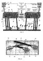
Figure 2 is a graph showing a typical reflective spectrum (by wavelength) of a green leaf; -
Figure 3 is a schematic diagram of an embodiment of a sensing system used for weed detection; -
Figure 4 is a schematic diagram of a source of collimated light; and, -
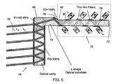
Figure 5 is a schematic diagram of a light source. -
Figure 1 shows a sensing andspraying system 10 which comprises asensing component 12, acontroller 22 and acontrollable spray unit 24. Thesystem 10 is typically attached to a boom of a piece of farm machinery (such as a tractor) and travels over a crop in a field being cultivated. The direction of travel would be right to left of the diagram. The field hasplants 28 of the crop which grow from theground 30 and unwanted plants, hereafter referred to asweeds 26. Thesystem 10 needs to be able to distinguish not only theground 30 from thecrop 28, but in particular needs to distinguish theweeds 26 from thecrop 28. Alternatively the system may be designed to detect other pests such as insects. - The
system 10 operates by producing at least one beam oflight 16 from alight source 14 of thesensing component 12. Thelight beam 16 is directed at objects within a field of view as it moves over the field. The transmittedbeam 16 is reflected off objects, and in this case aweed 26, to produce areflected beam 18. Asensor unit 20 of thesensing component 12 detects thereflected beam 18. Measured reflectance data from thesensor unit 20 is sent to thecontroller 22, which processes the data to identify the object being scanned by thebeam 16. Thecontroller 22 is further arranged to control thespray unit 24 so that at the time thespray unit 24 passes over theweed 26, a valve in thespray unit 24 can be operated so as to spray theweed 26 with a suitable chemical, thereby only using the chemical as required. The identification process undertaken by thecontroller 22 is described below. - In the prior art, the vegetation index is defined as the ratio of reflection at near infrared wavelength (around 800nm) to the reflection at red wavelengths (around 650nm). It has been discovered by the inventor that the use of additional wavelengths provides additional ability to discriminate not only plants from soil but also the ability to discriminate between different types of green plant, for which the prior art vegetation index is not reliable.
- The present invention achieves this by the
light source 14 producing light at three or more different wavelengths. It is desirable to use lasers as the source of light as they are well suited to producing light having very narrow bandwidths. A laser can be regarded as producing light at only the desired wavelength. Each individual laser will produce light at each individual wavelength in an individual beam. In the past complex optics have been used to try to aim light (whether from a laser or not) at a single point having a varying distance from the light source. The inventor has overcome this problem by combining the individual beams into a single combined beam. An example achieves this by use of a collimator described further below. - Referring to
Figure 3 , thesensing component 12 is shown in more detail. Thelight source 14 comprises alaser array 30, a WDM combiner, acollimator 32, which respectively combine and collimate the laser beams from each laser into a single combined, collimatedbeam 48 and abeam splitter 34 which splits the combined, collimatedbeam 48 into a plurality ofparallel beams 16 directed at objects in the field of view. An alternative to use of the beam splitter is to scan thebeam 16 across a path by moving a reflector so as to direct the beam across the path. Thebeam 16 may be pulsed so as to illuminate spots as it traverses the path or it may be continuous. - In one example laser array comprises three AC-driven laser diodes, each producing light at a different wavelength (630nm, 670nm and 780nm). The laser diodes are individually controllable by the
controller 22 via a control circuit. The intensity of the beam emitted by each laser can be controlled by a trim-pot. - The WDM beams are overlapped by the WDM combiner and collimated by the
collimator 32. In one embodiment the combined, collimatedbeam 48 has a diameter of 5mm. - The
beam 16 will usually be pulsed/modulated so that upon demodulation the intensity of the reflectedbeam 18 can distinguished from any background light. - The point of view of
Figure 3 is transverse to the length of travel of the agricultural equipment on which is mounted thesystem 10 ofFigure 1 . - The
beam splitter 34 comprises an elongateoptical cavity 40, formed of a suitable material, such as glass or clear plastics. Theoptical cavity 40 could also be formed of a hollow inside of a prism. Thecavity 40 has a rectangular prism shape with opposite ends 44 and 46, and parallel, oppositelongitudinal sides beam 48 can enter thecavity 40. The inlet 42 is positioned at or near theend 44. A highly reflective coating is applied to the surface of theside 36, which ideally has a reflectance greater than 99%. A partially reflective coating is applied to thesecond side 38, which reflects approximately 90% of light and transmits approximately 10% of light striking it. This enables the majority of thebeam 48 striking the coating to be reflected while allowing some of it to be transmitted. Due to the angle of incidence of the incoming combinedbeam 48 it reflects between the surface coatings ofsides parallel beams 16, which are emitted from theside 38. The reflectivity of the coating on theside 38 in this embodiment is constant, but due to the intensity being progressively degraded by each beam transmitted, the internally reflected beam intensity will progressively decrease as it propagates along the length of thecavity 40. This in turn will produce progressively lessintense beams 16 further away from the inlet 42 towards thesecond end 46. The reflectivity/transmissibility of the coating ofside 38 need not be constant along the length of thecavity 40 and need not be 90%/10%. - An angle of incidence of the combined
beam 48 into the cavity will determined the number of times the beam will be reflected down the length of thecavity 40, which in turn will determine the spacing between eachoutput beam 16. - In one embodiment, the
splitter 34 comprises an optical cavity which is a single glass substrate in the shape of a rectangular prism of dimensions 199mm x 29mm x 14mm, approximately. The ends may be uncoated (clear) so that one can perform as the optical inlet 42. - In this embodiment an angle of incidence of about 19 degrees will produce a beam spacing of about 1cm. A reasonable practical range of angles of incidence is between 1 and 45 degrees and preferably between 10 and 30 degrees, although any angle between (non inclusive) 0 and 90 degrees may be appropriate depending on the application.
- Should it be desired to produce
beams 16 that were not parallel then the shape of one or both of thesides side 36 concave in shape thebeams 16 would diverge, or by making theside 38 concave in shape the beams would converge. - When each
beam 16 strikes an object a dot/spot will be illuminated. On a flat surface thebeams 16 would form a straight line of dots. The reflection of the illumination, from the point of view of thesensor unit 20, will appear as a reflectedbeam 18. - The
sensor unit 20 is placed substantially in line with the spots, although it may be offset. Thesensor unit 20 comprises a one-dimensional imager 50 and animaging lens 52. Thelens 52 focuses each of the points associated with each of the beams onto a sensing element of theimager 50. Thus the elements in the imager are able to produce a one-dimensional image of the reflected beams 18 (i.e. the spots). This one-dimensional image is passed to a precursor signal processor and then onto thecontroller 22. The precursor signal processor may demodulate the signal and/or correlate the timing of a pulse control signal sent to a particular laser source with the received intensity data in order to match the intensity data with a particular wavelength. - In one embodiment,
imager 50 comprises two stacked rows of 1024 pixels, each pixel being 14x14 micrometers in size. - The
lens 52 has an adjustable iris, zoom and focus to properly capture spots produced by theparallel beams 16 striking objects in the field of view. The lens can have its tilt calibrated in X and Y dimensions so complete spot capture is achieved. Theimager 50 is connected to a virtual serial port using a CAT 5 Ethernet cable to a PC (the controller 22) where it is driven using a programmable graphical use interface. Through this interface the sensor's imaging settings can be modified. A series of frames are captured, with each frame including the intensity data. The intensity data of each spot can be measured on a 12-bit intensity scale ranging from 0 to 4096 arbitrary units. - The viewing angle of the
sensor unit 20 to each spot will sequentially increase, which in turn will produce a sequential reduction in the perceived intensity in the reflectedbeam 18. This can be substantially compensated for by the sequential increase in the intensity of the incident beams 16 by placing the sensor unit closest to thelight beam 16 of weakest intensity thereby providing it with a viewing angle closest to 0 degrees. - A complementary sensing system 14' can be positioned on the other side of the
sensor unit 20. Thesensor unit 20 is placed adjacent theend 46 of thesplitter 34 so that it is aligned with the line ofparallel beam 16. Output of thebeams 16 of thesystem 14 and of the beams from the system 14' can be timed so that thesensor unit 20 can be multiplexed with reflectance readings of thesystems 14 and 14'. Indeed the output of each wavelength can be time division multiplexed so that the imager is only reading one wavelength at a time. - Referring to
Figure 4 , thelight source collimator 32 is described in further detail. Thelaser array 30 comprisesfirst laser 60 producing light of wavelength of about 630nm, asecond laser 62 producing light at 670nm, and athird laser 64 producing light at a wavelength of 780nm. Thecollimator 32 comprises afirst reflector 66 and asecond reflector 68.Reflectors reflector 66 light beam fromlaser 62 is transmitted whereas the beam fromlaser 60 is reflected. Thelasers reflector 66 are aligned so that the reflected beam fromlaser 60 is aligned and overlaps (is collimated) with the beam fromlaser 62. Thereflector 68 comprises a thin film which allows light fromlaser 62 to pass therethrough but reflects the combined beam fromlasers laser 64 andreflector 68 are aligned withreflector 66 such that reflected beams fromlasers laser 64 after it is transmitted throughreflector 68. Theresultant beam 48 is collimated from the three different lasers. - A person skilled in the art will realise that this technique can be used to add further lasers (potentially of different wavelengths) with use of additional reflectors with appropriate thin film filters. An example of this is schematically shown as
collimator 32 inFigure 5 and described further below. A person skilled in the art will also realise that the collimator will work with only the first laser, the second laser and the first reflector to collimate the beams from the first and second lasers. - Each
laser beam 48 each laser can be rotated so that thebeam 48 has the same polarisation at each of the wavelengths. For example thefirst laser 60 is rotated so that light does not pass through the polarising filter. Then inturn lasers beam 48 to have the same polarisation, as different polarisation can be a detrimental factor in reading the intensity of the reflectedbeam 18. - Referring to
Figure 5 , an alternative example of thelight source 14 is shown. In this example an L-shaped optical substrate formed of glass comprises theoptical cavity 40 of the splitter 34 (as the base of the L), asection 72 which comprises acollimator section 72, andsection 74, which connects thecollimator section 72 to theoptical cavity 40.Sections collimator section 72 is formed in a similar arrangement to that shown inFigure 4 with a plurality of laser sources each producing a different wavelength λ1, λ2... λN-1, λN of light and a series offilters 80 situated on the outside of thesubstrate section 72 which transmits light from the respective laser but reflects light at other wavelengths (e.g., the filter marked 80 transmits light at λ2, but reflects other wavelengths).Filter 78 transmits light at wavelength λN. The lasers and filters 78 and 80 are arranged with respect to thesection 72 such that theresultant laser beam 48 is collimated. The collimatedbeam 48 strikes areflector 76, which has approximately 100% reflection.Reflector 76 is oriented to send thebeam 48 into the optical cavity 82 at an angle suitable to produce the desired number of combined output parallel beams 16 due to its reflected propagation from side to side down the length of thesplitter 34. - The method of use and operation of the present invention will now be described with reference to the accompanying diagrams.
-
System 10 is mounted for operation such that objects to be identified travel though thebeams 16. In the weed control application thesystem 10 will be mounted on a boom of an agricultural vehicle, which can travel over the crop at a height of about 1 to 2m. Thesystem 10 ofFigure 3 can cover 1 to 3m along the length of the boom and if need beother systems 10 can be placed in parallel on the boom to complete the entire width of the boom. In other applications thesystem 10 may be stationary and the objects being identified will move by, such as on a conveyer belt. - The light beams 16 strike one or more objects producing a series of illuminated spots. The light may be visible or may be outside the visible spectrum. In the weed control application the 630 nm laser light is visible as red. The 670 nm and 780 nm laser light are in the (near) infrared spectrum and are not visible to the human eye. Other wavelengths may be used in other applications. In the weed control application more wavelengths will produce greater accuracy in discrimination, up to about 10 to 15 different wavelengths.
- The reflected
light 18 is captured by thesensor unit 20 and a reading of the intensity of each spot is taken. The readings are provided to thecontroller 22. Thecontroller 22 runs a computer program that normalises the readings, stores the readings and calculates a ratio between each of the normalised intensities. The normalised intensity ratios are compared to a database of intensity ratios to find a match or best match. In the event a match is found an object classification associated with the matching ratios is used to identify the object. - Due to the linear nature of the spots, the location and even a dimension of the identified object can be determined. This may be combined with GPS information on the location of the vehicle for recording and later analysis. Based on the determined location in the line of dots (and thus the location relative to the boom), the distance between the
sensing component 12 andcontrollable spray unit 24, and the speed of travel of the vehicle, operation of thespray unit 24 can be timed to only dispense the chemical on to the object when it is identified as aweed 26. Usually a line ofspray units 24 will be positioned on the boom (or a second trailing boom). By knowing the position of the weed in the line of spots the appropriate spray unit is activated. In the event that the system was configured to detect insects, when an insect is detected it could be sprayed with an insecticide. Likewise in other applications once the object is identified by its ratios of spectral response appropriate action (if any) can be taken. - The database of ratios is constructed by taking sample readings from possible candidate objects. The ratios of intensity of keys wavelengths is recorded in the database along with a classification of the candidate objects for matching against. For example the green leaf in
Figure 2 has a set of ratios of (about) 10.2:10:60. - An alternative to using ratios of intensities is to use the gradient between adjacent wavelength intensity pairs. The ratios can in fact be used to derive the gradients and vice versa. Again an example of gradients of the green leaf in
Figure 2 are (10-10.2) ÷ 40 = - x 0.005 and (60-10) ÷ 110 = 0.455. - Use of the ratios or gradients provides considerably better matching results for identifying objects in the database than the prior method of using a VI because a larger portion of the reflectance spectrum is able to be used in making the match.
- The
collimator 32 can be used in other applications. It operates by receiving light from laser 60 (or some other source of collimated light) and reflecting it off ofreflector 66. At the same time it receives light from laser 62 (or another collimated light source). The light fromlaser 62 is transmitted though thereflector 66 and aligns with the reflected light fromlaser 60. The light fromlaser 60 andlaser 62 is then collimated. This collimated light can then be reflected offreflector 68. At the same time thecollimator 32 receives light from laser 64 (or another collimated light source). The light fromlaser 64 is transmitted though thereflector 68 and aligns with the reflected light fromlaser 60 andlaser 62. The resultingoutput beam 48 is an alignment (collimation) of light fromlasers - The
splitter 40 can be used in other applications. It operates by receivinglight 48 through the optical inlet 42. The light refracts according to the angle of incidence and is partly transmitted through the coating ofside 38 to form afirst beam 16. It is also reflected by the coating ofside 38 and strikes the coating ofside 36 further along the length of the cavity towardsend 46, whereupon it is again reflected to again strike the coating ofside 38. This light is partly transmitted through the coating onside 38 to form a second beam parallel to the first beam. It is also reflected by the coating ofside 38 to again strike the coating ofside 36 further along the length of the cavity towardsend 46. This process continues with the beam bouncing back and forth betweensides end 46 and produces further beams fromside 38 which are parallel to the first and second beams. It is readily apparent that the dimensions of the cavity and the angle of incidence of the input beam will affect the spacing and number of output beams. It is readily apparent that the percentage of transmission/reflectance of the beam through the coating ofside 38 will affect the intensity of the output beams. - It will be understood to persons skilled in the art of the invention that many modifications may be made without departing from the scope of the invention as defined by the appended claims.
Claims (12)
- A sensing system for discriminating plant matter comprising:a light source comprising three or more lasers, each laser being arranged to produce a pulsed laser beam of a different wavelength; a WDM combiner, collimator and time division multiplexer for combining the pulsed laser light beams from the three or more lasers into a combined, collimated and time division multiplexed light beam; a splitter for splitting the combined collimated and time division multiplexed light beam into a plurality of light beams each having the different wavelengths such that the light beams are directed to distinct non-overlapping areas in a field of view;a sensor for distinctly measuring the reflectance from each of the distinct non-overlapping areas at each of the distinct wavelengths; andan identifier for identifying at east one plant type in the field of view from the measured reflectance at each of the wavelengths at each of the distinct non-overlapping area.
- The sensing system as claimed in claim 1, wherein the identifier identifies the at least one plant type by determining a ratio between the measured light reflectances at each of the wavelengths and comparing the determined ratio with a database of reference ratios of known plant matter so as to identify observed plant matter at each of the distinct non-overlapping areas.
- The sensing system as claimed in claim 1, wherein the identifier identifies the at least one plant type by determining gradients between the measured reflectances at each of the wavelengths and comparing the determined gradients with a database of reference gradients of known plant matter so as to identify observed plant matter at each of the distinct non-overlapping areas.
- The sensing system as claimed in any one of the preceding claims, wherein the splitter is configured such that the intensity of each pulsed laser light beam progressively decreases and the sensor is positioned such that a most intense light beam is furthest from the sensor.
- The sensing system as claimed in any one of the preceding claims, wherein the collimator comprises:a first reflector configured to reflect light at a first of the wavelengths and also configured to pass light at a second of the wavelengths, wherein the first reflector, a first one of the lasers and a second one of the lasers are arranged such that a first laser beam from the first laser is reflected by the first reflector so as to be combined and collimated with a second laser beam from the second laser which passes through the first reflector;a second reflector configured to reflect collimated laser beams at the first and second wavelengths and also configured to pass a laser beam at a third of the wavelengths, wherein a third one of the lasers, the first reflector and second reflector are arranged such that the combined laser beams from the first and second lasers are reflected by the second reflector so as to be combined and collimated with a third laser beam from the third laser which passes through the second reflector.
- The sensing system as claimed in any one of the preceding claims, wherein the splitter comprises:an elongate optical cavity having a first end and a second end, a first longitudinal side and a second opposite longitudinal side;a reflective layer on the first longitudinal side that reflects light inside the optical cavity;a partially reflective layer on the second longitudinal side such that part of the combined laser light beam in the optical cavity that strikes the partially reflective layer will be reflected and part will be transmitted out of the optical cavity; andan optical entry to the cavity in or adjacent to the first end such that the combined laser light beam may enter the cavity and be reflected between the longitudinal sides towards the second end, with part of the combined laser beam exiting the cavity through the second longitudinal side such that the combined laser light beam is transformed into a plurality of spaced apart laser light beams emanating from the second longitudinal side so as to illuminate the plurality of distinct non-overlapping areas in the field of view.
- The sensing system as claimed in claim 2, wherein the identifier comprises:a storage for a database of reference characteristics of plant matter of, or derived from, reflected intensity of light striking each candidate plant matter at three or more different specified wavelengths; anda processor for determining the ratio of the measured reflectance at each of the distinct non-overlapping areas and comparing the determined ratio to the reference characteristics in the database to identify the plant type.
- The sensing system as claimed in claim 3, wherein the identifier comprises:storage for a database of reference characteristics of plant matter of, or derived from, reflected intensity of light striking each candidate plant matter at three or more different specified wavelengths; anda processor for determining a gradient of the measured reflectances at each of the distinct non-overlapping areas and comparing the determined gradient to the reference characteristics in the database to identify the plant type.
- The sensing system as claimed in any one of the preceding claims, wherein an orientation of each of the lasers is such that the polarisation of the combined laser light beams from from the combiner is aligned at the three or more wavelengths.
- A method of identification of plant matter comprising:producing three or more pulsed laser light beams each having a different wavelength; WDM combining, collimating and time division multiplexing the three or more pulsed laser light beams into a combined, collimated and time division multiplexed light beam;splitting the combined collimated and time division multiplexed light beam into a plurality of spaced apart beams such that light beams are directed to distinct non-overlapping areas in a field of view;measuring the reflectance at each of the distinct wavelengths and from each of the distinct non-overlapping areas; andidentifying at least one plant type in the field of view from the measured reflectance at each of the distinct non-overlapping areas.
- The method as claimed in claim 10, wherein identification of plant matter comprises:providing a database of reference characteristics of candidate plant matter, each reference characteristic comprising ratios of reflectance intensities from light striking each candidate plant matter at three or more different specified wavelengths;determining a ratio of reflectance light intensities at three or more different specified wavelengths; andcomparing the determined ratios to the reference characteristics to identify the plant matter.
- The method as claimed in claim 10 or claim 11, wherein identification of plant matter comprises:providing a database of reference characteristics of candidate plant matter, each reference characteristic comprising gradients between different reflectance intensities from light striking each candidate plant matter at three or more different specified wavelengths;determining gradients between different reflectance intensities at three or more different specified wavelengths; andcomparing the determined gradients to the reference characteristics to identify the plant matter.
Priority Applications (1)
| Application Number | Priority Date | Filing Date | Title |
|---|---|---|---|
| PL07784717T PL2052236T3 (en) | 2006-08-01 | 2007-08-01 | Optical sensing system and method for discriminating plant matter |
Applications Claiming Priority (2)
| Application Number | Priority Date | Filing Date | Title |
|---|---|---|---|
| AU2006904147A AU2006904147A0 (en) | 2006-08-01 | Optical sensing system and optical devices therefor | |
| PCT/AU2007/001075 WO2008014553A1 (en) | 2006-08-01 | 2007-08-01 | Optical sensing system and optical devices therefor |
Publications (3)
| Publication Number | Publication Date |
|---|---|
| EP2052236A1 EP2052236A1 (en) | 2009-04-29 |
| EP2052236A4 EP2052236A4 (en) | 2009-08-19 |
| EP2052236B1 true EP2052236B1 (en) | 2012-03-28 |
Family
ID=38996782
Family Applications (1)
| Application Number | Title | Priority Date | Filing Date |
|---|---|---|---|
| EP07784717A Active EP2052236B1 (en) | 2006-08-01 | 2007-08-01 | Optical sensing system and method for discriminating plant matter |
Country Status (10)
| Country | Link |
|---|---|
| US (1) | US8179533B2 (en) |
| EP (1) | EP2052236B1 (en) |
| AT (1) | ATE551597T1 (en) |
| AU (1) | AU2007281027B2 (en) |
| CA (1) | CA2659522C (en) |
| DK (1) | DK2052236T3 (en) |
| ES (1) | ES2395062T3 (en) |
| PL (1) | PL2052236T3 (en) |
| WO (1) | WO2008014553A1 (en) |
| ZA (1) | ZA200901433B (en) |
Cited By (1)
| Publication number | Priority date | Publication date | Assignee | Title |
|---|---|---|---|---|
| LV15655A (en) * | 2021-01-13 | 2022-07-20 | Weedbot, Sia | Device for protection from concentrated optical radiation |
Families Citing this family (26)
| Publication number | Priority date | Publication date | Assignee | Title |
|---|---|---|---|---|
| EP2194368B1 (en) * | 2008-12-03 | 2019-07-17 | Grundfos Management A/S | Sensor system for detecting and specifying individual particles in a fluid |
| CA2799649C (en) * | 2010-05-18 | 2018-11-27 | Photonic Detection Systems Pty Ltd | A device for selecting specific matter |
| DE102010034603B4 (en) * | 2010-08-13 | 2013-01-31 | Franke Gmbh | Sensor system and method for determining an optical property of a plant |
| BR112013011007A2 (en) | 2010-11-04 | 2016-08-02 | Dow Agrosciences Llc | method and apparatus for treating target plants |
| US8902413B2 (en) * | 2012-02-21 | 2014-12-02 | Trimble Navigation Limited | Cell phone NDVI sensor |
| WO2014195952A1 (en) * | 2013-06-06 | 2014-12-11 | Flora Fotonica Ltd | A system and method for providing illumination to plants |
| US9565848B2 (en) | 2013-09-13 | 2017-02-14 | Palo Alto Research Center Incorporated | Unwanted plant removal system |
| US9609859B2 (en) | 2013-09-13 | 2017-04-04 | Palo Alto Research Center Incorporated | Unwanted plant removal system having a stabilization system |
| US9609858B2 (en) * | 2013-09-13 | 2017-04-04 | Palo Alto Research Center Incorporated | Unwanted plant removal system having variable optics |
| EP2887053A1 (en) | 2013-12-18 | 2015-06-24 | Basf Se | Determination of a fungal infection of a plant by chlorophyll fluorescence induced by different excitation wavelengths |
| AU2016269849B2 (en) * | 2015-06-05 | 2019-08-15 | Agerris Pty Ltd | Automatic target recognition and management system |
| CN105352893B (en) * | 2015-07-15 | 2018-02-06 | 电子科技大学 | A kind of Chlorophyll inversion method suitable for vegetation sparse area |
| US10178856B2 (en) * | 2015-09-01 | 2019-01-15 | Isca Technologies, Inc. | Systems and methods for classifying flying insects |
| US20170295323A1 (en) * | 2016-04-08 | 2017-10-12 | Empire Technology Development Llc | Sub-surface emr transmission for scanning produce |
| US11266054B2 (en) | 2017-01-24 | 2022-03-08 | Cnh Industrial America Llc | System and method for automatically estimating and adjusting crop residue parameters as a tillage operation is being performed |
| PL3367054T3 (en) * | 2017-02-28 | 2020-09-21 | Phenospex B.V. | Device for optically recording objects |
| CN107543802A (en) * | 2017-08-31 | 2018-01-05 | 维沃移动通信有限公司 | The method for cleaning and system of a kind of harmful organism |
| JP7009126B2 (en) * | 2017-09-07 | 2022-01-25 | 株式会社トプコン | measuring device |
| RU2664757C1 (en) * | 2017-11-29 | 2018-08-22 | федеральное государственное бюджетное образовательное учреждение высшего образования "Московский государственный технический университет имени Н.Э. Баумана (национальный исследовательский университет)" (МГТУ им. Н.Э. Баумана) | Remote method for detecting vegetation, that is in unfavorable conditions for development |
| EP3824282A4 (en) * | 2018-07-17 | 2022-03-23 | Photonic Detection Systems Pty Ltd | A detection system for detecting matter and distinguishing specific matter from other matter |
| EP3824270A4 (en) * | 2018-07-17 | 2022-03-23 | Photonic Detection Systems Pty Ltd | DETECTION SYSTEM FOR DETECTING A MATERIAL AND DISTINGUISHING A SPECIFIC MATERIAL FROM ANOTHER MATERIAL |
| CN109937999B (en) * | 2019-03-21 | 2022-08-12 | 中国科学院合肥物质科学研究院 | A laser device for killing the original plant of drugs |
| RU2763438C2 (en) * | 2019-06-20 | 2021-12-29 | ФГБОУ ВО "Оренбургский государственный аграрный университет" | Stand for setting up contactless sensors |
| CN113841041A (en) * | 2019-06-27 | 2021-12-24 | 株式会社堀场制作所 | Analysis device |
| CN113640254B (en) * | 2021-08-11 | 2023-10-24 | 淮阴师范学院 | Crop growth information sensor capable of maintaining self-balance |
| US12315311B2 (en) | 2022-11-30 | 2025-05-27 | Cnh Industrial America Llc | Systems and methods for monitoring implement performance during an agricultural operation |
Family Cites Families (21)
| Publication number | Priority date | Publication date | Assignee | Title |
|---|---|---|---|---|
| US3910701A (en) * | 1973-07-30 | 1975-10-07 | George R Henderson | Method and apparatus for measuring light reflectance absorption and or transmission |
| US4035070A (en) | 1975-12-18 | 1977-07-12 | Xerox Corporation | Apparatus and method for optical generation of a structured charge-discharge pattern on a photoreceptor |
| JPS63304222A (en) * | 1987-06-04 | 1988-12-12 | Minolta Camera Co Ltd | Laser light source device |
| US5132538A (en) * | 1991-05-24 | 1992-07-21 | Nirsystems Incorporated | Measuring percentage of protein in whole grain samples |
| US5585626A (en) | 1992-07-28 | 1996-12-17 | Patchen, Inc. | Apparatus and method for determining a distance to an object in a field for the controlled release of chemicals on plants, weeds, trees or soil and/or guidance of farm vehicles |
| US5296702A (en) * | 1992-07-28 | 1994-03-22 | Patchen California | Structure and method for differentiating one object from another object |
| US5793035A (en) * | 1992-07-28 | 1998-08-11 | Patchen, Inc. | Apparatus and method for spraying herbicide on weeds in a cotton field |
| FR2703932B1 (en) * | 1993-04-16 | 1995-07-07 | Materiel Arboriculture | METHOD AND DEVICE FOR AUTOMATIC SORTING OF PRODUCTS, ESPECIALLY FRUITS AND VEGETABLES. |
| FR2708998B1 (en) | 1993-08-13 | 1996-06-14 | Bp France Sa | Spectrophotometric apparatus with multiplex device and method using the apparatus. |
| US5507115A (en) * | 1994-02-04 | 1996-04-16 | Canadian Space Agency | Selective applications of weed control chemicals |
| US5480354A (en) * | 1994-11-03 | 1996-01-02 | Loral Corporation | Smart crop yield monitor |
| US5900634A (en) | 1994-11-14 | 1999-05-04 | Soloman; Sabrie | Real-time on-line analysis of organic and non-organic compounds for food, fertilizers, and pharmaceutical products |
| FR2732626B1 (en) * | 1995-04-06 | 1997-07-04 | Materiel Arboriculture | ANALYSIS DEVICE FOR AUTOMATIC SORTING OF PRODUCTS, ESPECIALLY FRUITS AND VEGETABLES |
| US5789741A (en) | 1996-10-31 | 1998-08-04 | Patchen, Inc. | Detecting plants in a field by detecting a change in slope in a reflectance characteristic |
| US6160902A (en) * | 1997-10-10 | 2000-12-12 | Case Corporation | Method for monitoring nitrogen status using a multi-spectral imaging system |
| US6563976B1 (en) | 2000-05-09 | 2003-05-13 | Blaze Network Products, Inc. | Cost-effective wavelength division multiplexer and demultiplexer |
| AUPR457401A0 (en) | 2001-04-26 | 2001-05-24 | Weed Control Australia Pty Ltd | Selective weed discrimination |
| US6596996B1 (en) * | 2001-07-24 | 2003-07-22 | The Board Of Regents For Oklahoma State University | Optical spectral reflectance sensor and controller |
| US7106446B2 (en) | 2002-06-21 | 2006-09-12 | Therma-Wave, Inc. | Modulated reflectance measurement system with multiple wavelengths |
| US7408145B2 (en) * | 2003-09-23 | 2008-08-05 | Kyle Holland | Light sensing instrument with modulated polychromatic source |
| US7417744B2 (en) * | 2006-02-27 | 2008-08-26 | Los Alamos National Security, Llc | Coherent hybrid electromagnetic field imaging |
-
2007
- 2007-08-01 AU AU2007281027A patent/AU2007281027B2/en not_active Ceased
- 2007-08-01 ZA ZA200901433A patent/ZA200901433B/en unknown
- 2007-08-01 ES ES07784717T patent/ES2395062T3/en active Active
- 2007-08-01 AT AT07784717T patent/ATE551597T1/en active
- 2007-08-01 DK DK07784717.6T patent/DK2052236T3/en active
- 2007-08-01 WO PCT/AU2007/001075 patent/WO2008014553A1/en not_active Ceased
- 2007-08-01 PL PL07784717T patent/PL2052236T3/en unknown
- 2007-08-01 US US12/375,933 patent/US8179533B2/en active Active
- 2007-08-01 CA CA2659522A patent/CA2659522C/en active Active
- 2007-08-01 EP EP07784717A patent/EP2052236B1/en active Active
Cited By (1)
| Publication number | Priority date | Publication date | Assignee | Title |
|---|---|---|---|---|
| LV15655A (en) * | 2021-01-13 | 2022-07-20 | Weedbot, Sia | Device for protection from concentrated optical radiation |
Also Published As
| Publication number | Publication date |
|---|---|
| ES2395062T3 (en) | 2013-02-07 |
| CA2659522C (en) | 2017-08-29 |
| PL2052236T3 (en) | 2012-10-31 |
| US8179533B2 (en) | 2012-05-15 |
| AU2007281027B2 (en) | 2013-02-07 |
| AU2007281027A1 (en) | 2008-02-07 |
| US20100014096A1 (en) | 2010-01-21 |
| WO2008014553A1 (en) | 2008-02-07 |
| ATE551597T1 (en) | 2012-04-15 |
| EP2052236A4 (en) | 2009-08-19 |
| ZA200901433B (en) | 2010-05-26 |
| CA2659522A1 (en) | 2008-02-07 |
| DK2052236T3 (en) | 2012-07-16 |
| EP2052236A1 (en) | 2009-04-29 |
Similar Documents
| Publication | Publication Date | Title |
|---|---|---|
| EP2052236B1 (en) | Optical sensing system and method for discriminating plant matter | |
| US9565848B2 (en) | Unwanted plant removal system | |
| US7099004B2 (en) | Digital spectral identifier-controller and related methods | |
| CA2445802C (en) | Selective weed discrimination | |
| US9609859B2 (en) | Unwanted plant removal system having a stabilization system | |
| CA2454827C (en) | Optical spectral reflectance sensor and controller | |
| US9609858B2 (en) | Unwanted plant removal system having variable optics | |
| US6443365B1 (en) | Discriminating ground vegetation in agriculture | |
| CA2688260A1 (en) | In-situ plant analysis apparatus, method for tracking the state or evolution of a culture and method for managing vegetable processing | |
| Symonds et al. | A real-time plant discrimination system utilising discrete reflectance spectroscopy | |
| Askraba et al. | Laser-stabilized real-time plant discrimination sensor for precision agriculture | |
| US20250199125A1 (en) | Remote sensing device with duplex optical element and related methods | |
| AU2011256115B2 (en) | A device for selecting specific matter | |
| Hilton | Laser-induced fluorescence for discrimination of crops and weeds | |
| Askraba et al. | Design of laser multi-beam generator for plant discrimination | |
| AU2002249005B2 (en) | Selective plant discrimination | |
| RO138315A0 (en) | Early identification of grape wine leaf integrity by using spectral sensors | |
| Sahba et al. | Photonics-based Spectral Reflectance Sensor for Plant Discrimination | |
| Paap et al. | Evaluation of an optical image sensor for use in the micro-photonic real-time vegetation discrimination system |
Legal Events
| Date | Code | Title | Description |
|---|---|---|---|
| PUAI | Public reference made under article 153(3) epc to a published international application that has entered the european phase |
Free format text: ORIGINAL CODE: 0009012 |
|
| 17P | Request for examination filed |
Effective date: 20090227 |
|
| AK | Designated contracting states |
Kind code of ref document: A1 Designated state(s): AT BE BG CH CY CZ DE DK EE ES FI FR GB GR HU IE IS IT LI LT LU LV MC MT NL PL PT RO SE SI SK TR |
|
| AX | Request for extension of the european patent |
Extension state: AL BA HR MK RS |
|
| A4 | Supplementary search report drawn up and despatched |
Effective date: 20090717 |
|
| RIC1 | Information provided on ipc code assigned before grant |
Ipc: A01M 7/00 20060101ALI20090713BHEP Ipc: B07C 5/342 20060101ALI20090713BHEP Ipc: G01N 21/39 20060101ALI20090713BHEP Ipc: G01N 21/25 20060101ALI20090713BHEP Ipc: A01M 21/04 20060101ALI20090713BHEP Ipc: G01N 21/35 20060101ALI20090713BHEP Ipc: G01N 21/55 20060101AFI20080328BHEP |
|
| 17Q | First examination report despatched |
Effective date: 20090929 |
|
| GRAP | Despatch of communication of intention to grant a patent |
Free format text: ORIGINAL CODE: EPIDOSNIGR1 |
|
| RIC1 | Information provided on ipc code assigned before grant |
Ipc: A01M 21/00 20060101ALI20110831BHEP Ipc: A01M 7/00 20060101ALI20110831BHEP Ipc: G01N 21/35 20060101ALI20110831BHEP Ipc: G01N 21/55 20060101AFI20110831BHEP Ipc: G01N 21/25 20060101ALI20110831BHEP Ipc: B07C 5/342 20060101ALI20110831BHEP Ipc: A01M 21/04 20060101ALI20110831BHEP Ipc: G01N 21/39 20060101ALI20110831BHEP |
|
| RTI1 | Title (correction) |
Free format text: OPTICAL SENSING SYSTEM AND METHOD FOR DISCRIMINATING PLANT MATTER |
|
| DAX | Request for extension of the european patent (deleted) | ||
| GRAS | Grant fee paid |
Free format text: ORIGINAL CODE: EPIDOSNIGR3 |
|
| GRAA | (expected) grant |
Free format text: ORIGINAL CODE: 0009210 |
|
| AK | Designated contracting states |
Kind code of ref document: B1 Designated state(s): AT BE BG CH CY CZ DE DK EE ES FI FR GB GR HU IE IS IT LI LT LU LV MC MT NL PL PT RO SE SI SK TR |
|
| REG | Reference to a national code |
Ref country code: GB Ref legal event code: FG4D |
|
| REG | Reference to a national code |
Ref country code: CH Ref legal event code: EP |
|
| REG | Reference to a national code |
Ref country code: AT Ref legal event code: REF Ref document number: 551597 Country of ref document: AT Kind code of ref document: T Effective date: 20120415 |
|
| REG | Reference to a national code |
Ref country code: IE Ref legal event code: FG4D |
|
| REG | Reference to a national code |
Ref country code: DE Ref legal event code: R096 Ref document number: 602007021640 Country of ref document: DE Effective date: 20120524 |
|
| REG | Reference to a national code |
Ref country code: RO Ref legal event code: EPE |
|
| REG | Reference to a national code |
Ref country code: DK Ref legal event code: T3 |
|
| REG | Reference to a national code |
Ref country code: SE Ref legal event code: TRGR |
|
| REG | Reference to a national code |
Ref country code: NL Ref legal event code: VDEP Effective date: 20120328 |
|
| PG25 | Lapsed in a contracting state [announced via postgrant information from national office to epo] |
Ref country code: LT Free format text: LAPSE BECAUSE OF FAILURE TO SUBMIT A TRANSLATION OF THE DESCRIPTION OR TO PAY THE FEE WITHIN THE PRESCRIBED TIME-LIMIT Effective date: 20120328 |
|
| LTIE | Lt: invalidation of european patent or patent extension |
Effective date: 20120328 |
|
| PG25 | Lapsed in a contracting state [announced via postgrant information from national office to epo] |
Ref country code: FI Free format text: LAPSE BECAUSE OF FAILURE TO SUBMIT A TRANSLATION OF THE DESCRIPTION OR TO PAY THE FEE WITHIN THE PRESCRIBED TIME-LIMIT Effective date: 20120328 Ref country code: LV Free format text: LAPSE BECAUSE OF FAILURE TO SUBMIT A TRANSLATION OF THE DESCRIPTION OR TO PAY THE FEE WITHIN THE PRESCRIBED TIME-LIMIT Effective date: 20120328 Ref country code: GR Free format text: LAPSE BECAUSE OF FAILURE TO SUBMIT A TRANSLATION OF THE DESCRIPTION OR TO PAY THE FEE WITHIN THE PRESCRIBED TIME-LIMIT Effective date: 20120629 |
|
| REG | Reference to a national code |
Ref country code: AT Ref legal event code: MK05 Ref document number: 551597 Country of ref document: AT Kind code of ref document: T Effective date: 20120328 |
|
| PG25 | Lapsed in a contracting state [announced via postgrant information from national office to epo] |
Ref country code: CY Free format text: LAPSE BECAUSE OF FAILURE TO SUBMIT A TRANSLATION OF THE DESCRIPTION OR TO PAY THE FEE WITHIN THE PRESCRIBED TIME-LIMIT Effective date: 20120328 |
|
| PG25 | Lapsed in a contracting state [announced via postgrant information from national office to epo] |
Ref country code: IS Free format text: LAPSE BECAUSE OF FAILURE TO SUBMIT A TRANSLATION OF THE DESCRIPTION OR TO PAY THE FEE WITHIN THE PRESCRIBED TIME-LIMIT Effective date: 20120728 Ref country code: SI Free format text: LAPSE BECAUSE OF FAILURE TO SUBMIT A TRANSLATION OF THE DESCRIPTION OR TO PAY THE FEE WITHIN THE PRESCRIBED TIME-LIMIT Effective date: 20120328 Ref country code: CZ Free format text: LAPSE BECAUSE OF FAILURE TO SUBMIT A TRANSLATION OF THE DESCRIPTION OR TO PAY THE FEE WITHIN THE PRESCRIBED TIME-LIMIT Effective date: 20120328 Ref country code: BE Free format text: LAPSE BECAUSE OF FAILURE TO SUBMIT A TRANSLATION OF THE DESCRIPTION OR TO PAY THE FEE WITHIN THE PRESCRIBED TIME-LIMIT Effective date: 20120328 Ref country code: EE Free format text: LAPSE BECAUSE OF FAILURE TO SUBMIT A TRANSLATION OF THE DESCRIPTION OR TO PAY THE FEE WITHIN THE PRESCRIBED TIME-LIMIT Effective date: 20120328 |
|
| REG | Reference to a national code |
Ref country code: PL Ref legal event code: T3 |
|
| PG25 | Lapsed in a contracting state [announced via postgrant information from national office to epo] |
Ref country code: PT Free format text: LAPSE BECAUSE OF FAILURE TO SUBMIT A TRANSLATION OF THE DESCRIPTION OR TO PAY THE FEE WITHIN THE PRESCRIBED TIME-LIMIT Effective date: 20120730 Ref country code: SK Free format text: LAPSE BECAUSE OF FAILURE TO SUBMIT A TRANSLATION OF THE DESCRIPTION OR TO PAY THE FEE WITHIN THE PRESCRIBED TIME-LIMIT Effective date: 20120328 |
|
| PG25 | Lapsed in a contracting state [announced via postgrant information from national office to epo] |
Ref country code: AT Free format text: LAPSE BECAUSE OF FAILURE TO SUBMIT A TRANSLATION OF THE DESCRIPTION OR TO PAY THE FEE WITHIN THE PRESCRIBED TIME-LIMIT Effective date: 20120328 Ref country code: NL Free format text: LAPSE BECAUSE OF FAILURE TO SUBMIT A TRANSLATION OF THE DESCRIPTION OR TO PAY THE FEE WITHIN THE PRESCRIBED TIME-LIMIT Effective date: 20120328 |
|
| PLBE | No opposition filed within time limit |
Free format text: ORIGINAL CODE: 0009261 |
|
| STAA | Information on the status of an ep patent application or granted ep patent |
Free format text: STATUS: NO OPPOSITION FILED WITHIN TIME LIMIT |
|
| REG | Reference to a national code |
Ref country code: ES Ref legal event code: FG2A Ref document number: 2395062 Country of ref document: ES Kind code of ref document: T3 Effective date: 20130207 |
|
| 26N | No opposition filed |
Effective date: 20130103 |
|
| REG | Reference to a national code |
Ref country code: CH Ref legal event code: PL |
|
| PG25 | Lapsed in a contracting state [announced via postgrant information from national office to epo] |
Ref country code: MC Free format text: LAPSE BECAUSE OF NON-PAYMENT OF DUE FEES Effective date: 20120831 |
|
| REG | Reference to a national code |
Ref country code: DE Ref legal event code: R097 Ref document number: 602007021640 Country of ref document: DE Effective date: 20130103 |
|
| PG25 | Lapsed in a contracting state [announced via postgrant information from national office to epo] |
Ref country code: CH Free format text: LAPSE BECAUSE OF NON-PAYMENT OF DUE FEES Effective date: 20120831 Ref country code: LI Free format text: LAPSE BECAUSE OF NON-PAYMENT OF DUE FEES Effective date: 20120831 |
|
| REG | Reference to a national code |
Ref country code: IE Ref legal event code: MM4A |
|
| PG25 | Lapsed in a contracting state [announced via postgrant information from national office to epo] |
Ref country code: BG Free format text: LAPSE BECAUSE OF FAILURE TO SUBMIT A TRANSLATION OF THE DESCRIPTION OR TO PAY THE FEE WITHIN THE PRESCRIBED TIME-LIMIT Effective date: 20120628 Ref country code: IE Free format text: LAPSE BECAUSE OF NON-PAYMENT OF DUE FEES Effective date: 20120801 |
|
| PG25 | Lapsed in a contracting state [announced via postgrant information from national office to epo] |
Ref country code: MT Free format text: LAPSE BECAUSE OF FAILURE TO SUBMIT A TRANSLATION OF THE DESCRIPTION OR TO PAY THE FEE WITHIN THE PRESCRIBED TIME-LIMIT Effective date: 20120328 |
|
| PG25 | Lapsed in a contracting state [announced via postgrant information from national office to epo] |
Ref country code: TR Free format text: LAPSE BECAUSE OF FAILURE TO SUBMIT A TRANSLATION OF THE DESCRIPTION OR TO PAY THE FEE WITHIN THE PRESCRIBED TIME-LIMIT Effective date: 20120328 |
|
| PG25 | Lapsed in a contracting state [announced via postgrant information from national office to epo] |
Ref country code: LU Free format text: LAPSE BECAUSE OF NON-PAYMENT OF DUE FEES Effective date: 20120801 |
|
| PG25 | Lapsed in a contracting state [announced via postgrant information from national office to epo] |
Ref country code: HU Free format text: LAPSE BECAUSE OF FAILURE TO SUBMIT A TRANSLATION OF THE DESCRIPTION OR TO PAY THE FEE WITHIN THE PRESCRIBED TIME-LIMIT Effective date: 20070801 |
|
| REG | Reference to a national code |
Ref country code: FR Ref legal event code: PLFP Year of fee payment: 10 |
|
| REG | Reference to a national code |
Ref country code: FR Ref legal event code: PLFP Year of fee payment: 11 |
|
| REG | Reference to a national code |
Ref country code: DE Ref legal event code: R082 Ref document number: 602007021640 Country of ref document: DE Representative=s name: FLACH BAUER & PARTNER PATENTANWAELTE MBB, DE Ref country code: DE Ref legal event code: R082 Ref document number: 602007021640 Country of ref document: DE Representative=s name: FLACH BAUER STAHL PATENTANWAELTE PARTNERSCHAFT, DE |
|
| REG | Reference to a national code |
Ref country code: FR Ref legal event code: PLFP Year of fee payment: 12 |
|
| P01 | Opt-out of the competence of the unified patent court (upc) registered |
Effective date: 20230626 |
|
| PGFP | Annual fee paid to national office [announced via postgrant information from national office to epo] |
Ref country code: DE Payment date: 20240821 Year of fee payment: 18 |
|
| PGFP | Annual fee paid to national office [announced via postgrant information from national office to epo] |
Ref country code: DK Payment date: 20240829 Year of fee payment: 18 |
|
| PGFP | Annual fee paid to national office [announced via postgrant information from national office to epo] |
Ref country code: GB Payment date: 20240823 Year of fee payment: 18 |
|
| PGFP | Annual fee paid to national office [announced via postgrant information from national office to epo] |
Ref country code: FR Payment date: 20240828 Year of fee payment: 18 |
|
| PGFP | Annual fee paid to national office [announced via postgrant information from national office to epo] |
Ref country code: ES Payment date: 20240927 Year of fee payment: 18 |
|
| PGFP | Annual fee paid to national office [announced via postgrant information from national office to epo] |
Ref country code: PL Payment date: 20240718 Year of fee payment: 18 |
|
| PGFP | Annual fee paid to national office [announced via postgrant information from national office to epo] |
Ref country code: RO Payment date: 20240724 Year of fee payment: 18 Ref country code: IT Payment date: 20240827 Year of fee payment: 18 Ref country code: SE Payment date: 20240821 Year of fee payment: 18 |