EP2052216B1 - Capteur angulaire optoélectronique et procédé destiné à la détermination d'un angle de rotation autour d'un axe - Google Patents
Capteur angulaire optoélectronique et procédé destiné à la détermination d'un angle de rotation autour d'un axe Download PDFInfo
- Publication number
- EP2052216B1 EP2052216B1 EP07786689.5A EP07786689A EP2052216B1 EP 2052216 B1 EP2052216 B1 EP 2052216B1 EP 07786689 A EP07786689 A EP 07786689A EP 2052216 B1 EP2052216 B1 EP 2052216B1
- Authority
- EP
- European Patent Office
- Prior art keywords
- coding
- image
- detector
- code
- angle sensor
- Prior art date
- Legal status (The legal status is an assumption and is not a legal conclusion. Google has not performed a legal analysis and makes no representation as to the accuracy of the status listed.)
- Active
Links
Images

Classifications
-
- G—PHYSICS
- G01—MEASURING; TESTING
- G01D—MEASURING NOT SPECIALLY ADAPTED FOR A SPECIFIC VARIABLE; ARRANGEMENTS FOR MEASURING TWO OR MORE VARIABLES NOT COVERED IN A SINGLE OTHER SUBCLASS; TARIFF METERING APPARATUS; MEASURING OR TESTING NOT OTHERWISE PROVIDED FOR
- G01D5/00—Mechanical means for transferring the output of a sensing member; Means for converting the output of a sensing member to another variable where the form or nature of the sensing member does not constrain the means for converting; Transducers not specially adapted for a specific variable
- G01D5/26—Mechanical means for transferring the output of a sensing member; Means for converting the output of a sensing member to another variable where the form or nature of the sensing member does not constrain the means for converting; Transducers not specially adapted for a specific variable characterised by optical transfer means, i.e. using infrared, visible, or ultraviolet light
- G01D5/32—Mechanical means for transferring the output of a sensing member; Means for converting the output of a sensing member to another variable where the form or nature of the sensing member does not constrain the means for converting; Transducers not specially adapted for a specific variable characterised by optical transfer means, i.e. using infrared, visible, or ultraviolet light with attenuation or whole or partial obturation of beams of light
- G01D5/34—Mechanical means for transferring the output of a sensing member; Means for converting the output of a sensing member to another variable where the form or nature of the sensing member does not constrain the means for converting; Transducers not specially adapted for a specific variable characterised by optical transfer means, i.e. using infrared, visible, or ultraviolet light with attenuation or whole or partial obturation of beams of light the beams of light being detected by photocells
- G01D5/347—Mechanical means for transferring the output of a sensing member; Means for converting the output of a sensing member to another variable where the form or nature of the sensing member does not constrain the means for converting; Transducers not specially adapted for a specific variable characterised by optical transfer means, i.e. using infrared, visible, or ultraviolet light with attenuation or whole or partial obturation of beams of light the beams of light being detected by photocells using displacement encoding scales
- G01D5/34776—Absolute encoders with analogue or digital scales
-
- G—PHYSICS
- G01—MEASURING; TESTING
- G01D—MEASURING NOT SPECIALLY ADAPTED FOR A SPECIFIC VARIABLE; ARRANGEMENTS FOR MEASURING TWO OR MORE VARIABLES NOT COVERED IN A SINGLE OTHER SUBCLASS; TARIFF METERING APPARATUS; MEASURING OR TESTING NOT OTHERWISE PROVIDED FOR
- G01D5/00—Mechanical means for transferring the output of a sensing member; Means for converting the output of a sensing member to another variable where the form or nature of the sensing member does not constrain the means for converting; Transducers not specially adapted for a specific variable
- G01D5/26—Mechanical means for transferring the output of a sensing member; Means for converting the output of a sensing member to another variable where the form or nature of the sensing member does not constrain the means for converting; Transducers not specially adapted for a specific variable characterised by optical transfer means, i.e. using infrared, visible, or ultraviolet light
- G01D5/32—Mechanical means for transferring the output of a sensing member; Means for converting the output of a sensing member to another variable where the form or nature of the sensing member does not constrain the means for converting; Transducers not specially adapted for a specific variable characterised by optical transfer means, i.e. using infrared, visible, or ultraviolet light with attenuation or whole or partial obturation of beams of light
- G01D5/34—Mechanical means for transferring the output of a sensing member; Means for converting the output of a sensing member to another variable where the form or nature of the sensing member does not constrain the means for converting; Transducers not specially adapted for a specific variable characterised by optical transfer means, i.e. using infrared, visible, or ultraviolet light with attenuation or whole or partial obturation of beams of light the beams of light being detected by photocells
- G01D5/347—Mechanical means for transferring the output of a sensing member; Means for converting the output of a sensing member to another variable where the form or nature of the sensing member does not constrain the means for converting; Transducers not specially adapted for a specific variable characterised by optical transfer means, i.e. using infrared, visible, or ultraviolet light with attenuation or whole or partial obturation of beams of light the beams of light being detected by photocells using displacement encoding scales
- G01D5/3473—Circular or rotary encoders
Definitions
- the invention relates to an optoelectronic angle sensor according to the preamble of claim 1 and to a method for determining a rotation angle about an axis according to claim 10.
- optoelectronic angle sensors for determining a rotation angle about an axis comprise a code carrier and an optical detector, which are rotatable relative to each other.
- the optical detector is, for example, a photodetector, a CCD line array or a CCD area array.
- the code carrier is generally designed as a circular disk or as a circular ring and carries along its circumference an optically detectable position code, of which a section is imaged onto the detector.
- the detector is generally much smaller than the code carrier. To miniaturize the angle sensor therefore a reduction of the code carrier is required in the first place. With a code carrier with a reduced diameter, the ratio of detector area to code carrier area can be increased and thus a larger area of the code applied to the code carrier can be detected. In addition, for an angle sensor with the code carrier as a rotating component and the detector as a fixed component, a higher operating stability can be achieved because of the on the Reduce code carrier acting centrifugal forces. In general, the code carrier of the angle sensor rotates. However, it is also possible to fix the code carrier and make the detector rotating.
- the coding can not be arbitrarily refined insofar as ever finer structures ever greater diffraction effects occur and the structures can not be resolved with the required accuracy.
- the angular resolution is determined by the resolution of the coding by means of the detector and thus depends on the resolving power of the detector. However, this is limited because a reduction of the pixel size is limited by the signal-to-noise ratio. Alternatively, a higher angular resolution can be achieved by increasing the diameter of the code carrier, which is in contradiction to all Miniaturmaschinesbestrebache.
- angle sensor designs are downsized by reducing optical or mechanical components.
- the DE 197 50 474 A1 describes a reduction of the diameter of a partial disk of an angle sensor by the dividing disk in the axis of the rotating shaft directly is used.
- the diameter of the dividing disc around an outer enclosure, such as a metal ring, the same can be reduced.
- this mechanical solution allows only the reduction of the part of disc around the outer enclosure and therefore offers only scope for a reduction of the angle sensor in the range of a few percent. It does not provide any possibility to substantially reduce the diameter of the code-bearing surface of the sensor, for example by 80%, and thus to miniaturize the angle sensor.
- the document DE 3924360 discloses a rotation angle sensor according to the prior art.
- Another object of the invention is to provide an opto-electronic angle sensor improved in terms of accuracy of angle determination.
- a further object is to provide a method for determining a rotation angle, which enables the rotation angle determination with a code carrier with a reduced diameter.
- Another object is to provide a method for determining a rotation angle with improved accuracy.
- the invention is based on the fact that the coding of the circular disk of an optoelectronic angle sensor according to the invention is largely completely captured as an image and the captured images-or the detector measurement signals-are interpreted as realizations of a statistical parameter.
- the parameter value characterizing the measurement signals is determined from a constructed distribution of parameter values.
- a substantially complete, in particular overall, evaluatable image of the coding of the circular disk is generated on the detector of the angle sensor.
- 90% of the encoding is captured as an image.
- the image includes information about the relative position of the circular disc and the detector, which are movable relative to each other.
- the relative movement comprises at least one relative rotational movement about an axis.
- the circular disk and the detector can also detect extremely small translatory relative movements and / or tumbling movements, which are e.g. resulting from assembly and / or manufacturing inaccuracies, perform.
- the coding of the circular disc of an inventive angle sensor is designed such that substantially the entire surface of the disc is used. This is realized by providing the largely entire area of the disc with code.
- the code applied to the circular disk has a code which extends in both an azimuthal and a radial direction and changes in an angle-dependent manner in both directions.
- a common code which is applied on a conventional circular disc in the outer region of the circular disc along the circumference and changes angularly in the circumferential direction, both circumferentially and transversely applied to the circular disc of the inventive angle sensor, for example, meandering - the code is so to speak "folded" on the disc.
- the code carries in addition to the usual code in addition also in the radial direction angle-dependent code information.
- the information content of the coding is determined by the number of transitions - also called "nervousness" of the code.
- the transitions are created by changing the characteristics of the code elements, such as light transmission / opacity or reflection / absorption. Due to the largely full-surface application of the coding and thus utilization of substantially the entire surface of the circular disk, a maximized number of transitions is obtained.
- the thus coded disc corresponds to a so-called "coded axis".
- a large number of transitions to the exactly exact angle determination can also be applied to a circular disc reduced in diameter.
- the diameter of the circular disk can be significantly reduced, for example, by more than 90% compared to conventional glass or plastic circular disks with a diameter of about 78 mm used in theodolites.
- the circular disc as "mini disc” with a diameter between 6 mm and 10 mm executable. Such a reduction of the circular disc allows a large reduction in the dimensions of the angle sensor as a whole and thus the realization of a miniaturized angle sensor.
- an angle sensor for angle determination with improved accuracy can be realized with a corresponding design of the circular disk.
- the coding of the circular disk comprises a plurality of partial codes.
- the previously mentioned, azimuthally and radially expanded code can form, for example, a subcode.
- a partial code can be provided as an absolute code applied along the circumference, for example in the outer region of the circular disc, the detection of which provides a coarse value of the angle of rotation which makes it possible to improve the rotational angle determination with respect to the speed of the evaluation algorithm.
- a further subcode can be embodied as an additional code for detecting translational movements of the circular disk, for example as an azimuthally extended radial code, such as in the form of concentric circles around the center of the circular disk, ie in the inner region thereof.
- an azimuthally extended radial code such as in the form of concentric circles around the center of the circular disk, ie in the inner region thereof.
- means are provided for mapping or projecting the coding onto the detector of the angle sensor.
- the device, the circular disk and the detector of the inventive angle sensor are designed and arranged such that the coding is largely completely, in particular total, imaged on the detector.
- an image or measurement pattern is created which has at least 50%, in particular more than 75% and advantageously 100% of the coding.
- the largely complete detection with sufficient resolution of the coding can be realized on the basis of a corresponding lighting concept, a reduced circular disk, the design and arrangement of equipment, disk and detector or by a combination of the above.
- the device For generating the image, the device comprises a radiation source, such as one or more photodiodes for Illuminate the circular disk.
- a radiation source such as one or more photodiodes for Illuminate the circular disk.
- the image is generated in transmitted or reflected light.
- the detector receives the transmitted radiation modulated by the code elements, in reflected-light mode the reflected radiation modulated by the code elements.
- a possible homogeneous illumination of the circular disk or a circular disk area can be realized by beam expansion by means of a corresponding optical system, which may be formed for example by a deflecting mirror or a scattering medium.
- the device is designed in particular for projecting a region of the circular disc which corresponds to the region of the detector elements.
- the device may also include a self-luminous code, e.g. with organic light emitting diodes, represent.
- the circular disk can - as mentioned above - be advantageously reduced in size.
- This enables an economic embodiment of an angle sensor according to the invention with a detector whose area substantially corresponds to the area of the circular disk.
- a detector can be used whose length and width dimensions correspond to the diameter of the circular disk.
- Such an embodiment, in which the code-carrying disc and the detector are dimensioned substantially equal, allows the detection of the substantially entire circular disc surface respectively the applied thereon coding on the detector in a simple manner. additionally can thus advantageously a spacing of the circular disk center of the axis of rotation - an eccentricity can be determined.
- the circular disk and the detector are arranged largely congruent and coaxially centered.
- the detector provides a, e.g. A planar photosensitive detector formed by arrangements of CCD line arrays and CCD column arrays.
- a matrix-like arrangement of photosensitive areas can be realized with a CCD area sensor or CMOS area sensor.
- alternative conventional sensors can be used.
- the image or the measurement signals of the detector contain information about the relative position of the circular disc and the detector, which information is evaluated by comparison with an electronic reference pattern using a parameter-varying comparison method. On the basis of this evaluation even very small and fine code structures can be resolved with high accuracy and the rotation angle can be determined exactly.
- the electronic reference pattern is provided by means of a memory and evaluation component of the inventive angle sensor.
- the memory and evaluation component is further designed for evaluating the detector measurement signals on the basis of the aforementioned evaluation method.
- the storage and evaluation component has a computer program product which contains program code which is adapted to execute the method as it runs on the component.
- the memory and evaluation component is designed for example as a microprocessor.
- An FPGA (Field Programmable Gate Array) or an ASIC (Application Specific Integrated Circuit) is also suitable as a memory and evaluation component.
- the reference pattern can be modeled as a statistical distribution for an unknown characteristic quantity of the angle determination or the detector measurement signals.
- the reference pattern represents an estimation function of the size.
- the characteristic variable may be the angle of rotation.
- the unknown size of the statistical model can be determined using statistical methods, such as estimation methods.
- the reference pattern can also be formed by an algorithm which simulates or duplicates the measurement pattern or the image respectively the detector measurement signals and / or the coding. For example, for a most realistic description of the measurement pattern, the code structure, the imaging parameters of the device and the detector, and aberrations are taken into account.
- the parameter represents, for example, a reference rotation angle which describes the rotation angle or the relative rotational position of the circular disk and the detector.
- the parameter estimate yields the value for the reference rotation angle which would most likely produce the measurement pattern.
- the measurement pattern is evaluated on the basis of a mathematical correlation method based on an integral comparison of the measurement pattern with the parameterized electronic reference pattern.
- the parameter represents a correlation factor which is a measure of the match of measurement and reference patterns.
- the parameter is varied until a predetermined correlation condition - e.g. a maximum or minimum correlation value - is reached.
- the reference pattern is provided - for example in terms of model theory - as a stationary grating provided with a frequency slightly different from the frequency of a high-frequency grating, so that a digital superimposition of the grids leads to the known moiré structures.
- the position information of the measuring pattern is evaluated on the basis of an integral comparison of the measuring pattern with the reference pattern.
- lattice structures are, for example Radial grating structures, such as a Siemens star, or structures such as radial Fresnelzonengitter - radial "chirp" - suitable.
- the method according to the invention can additionally use further position information.
- a coarse absolute value for the angle of rotation can be determined from the image of the absolute code, which coarse value can be used as the initial value of the comparison method.
- the method can also weight the image information, in particular radially.
- Code structures applied on the outer edge of the circular disk which are more easily evaluated with respect to the information about the relative rotational position of circular disk and detector than internal structures, weighted more heavily in the inventive method for the evaluation of the rotation angle than further inside - to the axis of rotation lying code structures.
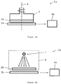
- Figure 1A a structure of an optoelectronic angle sensor 1a is sketched for determining a rotation angle about an axis.
- An around the axis 6 - axis of rotation - arranged disc 2a as a code carrier is inserted into a skirt 5.
- the enclosure 5 is connected to a tool or a motor.
- the enclosure 5 can also be inserted into the alhidade of a theodolite and rotate with it.
- the circular disc 2a rotates - as indicated by the arrow - with respect to an electro-optical detector 3a, which is arranged relative to the circular disc 2a such that on the detector 3a facing surface of the circular disc 2a applied code elements are imaged on the detector 3a.
- Circular disk 2a and detector 3a are coaxial here centered.
- the image - or the angle-proportional measurement signals - is further processed in an electronic component 4a as a memory and evaluation component.
- an electronic reference pattern which can be variably parametrically varied by a parameter, is stored in the electronic component 4a, which is compared with the measurement signals. Based on a parameter estimate, the angle of rotation about the axis 6 is determined.
- FIG. 1B shows an angle sensor 1b with a relative to a detector 3b rotatable disc 2b and a radiation source 7 of an imaging device.
- the detector 3b is substantially the same size as the circular disc 2b.
- Radiation source 7 and disc 2b are arranged in a common - shown by dashed lines - housing 8, so that the radiation source 7 and disc 2b rotate together.
- the radiation source 7 can also be arranged outside the rotating parts and be stationary.
- the detector 3b may be formed and arranged as a rotating component.
- the circular disc 2b is made of optically transparent material, such as glass or plastic, and has - not shown - for the radiation transmissive and impermeable areas as coding.
- a memory and evaluation component 4b For example, an FPGA (field-programmable gate array), compared with an electronic reference pattern and determined in the comparison process of the rotation angle.
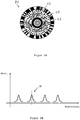
- FIG. 2A an embodiment of a circular disc 2c of an inventive optoelectronic angle sensor is shown.
- the circular disc 2c carries a largely full-surface coding, which here has a first, second and third sub-code.
- the first subcode is an azimuthally extended binary absolute code c1 applied in the outer area of the circular disk 2c.
- the second subcode is executed as a polar distributed point code c2.
- the concentric circles c3 around the circular disc center form the third subcode.
- the circular disc 2c shown enables the determination of the rotation angle by means of the following steps:
- the coding is imaged on the detector so that the first, second and third partial codes are largely completely - for example 95% - detected. From the image of the absolute code c1, a coarse value of the rotation angle can be determined.
- the measurement signals representing the image of the point code c2 are algorithmically compared with the idealized data of an imaging model of the point code c2 forming the reference pattern on the basis of a correlation formation.
- the point code c2 on the circular disc 2c is an ambiguous code, so provides no unique position information.
- the correlation of the idealized data with the measurement signals results in several correlation peaks, as in the representation of the correlation of the data as a function of the rotation angle FIG. 2B shown.
- the relevant angular interval and the correct correlation peak p selected.
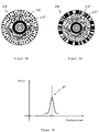
- the FIG. 3A shows a circular disc 2d with two sub-codes as coding, the rotation angle is basically determined from the image and the evaluation of the polar distributed point code c4 as a partial code.
- the illustrated further sub-code - the azimuthally extended radial code c3 '- is provided for eliminating eccentricity and Achstaumelschreibn.
- the circumferentially and radially extending, polar distributed point code c4 carries a unique position information.
- the desired rotation angle is determined as the angle of rotation associated with the maximum correlation value.
- the circular disk 2e in FIG. 3B has one for coding FIG. 2B similar full-surface coding on.
- the dot code c4 'of the middle code track is like the dot code off FIG. 3A , clearly.
- the absolute code c2 'of the outer code track is provided to obtain an initial value for the software-performed correlation formation of the point code c4' with a reference pattern. This accelerates the formation of the correlation and reduces the required computer power.
- an angle value determined from the absolute code c2 ' may be used as an initial value in an angle-dependent function representing the reference pattern and varied until the correlation reaches a maximum or a predetermined correlation value.
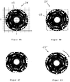
- 4A is an absolutely coded circular disk 2f of an angle sensor with a, applied substantially over the entire disk surface, binary code c5 shown in a coordinate system in the 0 ° -angle position.
- the binary code c5 is formed of translucent and opaque code elements and varies depending on the angle in both the azimuthal and radial directions.
- the representation of the binary code c5 is purely exemplary.
- the circular disc 2f is miniaturized. By virtue of the fact that the binary code c5 is applied essentially over the entire surface, a high number of transitions-and thus coding with a high information content-can nevertheless be achieved. Since the circular disc 2f is miniaturized, an economical embodiment of an angle sensor with a detector whose surface corresponds approximately to the surface of the circular disc can be realized.
- FIG. 4B shows the circular disc 2f after a rotation by about 45 °.
- the position of a flat photosensitive detector of the angle sensor is also shown with dashed lines.
- a largely complete evaluable image of the coding can be generated on the detector.
- an evaluation method is used for angle determination, which makes it possible to evaluate the imaged code structures.
- the evaluation method here comprises the provision of a electronic reference pattern, which describes a statistical distribution of a random variable - in this case the rotation angle - the description is based on an estimator.
- the measurement function - the image - and the estimation function are compared with each other, whereby the random variable - the rotation angle - is systematically changed.
- the comparison or the estimate provides a best estimator for the angle of rotation.
- FIG. 4C represents the area of the binary code c5 which is imaged as an image on the detector.
- Figure 4D shows a pictorial, purely illustrative, representation of a reference pattern, which duplicates the binary code c5.
- the reference pattern is a replica c5 'of the binary code c5 at the 0 ° position - reference position - off FIG. 4A drawn.
- the actual replication takes place by means of an appropriate software.
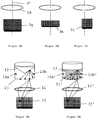
- FIG. 5A corresponds to the detecting surface of the detector 3g approximately the surface of the circular disc 2g, so that substantially the entire applied to the disc 2g coding can be mapped in a simple manner to the detector 3g.
- the detector 2g is eg a 1000 x 1000 CMOS pixel sensor.
- the axis of rotation 6 'of the angle sensor coincides with the geometric axes of circular disk 2g and detector 3g - circular disk 2g and detector 3g are arranged coaxially centered. This is also in FIG. 5B the case.
- FIG. 5C shows an embodiment with a detector 3i whose center does not coincide with the axis of rotation of the angle sensor.
- the means for imaging and the storage and evaluation component of the angle sensor are not shown.
- the device for generating the image is designed and arranged such that the largest possible, in particular the entire, region of the coding of the circular disk is imaged on the detector elements.
- the image corresponds to electrical measurement signals which are compared pixel by pixel, for example, with ideal data derived from an imaging model of the coding or the image or, as described above, in an alternative manner with an alternative electronic reference pattern.
- the Figures 6A-6D are illustrations of an angle sensor with different means for generating an evaluable image of the circular disc encoding.
- the mapping of the coding can basically from the outside or inside in incident or transmitted light, or by a self-luminous code. Shown is only the lighting from the outside.
- the illumination is transmitted light: the radiation of two photodiodes 10a and 10b or 10a 'and 10b' is projected onto the circular disk 2j or 2j 'and to the detector 3j or by means of an optical unit exemplified here as a lens 11 or 11'. 3j 'shown.
- the radiation of the photodiodes 10a and 10b or 10a' and 10b ' is widened, in FIG. 6A by means of a scattering deflecting mirror 12 and in FIG. 6B through a scattering medium 13.
- the Figures 6C and 6D show the illumination of the disc in incident light.
- the radiation emitted by a radiation source 14 is irradiated in FIG. 6C directed by a beam splitter 15 on the circular disc 2k.
- the radiation reflected at the circular disk 2k passes through the beam splitter 15 via an imaging optical system 16 onto the detector 3k.
- the illumination takes place at an oblique incidence of the light of the radiation source 14 'on the circular disc 2k'.
- the reflected light is in turn directed to the detector 3k 'via imaging optics 16'.
- the imaging optics can each be formed from lenses with conical and / or spherical and / or aspherical surfaces.
Landscapes
- Physics & Mathematics (AREA)
- General Physics & Mathematics (AREA)
- Optical Transform (AREA)
- Length Measuring Devices By Optical Means (AREA)
- Light Receiving Elements (AREA)
Claims (14)
- Détecteur d'angle optoélectronique (1a, 1b) pour déterminer un angle de rotation autour d'un axe (6) avec• un disque circulaire (2a, 2b, 2c, 2d, 2e, 2f, 2g, 2k) rotatif autour de l'axe (6) avec un codage substantiellement intégral en surface,• un détecteur photosensible plat (3a, 3b, 3g, 3h, 3i, 3j, 3k), le disque circulaire (2a, 2b, 2c, 2d, 2e, 2f, 2g, 2k) et le détecteur étant mobiles l'un par rapport à l'autre,• un dispositif pour générer une image exploitable du codage sur le détecteur (3a, 3b, 3g, 3h, 3i, 3j, 3k) de telle manière que l'image contient une information sur la position relative du disque circulaire (2a, 2b, 2c, 2d, 2e, 2f, 2g, 2k) et du détecteur (3a, 3b, 3g, 3h, 3i, 3j, 3k) et• une composante de mémorisation et d'évaluation (4a, 4b) pour déterminer l'angle de rotation, cependant que le dispositif génère une image pratiquement complète, en particulier globale du codage,caractérisé en ce que la composante de mémorisation et d'évaluation (4a, 4b) met à disposition• un motif de référence électronique paramétré qui peut être associé au codage, en particulier basé sur modèle et• détermine l'angle de rotation à partir du motif de référence et de l'image d'un procédé de comparaison stochastique à paramètres variables.
- Détecteur d'angle optoélectronique (1a, 1b) selon la revendication 1, caractérisé en ce que l'image présente au moins 50%, en particulier plus de 75% et de préférence 100% du codage.
- Détecteur d'angle optoélectronique (1a, 1b) selon la revendication 1 ou 2, caractérisé en ce que les surfaces du détecteur (3a, 3b, 3g) et du disque circulaire (2a, 2b, 2g) sont adaptées l'une à l'autre dans leur dimensionnement, en particulier sont essentiellement coïncident.
- Détecteur d'angle optoélectronique (1a, 1b) selon l'une des revendications 1 à 3, caractérisé en ce que le disque circulaire (2a, 2b, 2g) et le détecteur (3a, 3b, 3g, 3h) sont placées centrées de manière coaxiale.
- Détecteur d'angle optoélectronique (1a, 1b) selon l'une des revendications précédentes, caractérisé en ce que le motif de référence est paramétré avec un angle de rotation de référence qui décrit la position en rotation du motif de référence par rapport à l'image.
- Détecteur d'angle optoélectronique (1a, 1b) selon l'une des revendications précédentes, caractérisé en ce que le motif de référence est basé sur• un modèle mathématique de l'image ou du codage ou• une duplication reproductrice ou une simulation de l'image ou du codage.
- Détecteur d'angle optoélectronique (1a, 1b) selon l'une des revendications précédentes, caractérisé en ce que le procédé de comparaison utilise un• procédé d'estimation, en particulier la méthode de maximum de vraisemblance ou la méthode des moindres carrés ou• un procédé de corrélation mathématique.
- Détecteur d'angle optoélectronique (1a, 1b) selon l'une des revendications précédentes, caractérisé en ce que le procédé de comparaison présente une pondération radiale de composants du codage.
- Détecteur d'angle optoélectronique (1a, 1b) selon l'une des revendications précédentes, caractérisé en ce que le codage présente• un code qui varie aussi bien dans le sens azimutal que dans le sens radial en fonction de l'angle (c5) et/ou• un code incrémentiel, par exemple une mire de Siemens et/ou• un code à points à répartition polaire (c2, c4) et/ou• un code absolu (c2') et/ou• un code radial qui s'étend dans le sens azimutal (c3')comme code partiel.
- Procédé pour déterminer un angle de rotation autour d'un axe (6) avec• un disque circulaire (2a, 2b, 2c, 2d, 2e, 2f, 2g, 2k) rotatif autour de l'axe (6) avec un codage substantiellement intégral en surface,• un détecteur photosensible plat (3a, 3b, 3g, 3h, 3i, 3j, 3k), le disque circulaire (2a, 2b, 2c, 2d, 2e, 2f, 2g, 2k) et le détecteur étant mobiles l'un par rapport à l'autre,avec une• génération d'une image exploitable pratiquement complète, en particulier globale du codage sur le détecteur (3a, 3b, 3g, 3h, 3i, 3j, 3k) de telle manière que l'image contient une information sur la position relative du disque circulaire (2a, 2b, 2c, 2d, 2e, 2f, 2g, 2k) et du détecteur (3a, 3b, 3g, 3h, 3i, 3j, 3k),• mise à disposition d'un motif de référence électronique qui peut être associé au codage, dont les paramètres varient par au moins un paramètre,• dérivation de l'angle de rotation par comparaison du motif de référence et de l'image et par variation du paramètre.
- Procédé selon la revendication 10, caractérisé en ce que le motif de référence est mis à disposition• en tant que modèle mathématique de l'image,• en tant que modèle mathématique du codage,• en tant que description algorithmique de l'image,• en tant que description algorithmique du codage,• en tant que simulation reproduisant l'image ou que duplication ou• en tant que simulation reproduisant le codage ou que duplication.
- Procédé selon la revendication 10 ou 11, caractérisé en ce que lors de la comparaison le motif de référence et l'image sont superposés numériquement.
- Procédé selon l'une des revendications 10 à 12, caractérisé en ce que lors de la dérivation on utilise• un procédé d'estimation, en particulier la méthode de maximum de vraisemblance ou la méthode des moindres carrés ou• un procédé de corrélation mathématique.
- Procédé selon l'une des revendications 10 à 13, caractérisé en ce que• on sélectionne comme paramètre un angle de rotation de référence qui décrit la position en rotation du motif de référence par rapport à l'image,• on exécute une estimation de paramètre selon la méthode de maximum de vraisemblance et• le on détermine l'angle de rotation comme étant le paramètre estimé.
Priority Applications (1)
| Application Number | Priority Date | Filing Date | Title |
|---|---|---|---|
| EP07786689.5A EP2052216B1 (fr) | 2006-08-18 | 2007-08-16 | Capteur angulaire optoélectronique et procédé destiné à la détermination d'un angle de rotation autour d'un axe |
Applications Claiming Priority (3)
| Application Number | Priority Date | Filing Date | Title |
|---|---|---|---|
| EP06119146A EP1890113A1 (fr) | 2006-08-18 | 2006-08-18 | Capteur angulaire optoélectronique et procédé destiné à la détermination d'un angle de rotation autour d'un axe |
| PCT/EP2007/007248 WO2008019855A1 (fr) | 2006-08-18 | 2007-08-16 | Capteur d'angle optoélectronique et procédé de détermination d'un angle de rotation autour d'un axe |
| EP07786689.5A EP2052216B1 (fr) | 2006-08-18 | 2007-08-16 | Capteur angulaire optoélectronique et procédé destiné à la détermination d'un angle de rotation autour d'un axe |
Publications (2)
| Publication Number | Publication Date |
|---|---|
| EP2052216A1 EP2052216A1 (fr) | 2009-04-29 |
| EP2052216B1 true EP2052216B1 (fr) | 2016-04-27 |
Family
ID=37600770
Family Applications (3)
| Application Number | Title | Priority Date | Filing Date |
|---|---|---|---|
| EP06119146A Withdrawn EP1890113A1 (fr) | 2006-08-18 | 2006-08-18 | Capteur angulaire optoélectronique et procédé destiné à la détermination d'un angle de rotation autour d'un axe |
| EP07786689.5A Active EP2052216B1 (fr) | 2006-08-18 | 2007-08-16 | Capteur angulaire optoélectronique et procédé destiné à la détermination d'un angle de rotation autour d'un axe |
| EP07801742.3A Active EP2052218B1 (fr) | 2006-08-18 | 2007-08-17 | Capteur angulaire optoélectronique et procédé destiné à la détermination d'un angle de rotation autour d'un axe |
Family Applications Before (1)
| Application Number | Title | Priority Date | Filing Date |
|---|---|---|---|
| EP06119146A Withdrawn EP1890113A1 (fr) | 2006-08-18 | 2006-08-18 | Capteur angulaire optoélectronique et procédé destiné à la détermination d'un angle de rotation autour d'un axe |
Family Applications After (1)
| Application Number | Title | Priority Date | Filing Date |
|---|---|---|---|
| EP07801742.3A Active EP2052218B1 (fr) | 2006-08-18 | 2007-08-17 | Capteur angulaire optoélectronique et procédé destiné à la détermination d'un angle de rotation autour d'un axe |
Country Status (7)
| Country | Link |
|---|---|
| US (2) | US8462979B2 (fr) |
| EP (3) | EP1890113A1 (fr) |
| JP (2) | JP5253394B2 (fr) |
| CN (2) | CN101506621B (fr) |
| AU (2) | AU2007286403B2 (fr) |
| CA (2) | CA2660999C (fr) |
| WO (2) | WO2008019855A1 (fr) |
Families Citing this family (24)
| Publication number | Priority date | Publication date | Assignee | Title |
|---|---|---|---|---|
| JP4989313B2 (ja) * | 2007-05-28 | 2012-08-01 | 株式会社トプコン | 絶対角度演算装置 |
| CN101952690B (zh) * | 2008-02-22 | 2013-02-27 | 特里伯耶拿有限公司 | 角度测量设备和方法 |
| EP2251647A1 (fr) | 2009-05-13 | 2010-11-17 | CSEM Centre Suisse d'Electronique et de Microtechnique SA - Recherche et Développement | Dispositif et méthode de mesure de position angulaire absolue |
| JP5690053B2 (ja) * | 2009-06-19 | 2015-03-25 | 株式会社エンプラス | ロータリエンコーダ |
| EP2372302A1 (fr) | 2010-03-26 | 2011-10-05 | Leica Geosystems AG | Procédé de mesure pour une machine de mesure mesurant les surfaces |
| EP2498076A1 (fr) | 2011-03-11 | 2012-09-12 | Hexagon Technology Center GmbH | Surveillance de l'usure d'une boîte de vitesse dans une centrale électrique |
| CN102322882A (zh) * | 2011-06-02 | 2012-01-18 | 浙江大学 | 基于阵列探测器的绝对轴角编码系统 |
| AT510674B1 (de) * | 2011-10-27 | 2014-05-15 | Avl List Gmbh | Verfahren und eine vorrichtung zum parametrieren eines sensors |
| US9541382B2 (en) | 2011-12-19 | 2017-01-10 | Kabushiki Kaisha Topcon | Rotation angle detecting apparatus and surveying instrument |
| JP6055179B2 (ja) * | 2011-12-19 | 2016-12-27 | 株式会社トプコン | 回転角検出装置及び測量装置 |
| EP2870433B1 (fr) * | 2012-07-04 | 2016-09-07 | Hexagon Technology Center GmbH | Indicateur de position optique avec mémoire analogique |
| EP2682718A1 (fr) * | 2012-07-05 | 2014-01-08 | Hexagon Technology Center GmbH | Procédé de saisie d'un codage absolu d'une piste de code optique |
| DE102012218890A1 (de) * | 2012-10-17 | 2014-04-17 | Dr. Johannes Heidenhain Gmbh | Absolutes Positionsmessgerät |
| EP2808653B1 (fr) | 2013-05-28 | 2016-07-13 | SICK STEGMANN GmbH | Capteur d´angle de rotation |
| CN103471529B (zh) * | 2013-09-26 | 2015-12-02 | 中国科学院长春光学精密机械与物理研究所 | 基于图像处理的高精度小型光电角度传感器 |
| US10252152B2 (en) * | 2015-02-11 | 2019-04-09 | Bmuse Group Llc | Moving object detection system and method |
| CN106951812B (zh) | 2017-03-31 | 2018-12-07 | 腾讯科技(深圳)有限公司 | 识别二维码的方法、装置和终端 |
| CN107590522B (zh) * | 2017-08-23 | 2020-08-21 | 阿里巴巴集团控股有限公司 | 一种识别码生成及识别的方法及装置 |
| CN108592960B (zh) * | 2018-05-10 | 2023-07-21 | 常州市新瑞得仪器有限公司 | 绝对值编码器及其工作方法 |
| DE102020200032A1 (de) * | 2020-01-03 | 2021-07-08 | Thyssenkrupp Ag | Wälzlager mit Positionsbestimmungseinrichtung |
| CN112857411B (zh) * | 2021-01-15 | 2022-10-14 | 广东工业大学 | 一种基于电流体喷印发光码道的旋转编码器及其测量方法 |
| CN113566854B (zh) * | 2021-07-06 | 2024-04-16 | 合肥工业大学 | 二进制编码盘和采用该二进制编码盘的层析成像系统 |
| DE102023203701A1 (de) * | 2023-04-21 | 2024-10-24 | Joyson Safety Systems Germany Gmbh | Verfahren und Einrichtung zur Absolutbestimmung eines Drehwinkels eines drehbaren Elements |
| CN118960664B (zh) * | 2024-10-15 | 2025-01-07 | 大连探索者科技有限公司 | 一种针对反射式光电角度传感器产品的测试评估方法 |
Citations (1)
| Publication number | Priority date | Publication date | Assignee | Title |
|---|---|---|---|---|
| EP0854436A2 (fr) * | 1997-01-17 | 1998-07-22 | Matsushita Electric Works, Ltd. | Système et procédé de detection de position |
Family Cites Families (26)
| Publication number | Priority date | Publication date | Assignee | Title |
|---|---|---|---|---|
| US3865428A (en) * | 1972-11-13 | 1975-02-11 | Carroll W Chester | Window shade for a vehicle or the like |
| US3862428A (en) * | 1973-10-11 | 1975-01-21 | United Aircraft Corp | Holographic spatial encoder |
| US4318225A (en) * | 1979-12-04 | 1982-03-09 | Mchenry Systems, Inc. | Angle measuring apparatus |
| JPS5847212A (ja) * | 1981-09-17 | 1983-03-18 | Fanuc Ltd | ロ−タリエンコ−ダ |
| JPS5931017U (ja) | 1982-08-20 | 1984-02-27 | ミノルタ株式会社 | パルスジエネレ−タ |
| JP2571689B2 (ja) | 1987-04-02 | 1997-01-16 | 株式会社スペース | 計測用標識 |
| DE3924460A1 (de) * | 1988-07-27 | 1990-02-01 | Litton Precision Prod Int | Winkelschrittgeber |
| US4953933A (en) * | 1989-07-10 | 1990-09-04 | The Boeing Company | Optical encoder reading device |
| US5563591A (en) | 1994-10-14 | 1996-10-08 | Xerox Corporation | Programmable encoder using an addressable display |
| JPH10206134A (ja) | 1997-01-17 | 1998-08-07 | Matsushita Electric Works Ltd | 画像処理による位置検出方法 |
| JPH10253393A (ja) | 1997-03-10 | 1998-09-25 | Yaskawa Electric Corp | アブソリュートエンコーダ |
| DE19750474C2 (de) * | 1997-11-14 | 2000-08-10 | Stegmann Max Antriebstech | Drehgeber |
| DE19944004A1 (de) * | 1999-09-14 | 2001-03-15 | Kostal Leopold Gmbh & Co Kg | Optoelektronischer Drehwinkelsensor |
| ES2293878T3 (es) * | 1999-09-28 | 2008-04-01 | Snap-On Equipment Gmbh | Maquina de equilibrado de ruedas para una rueda de automovil con codificador angular compacto. |
| DE10006675C2 (de) * | 2000-02-15 | 2002-05-16 | Kostal Leopold Gmbh & Co Kg | Codescheibe für eine optoelektronische Weg- oder Winkelmeßeinrichtung |
| JP4444469B2 (ja) * | 2000-08-07 | 2010-03-31 | 株式会社ミツトヨ | 光学式変位測定装置 |
| DE10325108A1 (de) * | 2003-06-03 | 2005-01-05 | Trw Automotive Electronics & Components Gmbh & Co. Kg | Optoelektronischer Drehwinkelsensor |
| SE0301164D0 (sv) * | 2003-04-22 | 2003-04-22 | Trimble Ab | Improved high accuracy absolute optical encoder |
| JP2004347382A (ja) | 2003-05-21 | 2004-12-09 | Microsignal Kk | 光学式エンコーダ |
| WO2005015132A1 (fr) * | 2003-08-06 | 2005-02-17 | Hamamatsu Photonics K.K. | Codeur absolu |
| US7078677B2 (en) * | 2004-01-21 | 2006-07-18 | Chee Keong Chong | Optical encoder disk having a region that continuously increases in size |
| US7145127B2 (en) * | 2004-08-25 | 2006-12-05 | Avago Technologies Ecbu Ip (Singapore) Pte. Ltd. | Optical encoding that utilizes total internal reflection |
| ES2298982T3 (es) * | 2005-05-13 | 2008-05-16 | Fagor, S.Coop. | Dispositivo optoelectronico de medida. |
| EP1790953A1 (fr) * | 2005-11-04 | 2007-05-30 | Leica Geosystems AG | Dispositif de mesure d'angle optoélectronique |
| US7462815B2 (en) * | 2005-12-13 | 2008-12-09 | Avago Technologies General Ip (Singapore) Pte. Ltd. | Absolute encoder utilizing a code pattern carrier having a varying mixture of phosphors deposited thereon |
| JP5053173B2 (ja) * | 2008-05-16 | 2012-10-17 | 富士フイルム株式会社 | 位置検出センサ |
-
2006
- 2006-08-18 EP EP06119146A patent/EP1890113A1/fr not_active Withdrawn
-
2007
- 2007-08-16 WO PCT/EP2007/007248 patent/WO2008019855A1/fr not_active Ceased
- 2007-08-16 CA CA2660999A patent/CA2660999C/fr not_active Expired - Fee Related
- 2007-08-16 EP EP07786689.5A patent/EP2052216B1/fr active Active
- 2007-08-16 CN CN2007800306566A patent/CN101506621B/zh not_active Expired - Fee Related
- 2007-08-16 US US12/377,445 patent/US8462979B2/en active Active
- 2007-08-16 AU AU2007286403A patent/AU2007286403B2/en not_active Ceased
- 2007-08-16 JP JP2009524127A patent/JP5253394B2/ja not_active Expired - Fee Related
- 2007-08-17 AU AU2007286424A patent/AU2007286424B2/en not_active Ceased
- 2007-08-17 JP JP2009524133A patent/JP5260518B2/ja not_active Expired - Fee Related
- 2007-08-17 US US12/377,462 patent/US8242434B2/en active Active
- 2007-08-17 CA CA2660369A patent/CA2660369C/fr not_active Expired - Fee Related
- 2007-08-17 WO PCT/EP2007/007302 patent/WO2008019876A1/fr not_active Ceased
- 2007-08-17 EP EP07801742.3A patent/EP2052218B1/fr active Active
- 2007-08-17 CN CN2007800302546A patent/CN101501455B/zh not_active Expired - Fee Related
Patent Citations (1)
| Publication number | Priority date | Publication date | Assignee | Title |
|---|---|---|---|---|
| EP0854436A2 (fr) * | 1997-01-17 | 1998-07-22 | Matsushita Electric Works, Ltd. | Système et procédé de detection de position |
Also Published As
| Publication number | Publication date |
|---|---|
| EP1890113A1 (fr) | 2008-02-20 |
| EP2052218B1 (fr) | 2016-04-20 |
| CN101501455B (zh) | 2011-11-09 |
| AU2007286403A1 (en) | 2008-02-21 |
| JP5253394B2 (ja) | 2013-07-31 |
| AU2007286424A1 (en) | 2008-02-21 |
| US20110044561A1 (en) | 2011-02-24 |
| CA2660369A1 (fr) | 2008-02-21 |
| CN101506621B (zh) | 2010-12-15 |
| WO2008019876B1 (fr) | 2008-05-02 |
| CA2660369C (fr) | 2014-09-30 |
| CA2660999C (fr) | 2016-02-09 |
| WO2008019855A1 (fr) | 2008-02-21 |
| JP2010501071A (ja) | 2010-01-14 |
| EP2052218A1 (fr) | 2009-04-29 |
| AU2007286403B2 (en) | 2011-10-13 |
| EP2052216A1 (fr) | 2009-04-29 |
| US8462979B2 (en) | 2013-06-11 |
| US20110315864A1 (en) | 2011-12-29 |
| JP2010501068A (ja) | 2010-01-14 |
| US8242434B2 (en) | 2012-08-14 |
| CN101506621A (zh) | 2009-08-12 |
| CA2660999A1 (fr) | 2008-02-21 |
| CN101501455A (zh) | 2009-08-05 |
| WO2008019876A1 (fr) | 2008-02-21 |
| JP5260518B2 (ja) | 2013-08-14 |
| AU2007286424B2 (en) | 2011-11-03 |
Similar Documents
| Publication | Publication Date | Title |
|---|---|---|
| EP2052216B1 (fr) | Capteur angulaire optoélectronique et procédé destiné à la détermination d'un angle de rotation autour d'un axe | |
| DE112008003711B4 (de) | Winkelmessgerät und -verfahren | |
| EP2118555B1 (fr) | Dispositif de sécurité pour une machine | |
| DE102017118767A1 (de) | Verfahren und Vorrichtung zum Bestimmen von dimensionellen und/oder geometrischen Eigenschaften eines Messobjekts | |
| EP2764336A1 (fr) | Spectromètre à foyer commun et procédé d'imagerie dans un spectromètre à foyer commun | |
| EP2092486B1 (fr) | Procédé pour évaluer une image à l'aide de repères d'image | |
| EP3699640B1 (fr) | Capteur optoélectronique et procédé de détection d'un objet | |
| EP2101143A1 (fr) | Procédé et dispositif destinés à la saisie de la forme d'objets réfractifs transparents | |
| EP2737288A1 (fr) | Spectromètre à foyer commun et procédé d'imagerie dans un spectromètre à foyer commun | |
| DE3884474T2 (de) | Drehpositionskodierer. | |
| EP2808653B1 (fr) | Capteur d´angle de rotation | |
| EP1188035A1 (fr) | Procede et dispositif de balayage d'objets | |
| DE112019004295T5 (de) | Optischer kodierer | |
| EP1477774B1 (fr) | Dispositif de mesure de position | |
| DE1958136A1 (de) | Optische Einrichtung zum Abtasten von Winkelbewegungen | |
| EP3807619B1 (fr) | Disque perforé pour la sélection de lumière pour une reproduction optique | |
| EP2657653B1 (fr) | Dispositif de mesure de l'angle de rotation de deux objets tournant l'un par rapport à l'autre autour d'un axe | |
| DE102004035172A1 (de) | Positionsmesseinrichtung | |
| EP1245931A1 (fr) | Procédé pour l'étalonage d'un instrument de mesure | |
| DE102019209902A1 (de) | Optischer winkelsensor | |
| DE102021110583B4 (de) | Gebervorrichtung und Verfahren zur Bestimmung einer Absolutposition | |
| DE102006052047A1 (de) | Verfahren und Vorrichtung zur Bestimmung der Lage einer Symmetrieachse einer asphärischen Linsenfläche | |
| EP4367548A1 (fr) | Système de mesure optique basé sur un éclairage pour éclairer un objet de test optique, et procédé de fonctionnement d'un système de mesure optique basé sur un éclairage | |
| DE3511347C2 (de) | Verfahren und Vorrichtung zur optischen mehrdimensionalen Formerfassung eines Objekts | |
| EP2950056B1 (fr) | Dispositif de mesure d'un angle de rotation et procédé de détermination d'un angle de rotation |
Legal Events
| Date | Code | Title | Description |
|---|---|---|---|
| PUAI | Public reference made under article 153(3) epc to a published international application that has entered the european phase |
Free format text: ORIGINAL CODE: 0009012 |
|
| 17P | Request for examination filed |
Effective date: 20090108 |
|
| AK | Designated contracting states |
Kind code of ref document: A1 Designated state(s): AT BE BG CH CY CZ DE DK EE ES FI FR GB GR HU IE IS IT LI LT LU LV MC MT NL PL PT RO SE SI SK TR |
|
| AX | Request for extension of the european patent |
Extension state: AL BA HR MK RS |
|
| DAX | Request for extension of the european patent (deleted) | ||
| 17Q | First examination report despatched |
Effective date: 20130107 |
|
| GRAP | Despatch of communication of intention to grant a patent |
Free format text: ORIGINAL CODE: EPIDOSNIGR1 |
|
| INTG | Intention to grant announced |
Effective date: 20160122 |
|
| GRAS | Grant fee paid |
Free format text: ORIGINAL CODE: EPIDOSNIGR3 |
|
| GRAA | (expected) grant |
Free format text: ORIGINAL CODE: 0009210 |
|
| AK | Designated contracting states |
Kind code of ref document: B1 Designated state(s): AT BE BG CH CY CZ DE DK EE ES FI FR GB GR HU IE IS IT LI LT LU LV MC MT NL PL PT RO SE SI SK TR |
|
| REG | Reference to a national code |
Ref country code: GB Ref legal event code: FG4D Free format text: NOT ENGLISH |
|
| REG | Reference to a national code |
Ref country code: CH Ref legal event code: EP |
|
| REG | Reference to a national code |
Ref country code: CH Ref legal event code: NV Representative=s name: KAMINSKI HARMANN PATENTANWAELTE AG, LI |
|
| REG | Reference to a national code |
Ref country code: AT Ref legal event code: REF Ref document number: 795313 Country of ref document: AT Kind code of ref document: T Effective date: 20160515 |
|
| REG | Reference to a national code |
Ref country code: IE Ref legal event code: FG4D Free format text: LANGUAGE OF EP DOCUMENT: GERMAN |
|
| REG | Reference to a national code |
Ref country code: DE Ref legal event code: R096 Ref document number: 502007014766 Country of ref document: DE |
|
| REG | Reference to a national code |
Ref country code: SE Ref legal event code: TRGR |
|
| REG | Reference to a national code |
Ref country code: NL Ref legal event code: FP |
|
| REG | Reference to a national code |
Ref country code: FR Ref legal event code: PLFP Year of fee payment: 10 |
|
| REG | Reference to a national code |
Ref country code: LT Ref legal event code: MG4D |
|
| PG25 | Lapsed in a contracting state [announced via postgrant information from national office to epo] |
Ref country code: FI Free format text: LAPSE BECAUSE OF FAILURE TO SUBMIT A TRANSLATION OF THE DESCRIPTION OR TO PAY THE FEE WITHIN THE PRESCRIBED TIME-LIMIT Effective date: 20160427 Ref country code: PL Free format text: LAPSE BECAUSE OF FAILURE TO SUBMIT A TRANSLATION OF THE DESCRIPTION OR TO PAY THE FEE WITHIN THE PRESCRIBED TIME-LIMIT Effective date: 20160427 Ref country code: LT Free format text: LAPSE BECAUSE OF FAILURE TO SUBMIT A TRANSLATION OF THE DESCRIPTION OR TO PAY THE FEE WITHIN THE PRESCRIBED TIME-LIMIT Effective date: 20160427 |
|
| PG25 | Lapsed in a contracting state [announced via postgrant information from national office to epo] |
Ref country code: LV Free format text: LAPSE BECAUSE OF FAILURE TO SUBMIT A TRANSLATION OF THE DESCRIPTION OR TO PAY THE FEE WITHIN THE PRESCRIBED TIME-LIMIT Effective date: 20160427 Ref country code: GR Free format text: LAPSE BECAUSE OF FAILURE TO SUBMIT A TRANSLATION OF THE DESCRIPTION OR TO PAY THE FEE WITHIN THE PRESCRIBED TIME-LIMIT Effective date: 20160728 Ref country code: ES Free format text: LAPSE BECAUSE OF FAILURE TO SUBMIT A TRANSLATION OF THE DESCRIPTION OR TO PAY THE FEE WITHIN THE PRESCRIBED TIME-LIMIT Effective date: 20160427 Ref country code: PT Free format text: LAPSE BECAUSE OF FAILURE TO SUBMIT A TRANSLATION OF THE DESCRIPTION OR TO PAY THE FEE WITHIN THE PRESCRIBED TIME-LIMIT Effective date: 20160829 |
|
| PG25 | Lapsed in a contracting state [announced via postgrant information from national office to epo] |
Ref country code: IT Free format text: LAPSE BECAUSE OF FAILURE TO SUBMIT A TRANSLATION OF THE DESCRIPTION OR TO PAY THE FEE WITHIN THE PRESCRIBED TIME-LIMIT Effective date: 20160427 Ref country code: BE Free format text: LAPSE BECAUSE OF NON-PAYMENT OF DUE FEES Effective date: 20160831 |
|
| REG | Reference to a national code |
Ref country code: DE Ref legal event code: R097 Ref document number: 502007014766 Country of ref document: DE |
|
| PG25 | Lapsed in a contracting state [announced via postgrant information from national office to epo] |
Ref country code: EE Free format text: LAPSE BECAUSE OF FAILURE TO SUBMIT A TRANSLATION OF THE DESCRIPTION OR TO PAY THE FEE WITHIN THE PRESCRIBED TIME-LIMIT Effective date: 20160427 Ref country code: SK Free format text: LAPSE BECAUSE OF FAILURE TO SUBMIT A TRANSLATION OF THE DESCRIPTION OR TO PAY THE FEE WITHIN THE PRESCRIBED TIME-LIMIT Effective date: 20160427 Ref country code: RO Free format text: LAPSE BECAUSE OF FAILURE TO SUBMIT A TRANSLATION OF THE DESCRIPTION OR TO PAY THE FEE WITHIN THE PRESCRIBED TIME-LIMIT Effective date: 20160427 Ref country code: DK Free format text: LAPSE BECAUSE OF FAILURE TO SUBMIT A TRANSLATION OF THE DESCRIPTION OR TO PAY THE FEE WITHIN THE PRESCRIBED TIME-LIMIT Effective date: 20160427 Ref country code: CZ Free format text: LAPSE BECAUSE OF FAILURE TO SUBMIT A TRANSLATION OF THE DESCRIPTION OR TO PAY THE FEE WITHIN THE PRESCRIBED TIME-LIMIT Effective date: 20160427 |
|
| PLBE | No opposition filed within time limit |
Free format text: ORIGINAL CODE: 0009261 |
|
| STAA | Information on the status of an ep patent application or granted ep patent |
Free format text: STATUS: NO OPPOSITION FILED WITHIN TIME LIMIT |
|
| PG25 | Lapsed in a contracting state [announced via postgrant information from national office to epo] |
Ref country code: MC Free format text: LAPSE BECAUSE OF FAILURE TO SUBMIT A TRANSLATION OF THE DESCRIPTION OR TO PAY THE FEE WITHIN THE PRESCRIBED TIME-LIMIT Effective date: 20160427 |
|
| 26N | No opposition filed |
Effective date: 20170130 |
|
| PG25 | Lapsed in a contracting state [announced via postgrant information from national office to epo] |
Ref country code: SI Free format text: LAPSE BECAUSE OF FAILURE TO SUBMIT A TRANSLATION OF THE DESCRIPTION OR TO PAY THE FEE WITHIN THE PRESCRIBED TIME-LIMIT Effective date: 20160427 |
|
| REG | Reference to a national code |
Ref country code: IE Ref legal event code: MM4A |
|
| PG25 | Lapsed in a contracting state [announced via postgrant information from national office to epo] |
Ref country code: IE Free format text: LAPSE BECAUSE OF NON-PAYMENT OF DUE FEES Effective date: 20160816 |
|
| REG | Reference to a national code |
Ref country code: FR Ref legal event code: PLFP Year of fee payment: 11 |
|
| PG25 | Lapsed in a contracting state [announced via postgrant information from national office to epo] |
Ref country code: LU Free format text: LAPSE BECAUSE OF NON-PAYMENT OF DUE FEES Effective date: 20160816 |
|
| REG | Reference to a national code |
Ref country code: AT Ref legal event code: MM01 Ref document number: 795313 Country of ref document: AT Kind code of ref document: T Effective date: 20160816 |
|
| PG25 | Lapsed in a contracting state [announced via postgrant information from national office to epo] |
Ref country code: AT Free format text: LAPSE BECAUSE OF NON-PAYMENT OF DUE FEES Effective date: 20160816 |
|
| PG25 | Lapsed in a contracting state [announced via postgrant information from national office to epo] |
Ref country code: HU Free format text: LAPSE BECAUSE OF FAILURE TO SUBMIT A TRANSLATION OF THE DESCRIPTION OR TO PAY THE FEE WITHIN THE PRESCRIBED TIME-LIMIT; INVALID AB INITIO Effective date: 20070816 Ref country code: CY Free format text: LAPSE BECAUSE OF FAILURE TO SUBMIT A TRANSLATION OF THE DESCRIPTION OR TO PAY THE FEE WITHIN THE PRESCRIBED TIME-LIMIT Effective date: 20160427 |
|
| PG25 | Lapsed in a contracting state [announced via postgrant information from national office to epo] |
Ref country code: TR Free format text: LAPSE BECAUSE OF FAILURE TO SUBMIT A TRANSLATION OF THE DESCRIPTION OR TO PAY THE FEE WITHIN THE PRESCRIBED TIME-LIMIT Effective date: 20160427 Ref country code: IS Free format text: LAPSE BECAUSE OF FAILURE TO SUBMIT A TRANSLATION OF THE DESCRIPTION OR TO PAY THE FEE WITHIN THE PRESCRIBED TIME-LIMIT Effective date: 20160427 Ref country code: MT Free format text: LAPSE BECAUSE OF FAILURE TO SUBMIT A TRANSLATION OF THE DESCRIPTION OR TO PAY THE FEE WITHIN THE PRESCRIBED TIME-LIMIT Effective date: 20160427 |
|
| PG25 | Lapsed in a contracting state [announced via postgrant information from national office to epo] |
Ref country code: BG Free format text: LAPSE BECAUSE OF FAILURE TO SUBMIT A TRANSLATION OF THE DESCRIPTION OR TO PAY THE FEE WITHIN THE PRESCRIBED TIME-LIMIT Effective date: 20160427 |
|
| REG | Reference to a national code |
Ref country code: FR Ref legal event code: PLFP Year of fee payment: 12 |
|
| PGFP | Annual fee paid to national office [announced via postgrant information from national office to epo] |
Ref country code: NL Payment date: 20190821 Year of fee payment: 13 |
|
| PGFP | Annual fee paid to national office [announced via postgrant information from national office to epo] |
Ref country code: SE Payment date: 20190821 Year of fee payment: 13 |
|
| PGFP | Annual fee paid to national office [announced via postgrant information from national office to epo] |
Ref country code: CH Payment date: 20190821 Year of fee payment: 13 |
|
| REG | Reference to a national code |
Ref country code: SE Ref legal event code: EUG |
|
| REG | Reference to a national code |
Ref country code: CH Ref legal event code: PL |
|
| REG | Reference to a national code |
Ref country code: NL Ref legal event code: MM Effective date: 20200901 |
|
| PG25 | Lapsed in a contracting state [announced via postgrant information from national office to epo] |
Ref country code: LI Free format text: LAPSE BECAUSE OF NON-PAYMENT OF DUE FEES Effective date: 20200831 Ref country code: CH Free format text: LAPSE BECAUSE OF NON-PAYMENT OF DUE FEES Effective date: 20200831 |
|
| PG25 | Lapsed in a contracting state [announced via postgrant information from national office to epo] |
Ref country code: SE Free format text: LAPSE BECAUSE OF NON-PAYMENT OF DUE FEES Effective date: 20200817 |
|
| PG25 | Lapsed in a contracting state [announced via postgrant information from national office to epo] |
Ref country code: NL Free format text: LAPSE BECAUSE OF NON-PAYMENT OF DUE FEES Effective date: 20200901 |
|
| PGFP | Annual fee paid to national office [announced via postgrant information from national office to epo] |
Ref country code: DE Payment date: 20250820 Year of fee payment: 19 |
|
| PGFP | Annual fee paid to national office [announced via postgrant information from national office to epo] |
Ref country code: GB Payment date: 20250820 Year of fee payment: 19 |
|
| PGFP | Annual fee paid to national office [announced via postgrant information from national office to epo] |
Ref country code: FR Payment date: 20250829 Year of fee payment: 19 |