EP2052216B1 - Optoelectronic angle sensor and method for determining a rotation angle around an axis - Google Patents
Optoelectronic angle sensor and method for determining a rotation angle around an axis Download PDFInfo
- Publication number
- EP2052216B1 EP2052216B1 EP07786689.5A EP07786689A EP2052216B1 EP 2052216 B1 EP2052216 B1 EP 2052216B1 EP 07786689 A EP07786689 A EP 07786689A EP 2052216 B1 EP2052216 B1 EP 2052216B1
- Authority
- EP
- European Patent Office
- Prior art keywords
- coding
- image
- detector
- code
- angle sensor
- Prior art date
- Legal status (The legal status is an assumption and is not a legal conclusion. Google has not performed a legal analysis and makes no representation as to the accuracy of the status listed.)
- Active
Links
Images

Classifications
-
- G—PHYSICS
- G01—MEASURING; TESTING
- G01D—MEASURING NOT SPECIALLY ADAPTED FOR A SPECIFIC VARIABLE; ARRANGEMENTS FOR MEASURING TWO OR MORE VARIABLES NOT COVERED IN A SINGLE OTHER SUBCLASS; TARIFF METERING APPARATUS; MEASURING OR TESTING NOT OTHERWISE PROVIDED FOR
- G01D5/00—Mechanical means for transferring the output of a sensing member; Means for converting the output of a sensing member to another variable where the form or nature of the sensing member does not constrain the means for converting; Transducers not specially adapted for a specific variable
- G01D5/26—Mechanical means for transferring the output of a sensing member; Means for converting the output of a sensing member to another variable where the form or nature of the sensing member does not constrain the means for converting; Transducers not specially adapted for a specific variable characterised by optical transfer means, i.e. using infrared, visible, or ultraviolet light
- G01D5/32—Mechanical means for transferring the output of a sensing member; Means for converting the output of a sensing member to another variable where the form or nature of the sensing member does not constrain the means for converting; Transducers not specially adapted for a specific variable characterised by optical transfer means, i.e. using infrared, visible, or ultraviolet light with attenuation or whole or partial obturation of beams of light
- G01D5/34—Mechanical means for transferring the output of a sensing member; Means for converting the output of a sensing member to another variable where the form or nature of the sensing member does not constrain the means for converting; Transducers not specially adapted for a specific variable characterised by optical transfer means, i.e. using infrared, visible, or ultraviolet light with attenuation or whole or partial obturation of beams of light the beams of light being detected by photocells
- G01D5/347—Mechanical means for transferring the output of a sensing member; Means for converting the output of a sensing member to another variable where the form or nature of the sensing member does not constrain the means for converting; Transducers not specially adapted for a specific variable characterised by optical transfer means, i.e. using infrared, visible, or ultraviolet light with attenuation or whole or partial obturation of beams of light the beams of light being detected by photocells using displacement encoding scales
- G01D5/34776—Absolute encoders with analogue or digital scales
-
- G—PHYSICS
- G01—MEASURING; TESTING
- G01D—MEASURING NOT SPECIALLY ADAPTED FOR A SPECIFIC VARIABLE; ARRANGEMENTS FOR MEASURING TWO OR MORE VARIABLES NOT COVERED IN A SINGLE OTHER SUBCLASS; TARIFF METERING APPARATUS; MEASURING OR TESTING NOT OTHERWISE PROVIDED FOR
- G01D5/00—Mechanical means for transferring the output of a sensing member; Means for converting the output of a sensing member to another variable where the form or nature of the sensing member does not constrain the means for converting; Transducers not specially adapted for a specific variable
- G01D5/26—Mechanical means for transferring the output of a sensing member; Means for converting the output of a sensing member to another variable where the form or nature of the sensing member does not constrain the means for converting; Transducers not specially adapted for a specific variable characterised by optical transfer means, i.e. using infrared, visible, or ultraviolet light
- G01D5/32—Mechanical means for transferring the output of a sensing member; Means for converting the output of a sensing member to another variable where the form or nature of the sensing member does not constrain the means for converting; Transducers not specially adapted for a specific variable characterised by optical transfer means, i.e. using infrared, visible, or ultraviolet light with attenuation or whole or partial obturation of beams of light
- G01D5/34—Mechanical means for transferring the output of a sensing member; Means for converting the output of a sensing member to another variable where the form or nature of the sensing member does not constrain the means for converting; Transducers not specially adapted for a specific variable characterised by optical transfer means, i.e. using infrared, visible, or ultraviolet light with attenuation or whole or partial obturation of beams of light the beams of light being detected by photocells
- G01D5/347—Mechanical means for transferring the output of a sensing member; Means for converting the output of a sensing member to another variable where the form or nature of the sensing member does not constrain the means for converting; Transducers not specially adapted for a specific variable characterised by optical transfer means, i.e. using infrared, visible, or ultraviolet light with attenuation or whole or partial obturation of beams of light the beams of light being detected by photocells using displacement encoding scales
- G01D5/3473—Circular or rotary encoders
Definitions
- the invention relates to an optoelectronic angle sensor according to the preamble of claim 1 and to a method for determining a rotation angle about an axis according to claim 10.
- optoelectronic angle sensors for determining a rotation angle about an axis comprise a code carrier and an optical detector, which are rotatable relative to each other.
- the optical detector is, for example, a photodetector, a CCD line array or a CCD area array.
- the code carrier is generally designed as a circular disk or as a circular ring and carries along its circumference an optically detectable position code, of which a section is imaged onto the detector.
- the detector is generally much smaller than the code carrier. To miniaturize the angle sensor therefore a reduction of the code carrier is required in the first place. With a code carrier with a reduced diameter, the ratio of detector area to code carrier area can be increased and thus a larger area of the code applied to the code carrier can be detected. In addition, for an angle sensor with the code carrier as a rotating component and the detector as a fixed component, a higher operating stability can be achieved because of the on the Reduce code carrier acting centrifugal forces. In general, the code carrier of the angle sensor rotates. However, it is also possible to fix the code carrier and make the detector rotating.
- the coding can not be arbitrarily refined insofar as ever finer structures ever greater diffraction effects occur and the structures can not be resolved with the required accuracy.
- the angular resolution is determined by the resolution of the coding by means of the detector and thus depends on the resolving power of the detector. However, this is limited because a reduction of the pixel size is limited by the signal-to-noise ratio. Alternatively, a higher angular resolution can be achieved by increasing the diameter of the code carrier, which is in contradiction to all Miniaturmaschinesbestrebache.
- angle sensor designs are downsized by reducing optical or mechanical components.
- the DE 197 50 474 A1 describes a reduction of the diameter of a partial disk of an angle sensor by the dividing disk in the axis of the rotating shaft directly is used.
- the diameter of the dividing disc around an outer enclosure, such as a metal ring, the same can be reduced.
- this mechanical solution allows only the reduction of the part of disc around the outer enclosure and therefore offers only scope for a reduction of the angle sensor in the range of a few percent. It does not provide any possibility to substantially reduce the diameter of the code-bearing surface of the sensor, for example by 80%, and thus to miniaturize the angle sensor.
- the document DE 3924360 discloses a rotation angle sensor according to the prior art.
- Another object of the invention is to provide an opto-electronic angle sensor improved in terms of accuracy of angle determination.
- a further object is to provide a method for determining a rotation angle, which enables the rotation angle determination with a code carrier with a reduced diameter.
- Another object is to provide a method for determining a rotation angle with improved accuracy.
- the invention is based on the fact that the coding of the circular disk of an optoelectronic angle sensor according to the invention is largely completely captured as an image and the captured images-or the detector measurement signals-are interpreted as realizations of a statistical parameter.
- the parameter value characterizing the measurement signals is determined from a constructed distribution of parameter values.
- a substantially complete, in particular overall, evaluatable image of the coding of the circular disk is generated on the detector of the angle sensor.
- 90% of the encoding is captured as an image.
- the image includes information about the relative position of the circular disc and the detector, which are movable relative to each other.
- the relative movement comprises at least one relative rotational movement about an axis.
- the circular disk and the detector can also detect extremely small translatory relative movements and / or tumbling movements, which are e.g. resulting from assembly and / or manufacturing inaccuracies, perform.
- the coding of the circular disc of an inventive angle sensor is designed such that substantially the entire surface of the disc is used. This is realized by providing the largely entire area of the disc with code.
- the code applied to the circular disk has a code which extends in both an azimuthal and a radial direction and changes in an angle-dependent manner in both directions.
- a common code which is applied on a conventional circular disc in the outer region of the circular disc along the circumference and changes angularly in the circumferential direction, both circumferentially and transversely applied to the circular disc of the inventive angle sensor, for example, meandering - the code is so to speak "folded" on the disc.
- the code carries in addition to the usual code in addition also in the radial direction angle-dependent code information.
- the information content of the coding is determined by the number of transitions - also called "nervousness" of the code.
- the transitions are created by changing the characteristics of the code elements, such as light transmission / opacity or reflection / absorption. Due to the largely full-surface application of the coding and thus utilization of substantially the entire surface of the circular disk, a maximized number of transitions is obtained.
- the thus coded disc corresponds to a so-called "coded axis".
- a large number of transitions to the exactly exact angle determination can also be applied to a circular disc reduced in diameter.
- the diameter of the circular disk can be significantly reduced, for example, by more than 90% compared to conventional glass or plastic circular disks with a diameter of about 78 mm used in theodolites.
- the circular disc as "mini disc” with a diameter between 6 mm and 10 mm executable. Such a reduction of the circular disc allows a large reduction in the dimensions of the angle sensor as a whole and thus the realization of a miniaturized angle sensor.
- an angle sensor for angle determination with improved accuracy can be realized with a corresponding design of the circular disk.
- the coding of the circular disk comprises a plurality of partial codes.
- the previously mentioned, azimuthally and radially expanded code can form, for example, a subcode.
- a partial code can be provided as an absolute code applied along the circumference, for example in the outer region of the circular disc, the detection of which provides a coarse value of the angle of rotation which makes it possible to improve the rotational angle determination with respect to the speed of the evaluation algorithm.
- a further subcode can be embodied as an additional code for detecting translational movements of the circular disk, for example as an azimuthally extended radial code, such as in the form of concentric circles around the center of the circular disk, ie in the inner region thereof.
- an azimuthally extended radial code such as in the form of concentric circles around the center of the circular disk, ie in the inner region thereof.
- means are provided for mapping or projecting the coding onto the detector of the angle sensor.
- the device, the circular disk and the detector of the inventive angle sensor are designed and arranged such that the coding is largely completely, in particular total, imaged on the detector.
- an image or measurement pattern is created which has at least 50%, in particular more than 75% and advantageously 100% of the coding.
- the largely complete detection with sufficient resolution of the coding can be realized on the basis of a corresponding lighting concept, a reduced circular disk, the design and arrangement of equipment, disk and detector or by a combination of the above.
- the device For generating the image, the device comprises a radiation source, such as one or more photodiodes for Illuminate the circular disk.
- a radiation source such as one or more photodiodes for Illuminate the circular disk.
- the image is generated in transmitted or reflected light.
- the detector receives the transmitted radiation modulated by the code elements, in reflected-light mode the reflected radiation modulated by the code elements.
- a possible homogeneous illumination of the circular disk or a circular disk area can be realized by beam expansion by means of a corresponding optical system, which may be formed for example by a deflecting mirror or a scattering medium.
- the device is designed in particular for projecting a region of the circular disc which corresponds to the region of the detector elements.
- the device may also include a self-luminous code, e.g. with organic light emitting diodes, represent.
- the circular disk can - as mentioned above - be advantageously reduced in size.
- This enables an economic embodiment of an angle sensor according to the invention with a detector whose area substantially corresponds to the area of the circular disk.
- a detector can be used whose length and width dimensions correspond to the diameter of the circular disk.
- Such an embodiment, in which the code-carrying disc and the detector are dimensioned substantially equal, allows the detection of the substantially entire circular disc surface respectively the applied thereon coding on the detector in a simple manner. additionally can thus advantageously a spacing of the circular disk center of the axis of rotation - an eccentricity can be determined.
- the circular disk and the detector are arranged largely congruent and coaxially centered.
- the detector provides a, e.g. A planar photosensitive detector formed by arrangements of CCD line arrays and CCD column arrays.
- a matrix-like arrangement of photosensitive areas can be realized with a CCD area sensor or CMOS area sensor.
- alternative conventional sensors can be used.
- the image or the measurement signals of the detector contain information about the relative position of the circular disc and the detector, which information is evaluated by comparison with an electronic reference pattern using a parameter-varying comparison method. On the basis of this evaluation even very small and fine code structures can be resolved with high accuracy and the rotation angle can be determined exactly.
- the electronic reference pattern is provided by means of a memory and evaluation component of the inventive angle sensor.
- the memory and evaluation component is further designed for evaluating the detector measurement signals on the basis of the aforementioned evaluation method.
- the storage and evaluation component has a computer program product which contains program code which is adapted to execute the method as it runs on the component.
- the memory and evaluation component is designed for example as a microprocessor.
- An FPGA (Field Programmable Gate Array) or an ASIC (Application Specific Integrated Circuit) is also suitable as a memory and evaluation component.
- the reference pattern can be modeled as a statistical distribution for an unknown characteristic quantity of the angle determination or the detector measurement signals.
- the reference pattern represents an estimation function of the size.
- the characteristic variable may be the angle of rotation.
- the unknown size of the statistical model can be determined using statistical methods, such as estimation methods.
- the reference pattern can also be formed by an algorithm which simulates or duplicates the measurement pattern or the image respectively the detector measurement signals and / or the coding. For example, for a most realistic description of the measurement pattern, the code structure, the imaging parameters of the device and the detector, and aberrations are taken into account.
- the parameter represents, for example, a reference rotation angle which describes the rotation angle or the relative rotational position of the circular disk and the detector.
- the parameter estimate yields the value for the reference rotation angle which would most likely produce the measurement pattern.
- the measurement pattern is evaluated on the basis of a mathematical correlation method based on an integral comparison of the measurement pattern with the parameterized electronic reference pattern.
- the parameter represents a correlation factor which is a measure of the match of measurement and reference patterns.
- the parameter is varied until a predetermined correlation condition - e.g. a maximum or minimum correlation value - is reached.
- the reference pattern is provided - for example in terms of model theory - as a stationary grating provided with a frequency slightly different from the frequency of a high-frequency grating, so that a digital superimposition of the grids leads to the known moiré structures.
- the position information of the measuring pattern is evaluated on the basis of an integral comparison of the measuring pattern with the reference pattern.
- lattice structures are, for example Radial grating structures, such as a Siemens star, or structures such as radial Fresnelzonengitter - radial "chirp" - suitable.
- the method according to the invention can additionally use further position information.
- a coarse absolute value for the angle of rotation can be determined from the image of the absolute code, which coarse value can be used as the initial value of the comparison method.
- the method can also weight the image information, in particular radially.
- Code structures applied on the outer edge of the circular disk which are more easily evaluated with respect to the information about the relative rotational position of circular disk and detector than internal structures, weighted more heavily in the inventive method for the evaluation of the rotation angle than further inside - to the axis of rotation lying code structures.
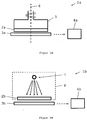
- Figure 1A a structure of an optoelectronic angle sensor 1a is sketched for determining a rotation angle about an axis.
- An around the axis 6 - axis of rotation - arranged disc 2a as a code carrier is inserted into a skirt 5.
- the enclosure 5 is connected to a tool or a motor.
- the enclosure 5 can also be inserted into the alhidade of a theodolite and rotate with it.
- the circular disc 2a rotates - as indicated by the arrow - with respect to an electro-optical detector 3a, which is arranged relative to the circular disc 2a such that on the detector 3a facing surface of the circular disc 2a applied code elements are imaged on the detector 3a.
- Circular disk 2a and detector 3a are coaxial here centered.
- the image - or the angle-proportional measurement signals - is further processed in an electronic component 4a as a memory and evaluation component.
- an electronic reference pattern which can be variably parametrically varied by a parameter, is stored in the electronic component 4a, which is compared with the measurement signals. Based on a parameter estimate, the angle of rotation about the axis 6 is determined.
- FIG. 1B shows an angle sensor 1b with a relative to a detector 3b rotatable disc 2b and a radiation source 7 of an imaging device.
- the detector 3b is substantially the same size as the circular disc 2b.
- Radiation source 7 and disc 2b are arranged in a common - shown by dashed lines - housing 8, so that the radiation source 7 and disc 2b rotate together.
- the radiation source 7 can also be arranged outside the rotating parts and be stationary.
- the detector 3b may be formed and arranged as a rotating component.
- the circular disc 2b is made of optically transparent material, such as glass or plastic, and has - not shown - for the radiation transmissive and impermeable areas as coding.
- a memory and evaluation component 4b For example, an FPGA (field-programmable gate array), compared with an electronic reference pattern and determined in the comparison process of the rotation angle.
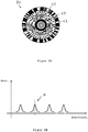
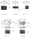
- FIG. 2A an embodiment of a circular disc 2c of an inventive optoelectronic angle sensor is shown.
- the circular disc 2c carries a largely full-surface coding, which here has a first, second and third sub-code.
- the first subcode is an azimuthally extended binary absolute code c1 applied in the outer area of the circular disk 2c.
- the second subcode is executed as a polar distributed point code c2.
- the concentric circles c3 around the circular disc center form the third subcode.
- the circular disc 2c shown enables the determination of the rotation angle by means of the following steps:
- the coding is imaged on the detector so that the first, second and third partial codes are largely completely - for example 95% - detected. From the image of the absolute code c1, a coarse value of the rotation angle can be determined.
- the measurement signals representing the image of the point code c2 are algorithmically compared with the idealized data of an imaging model of the point code c2 forming the reference pattern on the basis of a correlation formation.
- the point code c2 on the circular disc 2c is an ambiguous code, so provides no unique position information.
- the correlation of the idealized data with the measurement signals results in several correlation peaks, as in the representation of the correlation of the data as a function of the rotation angle FIG. 2B shown.
- the relevant angular interval and the correct correlation peak p selected.
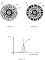
- the FIG. 3A shows a circular disc 2d with two sub-codes as coding, the rotation angle is basically determined from the image and the evaluation of the polar distributed point code c4 as a partial code.
- the illustrated further sub-code - the azimuthally extended radial code c3 '- is provided for eliminating eccentricity and Achstaumelschreibn.
- the circumferentially and radially extending, polar distributed point code c4 carries a unique position information.
- the desired rotation angle is determined as the angle of rotation associated with the maximum correlation value.
- the circular disk 2e in FIG. 3B has one for coding FIG. 2B similar full-surface coding on.
- the dot code c4 'of the middle code track is like the dot code off FIG. 3A , clearly.
- the absolute code c2 'of the outer code track is provided to obtain an initial value for the software-performed correlation formation of the point code c4' with a reference pattern. This accelerates the formation of the correlation and reduces the required computer power.
- an angle value determined from the absolute code c2 ' may be used as an initial value in an angle-dependent function representing the reference pattern and varied until the correlation reaches a maximum or a predetermined correlation value.
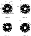
- 4A is an absolutely coded circular disk 2f of an angle sensor with a, applied substantially over the entire disk surface, binary code c5 shown in a coordinate system in the 0 ° -angle position.
- the binary code c5 is formed of translucent and opaque code elements and varies depending on the angle in both the azimuthal and radial directions.
- the representation of the binary code c5 is purely exemplary.
- the circular disc 2f is miniaturized. By virtue of the fact that the binary code c5 is applied essentially over the entire surface, a high number of transitions-and thus coding with a high information content-can nevertheless be achieved. Since the circular disc 2f is miniaturized, an economical embodiment of an angle sensor with a detector whose surface corresponds approximately to the surface of the circular disc can be realized.
- FIG. 4B shows the circular disc 2f after a rotation by about 45 °.
- the position of a flat photosensitive detector of the angle sensor is also shown with dashed lines.
- a largely complete evaluable image of the coding can be generated on the detector.
- an evaluation method is used for angle determination, which makes it possible to evaluate the imaged code structures.
- the evaluation method here comprises the provision of a electronic reference pattern, which describes a statistical distribution of a random variable - in this case the rotation angle - the description is based on an estimator.
- the measurement function - the image - and the estimation function are compared with each other, whereby the random variable - the rotation angle - is systematically changed.
- the comparison or the estimate provides a best estimator for the angle of rotation.
- FIG. 4C represents the area of the binary code c5 which is imaged as an image on the detector.
- Figure 4D shows a pictorial, purely illustrative, representation of a reference pattern, which duplicates the binary code c5.
- the reference pattern is a replica c5 'of the binary code c5 at the 0 ° position - reference position - off FIG. 4A drawn.
- the actual replication takes place by means of an appropriate software.
- FIG. 5A corresponds to the detecting surface of the detector 3g approximately the surface of the circular disc 2g, so that substantially the entire applied to the disc 2g coding can be mapped in a simple manner to the detector 3g.
- the detector 2g is eg a 1000 x 1000 CMOS pixel sensor.
- the axis of rotation 6 'of the angle sensor coincides with the geometric axes of circular disk 2g and detector 3g - circular disk 2g and detector 3g are arranged coaxially centered. This is also in FIG. 5B the case.
- FIG. 5C shows an embodiment with a detector 3i whose center does not coincide with the axis of rotation of the angle sensor.
- the means for imaging and the storage and evaluation component of the angle sensor are not shown.
- the device for generating the image is designed and arranged such that the largest possible, in particular the entire, region of the coding of the circular disk is imaged on the detector elements.
- the image corresponds to electrical measurement signals which are compared pixel by pixel, for example, with ideal data derived from an imaging model of the coding or the image or, as described above, in an alternative manner with an alternative electronic reference pattern.
- the Figures 6A-6D are illustrations of an angle sensor with different means for generating an evaluable image of the circular disc encoding.
- the mapping of the coding can basically from the outside or inside in incident or transmitted light, or by a self-luminous code. Shown is only the lighting from the outside.
- the illumination is transmitted light: the radiation of two photodiodes 10a and 10b or 10a 'and 10b' is projected onto the circular disk 2j or 2j 'and to the detector 3j or by means of an optical unit exemplified here as a lens 11 or 11'. 3j 'shown.
- the radiation of the photodiodes 10a and 10b or 10a' and 10b ' is widened, in FIG. 6A by means of a scattering deflecting mirror 12 and in FIG. 6B through a scattering medium 13.
- the Figures 6C and 6D show the illumination of the disc in incident light.
- the radiation emitted by a radiation source 14 is irradiated in FIG. 6C directed by a beam splitter 15 on the circular disc 2k.
- the radiation reflected at the circular disk 2k passes through the beam splitter 15 via an imaging optical system 16 onto the detector 3k.
- the illumination takes place at an oblique incidence of the light of the radiation source 14 'on the circular disc 2k'.
- the reflected light is in turn directed to the detector 3k 'via imaging optics 16'.
- the imaging optics can each be formed from lenses with conical and / or spherical and / or aspherical surfaces.
Landscapes
- Physics & Mathematics (AREA)
- General Physics & Mathematics (AREA)
- Optical Transform (AREA)
- Length Measuring Devices By Optical Means (AREA)
- Light Receiving Elements (AREA)
Description
Die Erfindung betrifft einen optoelektronischen Winkelsensor nach dem Oberbegriff des Anspruchs 1 sowie ein Verfahren zum Bestimmen eines Drehwinkels um eine Achse nach Anspruch 10.The invention relates to an optoelectronic angle sensor according to the preamble of
Wie in vielen anderen Bereichen werden auch im Bereich der optoelektronischen Winkelsensoren immer kleinere Bauformen angestrebt. Übliche optoelektronische Winkelsensoren zum Bestimmen eines Drehwinkels um eine Achse weisen einen Codeträger und einen optischen Detektor auf, die relativ zueinander drehbar sind. Der optische Detektor ist beispielsweise ein Photodetektor, ein CCD-Zeilen-Array oder ein CCD-Flächen-Array. Der Codeträger ist im Allgemeinen als Kreisscheibe oder als Kreisring ausgebildet und trägt entlang seines Umfangs einen optisch erfassbaren Positionscode, von dem ein Ausschnitt auf den Detektor abgebildet wird.As in many other areas, smaller and smaller designs are also being sought in the field of optoelectronic angle sensors. Conventional optoelectronic angle sensors for determining a rotation angle about an axis comprise a code carrier and an optical detector, which are rotatable relative to each other. The optical detector is, for example, a photodetector, a CCD line array or a CCD area array. The code carrier is generally designed as a circular disk or as a circular ring and carries along its circumference an optically detectable position code, of which a section is imaged onto the detector.
In seinen Abmessungen ist im Allgemeinen der Detektor wesentlich kleiner als der Codeträger. Zur Miniaturisierung des Winkelsensors ist daher in erster Linie eine Verkleinerung des Codeträgers erforderlich. Mit einem Codeträger mit verringertem Durchmesser kann das Verhältnis von Detektor-Fläche zu Codeträger-Fläche erhöht und so ein grösserer Bereich des auf dem Codeträger aufgebrachten Codes erfasst werden. Zusätzlich ist für einen Winkelsensor mit dem Codeträger als drehender Komponente und dem Detektor als feststehender Komponente eine höhere Betriebsstabilität erreichbar, da sich die auf den Codeträger wirkenden Zentrifugalkräfte verringern. Im Allgemeinen dreht sich der Codeträger des Winkelsensors. Es ist jedoch ebenso möglich, den Codeträger feststehend und den Detektor drehend auszubilden.In terms of dimensions, the detector is generally much smaller than the code carrier. To miniaturize the angle sensor therefore a reduction of the code carrier is required in the first place. With a code carrier with a reduced diameter, the ratio of detector area to code carrier area can be increased and thus a larger area of the code applied to the code carrier can be detected. In addition, for an angle sensor with the code carrier as a rotating component and the detector as a fixed component, a higher operating stability can be achieved because of the on the Reduce code carrier acting centrifugal forces. In general, the code carrier of the angle sensor rotates. However, it is also possible to fix the code carrier and make the detector rotating.
Bei der Miniaturisierung des Winkelsensors stellt sich nun das Problem, dass eine Verkleinerung der Codeträger-Fläche auch eine Verkleinerung und/oder Verfeinerung der Code-Strukturen erfordert. Die Codierung kann jedoch insofern nicht beliebig verfeinert werden, als mit immer feineren Strukturen immer grössere Beugungseffekte auftreten und die Strukturen nicht mehr mit der erforderlichen Genauigkeit aufgelöst werden können. Die Winkelauflösung wird durch die Auflösung der Codierung mittels des Detektors bestimmt und hängt damit vom Auflösevermögen des Detektors ab. Dieses ist jedoch beschränkt, da eine Verkleinerung der Pixelgrösse durch das Signal-zu-Rausch-Verhältnis limitiert ist. Alternativ ist eine höhere Winkelauflösung durch Vergrösserung des Durchmessers des Codeträgers erreichbar, was jedoch im Widerspruch zu allen Miniaturisierungsbestrebungen steht.In the miniaturization of the angle sensor, the problem now arises that a reduction of the code carrier surface also requires a reduction and / or refinement of the code structures. However, the coding can not be arbitrarily refined insofar as ever finer structures ever greater diffraction effects occur and the structures can not be resolved with the required accuracy. The angular resolution is determined by the resolution of the coding by means of the detector and thus depends on the resolving power of the detector. However, this is limited because a reduction of the pixel size is limited by the signal-to-noise ratio. Alternatively, a higher angular resolution can be achieved by increasing the diameter of the code carrier, which is in contradiction to all Miniaturisierungsbestrebungen.
Im Stand der Technik werden Winkelsensor-Bauformen verkleinert, indem optische oder mechanische Komponenten reduziert werden. Es ist jedoch keine Lösung bekannt, einen Winkelsensor mittels Verkleinerung seiner codetragenden Fläche zu miniaturisieren, ohne an Winkelauflösung und damit Messgenauigkeit zu verlieren bzw. die Winkelauflösung bei gleichbleibender Grösse des Codeträgers zu erhöhen.In the prior art, angle sensor designs are downsized by reducing optical or mechanical components. However, there is no known solution to miniaturize an angle sensor by reducing its code-carrying surface, without losing angle resolution and thus measurement accuracy or to increase the angular resolution at a constant size of the code carrier.
Die
Diese mechanische Lösung ermöglicht jedoch lediglich die Verkleinerung der Teilscheibe um die äussere Einfassung und bietet daher nur Spielraum für eine Verkleinerung des Winkelsensors im Bereich einiger Prozent. Sie stellt keine Möglichkeit bereit, den Durchmesser der codetragenden Fläche des Sensors wesentlich, beispielsweise um 80%, zu reduzieren und den Winkelsensor damit zu miniaturisieren.However, this mechanical solution allows only the reduction of the part of disc around the outer enclosure and therefore offers only scope for a reduction of the angle sensor in the range of a few percent. It does not provide any possibility to substantially reduce the diameter of the code-bearing surface of the sensor, for example by 80%, and thus to miniaturize the angle sensor.
Das Dokument
Es ist eine Aufgabe der Erfindung, einen optoelektronischen Winkelsensor bereitzustellen, mit welchem Winkelsensor auch mit einem im Durchmesser reduzierten Codeträger eine genaue Bestimmung des Drehwinkels möglich ist.It is an object of the invention to provide an optoelectronic angle sensor, with which angle sensor, even with a reduced in diameter code carrier an accurate determination of the rotation angle is possible.
Eine weitere Aufgabe der Erfindung ist die Bereitstellung eines in Bezug auf die Genauigkeit der Winkelbestimmung verbesserten optoelektronischen Winkelsensors.Another object of the invention is to provide an opto-electronic angle sensor improved in terms of accuracy of angle determination.
Ebenfalls eine Aufgabe der Erfindung ist es, einen hinsichtlich der Flächennutzung des Codeträgers verbesserten optoelektronischen Winkelsensor bereitzustellen.It is likewise an object of the invention to provide an optoelectronic angle sensor improved with regard to the area utilization of the code carrier.
Eine weitere Aufgabe ist es, ein Verfahren zur Bestimmung eines Drehwinkels bereitzustellen, welches die Drehwinkelbestimmung mit einem Codeträger mit reduziertem Durchmesser ermöglicht.A further object is to provide a method for determining a rotation angle, which enables the rotation angle determination with a code carrier with a reduced diameter.
Eine weitere Aufgabe ist die Bereitstellung eines Verfahrens zur Bestimmung eines Drehwinkels mit verbesserter Genauigkeit.Another object is to provide a method for determining a rotation angle with improved accuracy.
Diese Aufgaben werden durch die Gegenstände der Ansprüche 1, 10 oder der abhängigen Ansprüche gelöst bzw. die Lösungen weitergebildet.These objects are achieved by the subject-matters of
Die Erfindung beruht darauf, dass die Codierung der Kreisscheibe eines erfindungsgemässen optoelektronischen Winkelsensors weitgehend vollständig als Bild erfasst und die erfassten Bilder - respektive die Detektor-Messsignale - als Realisationen eines statistischen Parameters interpretiert werden. Zur Auswertung der Messsignale wird aus einer konstruierten Verteilung von Parameterwerten der die Messsignale charakterisierende Parameterwert ermittelt.The invention is based on the fact that the coding of the circular disk of an optoelectronic angle sensor according to the invention is largely completely captured as an image and the captured images-or the detector measurement signals-are interpreted as realizations of a statistical parameter. To evaluate the measurement signals, the parameter value characterizing the measurement signals is determined from a constructed distribution of parameter values.
Hierzu wird mittels einer Einrichtung des Winkelsensors ein weitgehend vollständiges, insbesondere gesamthaftes, auswertbares Bild der Codierung der Kreisscheibe auf dem Detektor des Winkelsensors erzeugt. Beispielsweise werden 90% der Codierung als Bild erfasst. Das Bild beinhaltet eine Information über die Relativposition von Kreisscheibe und Detektor, die relativ zueinander bewegbar sind. Die Relativbewegung umfasst zumindest eine Relativ-Drehbewegung um eine Achse. Zusätzlich können Kreisscheibe und Detektor auch - äusserst kleine - translatorische Relativbewegungen und/oder Taumelbewegungen, die z.B. aus Montage- und/oder Fertigungsungenauigkeiten resultieren, ausführen.For this purpose, by means of a device of the angle sensor, a substantially complete, in particular overall, evaluatable image of the coding of the circular disk is generated on the detector of the angle sensor. For example, 90% of the encoding is captured as an image. The image includes information about the relative position of the circular disc and the detector, which are movable relative to each other. The relative movement comprises at least one relative rotational movement about an axis. In addition, the circular disk and the detector can also detect extremely small translatory relative movements and / or tumbling movements, which are e.g. resulting from assembly and / or manufacturing inaccuracies, perform.
Unter auswertbarem Bild ist in diesem Zusammenhang ein Bild, aus welchem die Information über die Relativposition ermittelt werden kann, zu verstehen. Das Bild muss dabei nicht notwendigerweise eine scharfe Abbildung der Codierung darstellen. Im Rahmen der Beschreibung der Erfindung werden für das auswertbare Bild auch die Begriffe Abbildung, Projektion, Messsignale oder Messmuster verwendet.Under evaluable image in this context, an image from which the information about the relative position can be determined to understand. The picture has to be there not necessarily represent a sharp picture of the coding. Within the scope of the description of the invention, the terms image, projection, measuring signals or measuring patterns are also used for the evaluable image.
Die Codierung der Kreisscheibe eines erfindungsgemässen Winkelsensors ist derart ausgeführt, dass im Wesentlichen die gesamte Fläche der Scheibe genutzt wird. Dies wird realisiert, indem der weitgehend gesamte Flächenbereich der Scheibe mit Code versehen wird. Insbesondere weist die auf die Kreisscheibe aufgebrachte Codierung einen Code auf, der sich sowohl in azimutaler als auch radialer Richtung erstreckt und sich in beiden Richtungen winkelabhängig verändert. Z. B. wird ein üblicher Code, der auf einer üblichen Kreisscheibe im äusserem Bereich der Kreisscheibe entlang deren Umfangs aufgebracht ist und sich in Umfangsrichtung winkelabhängig verändert, sowohl in Umfangsrichtung als auch quer dazu auf die Kreisscheibe des erfindungsgemässen Winkelsensors aufgebracht, beispielsweise mäanderförmig - der Code wird sozusagen auf die Scheibe "gefaltet". Damit trägt der Code entgegen dem üblichen Code zusätzlich auch in radialer Richtung winkelabhängige Code-Information.The coding of the circular disc of an inventive angle sensor is designed such that substantially the entire surface of the disc is used. This is realized by providing the largely entire area of the disc with code. In particular, the code applied to the circular disk has a code which extends in both an azimuthal and a radial direction and changes in an angle-dependent manner in both directions. For example, a common code, which is applied on a conventional circular disc in the outer region of the circular disc along the circumference and changes angularly in the circumferential direction, both circumferentially and transversely applied to the circular disc of the inventive angle sensor, for example, meandering - the code is so to speak "folded" on the disc. Thus, the code carries in addition to the usual code in addition also in the radial direction angle-dependent code information.
Der Informationsgehalt der Codierung wird durch die Anzahl der Übergänge - auch als "Nervosität" des Codes bezeichnet - bestimmt. Die Übergänge werden durch die Wechsel der Eigenschaften der Codeelemente, wie LichtDurchlässigkeit/Licht-Undurchlässigkeit oder Reflexion/ Absorption, erzeugt. Durch die weitgehend vollflächige Aufbringung der Codierung und damit Nutzung im Wesentlichen der gesamten Fläche der Kreisscheibe wird eine maximierte Zahl von Übergängen erhalten.The information content of the coding is determined by the number of transitions - also called "nervousness" of the code. The transitions are created by changing the characteristics of the code elements, such as light transmission / opacity or reflection / absorption. Due to the largely full-surface application of the coding and thus utilization of substantially the entire surface of the circular disk, a maximized number of transitions is obtained.
Die solcherart codierte Kreisscheibe entspricht sozusagen einer "codierten Achse". Anhand dieser Codierung ist auch auf eine im Durchmesser verkleinerte Kreisscheibe eine grosse Anzahl von Übergängen zur gattungsgemäss genauen Winkelbestimmung aufbringbar. Mit einer räumlich verdichteten Aufbringung der Codierung kann der Durchmesser der Kreisscheibe wesentlich, beispielsweise um über 90% gegenüber üblichen in Theodoliten eingesetzten Glas- oder Kunststoff-Kreisscheiben mit einem Durchmesser von ca. 78 mm, verringert werden. Beispielsweise ist die Kreisscheibe als "Minischeibe" mit einem Durchmesser zwischen 6 mm und 10 mm ausführbar. Eine solche Verkleinerung der Kreisscheibe ermöglicht eine starke Reduzierung der Abmessungen des Winkelsensors als Ganzes und damit die Realisierung eines miniaturisierten Winkelsensors.The thus coded disc corresponds to a so-called "coded axis". On the basis of this coding, a large number of transitions to the exactly exact angle determination can also be applied to a circular disc reduced in diameter. With a spatially compacted application of the coding, the diameter of the circular disk can be significantly reduced, for example, by more than 90% compared to conventional glass or plastic circular disks with a diameter of about 78 mm used in theodolites. For example, the circular disc as "mini disc" with a diameter between 6 mm and 10 mm executable. Such a reduction of the circular disc allows a large reduction in the dimensions of the angle sensor as a whole and thus the realization of a miniaturized angle sensor.
Wird die Kreisscheibe bzw. der Winkelsensor nicht verkleinert, so kann mit einer entsprechenden Ausbildung der Kreisscheibe ein Winkelsensor zur Winkelbestimmung mit verbesserter Genauigkeit verwirklicht werden.If the circular disk or the angle sensor is not reduced, an angle sensor for angle determination with improved accuracy can be realized with a corresponding design of the circular disk.
In einer Weiterbildung der Erfindung umfasst die Codierung der Kreisscheibe mehrere Teilcodes. Der vorgängig erwähnte, azimutal und radial ausgedehnte Code kann z.B. einen Teilcode bilden. Zusätzlich kann ein Teilcode als entlang des Umfangs, z.B. im äusseren Bereich der Kreisscheibe, aufgebrachter Absolutcode vorgesehen sein, dessen Erfassung einen Grobwert des Drehwinkels liefert, der eine Verbesserung der Drehwinkel-Bestimmung in Bezug auf die Geschwindigkeit des Auswertealgorithmus ermöglicht.In a development of the invention, the coding of the circular disk comprises a plurality of partial codes. The previously mentioned, azimuthally and radially expanded code can form, for example, a subcode. In addition, a partial code can be provided as an absolute code applied along the circumference, for example in the outer region of the circular disc, the detection of which provides a coarse value of the angle of rotation which makes it possible to improve the rotational angle determination with respect to the speed of the evaluation algorithm.
Ein weiterer Teilcode kann als zusätzlicher Code zur Erfassung translatorischer Bewegungen der Kreisscheibe ausgebildet sein, beispielsweise als azimutal erstreckter Radialcode, wie in Form konzentrischer Kreise um den Mittelpunkt der Kreisscheibe, also im inneren Bereich derselben. Durch Auslesen einzelner Detektor-Zeilen in azimutaler und radialer Richtung, ist aus dem Bild des Radialcodes eine schnelle absolute Achstaumelbestimmung möglich. Indem der Teilcode für translatorische Bewegungen in einem inneren Segment der Kreisscheibe aufgebracht ist, wird auch diese innere Fläche, die für die Bestimmung des Drehwinkels wenig geeignet ist, sinnvoll genutzt.A further subcode can be embodied as an additional code for detecting translational movements of the circular disk, for example as an azimuthally extended radial code, such as in the form of concentric circles around the center of the circular disk, ie in the inner region thereof. By reading out individual detector lines in the azimuthal and radial directions, the image of the radial code makes possible a fast absolute axis wobble determination. By the sub-code for translational movements is applied in an inner segment of the circular disc, and this inner surface, which is not very suitable for the determination of the rotation angle, used meaningfully.
Um von der Codierung das Bild zu erzeugen, ist eine Einrichtung zum Abbilden respektive Projizieren der Codierung auf den Detektor des Winkelsensors vorgesehen. Die Einrichtung, die Kreisscheibe und der Detektor des erfindungsgemässen Winkelsensors sind derart ausgebildet und angeordnet, dass die Codierung weitgehend vollständig, insbesondere gesamthaft, auf den Detektor abgebildet wird. Vorzugsweise wird ein Bild respektive Messmuster erstellt, welches wenigstens 50%, insbesondere mehr als 75% und vorteilhaft 100% der Codierung aufweist.In order to generate the image from the coding, means are provided for mapping or projecting the coding onto the detector of the angle sensor. The device, the circular disk and the detector of the inventive angle sensor are designed and arranged such that the coding is largely completely, in particular total, imaged on the detector. Preferably, an image or measurement pattern is created which has at least 50%, in particular more than 75% and advantageously 100% of the coding.
Die weitgehend vollständige Erfassung mit zur Auswertung ausreichender Auflösung der Codierung kann anhand eines entsprechenden Beleuchtungskonzepts, einer verkleinerten Kreisscheibe, der Ausbildung und Anordnung von Einrichtung, Kreisscheibe und Detektor bzw. anhand einer Kombination des genannten verwirklicht werden.The largely complete detection with sufficient resolution of the coding can be realized on the basis of a corresponding lighting concept, a reduced circular disk, the design and arrangement of equipment, disk and detector or by a combination of the above.
Zum Erzeugen des Bildes umfasst die Einrichtung eine Strahlungsquelle, wie eine oder mehrere Photodioden zum Beleuchten der Kreisscheibe. Je nach Ausbildung der Codierung - z.B. mit lichtdurchlässigen und lichtundurchlässigen oder durch unterschiedliches Reflexionsvermögen unterscheidbaren Code-Elementen - erfolgt die Bilderzeugung in Durchlicht oder Auflicht. Beim Durchlicht-Verfahren empfängt der Detektor die durchgelassene, durch die Code-Elemente modulierte Strahlung, beim Auflicht-Verfahren die reflektierte, durch die Code-Elemente modulierte Strahlung.For generating the image, the device comprises a radiation source, such as one or more photodiodes for Illuminate the circular disk. Depending on the design of the coding - for example with translucent and opaque or distinguishable by different reflectivity code elements - the image is generated in transmitted or reflected light. In the transmitted-light method, the detector receives the transmitted radiation modulated by the code elements, in reflected-light mode the reflected radiation modulated by the code elements.
Eine möglichst homogene Ausleuchtung der Kreisscheibe bzw. eines Kreisscheiben-Bereichs ist durch Strahl-Aufweitung mittels einer entsprechenden Optik, die beispielsweise durch einen Umlenkspiegel oder ein streuendes Medium gebildet sein kann, realisierbar. Die Einrichtung ist insbesondere zum Projizieren eines Bereichs der Kreisscheibe, der dem Bereich der Detektorelemente entspricht, ausgelegt. Gegebenenfalls kann die Einrichtung auch einen selbstleuchtenden Code, z.B. mit organischen Leuchtdioden, darstellen.A possible homogeneous illumination of the circular disk or a circular disk area can be realized by beam expansion by means of a corresponding optical system, which may be formed for example by a deflecting mirror or a scattering medium. The device is designed in particular for projecting a region of the circular disc which corresponds to the region of the detector elements. Optionally, the device may also include a self-luminous code, e.g. with organic light emitting diodes, represent.
Die Kreisscheibe kann - wie vorgängig erwähnt - vorteilhaft verkleinert werden. Dies ermöglicht eine - wirtschaftliche - Ausführungsform eines erfindungsgemässen Winkelsensors mit einem Detektor, dessen Fläche im Wesentlichen der Fläche der Kreisscheibe entspricht. Insbesondere ist ein Detektor einsetzbar, dessen Längen- und Breitenabmessungen dem Durchmesser der Kreisscheibe entsprechen. Eine solche Ausführungsform, in welcher die codetragende Kreisscheibe und der Detektor weitgehend gleich dimensioniert sind, ermöglicht auf einfache Art und Weise die Erfassung der im Wesentlichen gesamten Kreisscheiben-Fläche respektive der darauf aufgebrachten Codierung auf dem Detektor. Zusätzlich kann damit vorteilhaft eine Beabstandung des Kreisscheiben-Zentrums von der Drehachse - eine Exzentrizität festgestellt werden. In einer Ausführungsform der Erfindung sind die Kreisscheibe und der Detektor weitgehend deckungsgleich und koaxial zentriert angeordnet.The circular disk can - as mentioned above - be advantageously reduced in size. This enables an economic embodiment of an angle sensor according to the invention with a detector whose area substantially corresponds to the area of the circular disk. In particular, a detector can be used whose length and width dimensions correspond to the diameter of the circular disk. Such an embodiment, in which the code-carrying disc and the detector are dimensioned substantially equal, allows the detection of the substantially entire circular disc surface respectively the applied thereon coding on the detector in a simple manner. additionally can thus advantageously a spacing of the circular disk center of the axis of rotation - an eccentricity can be determined. In one embodiment of the invention, the circular disk and the detector are arranged largely congruent and coaxially centered.
Der Detektor stellt einen, z.B. durch Anordnungen von CCD-Zeilen-Arrays und CCD-Spalten-Arrays gebildeten, flächigen photosensitiven Detektor dar. Eine matrizenförmige Anordnung photosensitiver Bereiche ist mit einem CCD-Flächensensor oder CMOS-Flächensensor realisierbar. Ebenso können alternative übliche Sensoren eingesetzt werden.The detector provides a, e.g. A planar photosensitive detector formed by arrangements of CCD line arrays and CCD column arrays. A matrix-like arrangement of photosensitive areas can be realized with a CCD area sensor or CMOS area sensor. Likewise, alternative conventional sensors can be used.
Das Bild respektive die Messsignale des Detektors beinhalten Informationen über die Relativposition von Kreisscheibe und Detektor, welche Informationen durch einen Vergleich mit einem elektronischen Referenzmuster unter Anwendung eines parametervariierenden Vergleichsverfahrens ausgewertet werden. Anhand dieser Auswertung können auch sehr kleine und feine Code-Strukturen noch mit hoher Genauigkeit aufgelöst und der Drehwinkel genau bestimmt werden.The image or the measurement signals of the detector contain information about the relative position of the circular disc and the detector, which information is evaluated by comparison with an electronic reference pattern using a parameter-varying comparison method. On the basis of this evaluation even very small and fine code structures can be resolved with high accuracy and the rotation angle can be determined exactly.
Das elektronische Referenzmuster wird mittels einer Speicher- und Auswertekomponente des erfindungsgemässen Winkelsensors bereitgestellt. Die Speicher- und Auswertekomponente ist weiters zum Auswerten der Detektor-Messsignale anhand des erwähnten Auswerteverfahrens ausgebildet. Dazu weist die Speicher- und Auswertekomponente ein Computerprogrammprodukt auf, welches Programmcode enthält, der so angepasst ist, dass er das Verfahren ausführt, wenn er auf der Komponente abläuft. Zum Auswerten der Bildinformation, die z.B. als elektrische digitale Detektor-Signale vorliegt, insbesondere zum numerischen Bearbeiten einer grossen Datenmenge, wie z.B. der Datenmenge eines 1000 x 1000 CMOS-Pixelsensors, ist die Speicher- und Auswertekomponente z.B. als Mikroprozessor ausgebildet. Auch ein FPGA (field-programmable gate array) oder ein ASIC (Application Specific Integrated Circuit) ist als Speicher- und Auswertekomponente geeignet.The electronic reference pattern is provided by means of a memory and evaluation component of the inventive angle sensor. The memory and evaluation component is further designed for evaluating the detector measurement signals on the basis of the aforementioned evaluation method. For this purpose, the storage and evaluation component has a computer program product which contains program code which is adapted to execute the method as it runs on the component. To evaluate the image information, eg as electrical digital detector signals is present, in particular for the numerical processing of a large amount of data, such as the amount of data of a 1000 x 1000 CMOS pixel sensor, the memory and evaluation component is designed for example as a microprocessor. An FPGA (Field Programmable Gate Array) or an ASIC (Application Specific Integrated Circuit) is also suitable as a memory and evaluation component.
Das Referenzmuster ist als statistische Verteilung für eine unbekannte charakteristische Grösse der Winkelbestimmung respektive der Detektor-Messsignale modellierbar. Beispielsweise stellt das Referenzmuster eine Schätzfunktion der Grösse dar. Die charakteristische Grösse kann der Drehwinkel sein. Die unbekannte Grösse des statistischen Modells ist anhand statistischer Methoden, wie Schätzmethoden, ermittelbar.The reference pattern can be modeled as a statistical distribution for an unknown characteristic quantity of the angle determination or the detector measurement signals. For example, the reference pattern represents an estimation function of the size. The characteristic variable may be the angle of rotation. The unknown size of the statistical model can be determined using statistical methods, such as estimation methods.
Das Referenzmuster kann auch durch einen Algorithmus, der das Messmuster respektive das Bild respektive die Detektor-Messsignale und/oder die Codierung simuliert oder dupliziert, gebildet sein. Z. B. werden für eine möglichst realistische Beschreibung des Messmusters die Codestruktur, die Abbildungsparameter der Einrichtung und des Detektors, sowie Abbildungsfehler berücksichtigt.The reference pattern can also be formed by an algorithm which simulates or duplicates the measurement pattern or the image respectively the detector measurement signals and / or the coding. For example, for a most realistic description of the measurement pattern, the code structure, the imaging parameters of the device and the detector, and aberrations are taken into account.
In einer Ausführungsform der Erfindung wird als stochastische Vergleichsmethode zum Auswerten des Messmusters die Maximum-Likelihood-Methode angewandt. Das erfindungsgemässe Verfahren weist dann z.B. die folgenden Schritte auf:
- o Erzeugen eines Messmusters,
- o Erzeugen eines das Messmuster möglichst realistisch beschreibenden Referenzmusters als Funktion eines Parameters,
- o Vergleichen des Messmusters mit dem Referenzmuster,
- o Variieren des Parameters bis das Referenzmuster die maximale bzw. maximal erreichbare Ähnlichkeit zum Messmuster zeigt,
- o Festlegen des Parameters als besten Schätzer und Bestimmen des Drehwinkels aus der Parameterschätzung.
- o generating a measuring pattern,
- o generating a reference pattern that describes the measurement pattern as realistically as possible as a function of a parameter,
- o comparing the measuring pattern with the reference pattern,
- o varying the parameter until the reference pattern shows the maximum or maximum achievable similarity to the measurement pattern,
- o Set the parameter as the best estimator and determine the rotation angle from the parameter estimate.
Der Parameter stellt beispielsweise einen Referenz-Drehwinkel, der den Drehwinkel respektive die relative rotatorische Lage von Kreisscheibe und Detektor beschreibt, dar. Aus der Parameterschätzung erhält man den Wert für den Referenz-Drehwinkel, der mit der grössten Wahrscheinlichkeit das Messmuster hervorbringen würde.The parameter represents, for example, a reference rotation angle which describes the rotation angle or the relative rotational position of the circular disk and the detector. The parameter estimate yields the value for the reference rotation angle which would most likely produce the measurement pattern.
In einer weiteren Ausführungsform der Erfindung wird das Messmuster anhand einer, auf einem integralen Vergleich des Messmusters mit dem parametrisierten elektronischen Referenzmuster beruhenden, mathematischen Korrelationsmethode ausgewertet. Der Parameter stellt einen Korrelationsfaktor, der ein Mass für die Übereinstimmung von Mess- und Referenzmuster ist, dar. Im Rahmen der Korrelation wird der Parameter solange variiert, bis eine vorgegebene Korrelationsbedingung - z.B. ein maximaler oder minimaler Korrelationswert - erreicht ist.In a further embodiment of the invention, the measurement pattern is evaluated on the basis of a mathematical correlation method based on an integral comparison of the measurement pattern with the parameterized electronic reference pattern. The parameter represents a correlation factor which is a measure of the match of measurement and reference patterns. In the context of the correlation, the parameter is varied until a predetermined correlation condition - e.g. a maximum or minimum correlation value - is reached.
Beispielsweise wird für eine solche Korrelationsbildung das Messmuster als Faltung der Intensitätsfunktion c des Bildes, der optischen Unschärfefunktion b des Schattenwurfs und der elektrischen Signalantwort d eines Detektor-Pixels betrachtet: Q = c * b * d, wobei * der Faltungsoperator ist. Da die Intensitätsfunktion c auch den zu bestimmenden Drehwinkel α beschreibt, ist die Messmuster-Funktion Q auch eine Funktion des zu bestimmenden Drehwinkels α : Q = Q(α).For example, for such a correlation formation, the measurement pattern is regarded as a convolution of the intensity function c of the image, the optical blur function b of the shadow cast and the electrical signal response d of a detector pixel: Q = c * b * d, where * the convolution operator is. Since the intensity function c also describes the rotation angle α to be determined, the measurement pattern function Q is also a function of the rotation angle α to be determined: Q = Q (α).
Das Referenzmuster wird als das Messmuster beschreibende Musterfunktion eines Referenz-Drehwinkels α', der den Drehwinkel beschreibt, erzeugt: P = P(α'). Zur Bestimmung der Positionsinformation des Messmusters werden die Messsignale mit den synthetischen ReferenzSignalen verglichen, wobei als Gütemass die Korrelationsfunktion p = Q(α) ![]()
![]()
![]()
![]()
Beim Vergleichen der Signale wird der Referenz-Drehwinkel α' mathematisch variiert, bis p ein Maximum erreicht - was eine maximale Übereinstimmung der Signale beschreibt. Der Referenz-Drehwinkel α' bei ρ = max. gibt dann den besten Schätzwert des gesuchten Drehwinkels α an. Mit einem derartigen Korrelationsverfahren sind hohe Auflösungswerte - beispielsweise von Pixel/100 - erreichbar.When comparing the signals of the reference rotation angle α 'is mathematically varied until p reaches a maximum - which describes a maximum match of the signals. The reference rotation angle α 'at ρ = max. then gives the best estimate of the desired rotation angle α. With such a correlation method, high resolution values - for example of pixel / 100 - can be achieved.
Zum Vergleichen des Messmusters mit dem Referenzmuster kann auch eine Moire-ähnliche Methode angewandt werden. Das Referenzmuster wird - z.B. modelltheoretisch - als stationäres, mit zur Frequenz eines hochfrequenten Gitters als Codierung leicht verschiedener Hochfrequenz versehenes Gitter bereitgestellt, sodass eine digitale Überlagerung der Gitter zu den bekannten Moire-Strukturen führt. Die Positionsinformation des Messmusters wird anhand eines integralen Vergleichs des Mess- mit dem Referenzmuster ausgewertet. Als Gitterstrukturen sind beispielsweise radiale Gitterstrukturen, wie ein Siemensstern, oder Strukturen wie radiale Fresnelzonengitter - radialer "Chirp" - geeignet.To compare the measurement pattern with the reference pattern, a Moire-like method can also be used. The reference pattern is provided - for example in terms of model theory - as a stationary grating provided with a frequency slightly different from the frequency of a high-frequency grating, so that a digital superimposition of the grids leads to the known moiré structures. The position information of the measuring pattern is evaluated on the basis of an integral comparison of the measuring pattern with the reference pattern. As lattice structures are, for example Radial grating structures, such as a Siemens star, or structures such as radial Fresnelzonengitter - radial "chirp" - suitable.
Je nach Ausführung der Codierung der Kreisscheibe kann das erfindungsgemässe Verfahren zusätzlich weitere Positionsinformationen verwenden. Weist die Codierung einen als Absolutcode ausgeführten Teilcode auf, so kann aus dem Bild des Absolutcodes ein grober Absolutwert für den Drehwinkel bestimmt werden, welcher Grobwert als Anfangswert des Vergleichsverfahrens verwendbar ist. Weiters kann das Verfahren auch die Bildinformationen gewichten, insbesondere radial gewichten. So werden z.B. am äusseren Rand der Kreisscheibe aufgebrachte Codestrukturen, die bezüglich der Information über die relative rotatorische Lage von Kreisscheibe und Detektor besser auswertbar sind als innere Strukturen, im erfindungsgemässen Verfahren für die Auswertung des Drehwinkels stärker gewichtet als weiter innen - zur Drehachse hin - liegende Codestrukturen.Depending on the embodiment of the coding of the circular disk, the method according to the invention can additionally use further position information. If the coding has a partial code embodied as an absolute code, a coarse absolute value for the angle of rotation can be determined from the image of the absolute code, which coarse value can be used as the initial value of the comparison method. Furthermore, the method can also weight the image information, in particular radially. Thus, e.g. Code structures applied on the outer edge of the circular disk, which are more easily evaluated with respect to the information about the relative rotational position of circular disk and detector than internal structures, weighted more heavily in the inventive method for the evaluation of the rotation angle than further inside - to the axis of rotation lying code structures.
Der erfindungsgemässe Winkelsensor und das erfindungsgemässe Verfahren werden nachfolgend anhand von in den Zeichnungen schematisch dargestellten Ausführungsbeispielen rein beispielhaft näher beschrieben oder erläutert. Im Einzelnen zeigen:
- Fig. 1
- zwei Teilfiguren mit Ausführungsformen eines optoelektronischen Winkelsensors;
- Fig. 2
- eine Teilfigur mit einer Ausführungsform einer codierter Kreisscheibe eines Winkelsensors und eine Teilfigur zur Erläuterung des Korrelationsverfahrens;
- Fig. 3
- zwei Teilfiguren mit weiteren Ausführungsformen codierter Kreisscheiben eines Winkelsensors und eine dritte Teilfigur zur Erläuterung des Korrelationsverfahrens;
- Fig. 4
- vier Teilfiguren zur Erläuterung eines erfindungsgemässen Verfahrens zur Bestimmung eines Drehwinkels;
- Fig. 5
- in drei Teilfiguren Anordnungen von Kreisscheibe und Detektor;
- Fig. 6
- vier Teilfiguren mit Einrichtungen eines optoelektronischen Winkelsensors zum Erzeugen des Bildes.
- Fig. 1
- two sub-figures with embodiments of an optoelectronic angle sensor;
- Fig. 2
- a partial figure with an embodiment of a coded circular disc of an angle sensor and a partial figure for explaining the correlation method;
- Fig. 3
- two sub-figures with further embodiments of coded circular disks of an angle sensor and a third sub-figure for explaining the correlation method;
- Fig. 4
- four sub-figures for explaining a method according to the invention for determining a rotation angle;
- Fig. 5
- in three sub-figures arrangements of disc and detector;
- Fig. 6
- four sub-figures with devices of an optoelectronic angle sensor for generating the image.
In
In
Die
Die Kreisscheibe 2e in
Die
In den
Die
In den
Die
Claims (14)
- Optoelectronic angle sensor (1a, 1b) for determining a rotational angle about an axis (6), comprising▪ a circular disc (2a, 2b, 2c, 2d, 2e, 2f, 2g, 2k) rotatable about the axis (6) and having a coding substantially over the whole area,▪ a planar photosensitive detector (3a, 3b, 3g, 3h, 3i, 3j, 3k),
the circular disc (2a, 2b, 2c, 2d, 2e, 2f, 2g, 2k) and the detector (3a, 3b, 3g, 3h, 3i, 3j, 3k) being moveable relative to one another,▪ device for producing an evaluable image of the coding on the detector (3a, 3b, 3g, 3h, 3i, 3j, 3k) in such a way that the image comprises information about the relative position of circular disc (2a, 2b, 2c, 2d, 2e, 2f, 2g, 2k) and detector (3a, 3b, 3g, 3h, 3i, 3j, 3k), and▪ a memory and evaluation component (4a, 4b) for determining the rotational angle,wherein
the device produces a substantially complete, in particular entire, image of the coding and characterized in that
the memory and evaluation component (4a, 4b)▪ provides a configured electronic, in particular model-based, reference pattern which can be coordinated with the coding and▪ determines the rotational angle from reference pattern and image by means of a parameter-varying stochastic comparison method. - Optoelectronic angle sensor (1a, 1b) according to Claim 1, characterized in that the image has at least 50%, in particular more than 75% and preferably 100% of the coding.
- Optoelectronic angle sensor (1a, 1b) according to Claim 1 or 2, characterized in that the areas of detector (3a, 3b, 3g) and circular disc (2a, 2b, 2g) are adapted to one another in their dimensioning, in particular substantially coincide.
- Optoelectronic angle sensor (1a, 1b) according to any of Claims 1 to 3, characterized in that the circular disc (2a, 2b, 2g) and the detector (3a, 3b, 3g, 3h) are arranged so as to be coaxially centred.
- Optoelectronic angle sensor (1a, 1b) according to any of the preceding claims, characterized in that the reference pattern is configured with a reference rotational angle which describes the rotational position of the reference pattern relative to the image.
- Optoelectronic angle sensor (1a, 1b) according to any of the preceding claims, characterized in that the reference pattern is based on▪ a mathematical model of the image or of the coding or▪ a reproducing duplication or simulation of the image or of the coding.
- Optoelectronic angle sensor (1a, 1b) according to any of the preceding claims, characterized in that the comparison method uses a▪ estimation method, in particular maximum likelihood method or least squares method or▪ mathematical correlation method.
- Optoelectronic angle sensor (1a, 1b) according to any of the preceding claims, characterized in that the comparison method has a radial weighting of coding components.
- Optoelectronic angle sensor (1a, 1b) according to any of the preceding claims, characterized in that the coding has a▪ code (c5) variable in an angle-dependent manner both in the azimuthal and in the radial direction and/or▪ incremental code, for example Siemens star, and/or▪ point code (c2, c4) distributed in a polar manner and/or▪ absolute code (c2') and/or▪ azimuthally extending radial code (c3')as a part-code.
- Method for determining a rotational angle about an axis (6), comprising▪ a circular disc (2a, 2b, 2c, 2d, 2e, 2f, 2g, 2k) rotatable about the axis (6) and having a coding substantially over the whole area and▪ a planar photosensitive detector (3a, 3b, 3g, 3h, 3i, 3j, 3k),comprising
the circular disc (2a, 2b, 2c, 2d, 2e, 2f, 2g, 2k) and the detector (3a, 3b, 3g, 3h, 3i 3j, 3k) being moveable relative to one another,▪ production of a substantially complete, in particular entire, evaluable image of the coding on the detector (3a, 3b, 3g, 3h, 3i, 3j, 3k) in a manner such that the image comprises information about the relative position of circular disc (2a, 2b, 2c, 2d, 2e, 2f, 2g, 2k) and detector (3a, 3b, 3g, 3h, 3i, 3j, 3k),▪ provision of an electronic reference pattern which can be varied in configuration by at least one parameter and can be coordinated with the coding,▪ derivation of the rotational angle by comparison of reference pattern and image and by variation of the parameter. - Method according to Claim 10, characterized in that the reference pattern is provided▪ as a mathematical model of the image,▪ as a mathematical model of the coding,▪ as an algorithmic description of the image,▪ as an algorithmic description of the coding,▪ as an image-reproducing simulation or duplication or▪ as a coding-reproducing simulation or duplication.
- Method according to Claim 10 or 11, characterized in that the reference pattern and the image are digitally superposed in the comparison.
- Method according to any of Claims 10 to 12, characterized in that an▪ estimation method, in particular maximum likelihood method or least squares method, or▪ mathematical correlation methodis used in the derivation.
- Method according to any of Claims 10 to 13, characterized in that▪ a reference rotational angle which describes the rotational position of the reference pattern relative to the mapping is chosen as the parameter,▪ a parameter estimation is carried out by the maximum likelihood method and▪ the rotational angle is determined as the estimated parameter.
Priority Applications (1)
| Application Number | Priority Date | Filing Date | Title |
|---|---|---|---|
| EP07786689.5A EP2052216B1 (en) | 2006-08-18 | 2007-08-16 | Optoelectronic angle sensor and method for determining a rotation angle around an axis |
Applications Claiming Priority (3)
| Application Number | Priority Date | Filing Date | Title |
|---|---|---|---|
| EP06119146A EP1890113A1 (en) | 2006-08-18 | 2006-08-18 | Optoelectronic angle sensor and method for determining a rotation angle around an axis |
| PCT/EP2007/007248 WO2008019855A1 (en) | 2006-08-18 | 2007-08-16 | Optoelectronic angle sensor and method for determining a rotational angle about an axis |
| EP07786689.5A EP2052216B1 (en) | 2006-08-18 | 2007-08-16 | Optoelectronic angle sensor and method for determining a rotation angle around an axis |
Publications (2)
| Publication Number | Publication Date |
|---|---|
| EP2052216A1 EP2052216A1 (en) | 2009-04-29 |
| EP2052216B1 true EP2052216B1 (en) | 2016-04-27 |
Family
ID=37600770
Family Applications (3)
| Application Number | Title | Priority Date | Filing Date |
|---|---|---|---|
| EP06119146A Withdrawn EP1890113A1 (en) | 2006-08-18 | 2006-08-18 | Optoelectronic angle sensor and method for determining a rotation angle around an axis |
| EP07786689.5A Active EP2052216B1 (en) | 2006-08-18 | 2007-08-16 | Optoelectronic angle sensor and method for determining a rotation angle around an axis |
| EP07801742.3A Active EP2052218B1 (en) | 2006-08-18 | 2007-08-17 | Optoelectronic angle sensor and method for determining a rotation angle around an axis |
Family Applications Before (1)
| Application Number | Title | Priority Date | Filing Date |
|---|---|---|---|
| EP06119146A Withdrawn EP1890113A1 (en) | 2006-08-18 | 2006-08-18 | Optoelectronic angle sensor and method for determining a rotation angle around an axis |
Family Applications After (1)
| Application Number | Title | Priority Date | Filing Date |
|---|---|---|---|
| EP07801742.3A Active EP2052218B1 (en) | 2006-08-18 | 2007-08-17 | Optoelectronic angle sensor and method for determining a rotation angle around an axis |
Country Status (7)
| Country | Link |
|---|---|
| US (2) | US8462979B2 (en) |
| EP (3) | EP1890113A1 (en) |
| JP (2) | JP5253394B2 (en) |
| CN (2) | CN101506621B (en) |
| AU (2) | AU2007286403B2 (en) |
| CA (2) | CA2660999C (en) |
| WO (2) | WO2008019855A1 (en) |
Families Citing this family (24)
| Publication number | Priority date | Publication date | Assignee | Title |
|---|---|---|---|---|
| JP4989313B2 (en) * | 2007-05-28 | 2012-08-01 | 株式会社トプコン | Absolute angle calculation device |
| CN101952690B (en) * | 2008-02-22 | 2013-02-27 | 特里伯耶拿有限公司 | Angle measuring device and method |
| EP2251647A1 (en) | 2009-05-13 | 2010-11-17 | CSEM Centre Suisse d'Electronique et de Microtechnique SA - Recherche et Développement | Absolute angular position measuring device and method |
| JP5690053B2 (en) * | 2009-06-19 | 2015-03-25 | 株式会社エンプラス | Rotary encoder |
| EP2372302A1 (en) | 2010-03-26 | 2011-10-05 | Leica Geosystems AG | Measuring method for a surface measuring machine |
| EP2498076A1 (en) | 2011-03-11 | 2012-09-12 | Hexagon Technology Center GmbH | Wear-Monitoring of a Gearbox in a Power Station |
| CN102322882A (en) * | 2011-06-02 | 2012-01-18 | 浙江大学 | Absolute shaft angle encoding system based on array detector |
| AT510674B1 (en) * | 2011-10-27 | 2014-05-15 | Avl List Gmbh | METHOD AND DEVICE FOR PARAMETERIZING A SENSOR |
| US9541382B2 (en) | 2011-12-19 | 2017-01-10 | Kabushiki Kaisha Topcon | Rotation angle detecting apparatus and surveying instrument |
| JP6055179B2 (en) * | 2011-12-19 | 2016-12-27 | 株式会社トプコン | Rotation angle detection device and surveying device |
| EP2870433B1 (en) * | 2012-07-04 | 2016-09-07 | Hexagon Technology Center GmbH | Optical positioner with analogue memory |
| EP2682718A1 (en) * | 2012-07-05 | 2014-01-08 | Hexagon Technology Center GmbH | Method for recording an absolute encoding of an optical code track |
| DE102012218890A1 (en) * | 2012-10-17 | 2014-04-17 | Dr. Johannes Heidenhain Gmbh | Absolute position measuring device |
| EP2808653B1 (en) | 2013-05-28 | 2016-07-13 | SICK STEGMANN GmbH | Rotation angle sensor |
| CN103471529B (en) * | 2013-09-26 | 2015-12-02 | 中国科学院长春光学精密机械与物理研究所 | Based on the High-precision small photoelectricity angle sensor of image procossing |
| US10252152B2 (en) * | 2015-02-11 | 2019-04-09 | Bmuse Group Llc | Moving object detection system and method |
| CN106951812B (en) | 2017-03-31 | 2018-12-07 | 腾讯科技(深圳)有限公司 | Identify the method, apparatus and terminal of two dimensional code |
| CN107590522B (en) * | 2017-08-23 | 2020-08-21 | 阿里巴巴集团控股有限公司 | Method and device for generating and identifying identification code |
| CN108592960B (en) * | 2018-05-10 | 2023-07-21 | 常州市新瑞得仪器有限公司 | Absolute encoders and how they work |
| DE102020200032A1 (en) * | 2020-01-03 | 2021-07-08 | Thyssenkrupp Ag | Rolling bearings with position determination device |
| CN112857411B (en) * | 2021-01-15 | 2022-10-14 | 广东工业大学 | A kind of rotary encoder based on electro-fluid jet printing luminous code track and its measuring method |
| CN113566854B (en) * | 2021-07-06 | 2024-04-16 | 合肥工业大学 | Binary coded disc and tomography system using the same |
| DE102023203701A1 (en) * | 2023-04-21 | 2024-10-24 | Joyson Safety Systems Germany Gmbh | Method and device for the absolute determination of a rotation angle of a rotatable element |
| CN118960664B (en) * | 2024-10-15 | 2025-01-07 | 大连探索者科技有限公司 | A test and evaluation method for reflective photoelectric angle sensor products |
Citations (1)
| Publication number | Priority date | Publication date | Assignee | Title |
|---|---|---|---|---|
| EP0854436A2 (en) * | 1997-01-17 | 1998-07-22 | Matsushita Electric Works, Ltd. | Position detection system and method |
Family Cites Families (26)
| Publication number | Priority date | Publication date | Assignee | Title |
|---|---|---|---|---|
| US3865428A (en) * | 1972-11-13 | 1975-02-11 | Carroll W Chester | Window shade for a vehicle or the like |
| US3862428A (en) * | 1973-10-11 | 1975-01-21 | United Aircraft Corp | Holographic spatial encoder |
| US4318225A (en) * | 1979-12-04 | 1982-03-09 | Mchenry Systems, Inc. | Angle measuring apparatus |
| JPS5847212A (en) * | 1981-09-17 | 1983-03-18 | Fanuc Ltd | Rotary encoder |
| JPS5931017U (en) | 1982-08-20 | 1984-02-27 | ミノルタ株式会社 | pulse generator |
| JP2571689B2 (en) | 1987-04-02 | 1997-01-16 | 株式会社スペース | Measurement signs |
| DE3924460A1 (en) * | 1988-07-27 | 1990-02-01 | Litton Precision Prod Int | Angular step transducer for digital representation of angular position - has multiple surface reflector on transducer ax.e, illumination source, CCD image converter and signal processor |
| US4953933A (en) * | 1989-07-10 | 1990-09-04 | The Boeing Company | Optical encoder reading device |
| US5563591A (en) | 1994-10-14 | 1996-10-08 | Xerox Corporation | Programmable encoder using an addressable display |
| JPH10206134A (en) | 1997-01-17 | 1998-08-07 | Matsushita Electric Works Ltd | Position detecting method by image processing |
| JPH10253393A (en) | 1997-03-10 | 1998-09-25 | Yaskawa Electric Corp | Absolute encoder |
| DE19750474C2 (en) * | 1997-11-14 | 2000-08-10 | Stegmann Max Antriebstech | Encoder |
| DE19944004A1 (en) * | 1999-09-14 | 2001-03-15 | Kostal Leopold Gmbh & Co Kg | Optoelectronic rotation angle sensor |
| ES2293878T3 (en) * | 1999-09-28 | 2008-04-01 | Snap-On Equipment Gmbh | WHEEL BALANCING MACHINE FOR A CAR WHEEL WITH COMPACT ANGULAR ENCODER. |
| DE10006675C2 (en) * | 2000-02-15 | 2002-05-16 | Kostal Leopold Gmbh & Co Kg | Code disc for an optoelectronic displacement or angle measuring device |
| JP4444469B2 (en) * | 2000-08-07 | 2010-03-31 | 株式会社ミツトヨ | Optical displacement measuring device |
| DE10325108A1 (en) * | 2003-06-03 | 2005-01-05 | Trw Automotive Electronics & Components Gmbh & Co. Kg | Optoelectronic rotation angle sensor |
| SE0301164D0 (en) * | 2003-04-22 | 2003-04-22 | Trimble Ab | Improved high accuracy absolute optical encoder |
| JP2004347382A (en) | 2003-05-21 | 2004-12-09 | Microsignal Kk | Optical encoder |
| WO2005015132A1 (en) * | 2003-08-06 | 2005-02-17 | Hamamatsu Photonics K.K. | Absolute encoder |
| US7078677B2 (en) * | 2004-01-21 | 2006-07-18 | Chee Keong Chong | Optical encoder disk having a region that continuously increases in size |
| US7145127B2 (en) * | 2004-08-25 | 2006-12-05 | Avago Technologies Ecbu Ip (Singapore) Pte. Ltd. | Optical encoding that utilizes total internal reflection |
| ES2298982T3 (en) * | 2005-05-13 | 2008-05-16 | Fagor, S.Coop. | OPTOELECTRONIC MEASUREMENT DEVICE. |
| EP1790953A1 (en) * | 2005-11-04 | 2007-05-30 | Leica Geosystems AG | Opto-electrical angle measuring apparatus |
| US7462815B2 (en) * | 2005-12-13 | 2008-12-09 | Avago Technologies General Ip (Singapore) Pte. Ltd. | Absolute encoder utilizing a code pattern carrier having a varying mixture of phosphors deposited thereon |
| JP5053173B2 (en) * | 2008-05-16 | 2012-10-17 | 富士フイルム株式会社 | Position detection sensor |
-
2006
- 2006-08-18 EP EP06119146A patent/EP1890113A1/en not_active Withdrawn
-
2007
- 2007-08-16 WO PCT/EP2007/007248 patent/WO2008019855A1/en not_active Ceased
- 2007-08-16 CA CA2660999A patent/CA2660999C/en not_active Expired - Fee Related
- 2007-08-16 EP EP07786689.5A patent/EP2052216B1/en active Active
- 2007-08-16 CN CN2007800306566A patent/CN101506621B/en not_active Expired - Fee Related
- 2007-08-16 US US12/377,445 patent/US8462979B2/en active Active
- 2007-08-16 AU AU2007286403A patent/AU2007286403B2/en not_active Ceased
- 2007-08-16 JP JP2009524127A patent/JP5253394B2/en not_active Expired - Fee Related
- 2007-08-17 AU AU2007286424A patent/AU2007286424B2/en not_active Ceased
- 2007-08-17 JP JP2009524133A patent/JP5260518B2/en not_active Expired - Fee Related
- 2007-08-17 US US12/377,462 patent/US8242434B2/en active Active
- 2007-08-17 CA CA2660369A patent/CA2660369C/en not_active Expired - Fee Related
- 2007-08-17 WO PCT/EP2007/007302 patent/WO2008019876A1/en not_active Ceased
- 2007-08-17 EP EP07801742.3A patent/EP2052218B1/en active Active
- 2007-08-17 CN CN2007800302546A patent/CN101501455B/en not_active Expired - Fee Related
Patent Citations (1)
| Publication number | Priority date | Publication date | Assignee | Title |
|---|---|---|---|---|
| EP0854436A2 (en) * | 1997-01-17 | 1998-07-22 | Matsushita Electric Works, Ltd. | Position detection system and method |
Also Published As
| Publication number | Publication date |
|---|---|
| EP1890113A1 (en) | 2008-02-20 |
| EP2052218B1 (en) | 2016-04-20 |
| CN101501455B (en) | 2011-11-09 |
| AU2007286403A1 (en) | 2008-02-21 |
| JP5253394B2 (en) | 2013-07-31 |
| AU2007286424A1 (en) | 2008-02-21 |
| US20110044561A1 (en) | 2011-02-24 |
| CA2660369A1 (en) | 2008-02-21 |
| CN101506621B (en) | 2010-12-15 |
| WO2008019876B1 (en) | 2008-05-02 |
| CA2660369C (en) | 2014-09-30 |
| CA2660999C (en) | 2016-02-09 |
| WO2008019855A1 (en) | 2008-02-21 |
| JP2010501071A (en) | 2010-01-14 |
| EP2052218A1 (en) | 2009-04-29 |
| AU2007286403B2 (en) | 2011-10-13 |
| EP2052216A1 (en) | 2009-04-29 |
| US8462979B2 (en) | 2013-06-11 |
| US20110315864A1 (en) | 2011-12-29 |
| JP2010501068A (en) | 2010-01-14 |
| US8242434B2 (en) | 2012-08-14 |
| CN101506621A (en) | 2009-08-12 |
| CA2660999A1 (en) | 2008-02-21 |
| CN101501455A (en) | 2009-08-05 |
| WO2008019876A1 (en) | 2008-02-21 |
| JP5260518B2 (en) | 2013-08-14 |
| AU2007286424B2 (en) | 2011-11-03 |
Similar Documents
| Publication | Publication Date | Title |
|---|---|---|
| EP2052216B1 (en) | Optoelectronic angle sensor and method for determining a rotation angle around an axis | |
| DE112008003711B4 (en) | Angle measuring device and method | |
| EP2118555B1 (en) | Safety device for a machine | |
| DE102017118767A1 (en) | Method and device for determining dimensional and / or geometric properties of a measurement object | |
| EP2764336A1 (en) | Confocal spectrometer and method for imaging in a confocal spectrometer | |
| EP2092486B1 (en) | Method for picture marker supported image evaluation | |
| EP3699640B1 (en) | Optoelectronic sensor and method for detecting an object | |
| EP2101143A1 (en) | Method and device for recording the shape of transparent refractive objects | |
| EP2737288A1 (en) | Confocal spectrometer and method for imaging in a confocal spectrometer | |
| DE3884474T2 (en) | Rotary encoder. | |
| EP2808653B1 (en) | Rotation angle sensor | |
| EP1188035A1 (en) | Method and device for scanning objects | |
| DE112019004295T5 (en) | OPTICAL ENCODER | |
| EP1477774B1 (en) | Position measuring device | |
| DE1958136A1 (en) | Optical device for scanning angular movements | |
| EP3807619B1 (en) | Perforated disk for selecting light for optical imaging | |
| EP2657653B1 (en) | Device for measuring the relative angle of two objects which can be rotated relative to each other around a rotation axis | |
| DE102004035172A1 (en) | Position measuring device | |
| EP1245931A1 (en) | Method for calibrating a measuring instrument | |
| DE102019209902A1 (en) | OPTICAL ANGLE SENSOR | |
| DE102021110583B4 (en) | Sensor device and method for determining an absolute position | |
| DE102006052047A1 (en) | Method and device for determining the position of an axis of symmetry of an aspherical lens surface | |
| EP4367548A1 (en) | Optical illumination-based measuring system for illuminating an optical test object, and method for operating an optical illumination-based measuring system | |
| DE3511347C2 (en) | Method and device for optical multidimensional shape detection of an object | |
| EP2950056B1 (en) | Device for measuring an angle of rotation and method for determining an angle of rotation |
Legal Events
| Date | Code | Title | Description |
|---|---|---|---|
| PUAI | Public reference made under article 153(3) epc to a published international application that has entered the european phase |
Free format text: ORIGINAL CODE: 0009012 |
|
| 17P | Request for examination filed |
Effective date: 20090108 |
|
| AK | Designated contracting states |
Kind code of ref document: A1 Designated state(s): AT BE BG CH CY CZ DE DK EE ES FI FR GB GR HU IE IS IT LI LT LU LV MC MT NL PL PT RO SE SI SK TR |
|
| AX | Request for extension of the european patent |
Extension state: AL BA HR MK RS |
|
| DAX | Request for extension of the european patent (deleted) | ||
| 17Q | First examination report despatched |
Effective date: 20130107 |
|
| GRAP | Despatch of communication of intention to grant a patent |
Free format text: ORIGINAL CODE: EPIDOSNIGR1 |
|
| INTG | Intention to grant announced |
Effective date: 20160122 |
|
| GRAS | Grant fee paid |
Free format text: ORIGINAL CODE: EPIDOSNIGR3 |
|
| GRAA | (expected) grant |
Free format text: ORIGINAL CODE: 0009210 |
|
| AK | Designated contracting states |
Kind code of ref document: B1 Designated state(s): AT BE BG CH CY CZ DE DK EE ES FI FR GB GR HU IE IS IT LI LT LU LV MC MT NL PL PT RO SE SI SK TR |
|
| REG | Reference to a national code |
Ref country code: GB Ref legal event code: FG4D Free format text: NOT ENGLISH |
|
| REG | Reference to a national code |
Ref country code: CH Ref legal event code: EP |
|
| REG | Reference to a national code |
Ref country code: CH Ref legal event code: NV Representative=s name: KAMINSKI HARMANN PATENTANWAELTE AG, LI |
|
| REG | Reference to a national code |
Ref country code: AT Ref legal event code: REF Ref document number: 795313 Country of ref document: AT Kind code of ref document: T Effective date: 20160515 |
|
| REG | Reference to a national code |
Ref country code: IE Ref legal event code: FG4D Free format text: LANGUAGE OF EP DOCUMENT: GERMAN |
|
| REG | Reference to a national code |
Ref country code: DE Ref legal event code: R096 Ref document number: 502007014766 Country of ref document: DE |
|
| REG | Reference to a national code |
Ref country code: SE Ref legal event code: TRGR |
|
| REG | Reference to a national code |
Ref country code: NL Ref legal event code: FP |
|
| REG | Reference to a national code |
Ref country code: FR Ref legal event code: PLFP Year of fee payment: 10 |
|
| REG | Reference to a national code |
Ref country code: LT Ref legal event code: MG4D |
|
| PG25 | Lapsed in a contracting state [announced via postgrant information from national office to epo] |
Ref country code: FI Free format text: LAPSE BECAUSE OF FAILURE TO SUBMIT A TRANSLATION OF THE DESCRIPTION OR TO PAY THE FEE WITHIN THE PRESCRIBED TIME-LIMIT Effective date: 20160427 Ref country code: PL Free format text: LAPSE BECAUSE OF FAILURE TO SUBMIT A TRANSLATION OF THE DESCRIPTION OR TO PAY THE FEE WITHIN THE PRESCRIBED TIME-LIMIT Effective date: 20160427 Ref country code: LT Free format text: LAPSE BECAUSE OF FAILURE TO SUBMIT A TRANSLATION OF THE DESCRIPTION OR TO PAY THE FEE WITHIN THE PRESCRIBED TIME-LIMIT Effective date: 20160427 |
|
| PG25 | Lapsed in a contracting state [announced via postgrant information from national office to epo] |
Ref country code: LV Free format text: LAPSE BECAUSE OF FAILURE TO SUBMIT A TRANSLATION OF THE DESCRIPTION OR TO PAY THE FEE WITHIN THE PRESCRIBED TIME-LIMIT Effective date: 20160427 Ref country code: GR Free format text: LAPSE BECAUSE OF FAILURE TO SUBMIT A TRANSLATION OF THE DESCRIPTION OR TO PAY THE FEE WITHIN THE PRESCRIBED TIME-LIMIT Effective date: 20160728 Ref country code: ES Free format text: LAPSE BECAUSE OF FAILURE TO SUBMIT A TRANSLATION OF THE DESCRIPTION OR TO PAY THE FEE WITHIN THE PRESCRIBED TIME-LIMIT Effective date: 20160427 Ref country code: PT Free format text: LAPSE BECAUSE OF FAILURE TO SUBMIT A TRANSLATION OF THE DESCRIPTION OR TO PAY THE FEE WITHIN THE PRESCRIBED TIME-LIMIT Effective date: 20160829 |
|
| PG25 | Lapsed in a contracting state [announced via postgrant information from national office to epo] |
Ref country code: IT Free format text: LAPSE BECAUSE OF FAILURE TO SUBMIT A TRANSLATION OF THE DESCRIPTION OR TO PAY THE FEE WITHIN THE PRESCRIBED TIME-LIMIT Effective date: 20160427 Ref country code: BE Free format text: LAPSE BECAUSE OF NON-PAYMENT OF DUE FEES Effective date: 20160831 |
|
| REG | Reference to a national code |
Ref country code: DE Ref legal event code: R097 Ref document number: 502007014766 Country of ref document: DE |
|
| PG25 | Lapsed in a contracting state [announced via postgrant information from national office to epo] |
Ref country code: EE Free format text: LAPSE BECAUSE OF FAILURE TO SUBMIT A TRANSLATION OF THE DESCRIPTION OR TO PAY THE FEE WITHIN THE PRESCRIBED TIME-LIMIT Effective date: 20160427 Ref country code: SK Free format text: LAPSE BECAUSE OF FAILURE TO SUBMIT A TRANSLATION OF THE DESCRIPTION OR TO PAY THE FEE WITHIN THE PRESCRIBED TIME-LIMIT Effective date: 20160427 Ref country code: RO Free format text: LAPSE BECAUSE OF FAILURE TO SUBMIT A TRANSLATION OF THE DESCRIPTION OR TO PAY THE FEE WITHIN THE PRESCRIBED TIME-LIMIT Effective date: 20160427 Ref country code: DK Free format text: LAPSE BECAUSE OF FAILURE TO SUBMIT A TRANSLATION OF THE DESCRIPTION OR TO PAY THE FEE WITHIN THE PRESCRIBED TIME-LIMIT Effective date: 20160427 Ref country code: CZ Free format text: LAPSE BECAUSE OF FAILURE TO SUBMIT A TRANSLATION OF THE DESCRIPTION OR TO PAY THE FEE WITHIN THE PRESCRIBED TIME-LIMIT Effective date: 20160427 |
|
| PLBE | No opposition filed within time limit |
Free format text: ORIGINAL CODE: 0009261 |
|
| STAA | Information on the status of an ep patent application or granted ep patent |
Free format text: STATUS: NO OPPOSITION FILED WITHIN TIME LIMIT |
|
| PG25 | Lapsed in a contracting state [announced via postgrant information from national office to epo] |
Ref country code: MC Free format text: LAPSE BECAUSE OF FAILURE TO SUBMIT A TRANSLATION OF THE DESCRIPTION OR TO PAY THE FEE WITHIN THE PRESCRIBED TIME-LIMIT Effective date: 20160427 |
|
| 26N | No opposition filed |
Effective date: 20170130 |
|
| PG25 | Lapsed in a contracting state [announced via postgrant information from national office to epo] |
Ref country code: SI Free format text: LAPSE BECAUSE OF FAILURE TO SUBMIT A TRANSLATION OF THE DESCRIPTION OR TO PAY THE FEE WITHIN THE PRESCRIBED TIME-LIMIT Effective date: 20160427 |
|
| REG | Reference to a national code |
Ref country code: IE Ref legal event code: MM4A |
|
| PG25 | Lapsed in a contracting state [announced via postgrant information from national office to epo] |
Ref country code: IE Free format text: LAPSE BECAUSE OF NON-PAYMENT OF DUE FEES Effective date: 20160816 |
|
| REG | Reference to a national code |
Ref country code: FR Ref legal event code: PLFP Year of fee payment: 11 |
|
| PG25 | Lapsed in a contracting state [announced via postgrant information from national office to epo] |
Ref country code: LU Free format text: LAPSE BECAUSE OF NON-PAYMENT OF DUE FEES Effective date: 20160816 |
|
| REG | Reference to a national code |
Ref country code: AT Ref legal event code: MM01 Ref document number: 795313 Country of ref document: AT Kind code of ref document: T Effective date: 20160816 |
|
| PG25 | Lapsed in a contracting state [announced via postgrant information from national office to epo] |
Ref country code: AT Free format text: LAPSE BECAUSE OF NON-PAYMENT OF DUE FEES Effective date: 20160816 |
|
| PG25 | Lapsed in a contracting state [announced via postgrant information from national office to epo] |
Ref country code: HU Free format text: LAPSE BECAUSE OF FAILURE TO SUBMIT A TRANSLATION OF THE DESCRIPTION OR TO PAY THE FEE WITHIN THE PRESCRIBED TIME-LIMIT; INVALID AB INITIO Effective date: 20070816 Ref country code: CY Free format text: LAPSE BECAUSE OF FAILURE TO SUBMIT A TRANSLATION OF THE DESCRIPTION OR TO PAY THE FEE WITHIN THE PRESCRIBED TIME-LIMIT Effective date: 20160427 |
|
| PG25 | Lapsed in a contracting state [announced via postgrant information from national office to epo] |
Ref country code: TR Free format text: LAPSE BECAUSE OF FAILURE TO SUBMIT A TRANSLATION OF THE DESCRIPTION OR TO PAY THE FEE WITHIN THE PRESCRIBED TIME-LIMIT Effective date: 20160427 Ref country code: IS Free format text: LAPSE BECAUSE OF FAILURE TO SUBMIT A TRANSLATION OF THE DESCRIPTION OR TO PAY THE FEE WITHIN THE PRESCRIBED TIME-LIMIT Effective date: 20160427 Ref country code: MT Free format text: LAPSE BECAUSE OF FAILURE TO SUBMIT A TRANSLATION OF THE DESCRIPTION OR TO PAY THE FEE WITHIN THE PRESCRIBED TIME-LIMIT Effective date: 20160427 |
|
| PG25 | Lapsed in a contracting state [announced via postgrant information from national office to epo] |
Ref country code: BG Free format text: LAPSE BECAUSE OF FAILURE TO SUBMIT A TRANSLATION OF THE DESCRIPTION OR TO PAY THE FEE WITHIN THE PRESCRIBED TIME-LIMIT Effective date: 20160427 |
|
| REG | Reference to a national code |
Ref country code: FR Ref legal event code: PLFP Year of fee payment: 12 |
|
| PGFP | Annual fee paid to national office [announced via postgrant information from national office to epo] |
Ref country code: NL Payment date: 20190821 Year of fee payment: 13 |
|
| PGFP | Annual fee paid to national office [announced via postgrant information from national office to epo] |
Ref country code: SE Payment date: 20190821 Year of fee payment: 13 |
|
| PGFP | Annual fee paid to national office [announced via postgrant information from national office to epo] |
Ref country code: CH Payment date: 20190821 Year of fee payment: 13 |
|
| REG | Reference to a national code |
Ref country code: SE Ref legal event code: EUG |
|
| REG | Reference to a national code |
Ref country code: CH Ref legal event code: PL |
|
| REG | Reference to a national code |
Ref country code: NL Ref legal event code: MM Effective date: 20200901 |
|
| PG25 | Lapsed in a contracting state [announced via postgrant information from national office to epo] |
Ref country code: LI Free format text: LAPSE BECAUSE OF NON-PAYMENT OF DUE FEES Effective date: 20200831 Ref country code: CH Free format text: LAPSE BECAUSE OF NON-PAYMENT OF DUE FEES Effective date: 20200831 |
|
| PG25 | Lapsed in a contracting state [announced via postgrant information from national office to epo] |
Ref country code: SE Free format text: LAPSE BECAUSE OF NON-PAYMENT OF DUE FEES Effective date: 20200817 |
|
| PG25 | Lapsed in a contracting state [announced via postgrant information from national office to epo] |
Ref country code: NL Free format text: LAPSE BECAUSE OF NON-PAYMENT OF DUE FEES Effective date: 20200901 |
|
| PGFP | Annual fee paid to national office [announced via postgrant information from national office to epo] |
Ref country code: DE Payment date: 20250820 Year of fee payment: 19 |
|
| PGFP | Annual fee paid to national office [announced via postgrant information from national office to epo] |
Ref country code: GB Payment date: 20250820 Year of fee payment: 19 |
|
| PGFP | Annual fee paid to national office [announced via postgrant information from national office to epo] |
Ref country code: FR Payment date: 20250829 Year of fee payment: 19 |