EP2052182B1 - Halter für lösbare befestigung eines werkzeuges an einem objekt und verfahren dafür - Google Patents
Halter für lösbare befestigung eines werkzeuges an einem objekt und verfahren dafür Download PDFInfo
- Publication number
- EP2052182B1 EP2052182B1 EP07813518A EP07813518A EP2052182B1 EP 2052182 B1 EP2052182 B1 EP 2052182B1 EP 07813518 A EP07813518 A EP 07813518A EP 07813518 A EP07813518 A EP 07813518A EP 2052182 B1 EP2052182 B1 EP 2052182B1
- Authority
- EP
- European Patent Office
- Prior art keywords
- holder
- base member
- quick
- release mechanism
- elastic
- Prior art date
- Legal status (The legal status is an assumption and is not a legal conclusion. Google has not performed a legal analysis and makes no representation as to the accuracy of the status listed.)
- Not-in-force
Links
- 238000000034 method Methods 0.000 title claims abstract description 8
- 239000000463 material Substances 0.000 claims description 7
- 229910045601 alloy Inorganic materials 0.000 claims description 2
- 239000000956 alloy Substances 0.000 claims description 2
- 239000002131 composite material Substances 0.000 claims description 2
- 239000002657 fibrous material Substances 0.000 claims description 2
- 238000007373 indentation Methods 0.000 claims description 2
- 239000002184 metal Substances 0.000 claims description 2
- 229910052751 metal Inorganic materials 0.000 claims description 2
- 150000002739 metals Chemical class 0.000 claims description 2
- 229920000642 polymer Polymers 0.000 claims description 2
- 230000035939 shock Effects 0.000 claims description 2
- 239000002023 wood Substances 0.000 claims description 2
- 230000000694 effects Effects 0.000 description 3
- 230000000717 retained effect Effects 0.000 description 3
- 238000010276 construction Methods 0.000 description 1
- 238000005520 cutting process Methods 0.000 description 1
- 238000005553 drilling Methods 0.000 description 1
- 238000012986 modification Methods 0.000 description 1
- 230000004048 modification Effects 0.000 description 1
- 239000004033 plastic Substances 0.000 description 1
- 238000007493 shaping process Methods 0.000 description 1
Images

Classifications
-
- F—MECHANICAL ENGINEERING; LIGHTING; HEATING; WEAPONS; BLASTING
- F21—LIGHTING
- F21V—FUNCTIONAL FEATURES OR DETAILS OF LIGHTING DEVICES OR SYSTEMS THEREOF; STRUCTURAL COMBINATIONS OF LIGHTING DEVICES WITH OTHER ARTICLES, NOT OTHERWISE PROVIDED FOR
- F21V21/00—Supporting, suspending, or attaching arrangements for lighting devices; Hand grips
- F21V21/08—Devices for easy attachment to any desired place, e.g. clip, clamp, magnet
- F21V21/088—Clips; Clamps
- F21V21/0885—Clips; Clamps for portable lighting devices
-
- F—MECHANICAL ENGINEERING; LIGHTING; HEATING; WEAPONS; BLASTING
- F21—LIGHTING
- F21V—FUNCTIONAL FEATURES OR DETAILS OF LIGHTING DEVICES OR SYSTEMS THEREOF; STRUCTURAL COMBINATIONS OF LIGHTING DEVICES WITH OTHER ARTICLES, NOT OTHERWISE PROVIDED FOR
- F21V21/00—Supporting, suspending, or attaching arrangements for lighting devices; Hand grips
- F21V21/08—Devices for easy attachment to any desired place, e.g. clip, clamp, magnet
- F21V21/0816—Strap fasteners, e.g. fasteners with a buckle
-
- Y—GENERAL TAGGING OF NEW TECHNOLOGICAL DEVELOPMENTS; GENERAL TAGGING OF CROSS-SECTIONAL TECHNOLOGIES SPANNING OVER SEVERAL SECTIONS OF THE IPC; TECHNICAL SUBJECTS COVERED BY FORMER USPC CROSS-REFERENCE ART COLLECTIONS [XRACs] AND DIGESTS
- Y10—TECHNICAL SUBJECTS COVERED BY FORMER USPC
- Y10T—TECHNICAL SUBJECTS COVERED BY FORMER US CLASSIFICATION
- Y10T29/00—Metal working
- Y10T29/49—Method of mechanical manufacture
- Y10T29/49826—Assembling or joining
- Y10T29/49947—Assembling or joining by applying separate fastener
Definitions
- This invention relates generally to devices for holding a tool to an object and, more particularly, it relates to a holder for removably attaching a tool, such as a flashlight, to an object, such as an emergency cot, and method thereof.
- US Patent No. 6,536,911 describes a flashlight holder for securing a flashlight to an object.
- the flashlight holder is attached to the object by means of a clamp assembly.
- the flashlight is retained in the holder by one or more retaining straps.
- German Utility Model Publication No. 29500193.3 describes a bicycle lamp and bracket assembly.
- the bracket is grooved to fit over the handlebars of a bicycle, and is retained by means of a rubber ring stretched between a guide on one side of the groove and a projection on the other side of it.
- the present invention provides a holder for removably mounting and positioning a tool such as a flashlight to an object, such as an emergency cot, and method thereof.
- the holder comprises a base and elastic retaining strap to facilitate a quick mounting to the object.
- the holder further includes cording to facilitate hands-free positioning of the tool in any desired direction.
- a holder for removably attaching a tool to an object comprises a base member, and a first quick-release mechanism to facilitate quick-release of the holder from the object.
- the first quick-release mechanism comprises an elastic member fixedly attached to the base member and at least one bollard fixedly attached to the base member.
- the first quick-release mechanism provides a first frictional interface between the base member and the object, wherein the first frictional interface can be manually overcome so that relative rotational position of the base member to the object can be manually adjusted without removing an engagement between the elastic member and the at least one bollard.
- the holder also comprises a second quick-release mechanism to facilitate quick-release of the tool from the holder independent from the first quick-release mechanism.
- the second quick-release mechanism comprises at least one elastic retainer fixedly attached to the base member.
- the second quick-release mechanism provides a second frictional interface between the base member and the tool, wherein the second frictional interface can be manually overcome so that orientation of the tool relative to the base member can be manually adjusted.
- a method of securing a tool to an object comprises providing a holder having a base member, an elastic retaining strap, bollards, and elastic retainers, and releasably attaching the base member to the object via wrapping the elastic retaining strap around a portion of the object and releasably attaching the elastic retaining strap to the bollards.
- the elastic retaining strap places the bollards under elastic tension when attached thereto and providing a first frictional interface between the object and the base member, wherein the first frictional interface can be manually overcome so that relative rotational position of the base member to the object can be manually adjusted without removing the elastic tension from the bollards.
- the method further comprises releasably holding the tool with the elastic retainers.
- the elastic retainers provide a second frictional interface between the base member and the tool, wherein the second frictional interface can be manually overcome so that orientation of the tool relative to the base member can be manually adjusted.
- the present invention relates to a holder 10 for removably holding a tool, generally indicated by symbol 12, to an object, generally indicated by symbol 14.
- the tool 12 is a flashlight 16, and the object 14 is an emergency cot 18.
- the tool 12 may be any conventional object that can be held releasably by the holder 10, and the object 14 may be any object to which the holder may releasably attach thereto as described herein.
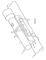
- the flashlight 16 is of a tubular construction containing either "AA" or "AAA" batteries, and having a light source at one end. The flashlight 16 is conventional and is included only to show releasable attachment to holder 10 and its operation thereof.
- holder 10 includes a base member 20, an elastic member or retaining strap 22, and bollards 24.
- the retaining strap 22 with the bollards 24 serves to releasably attach the base member 20 to the object 14.
- the retaining strap 22 wraps around a portion of the object 14 and is retained releasably in place by the bollards 24 under elastic tension.
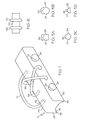
- the bollards 24 are circular and in other embodiments, the bollards may be any other shape which can releasably retains the elastic retaining strap 22.
- such shapes of the bollards 24 may include, and not to be limited to, rectangle 28, oval 30, triangle 32, and freeform 34.
- each of the bollards 24 has a shaped surface 26.
- the shaped surface 26 is a curved surface, such as concave, and in other embodiments may by an indentation 36, a partially curved surface 38, or flat surface 40.
- the shaped surface 26 goes around the entire side(s) of bollard, and in other embodiments, the shaped surface 26 may only be provided around a portion thereof.
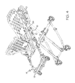
- the base member 20 serves to removably mount the holder 10 on some convenient object 14 to support both the holder 10 and the flashlight 16, as shown in FIG. 3 .
- the retaining strap 22 is situated around the object 14 and the bollards 24 as depicted by FIG. 2 , because the retaining strap 22 is maintained under elastic tension, a frictional engagement/interface will be maintained between the object 14 and the base member 20, and between the object 14 and the contacting portion of the retaining strap 22.
- This frictional interface is such that the relative rotational position of the base member 20 to the object 14 will be maintained; yet, the frictional interface can be manually overridden to manually vary the relative rotational position of the base member 20 to the object 14 without releasing the retaining strap 22 from the bollards 24.
- the base member 20 is formed from an elongate piece of material and provides a curved surface 42 on a first side and on an opposed side, a relatively flat surface 44 as best shown by FIG. 1 .
- the bollards 24 are provided and on the side 52 opposite the bollards, the elastic retaining strap 22 is attached to the base member 20.
- the curved surface 42 will mate closely with an opposing curved surface of the object 14, and edges thereof will act as legs 46 and 48 to support the holder 10 to a flat surface of the object 14.
- the base member 20 in one embodiment is a molded polymer, such as for example and not to be limited to, a high impact resistant plastic material.
- the base member 20 provides the curved surface 42 having a radius of curvature which is consistent with the shape of a tubular side frame member 54 of the cot 18.
- the base member may be formed by working such as for example, cutting, shaping, and drilling any suitable material, such as for example, and not to be limited to, wood, metals, alloys, fibrous materials, composites, into the desired shape.
- the holder 10 is provided with a pair of elastic members or retainers 56 and 58. As shown by FIG. 1 , first ends of the retainers 56 and 58 are attached to the same side as the bollards 24, and second ends thereof are attached to same side at the retaining strap 22. Accordingly, the retainers 56 and 58 span over the flat surface 44.
- the pair of elastic retainers 56 and 58 are provide in a crisscross pattern, and in other embodiments may be provided in a parallel pattern as shown by FIG. 6 .
- the pair of elastic retainers 56 and 58 is sized such that a tool 12, such as a flashlight 16, may be slipped under the retainers 56 and 58, and stretching them there around.
- a frictional engagement/interface will be maintained between the tool 12 and the base member 20, and between the tool 12 and the contacting portions of the elastic retainers 56 and 58.
- This frictional interface is such that the relative orientation/rotational position of the tool 12 to the base member 20 will be maintained; yet, the frictional interface can be manually overridden to manually vary the relative orientation/rotational position of the tool 12 to the base member 20.
- the characteristics of the both the elastic retaining strap 22, and elastic retainers 56 and 58 have an effect on the operation of the holder 10 since it is the bias force of these elastic members 22, 56, and 58 on the base member 20 which controls the frictional interfaces between the holder 10 and the object 14 and tool 12, respectively.
- the frictional interface between the holder 10 and tool 12 should be great enough that the weight of the tool 12, such as flashlight 16, is not sufficient to rotate the tool 12; however, it is not so great as to prevent the user from manually overcoming the effect of the frictional interface so that the user can manually adjust the orientation of the tool.
- the frictional interface between the holder 10 and the object 14 should be great enough that the weight of the tool 12, such as flashlight 16, is not sufficient to rotate base member 20 about the object 14; however, it is not so great as to prevent the user from manually overcoming the effect of the frictional interface so that the user can manually adjust relative rotational position of the base member 20 without having to release the retaining strap 22 from the bollards 24.
- elastic members for elastic retaining strap 22 and elastic retainers 56 and 58 may be used, in one embodiment a shock cord having a diameter ranging from 1/8 th of an inch to 1/4 th of an inch has been found satisfactory.
- the elastic members 22, 56 and 58 may be rubber tubing, rubber bands, springs, and combinations thereof
- the holder 10 provides a first quick-release mechanism, in the form of the elastic retaining strap 22 and bollards 24, to facilitate quick-release of the holder 10 from the object 14.
- holder 10 comprising a second quick-release mechanism in the form of the retainers 56 and 58, to facilitate quick-release of the tool 12 from the holder 10 independent from the first quick-release mechanism.
- the second quick-release mechanism also facilities in the embodiment when the tool 12 is a flashlight, both hands-free flashlight operation and quick-release use of the flashlight.
Landscapes
- Engineering & Computer Science (AREA)
- General Engineering & Computer Science (AREA)
- Purses, Travelling Bags, Baskets, Or Suitcases (AREA)
- Clamps And Clips (AREA)
- Workshop Equipment, Work Benches, Supports, Or Storage Means (AREA)
- Die Bonding (AREA)
- Electric Connection Of Electric Components To Printed Circuits (AREA)
- Mutual Connection Of Rods And Tubes (AREA)
- Adornments (AREA)
Claims (17)
- Halter (20) zum lösbaren Befestigen eines Werkzeugs (12) an einem Objekt (14), wobei der Halter (10) Folgendes umfasst:ein Basisglied (20);einen ersten Schnelllösemechanismus zum Erleichtern der Schnelllösung des Halters (10) von dem Objekt (14), wobei der erste Schnelllösemechanismus ein elastisches Glied (22) umfasst, das fest an dem Basisglied (20) befestigt ist, und mindestens einen Poller (24), der fest an dem Basisglied (20) befestigt ist, wobei der erste Schnelllösemechanismus eine erste Reibgrenzfläche zwischen dem Basisglied (20) und dem Objekt (14) liefert, wobei die erste Reibgrenzfläche manuell überwunden werden kann, so dass eine relative Rotationsposition des Basisglieds (20) zu dem Objekt (14) manuell justiert werden kann, ohne eine Ineingriffnahme zwischen dem elastischen Glied (22) mit dem mindestens einen Poller (24) aufzuheben;dadurch gekennzeichnet, dass das elastische Glied fest an dem Basisglied (20) befestigt ist; und der Halter weiterhin Folgendes umfasst:einen zweiten Schnelllösemechanismus zum Erleichtern der Schnelllösung des Werkzeugs (12) von dem Halter (10) unabhängig von dem ersten Schnelllösemechanismus, wobei der zweite Schnelllösemechanismus mindestens eine elastische Halterung (56) umfasst, die fest an dem Basisglied (20) befestigt ist, wobei der zweite Schnelllösemechanismus eine zweite Reibgrenzfläche zwischen dem Basisglied (20) und dem Werkzeug (12) liefert, wobei die zweite Reibgrenzfläche manuell überwunden werden kann, so dass eine Orientierung des Werkzeugs (12) relativ zu dem Basisglied (20) manuell justiert werden kann.
- Halter (10) nach Anspruch 1, wobei das Werkzeug (12) eine Taschenlampe ist.
- Halter (10) nach Anspruch 1, wobei das Objekt (14) ein Notbett ist.
- Halter (10) nach Anspruch 1, wobei der erste Schnelllösemechanismus ein Paar Poller (24) mit einer kreisförmigen Oberfläche (26) umfasst.
- Halter (10) nach Anspruch 1, wobei der erste Schnelllösemechanismus ein Paar Poller (24) umfasst, wobei die Poller (24) eine Gestalt aufweisen ausgewählt unter Rechteck, oval, kreisförmig und Dreieck.
- Halter (10) nach Anspruch 1, wobei der erste Schnelllösemechanismus ein Paar Poller (24) umfasst, wobei jeder der Poller (24) eine gestaltete Oberfläche (26) aufweist ausgewählt unter einer gekrümmten Oberfläche, einer Einprägung, einer teilweise gekrümmten Oberfläche und einer flachen Oberfläche.
- Halter (10) nach Anspruch 1, wobei das Basisglied (20) ein längliches Materialstück umfasst und eine gekrümmte Oberfläche (42) auf einer ersten Seite und eine relativ flache Oberfläche (44) auf einer der ersten Seite gegenüberliegenden Oberfläche liefert.
- Halter (10) nach Anspruch 1, wobei der erste Schnelllösemechanismus ein Paar Poller (24) umfasst und wobei das Basisglied (20) eine gekrümmte Oberfläche (42) auf einer ersten Seite liefert, wobei die Poller (24) auf einer zweiten Seite bei der ersten Seite vorgesehen sind und das elastische Glied (22) auf einer dritten Seite bei der ersten Seite vorgesehen ist.
- Halter (10) nach Anspruch 1, wobei das Basisglied (20) ein geformtes Material ist und eine gekrümmte Oberfläche (42) mit einem Krümmungsradius liefert, der mit einem Krümmungsradius des Objekts (14) übereinstimmt.
- Halter (10) nach Anspruch 1, wobei das Basisglied (20) ein Material ist ausgewählt aus Polymeren, Holz, Metallen, Legierungen, faserförmigen Materialien und Composites.
- Halter (10) nach Anspruch 1, wobei der zweite Schnelllösemechanismus ein Paar elastische Halterungen (56, 58) umfasst.
- Halter (10) nach Anspruch 1, wobei der zweite Schnelllösemechanismus ein Paar elastische Halterungen (56, 58) umfasst, die in einem kreuzweisen Muster vorgesehen sind.
- Halter (10) nach Anspruch 1, wobei der zweite Schnelllösemechanismus ein Paar elastische Halterungen (56, 58) umfasst, die in einem parallelen Muster vorgesehen sind.
- Halter (10) nach Anspruch 1, wobei der zweite Schnelllösemechanismus ein Paar elastische Halterungen (56, 58) umfasst, die jeweils einen Durchmesser im Bereich von 1/8 eines Inch bis 1/4 eines Inch aufweisen.
- Halter (10) nach Anspruch 1, wobei der erste und zweite Schnelllösemechanismus ein Material sind ausgewählt unter Spannleine, Gummischlauch, Gummibändern, Federn und Kombinationen davon.
- Halter (10) nach Anspruch 1, wobei der erste Schnelllösemechanismus ein Paar Poller (24) umfasst und wobei das Basisglied (20) eine gekrümmte Oberfläche (42) auf einer ersten Seite bereitstellt, wobei die Poller (24) des ersten Schnelllösemechanismus auf einer zweiten Seite bei der ersten Seite vorgesehen sind, das elastische Glied (22) des ersten Schnelllösemechanismus auf einer dritten Seite bei der ersten Seite vorgesehen ist und der zweite Schnelllösemechanismus ein Paar elastische Halterungen (56, 58) ist mit an der zweiten Seite befestigten ersten Enden und an der dritten Seite befestigten zweiten Enden.
- Verfahren zum Sichern eines Werkzeugs (12) an einem Objekt (14), dadurch gekennzeichnet, dass es Folgendes umfasst:Bereitstellen eines Halters (10) umfassend ein Basisglied (20); einen elastischen Halteriemen (22), Poller (24) und elastische Halterungen (56, 58), die fest an dem Basisglied (20) befestigt sind;lösbares Befestigen des Basisglieds (20) an dem Objekt (14) durch Wickeln des elastischen Halteriemens (22) um einen Abschnitt des Objekts (14) und lösbares Befestigen des elastischen Halteriemens (22) an den Pollern (24), wobei der elastische Halteriemen (22) bei Befestigung daran die Poller (24) unter elastische Zugspannung versetzt und eine erste Reibgrenzfläche zwischen dem Objekt (14) und dem Basisglied (20) liefert, wobei die erste Reibgrenzfläche manuell überwunden werden kann, so dass eine relative Rotationsposition des Basisglieds (20) zu dem Objekt (14) manuell justiert werden kann, ohne die elastische Zugspannung von den Pollern (24) aufzuheben; undlösbares Halten des Werkzeugs (12) mit den elastischen Halterungen (56, 58), wobei die elastischen Halterungen (56, 58) eine zweite Reibgrenzfläche zwischen dem Basisglied (20) und dem Werkzeug (12) befestigt, wobei die zweite Reibgrenzfläche manuell überwunden werden kann, so dass eine Orientierung des Werkzeugs (12) relativ zu dem Basisglied (20) manuell justiert werden kann.
Applications Claiming Priority (2)
| Application Number | Priority Date | Filing Date | Title |
|---|---|---|---|
| US83702606P | 2006-08-11 | 2006-08-11 | |
| PCT/US2007/074686 WO2008019239A1 (en) | 2006-08-11 | 2007-07-30 | Holder for removably attaching a tool to an object and method thereof |
Publications (2)
| Publication Number | Publication Date |
|---|---|
| EP2052182A1 EP2052182A1 (de) | 2009-04-29 |
| EP2052182B1 true EP2052182B1 (de) | 2010-05-05 |
Family
ID=38610730
Family Applications (1)
| Application Number | Title | Priority Date | Filing Date |
|---|---|---|---|
| EP07813518A Not-in-force EP2052182B1 (de) | 2006-08-11 | 2007-07-30 | Halter für lösbare befestigung eines werkzeuges an einem objekt und verfahren dafür |
Country Status (9)
| Country | Link |
|---|---|
| US (1) | US20100188863A1 (de) |
| EP (1) | EP2052182B1 (de) |
| JP (1) | JP2010500516A (de) |
| CN (1) | CN101523112A (de) |
| AT (1) | ATE467085T1 (de) |
| AU (1) | AU2007281821A1 (de) |
| CA (1) | CA2660328A1 (de) |
| DE (1) | DE602007006318D1 (de) |
| WO (1) | WO2008019239A1 (de) |
Families Citing this family (16)
| Publication number | Priority date | Publication date | Assignee | Title |
|---|---|---|---|---|
| EP2341798B1 (de) | 2008-09-03 | 2016-08-10 | Thorley Industries LLC | Säuglingspflegevorrichtung |
| US9174781B2 (en) | 2008-10-08 | 2015-11-03 | Nite Ize, Inc. | Tie wrap for bundling objects |
| USD863945S1 (en) | 2008-10-08 | 2019-10-22 | Nite Ize, Inc. | Tie |
| USD863946S1 (en) | 2008-10-08 | 2019-10-22 | Nite Ize, Inc. | Tie |
| US20110049206A1 (en) * | 2009-09-02 | 2011-03-03 | Su-Chang Liao | Tie-able securing device for bicycle |
| US8167450B2 (en) * | 2010-04-01 | 2012-05-01 | Open Water Products, Llc | Portable lighting device |
| WO2014022232A1 (en) * | 2012-07-31 | 2014-02-06 | Nite Ize, Inc. | Tie wrap for bundling objects |
| JP6341403B2 (ja) * | 2013-02-14 | 2018-06-13 | 株式会社ユピテル | システム |
| JP6193002B2 (ja) * | 2013-06-13 | 2017-09-06 | テイ・エス テック株式会社 | 照明装置の取付構造 |
| CN110239429B (zh) | 2013-06-13 | 2022-07-29 | 提爱思科技股份有限公司 | 照明装置的附接结构 |
| US20150013174A1 (en) * | 2013-07-12 | 2015-01-15 | Lynn Hanamura | Chic Stick |
| US20150257367A1 (en) * | 2014-03-11 | 2015-09-17 | Doskocil Manufacturing Company, Inc. | Illuminated Animal Exercise Device and Animal Exercise Apparatus |
| CN107642763B (zh) * | 2016-07-20 | 2020-03-27 | 海洋王(东莞)照明科技有限公司 | 固定装置以及具有该固定装置的移动灯具 |
| JP6627922B2 (ja) * | 2018-06-28 | 2020-01-08 | テイ・エス テック株式会社 | 照明装置の取付構造及び車両用ドア |
| JP7004922B2 (ja) * | 2019-12-04 | 2022-02-07 | テイ・エス テック株式会社 | 照明装置の取付構造及び車両用ドア |
| US11953192B1 (en) * | 2023-05-17 | 2024-04-09 | Brian Flannery | Fogging machine visual aid and tuning device |
Family Cites Families (23)
| Publication number | Priority date | Publication date | Assignee | Title |
|---|---|---|---|---|
| US1321842A (en) * | 1919-11-18 | Support for fishing rods | ||
| US1318850A (en) * | 1919-10-14 | Job de tostg | ||
| US1320934A (en) * | 1919-11-04 | Flash-light attachment | ||
| US1222458A (en) * | 1916-03-07 | 1917-04-10 | John A Peterson | Holder for lamps or headlights. |
| US1200403A (en) * | 1916-03-28 | 1916-10-03 | Nick Weyer | Holder for electric flash-lights. |
| US1735212A (en) * | 1928-12-15 | 1929-11-12 | Wald Mfg Company | Flash-light support |
| US1923962A (en) * | 1932-01-18 | 1933-08-22 | Ernest W Worley | Flash light |
| US3273766A (en) * | 1964-11-02 | 1966-09-20 | Frank P Cosentino | Wrist article retaining device |
| US3550824A (en) * | 1968-11-18 | 1970-12-29 | Madeline M Bohanski | Adjustable support for wrist |
| US4214688A (en) * | 1978-10-19 | 1980-07-29 | Griffin Groves L Jr | Tool mounting assembly |
| US4541555A (en) * | 1983-12-07 | 1985-09-17 | Miree Mallory F | Method and apparatus for mounting flashlights to bicycles |
| US5154506A (en) * | 1991-06-17 | 1992-10-13 | Leard Ronald R | Flashlight armband |
| US5181774A (en) * | 1992-01-08 | 1993-01-26 | Lee Lane | Lamp bracket |
| US5144546A (en) * | 1992-02-03 | 1992-09-01 | Lumitech, Inc. | Flashlight holder |
| US5335149A (en) * | 1992-05-13 | 1994-08-02 | Sierra Sun Holdings Ltd. | Method and apparatus for holding a light on a boat |
| US5407164A (en) * | 1993-12-15 | 1995-04-18 | Quinn; Joseph F. | Holder for a window sill |
| DE29500193U1 (de) | 1995-01-10 | 1995-02-23 | Fa. Lupine Bikes & Equipement, 92348 Berg | Fahrradlampe |
| US5601356A (en) * | 1995-06-16 | 1997-02-11 | Mcwilliams; Dean K. | Flashlight stand and wrist mount system |
| US5893496A (en) * | 1995-08-01 | 1999-04-13 | Katz; Rodney | Utility headband and holster system |
| US6062447A (en) * | 1997-07-10 | 2000-05-16 | Longley; Halliwell M. | Molded quick-release buckle and forearm support strap |
| US6536911B1 (en) | 2000-11-21 | 2003-03-25 | Diangelo Pasquale F. | Flashlight holder |
| US7000809B1 (en) * | 2003-05-20 | 2006-02-21 | John Timothy Stroud | Mini-flashlight sling |
| US6908216B2 (en) * | 2003-07-17 | 2005-06-21 | Jack G. Love | Flashlight holder for fishing net |
-
2007
- 2007-07-30 JP JP2009523897A patent/JP2010500516A/ja not_active Abandoned
- 2007-07-30 EP EP07813518A patent/EP2052182B1/de not_active Not-in-force
- 2007-07-30 CN CN200780036640.6A patent/CN101523112A/zh active Pending
- 2007-07-30 WO PCT/US2007/074686 patent/WO2008019239A1/en not_active Ceased
- 2007-07-30 CA CA002660328A patent/CA2660328A1/en not_active Abandoned
- 2007-07-30 AT AT07813518T patent/ATE467085T1/de not_active IP Right Cessation
- 2007-07-30 US US12/377,194 patent/US20100188863A1/en not_active Abandoned
- 2007-07-30 DE DE602007006318T patent/DE602007006318D1/de not_active Expired - Fee Related
- 2007-07-30 AU AU2007281821A patent/AU2007281821A1/en not_active Abandoned
Also Published As
| Publication number | Publication date |
|---|---|
| AU2007281821A1 (en) | 2008-02-14 |
| JP2010500516A (ja) | 2010-01-07 |
| CN101523112A (zh) | 2009-09-02 |
| EP2052182A1 (de) | 2009-04-29 |
| ATE467085T1 (de) | 2010-05-15 |
| US20100188863A1 (en) | 2010-07-29 |
| CA2660328A1 (en) | 2008-02-14 |
| WO2008019239A1 (en) | 2008-02-14 |
| DE602007006318D1 (de) | 2010-06-17 |
Similar Documents
| Publication | Publication Date | Title |
|---|---|---|
| EP2052182B1 (de) | Halter für lösbare befestigung eines werkzeuges an einem objekt und verfahren dafür | |
| US6749166B2 (en) | Flashlight holder | |
| US5601356A (en) | Flashlight stand and wrist mount system | |
| US8545041B2 (en) | Mounting clip | |
| US4974764A (en) | Belt clip | |
| US4214688A (en) | Tool mounting assembly | |
| US8387939B2 (en) | Mounting support with light | |
| US5056700A (en) | Automobile mountable bicycle carrier | |
| US20110222274A1 (en) | Hands-Free Multi-Positional Task Light and Method of Use Thereof | |
| US20070195983A1 (en) | Combination wind screen and microphone shock mount | |
| JP2019511380A5 (de) | ||
| US5901930A (en) | Cord strain relief device for reducing cumulative trauma disorders | |
| US20070138227A1 (en) | Tool Holder | |
| WO2008055075A2 (en) | Cigar holder | |
| US20010008246A1 (en) | Locking tool holder | |
| US7051406B1 (en) | Apparatus holder for hats | |
| EP2817553A1 (de) | Verbindungsvorrichtung | |
| AU2014201078A1 (en) | Self-positioning light filtering device and replaceable filter | |
| GB2512279A (en) | A mount device | |
| CA2333823C (en) | Third hand for a flashlight having pivotal arm and mounting mechanism | |
| KR200489527Y1 (ko) | 목걸이형 휴대용 선풍기 거치대 | |
| US20030161139A1 (en) | Shoulder mount for flashlight | |
| US20050183760A1 (en) | Portable vehicle canopy | |
| US9500316B2 (en) | System and apparatus for the support of optics | |
| US7703938B1 (en) | Flashlight mounting clip |
Legal Events
| Date | Code | Title | Description |
|---|---|---|---|
| PUAI | Public reference made under article 153(3) epc to a published international application that has entered the european phase |
Free format text: ORIGINAL CODE: 0009012 |
|
| 17P | Request for examination filed |
Effective date: 20090306 |
|
| AK | Designated contracting states |
Kind code of ref document: A1 Designated state(s): AT BE BG CH CY CZ DE DK EE ES FI FR GB GR HU IE IS IT LI LT LU LV MC MT NL PL PT RO SE SI SK TR |
|
| AX | Request for extension of the european patent |
Extension state: AL BA HR MK RS |
|
| RIN1 | Information on inventor provided before grant (corrected) |
Inventor name: WEST, SCOTT |
|
| 17Q | First examination report despatched |
Effective date: 20090625 |
|
| GRAP | Despatch of communication of intention to grant a patent |
Free format text: ORIGINAL CODE: EPIDOSNIGR1 |
|
| DAX | Request for extension of the european patent (deleted) | ||
| RIN1 | Information on inventor provided before grant (corrected) |
Inventor name: WEST, SCOTT |
|
| GRAS | Grant fee paid |
Free format text: ORIGINAL CODE: EPIDOSNIGR3 |
|
| GRAA | (expected) grant |
Free format text: ORIGINAL CODE: 0009210 |
|
| AK | Designated contracting states |
Kind code of ref document: B1 Designated state(s): AT BE BG CH CY CZ DE DK EE ES FI FR GB GR HU IE IS IT LI LT LU LV MC MT NL PL PT RO SE SI SK TR |
|
| REG | Reference to a national code |
Ref country code: GB Ref legal event code: FG4D |
|
| REG | Reference to a national code |
Ref country code: CH Ref legal event code: EP |
|
| REG | Reference to a national code |
Ref country code: IE Ref legal event code: FG4D |
|
| REF | Corresponds to: |
Ref document number: 602007006318 Country of ref document: DE Date of ref document: 20100617 Kind code of ref document: P |
|
| REG | Reference to a national code |
Ref country code: NL Ref legal event code: VDEP Effective date: 20100505 |
|
| LTIE | Lt: invalidation of european patent or patent extension |
Effective date: 20100505 |
|
| PG25 | Lapsed in a contracting state [announced via postgrant information from national office to epo] |
Ref country code: ES Free format text: LAPSE BECAUSE OF FAILURE TO SUBMIT A TRANSLATION OF THE DESCRIPTION OR TO PAY THE FEE WITHIN THE PRESCRIBED TIME-LIMIT Effective date: 20100816 Ref country code: LT Free format text: LAPSE BECAUSE OF FAILURE TO SUBMIT A TRANSLATION OF THE DESCRIPTION OR TO PAY THE FEE WITHIN THE PRESCRIBED TIME-LIMIT Effective date: 20100505 Ref country code: NL Free format text: LAPSE BECAUSE OF FAILURE TO SUBMIT A TRANSLATION OF THE DESCRIPTION OR TO PAY THE FEE WITHIN THE PRESCRIBED TIME-LIMIT Effective date: 20100505 Ref country code: SE Free format text: LAPSE BECAUSE OF FAILURE TO SUBMIT A TRANSLATION OF THE DESCRIPTION OR TO PAY THE FEE WITHIN THE PRESCRIBED TIME-LIMIT Effective date: 20100505 |
|
| PG25 | Lapsed in a contracting state [announced via postgrant information from national office to epo] |
Ref country code: AT Free format text: LAPSE BECAUSE OF FAILURE TO SUBMIT A TRANSLATION OF THE DESCRIPTION OR TO PAY THE FEE WITHIN THE PRESCRIBED TIME-LIMIT Effective date: 20100505 Ref country code: FI Free format text: LAPSE BECAUSE OF FAILURE TO SUBMIT A TRANSLATION OF THE DESCRIPTION OR TO PAY THE FEE WITHIN THE PRESCRIBED TIME-LIMIT Effective date: 20100505 Ref country code: IS Free format text: LAPSE BECAUSE OF FAILURE TO SUBMIT A TRANSLATION OF THE DESCRIPTION OR TO PAY THE FEE WITHIN THE PRESCRIBED TIME-LIMIT Effective date: 20100905 Ref country code: LV Free format text: LAPSE BECAUSE OF FAILURE TO SUBMIT A TRANSLATION OF THE DESCRIPTION OR TO PAY THE FEE WITHIN THE PRESCRIBED TIME-LIMIT Effective date: 20100505 Ref country code: SI Free format text: LAPSE BECAUSE OF FAILURE TO SUBMIT A TRANSLATION OF THE DESCRIPTION OR TO PAY THE FEE WITHIN THE PRESCRIBED TIME-LIMIT Effective date: 20100505 |
|
| PG25 | Lapsed in a contracting state [announced via postgrant information from national office to epo] |
Ref country code: CY Free format text: LAPSE BECAUSE OF FAILURE TO SUBMIT A TRANSLATION OF THE DESCRIPTION OR TO PAY THE FEE WITHIN THE PRESCRIBED TIME-LIMIT Effective date: 20100609 Ref country code: PL Free format text: LAPSE BECAUSE OF FAILURE TO SUBMIT A TRANSLATION OF THE DESCRIPTION OR TO PAY THE FEE WITHIN THE PRESCRIBED TIME-LIMIT Effective date: 20100505 |
|
| PG25 | Lapsed in a contracting state [announced via postgrant information from national office to epo] |
Ref country code: DK Free format text: LAPSE BECAUSE OF FAILURE TO SUBMIT A TRANSLATION OF THE DESCRIPTION OR TO PAY THE FEE WITHIN THE PRESCRIBED TIME-LIMIT Effective date: 20100505 Ref country code: EE Free format text: LAPSE BECAUSE OF FAILURE TO SUBMIT A TRANSLATION OF THE DESCRIPTION OR TO PAY THE FEE WITHIN THE PRESCRIBED TIME-LIMIT Effective date: 20100505 Ref country code: PT Free format text: LAPSE BECAUSE OF FAILURE TO SUBMIT A TRANSLATION OF THE DESCRIPTION OR TO PAY THE FEE WITHIN THE PRESCRIBED TIME-LIMIT Effective date: 20100906 |
|
| PG25 | Lapsed in a contracting state [announced via postgrant information from national office to epo] |
Ref country code: BE Free format text: LAPSE BECAUSE OF FAILURE TO SUBMIT A TRANSLATION OF THE DESCRIPTION OR TO PAY THE FEE WITHIN THE PRESCRIBED TIME-LIMIT Effective date: 20100505 Ref country code: MC Free format text: LAPSE BECAUSE OF NON-PAYMENT OF DUE FEES Effective date: 20100731 Ref country code: RO Free format text: LAPSE BECAUSE OF FAILURE TO SUBMIT A TRANSLATION OF THE DESCRIPTION OR TO PAY THE FEE WITHIN THE PRESCRIBED TIME-LIMIT Effective date: 20100505 Ref country code: SK Free format text: LAPSE BECAUSE OF FAILURE TO SUBMIT A TRANSLATION OF THE DESCRIPTION OR TO PAY THE FEE WITHIN THE PRESCRIBED TIME-LIMIT Effective date: 20100505 Ref country code: CZ Free format text: LAPSE BECAUSE OF FAILURE TO SUBMIT A TRANSLATION OF THE DESCRIPTION OR TO PAY THE FEE WITHIN THE PRESCRIBED TIME-LIMIT Effective date: 20100505 |
|
| PLBE | No opposition filed within time limit |
Free format text: ORIGINAL CODE: 0009261 |
|
| STAA | Information on the status of an ep patent application or granted ep patent |
Free format text: STATUS: NO OPPOSITION FILED WITHIN TIME LIMIT |
|
| PG25 | Lapsed in a contracting state [announced via postgrant information from national office to epo] |
Ref country code: IT Free format text: LAPSE BECAUSE OF FAILURE TO SUBMIT A TRANSLATION OF THE DESCRIPTION OR TO PAY THE FEE WITHIN THE PRESCRIBED TIME-LIMIT Effective date: 20100505 |
|
| 26N | No opposition filed |
Effective date: 20110208 |
|
| REG | Reference to a national code |
Ref country code: FR Ref legal event code: ST Effective date: 20110331 |
|
| PG25 | Lapsed in a contracting state [announced via postgrant information from national office to epo] |
Ref country code: DE Free format text: LAPSE BECAUSE OF NON-PAYMENT OF DUE FEES Effective date: 20110201 |
|
| REG | Reference to a national code |
Ref country code: DE Ref legal event code: R119 Ref document number: 602007006318 Country of ref document: DE Effective date: 20110201 |
|
| PG25 | Lapsed in a contracting state [announced via postgrant information from national office to epo] |
Ref country code: GR Free format text: LAPSE BECAUSE OF FAILURE TO SUBMIT A TRANSLATION OF THE DESCRIPTION OR TO PAY THE FEE WITHIN THE PRESCRIBED TIME-LIMIT Effective date: 20100806 Ref country code: FR Free format text: LAPSE BECAUSE OF NON-PAYMENT OF DUE FEES Effective date: 20100802 |
|
| REG | Reference to a national code |
Ref country code: DE Ref legal event code: R097 Ref document number: 602007006318 Country of ref document: DE Effective date: 20110208 |
|
| PG25 | Lapsed in a contracting state [announced via postgrant information from national office to epo] |
Ref country code: IE Free format text: LAPSE BECAUSE OF NON-PAYMENT OF DUE FEES Effective date: 20100730 |
|
| PG25 | Lapsed in a contracting state [announced via postgrant information from national office to epo] |
Ref country code: MT Free format text: LAPSE BECAUSE OF FAILURE TO SUBMIT A TRANSLATION OF THE DESCRIPTION OR TO PAY THE FEE WITHIN THE PRESCRIBED TIME-LIMIT Effective date: 20100505 |
|
| REG | Reference to a national code |
Ref country code: CH Ref legal event code: PL |
|
| GBPC | Gb: european patent ceased through non-payment of renewal fee |
Effective date: 20110730 |
|
| PG25 | Lapsed in a contracting state [announced via postgrant information from national office to epo] |
Ref country code: LI Free format text: LAPSE BECAUSE OF NON-PAYMENT OF DUE FEES Effective date: 20110731 Ref country code: CH Free format text: LAPSE BECAUSE OF NON-PAYMENT OF DUE FEES Effective date: 20110731 |
|
| PG25 | Lapsed in a contracting state [announced via postgrant information from national office to epo] |
Ref country code: GB Free format text: LAPSE BECAUSE OF NON-PAYMENT OF DUE FEES Effective date: 20110730 |
|
| PG25 | Lapsed in a contracting state [announced via postgrant information from national office to epo] |
Ref country code: HU Free format text: LAPSE BECAUSE OF FAILURE TO SUBMIT A TRANSLATION OF THE DESCRIPTION OR TO PAY THE FEE WITHIN THE PRESCRIBED TIME-LIMIT Effective date: 20101106 Ref country code: BG Free format text: LAPSE BECAUSE OF FAILURE TO SUBMIT A TRANSLATION OF THE DESCRIPTION OR TO PAY THE FEE WITHIN THE PRESCRIBED TIME-LIMIT Effective date: 20100505 Ref country code: LU Free format text: LAPSE BECAUSE OF NON-PAYMENT OF DUE FEES Effective date: 20100730 |
|
| PG25 | Lapsed in a contracting state [announced via postgrant information from national office to epo] |
Ref country code: TR Free format text: LAPSE BECAUSE OF FAILURE TO SUBMIT A TRANSLATION OF THE DESCRIPTION OR TO PAY THE FEE WITHIN THE PRESCRIBED TIME-LIMIT Effective date: 20100505 |
|
| PG25 | Lapsed in a contracting state [announced via postgrant information from national office to epo] |
Ref country code: BG Free format text: LAPSE BECAUSE OF FAILURE TO SUBMIT A TRANSLATION OF THE DESCRIPTION OR TO PAY THE FEE WITHIN THE PRESCRIBED TIME-LIMIT Effective date: 20100805 |