EP2051745B1 - Device for verifying the cleaning and disinfection result of diagnostic and surgical instruments which are especially cleaned in automatic washers - Google Patents
Device for verifying the cleaning and disinfection result of diagnostic and surgical instruments which are especially cleaned in automatic washers Download PDFInfo
- Publication number
- EP2051745B1 EP2051745B1 EP07724798A EP07724798A EP2051745B1 EP 2051745 B1 EP2051745 B1 EP 2051745B1 EP 07724798 A EP07724798 A EP 07724798A EP 07724798 A EP07724798 A EP 07724798A EP 2051745 B1 EP2051745 B1 EP 2051745B1
- Authority
- EP
- European Patent Office
- Prior art keywords
- test
- accordance
- chamber
- shaped
- cleaning
- Prior art date
- Legal status (The legal status is an assumption and is not a legal conclusion. Google has not performed a legal analysis and makes no representation as to the accuracy of the status listed.)
- Active
Links
Images


Classifications
-
- A—HUMAN NECESSITIES
- A61—MEDICAL OR VETERINARY SCIENCE; HYGIENE
- A61B—DIAGNOSIS; SURGERY; IDENTIFICATION
- A61B1/00—Instruments for performing medical examinations of the interior of cavities or tubes of the body by visual or photographical inspection, e.g. endoscopes; Illuminating arrangements therefor
- A61B1/00002—Operational features of endoscopes
- A61B1/00057—Operational features of endoscopes provided with means for testing or calibration
-
- A—HUMAN NECESSITIES
- A61—MEDICAL OR VETERINARY SCIENCE; HYGIENE
- A61B—DIAGNOSIS; SURGERY; IDENTIFICATION
- A61B1/00—Instruments for performing medical examinations of the interior of cavities or tubes of the body by visual or photographical inspection, e.g. endoscopes; Illuminating arrangements therefor
- A61B1/12—Instruments for performing medical examinations of the interior of cavities or tubes of the body by visual or photographical inspection, e.g. endoscopes; Illuminating arrangements therefor with cooling or rinsing arrangements
- A61B1/121—Instruments for performing medical examinations of the interior of cavities or tubes of the body by visual or photographical inspection, e.g. endoscopes; Illuminating arrangements therefor with cooling or rinsing arrangements provided with means for cleaning post-use
- A61B1/125—Instruments for performing medical examinations of the interior of cavities or tubes of the body by visual or photographical inspection, e.g. endoscopes; Illuminating arrangements therefor with cooling or rinsing arrangements provided with means for cleaning post-use using fluid circuits
-
- A—HUMAN NECESSITIES
- A61—MEDICAL OR VETERINARY SCIENCE; HYGIENE
- A61B—DIAGNOSIS; SURGERY; IDENTIFICATION
- A61B90/00—Instruments, implements or accessories specially adapted for surgery or diagnosis and not covered by any of the groups A61B1/00 - A61B50/00, e.g. for luxation treatment or for protecting wound edges
- A61B90/70—Cleaning devices specially adapted for surgical instruments
-
- A—HUMAN NECESSITIES
- A61—MEDICAL OR VETERINARY SCIENCE; HYGIENE
- A61L—METHODS OR APPARATUS FOR STERILISING MATERIALS OR OBJECTS IN GENERAL; DISINFECTION, STERILISATION OR DEODORISATION OF AIR; CHEMICAL ASPECTS OF BANDAGES, DRESSINGS, ABSORBENT PADS OR SURGICAL ARTICLES; MATERIALS FOR BANDAGES, DRESSINGS, ABSORBENT PADS OR SURGICAL ARTICLES
- A61L2/00—Methods or apparatus for disinfecting or sterilising materials or objects other than foodstuffs or contact lenses; Accessories therefor
- A61L2/26—Accessories or devices or components used for biocidal treatment
- A61L2/28—Devices for testing the effectiveness or completeness of sterilisation, e.g. indicators which change colour
-
- A—HUMAN NECESSITIES
- A61—MEDICAL OR VETERINARY SCIENCE; HYGIENE
- A61B—DIAGNOSIS; SURGERY; IDENTIFICATION
- A61B17/00—Surgical instruments, devices or methods, e.g. tourniquets
- A61B2017/00681—Aspects not otherwise provided for
- A61B2017/00707—Dummies, phantoms; Devices simulating patient or parts of patient
-
- A—HUMAN NECESSITIES
- A61—MEDICAL OR VETERINARY SCIENCE; HYGIENE
- A61B—DIAGNOSIS; SURGERY; IDENTIFICATION
- A61B17/00—Surgical instruments, devices or methods, e.g. tourniquets
- A61B2017/00681—Aspects not otherwise provided for
- A61B2017/00725—Calibration or performance testing
-
- A—HUMAN NECESSITIES
- A61—MEDICAL OR VETERINARY SCIENCE; HYGIENE
- A61B—DIAGNOSIS; SURGERY; IDENTIFICATION
- A61B90/00—Instruments, implements or accessories specially adapted for surgery or diagnosis and not covered by any of the groups A61B1/00 - A61B50/00, e.g. for luxation treatment or for protecting wound edges
- A61B90/70—Cleaning devices specially adapted for surgical instruments
- A61B2090/701—Cleaning devices specially adapted for surgical instruments for flexible tubular instruments, e.g. endoscopes
-
- A—HUMAN NECESSITIES
- A61—MEDICAL OR VETERINARY SCIENCE; HYGIENE
- A61B—DIAGNOSIS; SURGERY; IDENTIFICATION
- A61B90/00—Instruments, implements or accessories specially adapted for surgery or diagnosis and not covered by any of the groups A61B1/00 - A61B50/00, e.g. for luxation treatment or for protecting wound edges
- A61B90/70—Cleaning devices specially adapted for surgical instruments
- A61B2090/702—Devices for testing the cleaning process, e.g. test soils
Definitions
- the invention relates to a device for checking the cleaning and disinfecting results in particular in washing machines cleaned diagnostic and / or surgical instruments with box-shaped and cannula-shaped components, such as endoscopes.
- Such devices should be used to verify that cleaned instruments of the aforementioned type are free from bodily fluids, such as blood, after being cleaned after use both on the outer surface and in the cavities of the instrument. Tissue fluid or secretions that may be contaminated with pathogens of any kind.
- test system which consists of a first and a second hollow body, which are connectable to each other, wherein in the connecting region of the two hollow bodies, a test body can be introduced.
- This test system can only be used to check the cleaning performance of a washing machine in connection with cannula-shaped components of a diagnostic and / or surgical instrument and, moreover, due to its design, is unable to simulate the overall situation in a diagnostic and / or surgical instrument.
- test systems are known in which the flow volume or at a constriction of the inner cavity of the cannular working part constructive dynamic pressure is measured and conclusions are drawn on the residual contamination of the cannular working part or the cleaning performance of a washing machine based on the measurement result.
- this system does not simulate the overall situation in a diagnostic and / or surgical instrument.
- the result obtained is only relative and can not say anything about the nature of the pollution.
- US 2003/0012688 A1 US 2003/0215923 A1 and EP 1 488 757 A1 describe apparatus and methods for determining or checking the cleaning and disinfecting effect of washing machines of clinical instruments, such as endoscopes. Devices and methods can be used to assess the effectiveness of the cleaning or disinfection in the working part of an endoscope.
- the WO 2005/053755 A1 describes a device for checking the cleaning result in a cleaned in washing machine endoscope, which is designed as a dummy of the endoscope. If appropriate, these are a plurality of test bodies or test tubes, such as an operating part and a working part, corresponding to the different parts of an endoscope.
- the specimens are equipped with test chambers for arranging a test element with test contamination, such as a two-part designed test chamber.
- the devices known from the prior art generally have the disadvantage that only the cleaning and disinfecting results with respect to the cannula-shaped component can be checked with them.
- the housing-shaped component can be with the known devices only check whether the outer surface has been cleaned according to the requirements. This represents, especially in the case of one-part instruments, in which the flexible cannula-shaped component is inseparably connected to the housing-shaped component, a risk not to be underestimated of residual contamination remaining, in particular, in the housing-shaped component or in the connection area between it and the cannula-shaped component.
- the invention is therefore based on the object to provide an improved device for checking the cleaning and disinfecting results in particular in washing machines cleaned and / or disinfected diagnostic and / or surgical instruments with housing-shaped and / or cannula-shaped components, with which avoided the disadvantages described above and that allows a comprehensive review of the cleaning and disinfecting results of such an instrument.
- the invention solves this problem with a device according to claim 1 advantageous embodiments are included in the Unterausp mousse.
- the device is a dummy of the diagnostic and / or surgical instrument. It is at least one receptacle for arranging a test element having a test soiling in or on a test body which corresponds to the housing-shaped component of the instrument and is provided in the course of a test tube which corresponds to the cannula-shaped component, wherein the housing-shaped test body and the test tube are detachably connectable to each other by means of a connection device.
- the basic idea of the invention therefore consists in that the device represents a dummy of the diagnostic and / or surgical instrument to be cleaned / disinfected, which consists of separate parts that can be checked and detached from each other at different points and sections, in contrast to the original instrumentation can be provided with a test soil having a test element.
- This dummy is then subjected to a cleaning and disinfection process instead of the real instrument in a washing machine. It can also be determined on the basis of the test elements whether the washing machine achieves cleaning and disinfection results in all parts of the instrument which correspond to the relevant hygiene and safety regulations.
- the housing-shaped component is an operating part and the cannula-shaped component is a working part of the endoscope. Due to this preference, the further illustration of the invention essentially deals with an endoscope dummy. Due to the detachable connection of the test tube with the test specimen, the inlet or outlet opening on the test specimen corresponding to the test tube can be more easily checked after the washing process by removing the test tube from the test specimen.
- the box-shaped test body has at its peripheral surface at least one outer receiving device for fastening at least one test element having a test soiling.
- the cleaning and disinfection result on the outer surface of the control unit of the endoscope was checked by having attached to the peripheral surface of the control panel inspection elements, for example by means of cable ties.
- the recording device according to the invention slipping or even detachment of the test elements from the operating element of the endoscope is prevented, so that now a reliable statement about the cleaning and disinfection result can be made.
- the connecting device is designed for connecting the test body to the test hose for receiving a test element having a test soiling.
- the test tube can be separated from the test specimen after the washing process and the cleaning and disinfection result can be determined on the basis of the test element located in the receiving device.
- the connecting device can serve as the first test chamber for receiving a test element.
- connection device is formed by a screw or a connector, but the fact is crucial that the cleaning and disinfection result of the transition point from the control panel to the working part can be checked with the novel device.
- the housing-shaped test specimen as a further embodiment of the invention provides a test valve head corresponding to the valve head of an endoscope for introducing, for example, cleaning fluid into the test tube and at least one further connection device for connecting the test specimen with another test tube, preferably a tubular supply part for introducing Compressed air, on, achieves an even more hands-on testing device for all types of endoscopes.
- the respective connecting parts for receiving a test element can be configured with test contaminants.
- the transport channel of the further connecting device leads into a chamber separated from the transport channel of the test body, so that the functionality of a leak-testing device can be tested with a test hose connected to the connecting device, which corresponds to the supply part of an endoscope for introducing compressed air.
- a two-part configured first test chamber for receiving a test element sealingly used.
- vertical transport channels for example, those of a Luer-Lock with the optical channel, meet one another, so that here is a review of the cleaning performance is particularly important.
- test chamber comes to rest at a distance from the transport channel of such a connection device. Since the test chamber in this case is not part of the actual test body, but is introduced into this, the test chamber is provided with holes so that a test element arranged therein can be reliably washed around by liquid.
- This first test chamber is held in a suitable manner by means of screw, snap, bayonet or the like sealing sealing in the test specimen.
- a second test chamber for receiving a test element is integrated, which is preferably formed of a cylindrical sleeve and a captive and slidably held therein punch for receiving the test element.
- the review of the cleaning performance is in terms of the tube part of endoscopes and such instruments of particular interest, since these hose parts often have very small cross-sections, respectively, diameter of sometimes only 1 to 3 mm.
- the tube diameters of the instrument dummies according to the invention are not limited and can be adapted to the particular case.
- the images for the arrangement of a test soil having a test element are standardized on standard test elements.
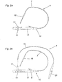
- a one-piece flexible endoscope 1 shown, in which the tubular working part 3 is permanently connected to the control unit 2.
- a supply part 5 is arranged at the free end of a valve 17 for
- the operating part 2 of an endoscope 1 has a valve head 4, via which, for example, medical instruments can be introduced into the working part 3 of the endoscope 1.
- the image optics 16 is arranged, which is connected to the probe arranged at the free end of the working part 3 via running in the working part 3 glass fiber bundles.
- test specimens designed to receive a test element having a test soiling have developed.
- test specimens which, although tubular, can not simulate the working part of an endoscope
- a more or less accurate statement can be made as to whether or not the working part 3 of an endoscope 1 is cleaned during the washing process. But whether the complete instrument 1 and in particular the control panel 2 or the transition point from the control panel 2 to the working part 3 is properly cleaned, can not be determined with such specimens alone, and the safety of the review for the working part is not completely given.
- the device 6 in addition to a test tube 7, also has a test body 8 which corresponds to the housing-shaped operating part 2 of an endoscope 1, as shown in FIG Fig. 2a is shown.
- a second test chamber 18 is arranged, which is for receiving a Test element 14 is used and will be described in more detail below.
- the test tube 7 is detachably connected to the test body 8 via a connecting device 10.
- the test specimen 8 of the exemplary embodiment shown has two further connecting devices 11 for connecting the test specimen 8 to further test tubes.
- test tube 19 is in the in Fig. 2b embodiment shown connected via the connecting device 11 with the test specimen 8.
- the test tube 19 corresponds to the in Fig. 1a shown supply part 5 of the endoscope 1, wherein on the test body 8 opposite end of the test tube 19, a test valve 20 is arranged for introducing compressed air. This measure is used to check the tightness of the device at an operating pressure specified by the washing machine manufacturer.
- the test body 8 also has a test valve head 9 and a plurality of receiving devices 13, which are formed on the circumferential surface 12 in the form of groove-shaped cutouts or pockets ( Fig. 3 ) and in which the test elements 14 are held captive.
- the test elements 14 can be fastened in the receiving areas 13 via fastening means 23.
- Testanschmutz Institute 15 are applied, which may for example be synthetically produced or formed from fresh human, bovine citrate or mutton blood ( Fig. 5a, 5b ).
- test valve head 9 different attachments 21, 22 are arranged, which serve for example the introduction of water or compressed air.
- a special feature in this context is the article 21, which is in the form of a T-piece and the simultaneous or alternative introduction of a probe and / or water and / or cleaning liquid in the test valve head 9 is used ( Fig. 4 ).
- connection part 10 and the transition 10 'to the test body are designed such that a test element 14 with test contaminants 15 can be arranged therein.
- the connection part 10 thus forms, together with the transition 10 ', a first test chamber for a critical area within an endoscope, where the biopsy channel of the operating part strikes the flexible working part of an endoscope.
- connection part 10 in cross section (a) and in side view (b) is shown.
- the interior is divided into two areas 10.1 and 10.2, which makes the connection part 10 suitable for receiving test elements of different dimensions.
- a test element of 5x56x1 (mm) would pass through both areas 10.1 and 10.2, whereas a test element of 6.5x30x0.8 (mm) would penetrate only in the area 10.2.
- the test element 14 is not completely absorbed by the connection part 10, but about halfway into the transition 10 'of the test specimen 8 (see. Fig. 6 protrudes when test specimen 8 and test tube 7 are connected to each other.
- Fig. 8 shows attachment and design of a first test chamber 24, which is sealingly insertable at the end remote from the test tube end of the test piece 8.
- Fig. 8a schematically shows a section through an entire specimen 8, in which in particular the course and the arrangement of the water, air and biopsy channels of an endoscope are modeled.
- a receptacle or opening 28 is provided through which the first test chamber 24 (FIG. Fig. 8b ) and can be tightly connected to the test specimen 8.
- the first testing chamber 24 must come to lie approximately at the level of the opening 29, which is the access to a water / air channel of an endoscope and the dummy as a detergent supply serves.
- the first test chamber 24 is designed in two parts.
- an extended punch 30, which can be tightly connected by means of screw, snap, bayonet or the like compound 31 with the test piece 8, at the end facing away from the joint 36 is hollow and provided with a screw thread 32, for example.
- This hollow region forms a first volume part 33 of the first test specimen 24.
- the second volume part 34 is formed by a sleeve 35, which can be connected to the first volume part 33.
- a test element 14 can be held captive by the sleeve inner diameter at the end of the sleeve 35 is less than at the junction to the first space part 33.
- a second test chamber 18 outlines how it is arranged according to the invention in the test tube 7.
- This test chamber 18 can be opened and closed, for example, again with a screw, snap, bayonet or the like compound, but is not separable.
- a sleeve 36 has centrally in its interior a rod 37, via which a second sleeve 38 is guided, such that in the extended state, the sleeve 38 is anchored to the rod.
- the sleeve 38 has a flattened region 39 on which the test element 14 can be mounted. Both ends 40 and 40 'are connected to the test tube 7 and the chamber is flowed through during a test cleaning passage of liquid.
- the invention provides by the possibility of arrangement of test elements 14 with one or more educable 15 in the course of educaschlauches 7, in the transition point from the test tube 7 to the test specimen 8, in the region of the water / air channel and on the peripheral surface 12 of the test specimen 8 a with respect to the state
- the technique greatly improved and reliable Verification possibility of the cleaning and disinfection of cleaned in washing machines instruments, especially endoscopes.
- the other test tubes 19, which simulate a supply tube 5, may be equipped with these features.
Abstract
Description
Die Erfindung betrifft eine Vorrichtung zur Überprüfung des Reinigungs- und Desinfektionsergebnisses bei insbesondere in Waschautomaten gereinigten diagnostischen und/oder chirurgischen Instrumenten mit gehäuseförmigen und kanülenförmigen Bauteilen, wie Endoskopen.The invention relates to a device for checking the cleaning and disinfecting results in particular in washing machines cleaned diagnostic and / or surgical instruments with box-shaped and cannula-shaped components, such as endoscopes.
Mit solchen Vorrichtungen soll überprüft werden, ob gereinigte Instrumente der vorgenannten Art nach einem nach der Anwendung vorzunehmenden Reinigungsvorgang sowohl an der Außenfläche als auch in Hohlräumen des Instrumentes frei von Körperfluiden sind, mit welchen diese bei der Anwendung in Kontakt gebracht wurden, wie beispielsweise Blut, Gewebsflüssigkeit oder Sekrete, die mit Erregern jeglicher Art kontaminiert sein können.Such devices should be used to verify that cleaned instruments of the aforementioned type are free from bodily fluids, such as blood, after being cleaned after use both on the outer surface and in the cavities of the instrument. Tissue fluid or secretions that may be contaminated with pathogens of any kind.
Zu diesem Zweck ist aus der
Weiters sind Prüfsysteme bekannt, bei denen das Durchflussvolumen bzw. der sich bei einer Verengung des innenliegenden Hohlraums des kanülenförmigen Arbeitsteiles aufbauende Staudruck gemessen wird und anhand des Messergebnisses Rückschlüsse auf die Restverschmutzung des kanülenförmigen Arbeitsteils bzw. die Reinigungsleistung eines Waschautomaten gezogen werden. Wieder lässt sich mit diesem System nicht die Gesamtsituation in einem diagnostischen und/oder chirurgischen Instrument simulieren. Darüber hinaus ist das erhaltene Ergebnis lediglich relativ und kann nichts über die Art der Verschmutzung aussagen.Furthermore, test systems are known in which the flow volume or at a constriction of the inner cavity of the cannular working part constructive dynamic pressure is measured and conclusions are drawn on the residual contamination of the cannular working part or the cleaning performance of a washing machine based on the measurement result. Again, this system does not simulate the overall situation in a diagnostic and / or surgical instrument. In addition, the result obtained is only relative and can not say anything about the nature of the pollution.
Die
Die
In der
Mit anderen Worten, die aus dem Stand der Technik bekannten Vorrichtungen weisen generell den Nachteil auf, dass sich mit ihnen lediglich das Reinigungs- und Desinfektionsergebnis bezüglich des kanülenförmigen Bauteiles überprüfen lässt. Hinsichtlich des gehäuseförmigen Bauteiles lässt sich mit den bekannten Vorrichtungen lediglich überprüfen, ob dessen Außenfläche den Anforderungen entsprechend gereinigt wurde. Dies stellt insbesondere bei einteiligen Instrumenten, bei denen das flexible kanülenförmige Bauteil unlösbar mit dem gehäuseförmigen Bauteil verbunden ist, ein nicht zu unterschätzendes Risiko einer insbesondere im gehäuseförmigen Bauteil bzw. im Verbindungsbereich zwischen diesem und dem kanülenförmigen Bauteil verbleibenden Restverschmutzung dar.In other words, the devices known from the prior art generally have the disadvantage that only the cleaning and disinfecting results with respect to the cannula-shaped component can be checked with them. With regard to the housing-shaped component can be with the known devices only check whether the outer surface has been cleaned according to the requirements. This represents, especially in the case of one-part instruments, in which the flexible cannula-shaped component is inseparably connected to the housing-shaped component, a risk not to be underestimated of residual contamination remaining, in particular, in the housing-shaped component or in the connection area between it and the cannula-shaped component.
Der Erfindung liegt daher die Aufgabe zugrunde, eine verbesserte Vorrichtung zur Überprüfung des Reinigungs- und Desinfektionsergebnisses bei insbesondere in Waschautomaten gereinigten und/oder desinfizierten diagnostischen und/oder chirurgischen Instrumenten mit gehäuseförmigen und/oder kanülenförmigen Bauteilen zu schaffen, mit der die zuvor beschriebenen Nachteile vermieden werden können und die eine umfassende Überprüfung des Reinigungs- und Desinfektionsergebnisses eines solchen Instrumentes ermöglicht.The invention is therefore based on the object to provide an improved device for checking the cleaning and disinfecting results in particular in washing machines cleaned and / or disinfected diagnostic and / or surgical instruments with housing-shaped and / or cannula-shaped components, with which avoided the disadvantages described above and that allows a comprehensive review of the cleaning and disinfecting results of such an instrument.
Die Erfindung löst diese Aufgabe mit einer Vorrichtung gemäß Anspruch 1 vorteilhafte ausgestaltungen sind in den Unterauspreichen enthalten. Die Vorrichtung ist eine Attrappe des diagnostischen und/oder chirurgischen Instrumentes. Es ist wenigstens eine Aufnahme zur Anordnung eines eine Testanschmutzung aufweisenden Prüfelementes in oder an einem Prüfkörper, der dem gehäuseförmigen Bauteil des Instrumentes entspricht und im Verlauf eines Prüfschlauches, der dem kanülenförmigen Bauteil entspricht, vorgesehen, wobei der gehäuseförmige Prüfkörper und der Prüfschlauch mittels einer Anschlussvorrichtung miteinander lösbar verbindbar sind.The invention solves this problem with a device according to claim 1 advantageous embodiments are included in the Unterauspreichen. The device is a dummy of the diagnostic and / or surgical instrument. It is at least one receptacle for arranging a test element having a test soiling in or on a test body which corresponds to the housing-shaped component of the instrument and is provided in the course of a test tube which corresponds to the cannula-shaped component, wherein the housing-shaped test body and the test tube are detachably connectable to each other by means of a connection device.
Die Grundidee der Erfindung besteht also darin, dass die Vorrichtung einen Dummy des zu reinigenden/zu desinfizierenden diagnostischen und/oder chirurgischen Instrumentes darstellt, der an verschiedenen Stellen und Abschnitten im Gegensatz zum Originalinstrumerit aus voneinander lösbaren und schon damit leichter überprüfbaren Einzelelementen besteht und /oder mit einem eine Testanschmutzung aufweisenden Prüfelement versehen werden kann.The basic idea of the invention therefore consists in that the device represents a dummy of the diagnostic and / or surgical instrument to be cleaned / disinfected, which consists of separate parts that can be checked and detached from each other at different points and sections, in contrast to the original instrumentation can be provided with a test soil having a test element.
Dieser Dummy wird dann anstelle des echten Instrumentes in einem Waschautomaten einem Reinigungs- und Desinfektionsvorgang unterworfen. Auch anhand der Prüfelemente kann dann festgestellt werden, ob der Waschautomat in allen Teilen des Instrumentes Reinigungs- und Desinfektionsergebnisse erzielt, die den einschlägigen Hygiene- und Sicherheitsvorschriften entsprechen.This dummy is then subjected to a cleaning and disinfection process instead of the real instrument in a washing machine. It can also be determined on the basis of the test elements whether the washing machine achieves cleaning and disinfection results in all parts of the instrument which correspond to the relevant hygiene and safety regulations.
Wie vorher bereits erwähnt wird im Rahmen der vorliegenden Erfindung ein besonderes Augenmerk auf die Nachahmung eines Endoskopes gelegt, wobei das gehäuseförmige Bauteil ein Bedienteil und das kanülenförmige Bauteil ein Arbeitsteil des Endeskopes darstellt. Aufgrund dieser Bevorzugung befasst sich die weitere Darstellung der Erfindung im Wesentlichen mit einem Endoskop-Dummy. Durch die lösbare Verbindung des Prüfschlauches mit dem Prüfkörper kann des weiteren nach dem Waschvorgang durch das Entfernen des Prüfschlauches vom Prüfkörper die mit dem Prüfschlauch korrespondierende Eingangs- bzw. Ausgangsöffnung am Prüfkörper leichter kontrolliert werden.As previously mentioned, in the context of the present invention, special attention is paid to the imitation of an endoscope, wherein the housing-shaped component is an operating part and the cannula-shaped component is a working part of the endoscope. Due to this preference, the further illustration of the invention essentially deals with an endoscope dummy. Due to the detachable connection of the test tube with the test specimen, the inlet or outlet opening on the test specimen corresponding to the test tube can be more easily checked after the washing process by removing the test tube from the test specimen.
Der gehäuseförmige Prüfkörperweist an seiner Umfangsfläche wenigstens eine außen liegende Aufnahmevorrichtung zum Befestigen wenigstens eines eine Testanschmutzung aufweisenden Prüfelementes auf. Dadurch wird eine sichere Befestigung des eine Testanschmutzung aufweisenden Prüfelementes an der Außenfläche des gehäuseförmigen Prüfkörpers erreicht.The box-shaped test body has at its peripheral surface at least one outer receiving device for fastening at least one test element having a test soiling. As a result, a secure attachment of a Prüfanschmutzung having test element is achieved on the outer surface of the housing-shaped test specimen.
Nach dem Stand der Technik wurde das Reinigungs- und Desinfektionsergebnis an der Außenfläche des Bedienteiles des Endoskops überprüft, indem man an der Umfangsfläche des Bedienteiles Prüfelemente, beispielsweise mittels Kabelbinder, befestigt hat. Mit der erfindungsgemäßen Aufnahmevorrichtung wird ein Verrutschen oder gar ein Ablösen der Prüfelemente vom Bedienelement des Endoskops verhindert, sodass nunmehr eine zuverlässige Aussage über das Reinigungs- und Desinfektionsergebnis getroffen werden kann.According to the prior art, the cleaning and disinfection result on the outer surface of the control unit of the endoscope was checked by having attached to the peripheral surface of the control panel inspection elements, for example by means of cable ties. With the recording device according to the invention slipping or even detachment of the test elements from the operating element of the endoscope is prevented, so that now a reliable statement about the cleaning and disinfection result can be made.
Ein wesentliches Merkmal der Erfindung besteht darin, dass die Anschlussvorrichtung zum Verbinden des Prüfkörpers mit dem Prüfschlauch zur Aufnahme eines eine Testanschmutzung aufweisenden Prüfelementes ausgebildet ist. Bei dieser erfindungsgemäßen Vorrichtung kann also nach dem Waschvorgang der Prüfschlauch vom Prüfkörper getrennt werden und das Reinigungs- und Desinfektionsergebnis anhand des in der Aufnahmevorrichtung befindlichen Prüfelementes festgestellt werden. Somit kann im Übergangsbereich von Prüfkörper (Bedienteil) zu Prüfschlauch (Arbeitsteil), der beispielsweise bei einem einteiligen Endoskop eine kritische Stelle bezüglich anhaftender Kontaminierung darstellt, die Anschlussvorrichtung als erste Prüfkammer zur Aufnahme eines Prüfelementes dienen.An essential feature of the invention is that the connecting device is designed for connecting the test body to the test hose for receiving a test element having a test soiling. In this device according to the invention, therefore, the test tube can be separated from the test specimen after the washing process and the cleaning and disinfection result can be determined on the basis of the test element located in the receiving device. Thus, in the transition region from the test body (operating part) to the test tube (working part), which, for example, represents a critical point with respect to adhering contamination in a one-piece endoscope, the connecting device can serve as the first test chamber for receiving a test element.
Mit der Erfindung ist es also erstmals möglich, Rückschlüsse auf das Reinigungs- und Desinfektionsergebnis auch des Bedienteiles eines Endoskops und damit auch auf das Reinigungs- und Desinfektionsergebnis eines einteiligen flexiblen Endoskops zu erhalten, wodurch das Risiko einer Infektion bei mehrmaliger Verwendung eines derartigen Endoskops erheblich minimiert werden kann.With the invention, it is thus possible for the first time to draw conclusions about the cleaning and disinfecting results of the operating part of an endoscope and thus also on the cleaning and disinfecting results of a one-piece flexible endoscope, whereby the risk of infection with repeated use of such an endoscope significantly minimized become can.
Dabei spielt es keine wesentliche Rolle, ob die Anschlussvorrichtung von einer Schraubverbindung oder von einer Steckverbindung gebildet ist, vielmehr ist die Tatsache entscheidend, dass mit der neuartigen Vorrichtung das Reinigungs- und Desinfektionsergebnis der Übergangsstelle vom Bedienteil zum Arbeitsteil überprüft werden kann.It plays no significant role, whether the connection device is formed by a screw or a connector, but the fact is crucial that the cleaning and disinfection result of the transition point from the control panel to the working part can be checked with the novel device.
Weist der gehäuseförmige Prüfkörper, wie ein weiteres Ausführungsbeispiel der Erfindung vorsieht, einen dem Ventilkopf eines Endoskops entsprechenden Prüfventilkopf zum Einbringen von beispielsweise Reinigungsflüssigkeit in den Prüfschlauch und wenigstens eine weitere Anschlussvorrichtung zum Verbinden des Prüfkörpers mit einem weiteren Prüfschlauch, der vorzugsweise einem schlauchförmigen Versorgungsteil zum Einbringen von Druckluft entspricht, auf, wird eine noch praxisbezogenere Prüfvorrichtung für alle Arten von Endoskopen erreicht. Auch hier können die jeweiligen Anschlussteile zur Aufnahme eines Prüfelementes mit Testverschmutzungen ausgestaltet sein.If the housing-shaped test specimen, as a further embodiment of the invention provides a test valve head corresponding to the valve head of an endoscope for introducing, for example, cleaning fluid into the test tube and at least one further connection device for connecting the test specimen with another test tube, preferably a tubular supply part for introducing Compressed air, on, achieves an even more hands-on testing device for all types of endoscopes. Again, the respective connecting parts for receiving a test element can be configured with test contaminants.
In bevorzugter Weise führt dabei der Transportkanal der weiteren Anschlussvorrichtung in eine vom Transportkanal des Prüfkörpers separierte Kammer, sodass mit einem an die Anschlussvorrichtung angeschlossenen Prüfschlauch, der dem Versorgungsteil eines Endoskopes zum Einbringen von Druckluft entspricht, die Funktionalität eines Dichtigkeitsprüfungsgerätes getestet werden kann.In a preferred manner, the transport channel of the further connecting device leads into a chamber separated from the transport channel of the test body, so that the functionality of a leak-testing device can be tested with a test hose connected to the connecting device, which corresponds to the supply part of an endoscope for introducing compressed air.
An dem vom Prüfschlauch abgewandten Ende des Prüfkörpers ist anstelle einer Bildoptik des Endoskopes eine zweiteilig ausgestaltete erste Prüfkammer zur Aufnahme eines Prüfelementes dichtend einsetzbar. In diesem Bereich des Bedienteils eines Endokopes treffen senkrecht Transportkanäle, beispielsweise der eines Luer-Lock mit dem Optikkanal, aufeinander, sodass hier eine Überprüfung der Reinigungsleistung besonders wichtig ist.At the end remote from the test tube end of the test piece instead of an image optics of the endoscope, a two-part configured first test chamber for receiving a test element sealingly used. In this area of the control unit of an endocope, vertical transport channels, for example, those of a Luer-Lock with the optical channel, meet one another, so that here is a review of the cleaning performance is particularly important.
Es ist daher des Weiteren von großem Vorteil, wenn die zweiteilig ausgestaltete Prüfkammer beabstandet zum Transportkanal einer solchen Anschlussvorrichtung zu liegen kommt. Da die Prüfkammer in diesem Fall nicht Bestandteil des eigentlichen Prüfkörpers ist, sondern in diesen eingeführt wird, ist die Prüfkammer mit Bohrungen versehen, damit ein darin angeordnetes Prüfelement zuverlässig von Flüssigkeit umspült werden kann.It is therefore furthermore of great advantage if the two-part designed test chamber comes to rest at a distance from the transport channel of such a connection device. Since the test chamber in this case is not part of the actual test body, but is introduced into this, the test chamber is provided with holes so that a test element arranged therein can be reliably washed around by liquid.
Diese erste Prüfkammer ist in geeigneter Weise mittels Schraub-, Schnapp-, Bajonett- oder dergleichen Verschluss dichtend in dem Prüfkörper gehalten.This first test chamber is held in a suitable manner by means of screw, snap, bayonet or the like sealing sealing in the test specimen.
Im Verlauf des Prüfschlauches ist eine zweite Prüfkammer zur Aufnahme eines Prüfelementes integriert, welche vorzugsweise aus einer zylindrischen Hülse und einem darin unverlierbar und verschiebbar gehaltenen Stempel zur Aufnahme des Prüfelementes gebildet ist. Die Überprüfung der Reinigungsleistung ist hinsichtlich des Schlauchteiles von Endoskopen und derartiger Instrumente von besonderem Interesse, da diese Schlauchteile häufig nur sehr geringe Querschnitte, respektive Durchmesser von manchmal nur 1 bis 3 mm besitzen. Die Schlauchdurchmesser der erfindungsgemäßen Instrumenten-Dummys sind nicht beschränkt und können auf den jeweiligen fall angepasst werden.In the course of the test tube a second test chamber for receiving a test element is integrated, which is preferably formed of a cylindrical sleeve and a captive and slidably held therein punch for receiving the test element. The review of the cleaning performance is in terms of the tube part of endoscopes and such instruments of particular interest, since these hose parts often have very small cross-sections, respectively, diameter of sometimes only 1 to 3 mm. The tube diameters of the instrument dummies according to the invention are not limited and can be adapted to the particular case.
Vorzugsweise sind zur einfachen Handhabung Hülse und Stempel dieser Prüfkammer mittels Schraub-, Schnapp-, Bajonett- oder dergleichen Verschluss dichtend arretierbar.Preferably, for ease of handling sleeve and stamp this test chamber by means of screw, snap, bayonet or the like closure sealingly locked.
Zur Standardisierung der erfindungsgemäßen Vorrichtung sind die Aufnahmen zur Anordnung eines eine Testanschmutzung aufweisenden Prüfelementes auf Standardprüfelemente genormt.To standardize the device according to the invention, the images for the arrangement of a test soil having a test element are standardized on standard test elements.
Weitere Vorteile und Einzelheiten der Erfindung werden anhand der nachfolgenden Figurenbeschreibung unter Bezugnahme auf das in den Zeichnungen dargestellte Ausführungsbeispiel eines Endoskop-Dummys näher erläutert. Darin zeigt:
- Fig. 1a
- schematisch ein Endoskop nach dem Stand der Technik,
- Fig. 1b
- den Bedienteil aus
Fig. 1a , - Fig. 2a
- ein Ausführungsbeispiel einer erfindungsgemäßen Vor- richtung mit einem Prüfkörper und einem Prüf- schlauch,
- Fig. 2b
- ein zweites Ausführungsbeispiel der Erfindung,
- Fig. 3
- einen Prüfkörper der erfindungsgemäßen Vorrichtung,
- Fig. 4
- verschiedene Aufsätze für den Prüfventilkopf,
- Fig. 5a und 5b
- einen Prüfkörper mit unterschiedlichen, am Prüfventilkopf angeordneten Aufsätzen und
- Fig. 6
- das Ausführungsbeispiel gemäß
Fig. 2a in zerlegtem Zustand, - Fig. 7
- eine genauere Darstellung einer ersten Prüfkammer,
- Fig. 8
- eine genauere Darstellung einer zweiten Prüfkammer und
- Fig. 9
- eine genauere Darstellung einer dritten Prüfkammer.
- Fig. 1a
- schematically an endoscope according to the prior art,
- Fig. 1b
- the control panel off
Fig. 1a . - Fig. 2a
- An embodiment of a device according to the invention with a test specimen and a test hose,
- Fig. 2b
- A second embodiment of the invention,
- Fig. 3
- a test piece of the device according to the invention,
- Fig. 4
- various attachments for the test valve head,
- Fig. 5a and 5b
- a test specimen with different, arranged on the test valve head essays and
- Fig. 6
- the embodiment according to
Fig. 2a in disassembled condition, - Fig. 7
- a more detailed representation of a first test chamber,
- Fig. 8
- a more detailed representation of a second test chamber and
- Fig. 9
- a more detailed representation of a third test chamber.
In den
Einbringen von Druckluft angeordnet ist. Wie insbesondere aus
Diese Glasfaserbündel machen eine Trennung des Arbeitsteiles 3 vom Bedienteil 2 für Reinigungszwecke unmöglich, weshalb man, wie bereits erwähnt, Prüfkörper, die zur Aufnahme eines eine Testanschmutzung aufweisenden Prüfelementes ausgebildet sind, entwickelt hat.These glass fiber bundles make it impossible to separate the working
Mit diesen Prüfkörpern, die, obwohl schlauchförmig, das Arbeitsteil eines Endoskopes nicht simulieren können, lässt sich eine mehr oder weniger zutreffende Aussage darüber machen, ob der Arbeitsteil 3 eines Endoskops 1 beim Waschvorgang den Anforderungen entsprechend gereinigt wird oder nicht. Ob aber das vollständige Instrument 1 und insbesondere das Bedienteil 2 bzw. die Übergangsstelle vom Bedienteil 2 zum Arbeitsteil 3 ordnungsgemäß gereinigt wird, lässt sich mit derartigen Prüfkörpern alleine nicht feststellen, auch ist die Sicherheit der Überprüfung für den Arbeitsteil nicht vollständig gegeben.With these test specimens, which, although tubular, can not simulate the working part of an endoscope, a more or less accurate statement can be made as to whether or not the working
Hier setzt die Erfindung an und stellt eine Vorrichtung 6 zur Überprüfung des Reinigungs- und Desinfektionsergebnisses bei in Waschautomaten gereinigten diagnostischen und/oder chirurgischen Instrumenten 1 zur Verfügung.This is where the invention comes in and provides a
Die erfindungsgemäße Vorrichtung 6 weist neben einem Prüfschlauch 7 weiters einen Prüfkörper 8, der dem gehäuseförmigen Bedienteil 2 eines Endoskops 1 entspricht, auf, wie dies in
Ein solcher weiterer Prüfschlauch 19 ist bei dem in
Neben den Anschlussvorrichtungen 10 und 11 weist der Prüfkörper 8 zudem einen Prüfventilkopf 9 sowie mehrere Aufnahmevorrichtungen 13 auf, die an der Umfangsfläche 12 in Form von nutenförmigen Ausfräsungen bzw. Taschen ausgebildet sind (
Auf dem Prüfventilkopf 9 können unterschiedliche Aufsätze 21, 22 angeordnet werden, die beispielsweise dem Einbringen von Wasser oder Druckluft dienen. Eine Besonderheit stellt in diesem Zusammenhang der Aufsatz 21 dar, der in Form eines T-Stückes ausgebildet ist und dem gleichzeitigen oder alternativen Einbringen einer Sonde und/oder Wasser und/oder Reinigungsflüssigkeit in den Prüfventilkopf 9 dient (
In der
In
Wie aus
Schließlich ist noch in
Die Erfindung stellt durch die Anordnungsmöglichkeit von Prüfelementen 14 mit einer oder mehreren Testanschmutzungen 15 im Verlauf des Prüfschlauches 7, in der Übergangsstelle vom Prüfschlauch 7 zum Prüfkörper 8, im Bereich des Wasser-/Luftkanals und an der Umfangsfläche 12 des Prüfkörpers 8 eine gegenüber dem Stand der Technik stark verbesserte und zuverlässige Überprüfungsmöglichkeit des Reinigungs- und Desinfektionsergebnisses von in Waschautomaten gereinigten Instrumenten, insbesondere Endoskopen dar. Auch die weiteren Testschläuche 19, welche einen Versorgungsschlauch 5 simulieren, können mit diesen Merkmalen ausgestattet sein.The invention provides by the possibility of arrangement of
Wenn auch die Erfindung anhand der gezeigten Ausführungsbeispiele im Detail beschrieben wurde, versteht es sich von selbst, dass die Erfindung nicht auf die dargestellten Ausführungsbeispiele beschränkt ist. Vielmehr sind Modifikationen und Abwandlungen durchaus erwünscht und möglich. So könnten beispielsweise anstelle der Schraubverbindungen Steckverbindungen zum Einsatz kommen. Aber auch die Verwendung anderer als in dem Ausführungsbeispiel dargestellter Prüfelemente mit Testanschmutzungen wird von der Erfindungsidee umfasst. Auch mehrere Prüfschläuche und -kanäle können vorhanden sein.Although the invention has been described in detail with reference to the embodiments shown, it goes without saying that the invention is not limited to the illustrated embodiments. Rather, modifications and modifications are entirely desirable and possible. For example, plug connections could be used instead of the screw connections. However, the use of other than in the embodiment shown test elements with test soils is included in the inventive idea. Also several test hoses and -channels can be present.
Claims (11)
- Device (6) for verifying the cleaning and disinfection results of diagnostic and/or surgical instruments, in particular when cleaned in automatic washing devices, with a housing-shaped operating part (2) and tubular working part (3), with the device (6) being shaped as a mock-up of the diagnostic and/or surgical instrument with a test probe (8) matching the instrument's operating part (2) and a test tube (7) matching the instrument's working part (3), with the test probe (8) and the test tube (7) being joinable via a connection device (10) in a detachable fashion, with the connection device (10) being shaped for receiving a test element (14) with a test contamination (15),
with the test probe (8) featuring at least one exterior receiving device (13) for mounting a test element (14) with a test contamination (15) on its circumference surface (12) and one interior first test chamber (24) shaped in two parts, and
with a second test chamber (18) provided along the length of the test tube (7) also for fitting a test element (14) with a test contamination (15), the second test chamber (18) being shaped undivisible in one part and the first test chamber (24) being insertable at the test probe's (8) end opposite the test tube (7) and joinable in a tight-sealed fashion. - Device (6) in accordance with claim 1, characterized in that the device is an endoscope mock-up.
- Device (6) in accordance with claim 1, characterized in that the connection device (10) is made up of a screw connection.
- Device (6) in accordance with claim 1, characterized in that the connection device (10) is made up of a plug connection.
- Device (6) in accordance with any of the claims 2 to 4, characterized in that the test probe (8) features a test valve head (9) matching the valve head (4) of an endoscope for inducing, for example, cleaning fluid into the test tube (7).
- Device (6) in accordance with any of the claims 1 to 5, characterized in that the test probe (8) features at least one additional connection device (11) for attaching another test tube (19) matching preferably a tubular supply unit (5) for inducing compressed air.
- Device (6) in accordance with claim 6, characterized in that one transport duct of the connection device (s) (11) leads into a chamber separated from a transport duct of the test probe (8).
- Device (6) in accordance with claim 1, characterized in that the first test chamber (24) is located at a distance to the transport duct of the connection device (s) (11) and features bores (25).
- Device (6) in accordance with claim 8, characterized in that the first test chamber (24) can be inserted into the test probe (8) via screw, snap or bayonet connection.
- Device in accordance with claim 1, characterized in that the second test chamber (18) is designed as a sleeve (26) and a stamp (27) contained within in a captive and adjustable fashion as a basis for a test element (14).
- Device in accordance with any of the above claims 1 to 10, characterized in that the receiving devices and test chambers for mounting a test element (14) with a test contamination (15) are standardised on standard test elements.
Applications Claiming Priority (2)
| Application Number | Priority Date | Filing Date | Title |
|---|---|---|---|
| AT0061406U AT9624U1 (en) | 2006-08-14 | 2006-08-14 | DEVICE FOR CHECKING THE CLEANING RESULTS IN PARTICULARLY ENDOSCOPES CLEANED IN WASHING MACHINES |
| PCT/EP2007/003872 WO2008019715A1 (en) | 2006-08-14 | 2007-05-02 | Device for verifying the cleaning and disinfection result of diagnostic and surgical instruments which are especially cleaned in automatic washers |
Publications (2)
| Publication Number | Publication Date |
|---|---|
| EP2051745A1 EP2051745A1 (en) | 2009-04-29 |
| EP2051745B1 true EP2051745B1 (en) | 2011-03-09 |
Family
ID=38654879
Family Applications (1)
| Application Number | Title | Priority Date | Filing Date |
|---|---|---|---|
| EP07724798A Active EP2051745B1 (en) | 2006-08-14 | 2007-05-02 | Device for verifying the cleaning and disinfection result of diagnostic and surgical instruments which are especially cleaned in automatic washers |
Country Status (4)
| Country | Link |
|---|---|
| EP (1) | EP2051745B1 (en) |
| AT (2) | AT9624U1 (en) |
| DE (1) | DE502007006685D1 (en) |
| WO (1) | WO2008019715A1 (en) |
Families Citing this family (6)
| Publication number | Priority date | Publication date | Assignee | Title |
|---|---|---|---|---|
| DE102008034062B4 (en) * | 2008-07-22 | 2017-08-10 | Robert Simmoteit | Method and test device |
| DE102008063273A1 (en) | 2008-12-29 | 2010-07-01 | Olympus Winter & Ibe Gmbh | Test device for endoscope washing machine |
| DE102010033016B4 (en) | 2010-07-31 | 2024-02-08 | Robert Simmoteit | Soiling area and analysis method |
| NL2005410C (en) | 2010-09-28 | 2012-03-29 | Wama B V | Test device. |
| DE102013000161A1 (en) * | 2013-01-09 | 2014-07-10 | SIMICON Gesellschaft für Hygiene-, Umwelt- und Sicherheitstechnik mbH | Device for checking cleaning result of cleaning machine, has sectional shape specimens that are inserted into test chamber in direction of two mutually perpendicular principal axes held immovably |
| EP3902568A1 (en) | 2018-12-28 | 2021-11-03 | ASP Global Manufacturing GmbH | Article, system, and method for indication of treatment |
Citations (4)
| Publication number | Priority date | Publication date | Assignee | Title |
|---|---|---|---|---|
| US5872004A (en) * | 1997-04-08 | 1999-02-16 | Steris Corporation | Test pack for assessing the efficiency of a sterilization process |
| WO2005053755A1 (en) * | 2003-12-05 | 2005-06-16 | Olympus Corporation | Sterilization confirming test element and test pack |
| EP1704872A1 (en) * | 2004-01-08 | 2006-09-27 | Olympus Medical Systems Corp. | Sterilizing pretest pack for endoscope |
| EP1886622A1 (en) * | 2005-05-30 | 2008-02-13 | Olympus Medical Systems Corp. | Endoscope sterilization appraisal apparatus |
Family Cites Families (5)
| Publication number | Priority date | Publication date | Assignee | Title |
|---|---|---|---|---|
| US7045343B2 (en) | 1998-06-02 | 2006-05-16 | 3M Innovative Properties Company | Sterilization indicator test packs |
| DE10083993D2 (en) | 1999-12-22 | 2003-08-28 | Heralt Schoene | Process and applicator for the detection of cleaning and / or disinfection of surfaces or objects |
| DE20108346U1 (en) * | 2001-05-17 | 2001-09-27 | Pereg Gmbh | Inspection system for cleaning control of washing machines |
| US6793880B2 (en) | 2001-07-13 | 2004-09-21 | Minntech Corporation | Apparatus and method for monitoring biofilm cleaning efficacy |
| GB0314571D0 (en) | 2003-06-21 | 2003-07-30 | Trust Sterile Services Ltd | Cleaning test block |
-
2006
- 2006-08-14 AT AT0061406U patent/AT9624U1/en not_active IP Right Cessation
-
2007
- 2007-05-02 EP EP07724798A patent/EP2051745B1/en active Active
- 2007-05-02 AT AT07724798T patent/ATE500852T1/en active
- 2007-05-02 WO PCT/EP2007/003872 patent/WO2008019715A1/en active Application Filing
- 2007-05-02 DE DE502007006685T patent/DE502007006685D1/en active Active
Patent Citations (5)
| Publication number | Priority date | Publication date | Assignee | Title |
|---|---|---|---|---|
| US5872004A (en) * | 1997-04-08 | 1999-02-16 | Steris Corporation | Test pack for assessing the efficiency of a sterilization process |
| WO2005053755A1 (en) * | 2003-12-05 | 2005-06-16 | Olympus Corporation | Sterilization confirming test element and test pack |
| EP1698354A1 (en) * | 2003-12-05 | 2006-09-06 | Olympus Corporation | Sterilization confirming test element and test pack |
| EP1704872A1 (en) * | 2004-01-08 | 2006-09-27 | Olympus Medical Systems Corp. | Sterilizing pretest pack for endoscope |
| EP1886622A1 (en) * | 2005-05-30 | 2008-02-13 | Olympus Medical Systems Corp. | Endoscope sterilization appraisal apparatus |
Also Published As
| Publication number | Publication date |
|---|---|
| WO2008019715A1 (en) | 2008-02-21 |
| DE502007006685D1 (en) | 2011-04-21 |
| EP2051745A1 (en) | 2009-04-29 |
| AT9624U1 (en) | 2008-01-15 |
| ATE500852T1 (en) | 2011-03-15 |
Similar Documents
| Publication | Publication Date | Title |
|---|---|---|
| EP0711529B1 (en) | Method for examination and cleaning of minimal invasive instruments provided for surgery and exploration of body cavities | |
| EP2051745B1 (en) | Device for verifying the cleaning and disinfection result of diagnostic and surgical instruments which are especially cleaned in automatic washers | |
| DE102005051279B4 (en) | Fitting for mounting a measuring probe | |
| DE3500444C2 (en) | Device for introducing an endoscope or a surgical tool into body cavities with a supply for a flushing medium and a suction device for this flushing medium | |
| DE19581521B4 (en) | Endoscope cleaning system | |
| DE2743781A1 (en) | ENDOSCOPE | |
| DE19631668C2 (en) | Methods for determining the cleaning action on cleaned objects, methods for determining the contamination of objects to be cleaned and use of these methods | |
| DE102008021663A1 (en) | Cleaning hose for probes | |
| DE60031128T2 (en) | PROBE FOR MICRO-DIALYSIS | |
| WO1996030058A1 (en) | Apparatus for cleansing and/or disinfecting surgical instruments | |
| DE19646584C1 (en) | Flushing channels in medical instruments with fluid | |
| DE102005059088A1 (en) | suction | |
| EP3299036B1 (en) | Validation set and method for testing the cleaning performance of a cleaning device | |
| EP1031355A2 (en) | Device for monitoring cleaning results in washing machines, especially machines for washing and disinfecting medical equipment | |
| EP3646773A1 (en) | Method for the cleaning, purification and testing of hollow body instruments, in particular endoscopes | |
| WO2010075995A1 (en) | Test device for endoscope washing machine | |
| DE19944847C1 (en) | Sterilization test device | |
| DE4137751A1 (en) | Instrument for hymen measuring and examining - consists of inflatable head piece insertable into vagina through opening | |
| WO2024068592A1 (en) | Method and device for cleaning medical instruments using modulating compressed gas pulses | |
| EP3402546B1 (en) | Device and method for drawing a sample from a fluid-conducting system | |
| DE102008034062B4 (en) | Method and test device | |
| DE202023002155U1 (en) | Chemo-indicator system for the significant detection of inert gases during steam sterilization with upstream venting stages | |
| DE102016225753B3 (en) | Intermediate element for sterilization, sanitizing, cleaning and / or germ reduction of devices for testing, rinsing and / or filling of articles having at least two ports, use of the intermediate element and device | |
| EP3917441A1 (en) | Holding device for surgical handpieces | |
| DE202014008174U1 (en) | Device for testing the ventilation and steam penetration during sterilization processes with fore-vacuum stages |
Legal Events
| Date | Code | Title | Description |
|---|---|---|---|
| PUAI | Public reference made under article 153(3) epc to a published international application that has entered the european phase |
Free format text: ORIGINAL CODE: 0009012 |
|
| 17P | Request for examination filed |
Effective date: 20090205 |
|
| AK | Designated contracting states |
Kind code of ref document: A1 Designated state(s): AT BE BG CH CY CZ DE DK EE ES FI FR GB GR HU IE IS IT LI LT LU LV MC MT NL PL PT RO SE SI SK TR |
|
| AX | Request for extension of the european patent |
Extension state: AL BA HR MK RS |
|
| 17Q | First examination report despatched |
Effective date: 20090814 |
|
| GRAP | Despatch of communication of intention to grant a patent |
Free format text: ORIGINAL CODE: EPIDOSNIGR1 |
|
| RTI1 | Title (correction) |
Free format text: DEVICE FOR VERIFYING THE CLEANING AND DISINFECTION RESULT OF DIAGNOSTIC AND SURGICAL INSTRUMENTS WHICH ARE ESPECIALLY CLEANED IN AUTOMATIC WASHERS |
|
| GRAS | Grant fee paid |
Free format text: ORIGINAL CODE: EPIDOSNIGR3 |
|
| GRAA | (expected) grant |
Free format text: ORIGINAL CODE: 0009210 |
|
| AK | Designated contracting states |
Kind code of ref document: B1 Designated state(s): AT BE BG CH CY CZ DE DK EE ES FI FR GB GR HU IE IS IT LI LT LU LV MC MT NL PL PT RO SE SI SK TR |
|
| REG | Reference to a national code |
Ref country code: GB Ref legal event code: FG4D Free format text: NOT ENGLISH |
|
| REG | Reference to a national code |
Ref country code: CH Ref legal event code: EP |
|
| REG | Reference to a national code |
Ref country code: IE Ref legal event code: FG4D Free format text: LANGUAGE OF EP DOCUMENT: GERMAN |
|
| REF | Corresponds to: |
Ref document number: 502007006685 Country of ref document: DE Date of ref document: 20110421 Kind code of ref document: P |
|
| REG | Reference to a national code |
Ref country code: DE Ref legal event code: R096 Ref document number: 502007006685 Country of ref document: DE Effective date: 20110421 |
|
| REG | Reference to a national code |
Ref country code: CH Ref legal event code: NV Representative=s name: ISLER & PEDRAZZINI AG |
|
| REG | Reference to a national code |
Ref country code: NL Ref legal event code: T3 |
|
| PG25 | Lapsed in a contracting state [announced via postgrant information from national office to epo] |
Ref country code: SE Free format text: LAPSE BECAUSE OF FAILURE TO SUBMIT A TRANSLATION OF THE DESCRIPTION OR TO PAY THE FEE WITHIN THE PRESCRIBED TIME-LIMIT Effective date: 20110309 Ref country code: LV Free format text: LAPSE BECAUSE OF FAILURE TO SUBMIT A TRANSLATION OF THE DESCRIPTION OR TO PAY THE FEE WITHIN THE PRESCRIBED TIME-LIMIT Effective date: 20110309 Ref country code: GR Free format text: LAPSE BECAUSE OF FAILURE TO SUBMIT A TRANSLATION OF THE DESCRIPTION OR TO PAY THE FEE WITHIN THE PRESCRIBED TIME-LIMIT Effective date: 20110610 Ref country code: LT Free format text: LAPSE BECAUSE OF FAILURE TO SUBMIT A TRANSLATION OF THE DESCRIPTION OR TO PAY THE FEE WITHIN THE PRESCRIBED TIME-LIMIT Effective date: 20110309 Ref country code: ES Free format text: LAPSE BECAUSE OF FAILURE TO SUBMIT A TRANSLATION OF THE DESCRIPTION OR TO PAY THE FEE WITHIN THE PRESCRIBED TIME-LIMIT Effective date: 20110620 |
|
| LTIE | Lt: invalidation of european patent or patent extension |
Effective date: 20110309 |
|
| PG25 | Lapsed in a contracting state [announced via postgrant information from national office to epo] |
Ref country code: SI Free format text: LAPSE BECAUSE OF FAILURE TO SUBMIT A TRANSLATION OF THE DESCRIPTION OR TO PAY THE FEE WITHIN THE PRESCRIBED TIME-LIMIT Effective date: 20110309 Ref country code: FI Free format text: LAPSE BECAUSE OF FAILURE TO SUBMIT A TRANSLATION OF THE DESCRIPTION OR TO PAY THE FEE WITHIN THE PRESCRIBED TIME-LIMIT Effective date: 20110309 Ref country code: BG Free format text: LAPSE BECAUSE OF FAILURE TO SUBMIT A TRANSLATION OF THE DESCRIPTION OR TO PAY THE FEE WITHIN THE PRESCRIBED TIME-LIMIT Effective date: 20110609 Ref country code: CY Free format text: LAPSE BECAUSE OF FAILURE TO SUBMIT A TRANSLATION OF THE DESCRIPTION OR TO PAY THE FEE WITHIN THE PRESCRIBED TIME-LIMIT Effective date: 20110309 |
|
| REG | Reference to a national code |
Ref country code: IE Ref legal event code: FD4D |
|
| PG25 | Lapsed in a contracting state [announced via postgrant information from national office to epo] |
Ref country code: PT Free format text: LAPSE BECAUSE OF FAILURE TO SUBMIT A TRANSLATION OF THE DESCRIPTION OR TO PAY THE FEE WITHIN THE PRESCRIBED TIME-LIMIT Effective date: 20110711 Ref country code: IE Free format text: LAPSE BECAUSE OF FAILURE TO SUBMIT A TRANSLATION OF THE DESCRIPTION OR TO PAY THE FEE WITHIN THE PRESCRIBED TIME-LIMIT Effective date: 20110309 Ref country code: EE Free format text: LAPSE BECAUSE OF FAILURE TO SUBMIT A TRANSLATION OF THE DESCRIPTION OR TO PAY THE FEE WITHIN THE PRESCRIBED TIME-LIMIT Effective date: 20110309 |
|
| PG25 | Lapsed in a contracting state [announced via postgrant information from national office to epo] |
Ref country code: IS Free format text: LAPSE BECAUSE OF FAILURE TO SUBMIT A TRANSLATION OF THE DESCRIPTION OR TO PAY THE FEE WITHIN THE PRESCRIBED TIME-LIMIT Effective date: 20110709 Ref country code: RO Free format text: LAPSE BECAUSE OF FAILURE TO SUBMIT A TRANSLATION OF THE DESCRIPTION OR TO PAY THE FEE WITHIN THE PRESCRIBED TIME-LIMIT Effective date: 20110309 Ref country code: CZ Free format text: LAPSE BECAUSE OF FAILURE TO SUBMIT A TRANSLATION OF THE DESCRIPTION OR TO PAY THE FEE WITHIN THE PRESCRIBED TIME-LIMIT Effective date: 20110309 Ref country code: SK Free format text: LAPSE BECAUSE OF FAILURE TO SUBMIT A TRANSLATION OF THE DESCRIPTION OR TO PAY THE FEE WITHIN THE PRESCRIBED TIME-LIMIT Effective date: 20110309 |
|
| PG25 | Lapsed in a contracting state [announced via postgrant information from national office to epo] |
Ref country code: MC Free format text: LAPSE BECAUSE OF NON-PAYMENT OF DUE FEES Effective date: 20110531 Ref country code: MT Free format text: LAPSE BECAUSE OF FAILURE TO SUBMIT A TRANSLATION OF THE DESCRIPTION OR TO PAY THE FEE WITHIN THE PRESCRIBED TIME-LIMIT Effective date: 20110309 |
|
| PLBE | No opposition filed within time limit |
Free format text: ORIGINAL CODE: 0009261 |
|
| STAA | Information on the status of an ep patent application or granted ep patent |
Free format text: STATUS: NO OPPOSITION FILED WITHIN TIME LIMIT |
|
| 26N | No opposition filed |
Effective date: 20111212 |
|
| PG25 | Lapsed in a contracting state [announced via postgrant information from national office to epo] |
Ref country code: DK Free format text: LAPSE BECAUSE OF FAILURE TO SUBMIT A TRANSLATION OF THE DESCRIPTION OR TO PAY THE FEE WITHIN THE PRESCRIBED TIME-LIMIT Effective date: 20110309 Ref country code: PL Free format text: LAPSE BECAUSE OF FAILURE TO SUBMIT A TRANSLATION OF THE DESCRIPTION OR TO PAY THE FEE WITHIN THE PRESCRIBED TIME-LIMIT Effective date: 20110309 |
|
| REG | Reference to a national code |
Ref country code: DE Ref legal event code: R097 Ref document number: 502007006685 Country of ref document: DE Effective date: 20111212 |
|
| PG25 | Lapsed in a contracting state [announced via postgrant information from national office to epo] |
Ref country code: TR Free format text: LAPSE BECAUSE OF FAILURE TO SUBMIT A TRANSLATION OF THE DESCRIPTION OR TO PAY THE FEE WITHIN THE PRESCRIBED TIME-LIMIT Effective date: 20110309 |
|
| PG25 | Lapsed in a contracting state [announced via postgrant information from national office to epo] |
Ref country code: HU Free format text: LAPSE BECAUSE OF FAILURE TO SUBMIT A TRANSLATION OF THE DESCRIPTION OR TO PAY THE FEE WITHIN THE PRESCRIBED TIME-LIMIT Effective date: 20110309 |
|
| REG | Reference to a national code |
Ref country code: FR Ref legal event code: PLFP Year of fee payment: 10 |
|
| REG | Reference to a national code |
Ref country code: FR Ref legal event code: PLFP Year of fee payment: 11 |
|
| REG | Reference to a national code |
Ref country code: FR Ref legal event code: PLFP Year of fee payment: 12 |
|
| PGFP | Annual fee paid to national office [announced via postgrant information from national office to epo] |
Ref country code: LU Payment date: 20180523 Year of fee payment: 12 |
|
| PGFP | Annual fee paid to national office [announced via postgrant information from national office to epo] |
Ref country code: SI Payment date: 20180510 Year of fee payment: 12 |
|
| PGFP | Annual fee paid to national office [announced via postgrant information from national office to epo] |
Ref country code: GB Payment date: 20180523 Year of fee payment: 12 |
|
| GBPC | Gb: european patent ceased through non-payment of renewal fee |
Effective date: 20190502 |
|
| REG | Reference to a national code |
Ref country code: BE Ref legal event code: MM Effective date: 20190531 |
|
| PG25 | Lapsed in a contracting state [announced via postgrant information from national office to epo] |
Ref country code: LU Free format text: LAPSE BECAUSE OF NON-PAYMENT OF DUE FEES Effective date: 20190502 |
|
| PG25 | Lapsed in a contracting state [announced via postgrant information from national office to epo] |
Ref country code: GB Free format text: LAPSE BECAUSE OF NON-PAYMENT OF DUE FEES Effective date: 20190502 |
|
| PG25 | Lapsed in a contracting state [announced via postgrant information from national office to epo] |
Ref country code: BE Free format text: LAPSE BECAUSE OF NON-PAYMENT OF DUE FEES Effective date: 20190531 |
|
| PGFP | Annual fee paid to national office [announced via postgrant information from national office to epo] |
Ref country code: FR Payment date: 20200519 Year of fee payment: 14 Ref country code: NL Payment date: 20200518 Year of fee payment: 14 |
|
| PGFP | Annual fee paid to national office [announced via postgrant information from national office to epo] |
Ref country code: IT Payment date: 20200528 Year of fee payment: 14 |
|
| REG | Reference to a national code |
Ref country code: NL Ref legal event code: MM Effective date: 20210601 |
|
| PG25 | Lapsed in a contracting state [announced via postgrant information from national office to epo] |
Ref country code: NL Free format text: LAPSE BECAUSE OF NON-PAYMENT OF DUE FEES Effective date: 20210601 Ref country code: FR Free format text: LAPSE BECAUSE OF NON-PAYMENT OF DUE FEES Effective date: 20210531 |
|
| PG25 | Lapsed in a contracting state [announced via postgrant information from national office to epo] |
Ref country code: IT Free format text: LAPSE BECAUSE OF NON-PAYMENT OF DUE FEES Effective date: 20200502 |
|
| PGFP | Annual fee paid to national office [announced via postgrant information from national office to epo] |
Ref country code: DE Payment date: 20230419 Year of fee payment: 17 Ref country code: CH Payment date: 20230605 Year of fee payment: 17 |
|
| PGFP | Annual fee paid to national office [announced via postgrant information from national office to epo] |
Ref country code: AT Payment date: 20230516 Year of fee payment: 17 |