EP2051282A2 - Metal film production apparatus - Google Patents
Metal film production apparatus Download PDFInfo
- Publication number
- EP2051282A2 EP2051282A2 EP08021946A EP08021946A EP2051282A2 EP 2051282 A2 EP2051282 A2 EP 2051282A2 EP 08021946 A EP08021946 A EP 08021946A EP 08021946 A EP08021946 A EP 08021946A EP 2051282 A2 EP2051282 A2 EP 2051282A2
- Authority
- EP
- European Patent Office
- Prior art keywords
- substrate
- chamber
- plasma
- etched
- source gas
- Prior art date
- Legal status (The legal status is an assumption and is not a legal conclusion. Google has not performed a legal analysis and makes no representation as to the accuracy of the status listed.)
- Withdrawn
Links
Images




Classifications
-
- C—CHEMISTRY; METALLURGY
- C23—COATING METALLIC MATERIAL; COATING MATERIAL WITH METALLIC MATERIAL; CHEMICAL SURFACE TREATMENT; DIFFUSION TREATMENT OF METALLIC MATERIAL; COATING BY VACUUM EVAPORATION, BY SPUTTERING, BY ION IMPLANTATION OR BY CHEMICAL VAPOUR DEPOSITION, IN GENERAL; INHIBITING CORROSION OF METALLIC MATERIAL OR INCRUSTATION IN GENERAL
- C23C—COATING METALLIC MATERIAL; COATING MATERIAL WITH METALLIC MATERIAL; SURFACE TREATMENT OF METALLIC MATERIAL BY DIFFUSION INTO THE SURFACE, BY CHEMICAL CONVERSION OR SUBSTITUTION; COATING BY VACUUM EVAPORATION, BY SPUTTERING, BY ION IMPLANTATION OR BY CHEMICAL VAPOUR DEPOSITION, IN GENERAL
- C23C16/00—Chemical coating by decomposition of gaseous compounds, without leaving reaction products of surface material in the coating, i.e. chemical vapour deposition [CVD] processes
- C23C16/06—Chemical coating by decomposition of gaseous compounds, without leaving reaction products of surface material in the coating, i.e. chemical vapour deposition [CVD] processes characterised by the deposition of metallic material
-
- H—ELECTRICITY
- H01—ELECTRIC ELEMENTS
- H01J—ELECTRIC DISCHARGE TUBES OR DISCHARGE LAMPS
- H01J37/00—Discharge tubes with provision for introducing objects or material to be exposed to the discharge, e.g. for the purpose of examination or processing thereof
- H01J37/32—Gas-filled discharge tubes
- H01J37/32009—Arrangements for generation of plasma specially adapted for examination or treatment of objects, e.g. plasma sources
- H01J37/32082—Radio frequency generated discharge
- H01J37/321—Radio frequency generated discharge the radio frequency energy being inductively coupled to the plasma
-
- C—CHEMISTRY; METALLURGY
- C23—COATING METALLIC MATERIAL; COATING MATERIAL WITH METALLIC MATERIAL; CHEMICAL SURFACE TREATMENT; DIFFUSION TREATMENT OF METALLIC MATERIAL; COATING BY VACUUM EVAPORATION, BY SPUTTERING, BY ION IMPLANTATION OR BY CHEMICAL VAPOUR DEPOSITION, IN GENERAL; INHIBITING CORROSION OF METALLIC MATERIAL OR INCRUSTATION IN GENERAL
- C23C—COATING METALLIC MATERIAL; COATING MATERIAL WITH METALLIC MATERIAL; SURFACE TREATMENT OF METALLIC MATERIAL BY DIFFUSION INTO THE SURFACE, BY CHEMICAL CONVERSION OR SUBSTITUTION; COATING BY VACUUM EVAPORATION, BY SPUTTERING, BY ION IMPLANTATION OR BY CHEMICAL VAPOUR DEPOSITION, IN GENERAL
- C23C16/00—Chemical coating by decomposition of gaseous compounds, without leaving reaction products of surface material in the coating, i.e. chemical vapour deposition [CVD] processes
- C23C16/06—Chemical coating by decomposition of gaseous compounds, without leaving reaction products of surface material in the coating, i.e. chemical vapour deposition [CVD] processes characterised by the deposition of metallic material
- C23C16/08—Chemical coating by decomposition of gaseous compounds, without leaving reaction products of surface material in the coating, i.e. chemical vapour deposition [CVD] processes characterised by the deposition of metallic material from metal halides
- C23C16/14—Deposition of only one other metal element
-
- C—CHEMISTRY; METALLURGY
- C23—COATING METALLIC MATERIAL; COATING MATERIAL WITH METALLIC MATERIAL; CHEMICAL SURFACE TREATMENT; DIFFUSION TREATMENT OF METALLIC MATERIAL; COATING BY VACUUM EVAPORATION, BY SPUTTERING, BY ION IMPLANTATION OR BY CHEMICAL VAPOUR DEPOSITION, IN GENERAL; INHIBITING CORROSION OF METALLIC MATERIAL OR INCRUSTATION IN GENERAL
- C23C—COATING METALLIC MATERIAL; COATING MATERIAL WITH METALLIC MATERIAL; SURFACE TREATMENT OF METALLIC MATERIAL BY DIFFUSION INTO THE SURFACE, BY CHEMICAL CONVERSION OR SUBSTITUTION; COATING BY VACUUM EVAPORATION, BY SPUTTERING, BY ION IMPLANTATION OR BY CHEMICAL VAPOUR DEPOSITION, IN GENERAL
- C23C16/00—Chemical coating by decomposition of gaseous compounds, without leaving reaction products of surface material in the coating, i.e. chemical vapour deposition [CVD] processes
- C23C16/44—Chemical coating by decomposition of gaseous compounds, without leaving reaction products of surface material in the coating, i.e. chemical vapour deposition [CVD] processes characterised by the method of coating
- C23C16/448—Chemical coating by decomposition of gaseous compounds, without leaving reaction products of surface material in the coating, i.e. chemical vapour deposition [CVD] processes characterised by the method of coating characterised by the method used for generating reactive gas streams, e.g. by evaporation or sublimation of precursor materials
- C23C16/4488—Chemical coating by decomposition of gaseous compounds, without leaving reaction products of surface material in the coating, i.e. chemical vapour deposition [CVD] processes characterised by the method of coating characterised by the method used for generating reactive gas streams, e.g. by evaporation or sublimation of precursor materials by in situ generation of reactive gas by chemical or electrochemical reaction
-
- C—CHEMISTRY; METALLURGY
- C23—COATING METALLIC MATERIAL; COATING MATERIAL WITH METALLIC MATERIAL; CHEMICAL SURFACE TREATMENT; DIFFUSION TREATMENT OF METALLIC MATERIAL; COATING BY VACUUM EVAPORATION, BY SPUTTERING, BY ION IMPLANTATION OR BY CHEMICAL VAPOUR DEPOSITION, IN GENERAL; INHIBITING CORROSION OF METALLIC MATERIAL OR INCRUSTATION IN GENERAL
- C23C—COATING METALLIC MATERIAL; COATING MATERIAL WITH METALLIC MATERIAL; SURFACE TREATMENT OF METALLIC MATERIAL BY DIFFUSION INTO THE SURFACE, BY CHEMICAL CONVERSION OR SUBSTITUTION; COATING BY VACUUM EVAPORATION, BY SPUTTERING, BY ION IMPLANTATION OR BY CHEMICAL VAPOUR DEPOSITION, IN GENERAL
- C23C16/00—Chemical coating by decomposition of gaseous compounds, without leaving reaction products of surface material in the coating, i.e. chemical vapour deposition [CVD] processes
- C23C16/44—Chemical coating by decomposition of gaseous compounds, without leaving reaction products of surface material in the coating, i.e. chemical vapour deposition [CVD] processes characterised by the method of coating
- C23C16/455—Chemical coating by decomposition of gaseous compounds, without leaving reaction products of surface material in the coating, i.e. chemical vapour deposition [CVD] processes characterised by the method of coating characterised by the method used for introducing gases into reaction chamber or for modifying gas flows in reaction chamber
-
- H—ELECTRICITY
- H01—ELECTRIC ELEMENTS
- H01J—ELECTRIC DISCHARGE TUBES OR DISCHARGE LAMPS
- H01J2237/00—Discharge tubes exposing object to beam, e.g. for analysis treatment, etching, imaging
- H01J2237/20—Positioning, supporting, modifying or maintaining the physical state of objects being observed or treated
- H01J2237/2001—Maintaining constant desired temperature
Definitions
- This invention relates to a metal film production apparatus and a metal film production method which produce a metal film on the surface of a substrate by a vapor phase growth method.
- a metal film such as a thin film of copper
- a metal film such as a thin film of copper
- an organometallic complex of a liquid for example, copper-hexafluoroacetylacetonato-trimethylvinylsilane
- dissolve the solid starting material in a solvent dissolve the solid starting material in a solvent, and vaporize the solution by use of a thermal reaction to form a film on a substrate.
- the present invention has been accomplished in light of the circumstances described above. Its object is to provide a metal film production apparatus and a metal film production method which have a high film formation speed, which can use an inexpensive starting material, and which are free from impurities remaining in a film.
- a metal film production apparatus comprising a chamber accommodating a substrate and having an upper portion open; source gas supply means for supplying a source gas containing a halogen into the chamber; a ceiling member made of an insulating material for closing an opening of the upper portion of the chamber; an antenna member provided outwardly of the ceiling member and adapted to convert an atmosphere within the chamber into a plasma by supply of power; an etched member made of a metal and comprising a plurality of segments which are arranged between the substrate and the ceiling member in a discontinuous state relative to a flowing direction of electricity in the antenna member; plasma generation means which supplies power to the antenna member to generate on a substrate side of the etched member a flow of electricity in the same direction as the flowing direction of electricity in the antenna member, thereby converting the atmosphere within the chamber into a plasma and generating a source gas plasma so that the etched member is etched with the source gas plasma to form a precursor of a metal component contained in the etched member and the source gas
- the invention can provide a metal film production apparatus which has a high film formation speed, which can use an inexpensive starting material, and which can form a metal film free from impurities remaining therein. Furthermore, an induced current occurring in the etched member flows in the same direction as the direction of flow of electricity in the antenna member when viewed from the substrate. Even though the etched member, an electric conductor, exists opposite the antenna member, electromagnetic waves are reliably thrown from the antenna member into the chamber. Consequently, the source gas plasma can be stably generated, with the etched member being held between the antenna member and the substrate.
- a metal film production apparatus comprising a cylindrical chamber accommodating a substrate and open at one end; a disk-shaped ceiling member made of an insulating material for closing an opening of the chamber; source gas supply means for supplying a source gas containing a halogen into the chamber; an antenna member of a planar ring shape provided outwardly of the ceiling member and adapted to convert an atmosphere within the chamber into a plasma by supply of power; an etched member made of a metal and comprising a plurality of segments which are arranged in a circumferential direction of the chamber and extend in a diametrical direction of the chamber between the substrate and the ceiling member, and which are in a discontinuous state relative to a flowing direction of electricity in the antenna member; plasma generation means which supplies power to the antenna member to generate on a substrate side of the etched member a flow of electricity in the same direction as the flowing direction of electricity in the antenna member, thereby converting the atmosphere within the chamber into a plasma and generating a source gas plasma
- the invention can provide a metal film production apparatus which has a high film formation speed, which can use an inexpensive starting material, and which can form a metal film free from impurities remaining therein. Furthermore, an induced current occurring in the etched member flows in the same direction as the direction of flow of electricity in the planar ring-shaped antenna member when viewed from the substrate. Even though the etched member, an electric conductor, exists opposite the planar ring-shaped antenna member, electromagnetic waves are reliably thrown from the antenna member into the chamber. Consequently, the source gas plasma can be stably generated, with the etched member being held between the antenna member and the substrate.
- a metal film production apparatus comprising a cylindrical chamber accommodating a substrate and open at one end; an outwardly curved convex ceiling member made of an insulating material for closing an opening of the chamber; source gas supply means for supplying a source gas containing a halogen into the chamber; an antenna member of a conical ring shape provided in surroundings outward of the ceiling member and adapted to convert an atmosphere within the chamber into a plasma by supply of power; an etched member made of a metal and comprising a plurality of segments which are arranged in a circumferential direction of the chamber and extend in a diametrical direction of the chamber between the substrate and the ceiling member, and which are in a discontinuous state relative to a flowing direction of electricity in the antenna member; plasma generation means which supplies power to the antenna member to generate on a substrate side of the etched member a flow of electricity in the same direction as the flowing direction of electricity in the antenna member, thereby converting the atmosphere within the chamber into a plasma and
- the invention can provide a metal film production apparatus which has a high film formation speed, which can use an inexpensive starting material, and which can form a metal film free from impurities remaining therein. Furthermore, an induced current occurring in the etched member flows in the same direction as the direction of flow of electricity in the conical ring-shaped antenna member when viewed from the substrate. Even though the etched member, an electric conductor, exists opposite the conical ring-shaped antenna member, electromagnetic waves are reliably thrown from the antenna member into the chamber. Consequently, the source gas plasma can be stably generated inwardly of the etched member.
- a metal film production apparatus comprising a cylindrical chamber accommodating a substrate and open at one end; a disk-shaped ceiling member made of an insulating material for closing an opening of the chamber; a tubular portion made of an insulating material which is provided on the one end of the chamber; source gas supply means for supplying a source gas containing a halogen into the chamber; an antenna member of a planar ring shape provided outwardly of the ceiling member and adapted to convert an atmosphere within the chamber into a plasma by supply of power; a coil antenna member of a cylindrical coil shape provided around the tubular portion and adapted to convert the atmosphere within the chamber into a plasma by supply of power; an etched member made of a metal and comprising a plurality of segments which are arranged in a circumferential direction of the chamber and extend in a diametrical direction of the chamber between the substrate and the ceiling member, and which are in a discontinuous state relative to a flowing direction of electricity in the antenna member and the coil
- the invention can provide a metal film production apparatus which has a high film formation speed, which can use an inexpensive starting material, and which can form a metal film free from impurities remaining therein. Furthermore, an induced current occurring in the etched member flows in the same direction as the direction of flow of electricity in the planar ring-shaped antenna member and the coil antenna member when viewed from the substrate. Even though the etched member, an electric conductor, exists opposite the planar ring-shaped antenna member and the coil antenna member, electromagnetic waves are reliably thrown from the antenna members into the chamber. Consequently, the source gas plasma can be stably generated inwardly of the etched member.
- the metal film production apparatus may further comprise same potential maintaining means for connecting the plurality of segments of the etched member electrically to impart the same potential thereto.
- the temperature control means may be means provided in the etched member and adapted to keep the etched member at a higher temperature than the temperature of the substrate.
- the source gas supply means may be a gas supply passage and gas ejection holes provided in the etched member, the gas ejection holes communicating with the gas supply passage.
- a concave portion for creating a discontinuous concavity may be formed in a surface of the etched member facing the substrate.
- the source gas containing the halogen may be a source gas containing chlorine.
- the etched member may be made of copper to form Cu x Cl y as the precursor.
- the etched member may be made of tantalum, tungsten or titanium which is a halide-forming metal.
- a metal film production method involving converting an atmosphere within a chamber accommodating a substrate into a plasma by supply of power from an antenna member, comprising: disposing an etched member made of a metal and comprising a plurality of segments which are arranged in a discontinuous state relative to a flowing direction of electricity in the antenna member; supplying power to the antenna member to generate on a substrate side of the etched member a flow of electricity in the same direction as the flowing direction of electricity in the antenna member, thereby converting the atmosphere within the chamber into a plasma and generating a source gas plasma so that the etched member is etched with the source gas plasma to form a precursor of a metal component contained in the etched member and a source gas; and controlling a temperature of the substrate to be lower than a temperature of the etched member to deposit the metal component of the precursor on the substrate as a film.
- the invention can provide a metal film production method which has a high film formation speed, which can use an inexpensive starting material, and which can form a metal film free from impurities remaining therein. Furthermore, an induced current occurring in the etched member flows in the same direction as the direction of flow of electricity in the antenna member when viewed from the substrate. Even though the etched member, an electric conductor, exists opposite the antenna member, electromagnetic waves are reliably thrown from the antenna member into the chamber. Consequently, the source gas plasma can be stably generated, with the etched member being held between the antenna member and the substrate.
- the source gas containing the halogen may be a source gas containing chlorine.
- the etched member may be made of copper to form Cu x Cl y as the precursor.
- the etched member may be made of tantalum, tungsten or titanium which is a halide-forming metal.
- FIG. 1 is a schematic side view of the metal film production apparatus for performing the metal film production method according to the first embodiment of the present invention.
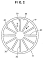
- FIG. 2 is a sectional view taken on line II-II of FIG. 1 .
- FIG. 3 is a sectional view taken on line III-III of FIG. 2 .
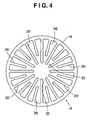
- FIG. 4 is a plan view showing another embodiment of an etched member.
- a support platform 2 is provided near the bottom of a cylindrical chamber 1 made of a metal (e.g., aluminum), and a substrate 3 is placed on the support platform 2.
- Temperature control means 6 equipped with a heater 4 and refrigerant flow-through means 5 is provided in the support platform 2 so that the support platform 2 is controlled to a predetermined temperature (for example, a temperature at which the substrate 3 is maintained at 100 to 200°C) by the temperature control means 6.
- An upper surface of the chamber 1 is an opening, which is closed with a disk-shaped ceiling board 7, a ceiling member made of an insulating material (for example, a ceramic).
- the interior of the chamber 1 closed with the ceiling board 7 is maintained at a predetermined pressure by a vacuum device 8.
- a nozzle 12 for supplying a source gas (a Cl 2 gas diluted with He or Ar to a chlorine concentration of ⁇ 50%, preferably about 10%) containing chlorine as a halogen to the interior of the chamber 1 is connected to a cylindrical portion of the chamber 1 above the support platform 2.
- the nozzle 12 is open toward the ceiling board 7, and is fed with the source gas via a flow controller 13.
- Fluorine (F), bromine (Br) or iodine (I) can also be applied as the halogen to be incorporated into the source gas.
- a plurality of the nozzles 12 can be provided in a circumferential direction such that the nozzles 12 are open in two or more different directions in the circumferential direction.
- the status of supply of the source gas (the status of generation of a plasma) can be controlled.
- the locations of the nozzles 12 are not limited to the illustrated embodiment; the nozzles 12 can be provided in a horizontal direction in an upper portion of the chamber 1, or can be provided in two stages, i.e., in an upper portion and a lower portion of the chamber 1.
- An etched member 18 made of a metal (Cu) is interposed between the opening at the upper surface of the chamber 1 and the ceiling board 7. As shown in FIGS. 1 and 2 , the etched member 18 is provided with a ring portion 19 fitted to the opening at the upper surface of the chamber 1.
- a plurality of (12 in the illustrated embodiment) protrusions 20, which extend close to the center in the diametrical direction of the chamber 1 and have the same width, are provided in the circumferential direction on the inner periphery of the ring portion 19.
- the protrusions 20 are integrally or removably attached to the ring portion 19. Notches (spaces) 35 formed between the protrusions 20 are present between the ceiling board 7 and the interior of the chamber 1.
- the ring portion 19 is earthed, and the plural protrusions 20 are electrically connected together and maintained at the same potential (same potential maintaining means).
- second protrusions 36 shorter in the diametrical direction than the protrusions 20 can be arranged between the protrusions 20.
- short protrusions can be arranged between the protrusion 20 and the second protrusion 36.
- the plasma antenna 9 is formed in a planar ring shape parallel to the surface of the ceiling board 7.
- the etched member 18 has the plurality of protrusions 20 provided in the circumferential direction on the inner periphery of the ring portion 19, and includes the notches (spaces) 35 formed between the protrusions 20.
- the protrusions 20 are arranged between the substrate and the ceiling member in a discontinuous state relative to the flowing direction of electricity in the plasma antenna 9.
- the source gas is supplied through the nozzles 12 to the interior of the chamber 1, and electromagnetic waves are shot from the plasma antenna 9 into the chamber 1.
- the Cl 2 gas is ionized to generate a Cl 2 gas plasma (source gas plasma) 14.
- the etched member 18, an electric conductor, is present below the plasma antenna 9.
- the Cl 2 gas plasma 14 occurs stably between the etched member 18 and the substrate 3, namely, below the etched member 18, under the following action:
- the etched member 18 When the etched member 18 is viewed from the substrate 3, therefore, there is no flow in a direction in which the flow A of electricity in the plasma antenna 9 is canceled out. Furthermore, the ring portion 19 is earthed, and the protrusions 20 are maintained at the same potential. Thus, even though the etched member 18, an electric conductor, exists, the electromagnetic wave is reliably thrown from the plasma antenna 9 into the chamber 1. Consequently, the Cl 2 gas plasma 14 is stably generated below the etched member 18.
- an etching reaction occurs in the etched member 18 made of copper to form a precursor (CU x Cl y ) 15.
- the etched member 18 is maintained by the Cl 2 gas plasma 14 at a predetermined temperature (e.g. , 200 to 400°C) higher than the temperature of the substrate 3.
- the precursor (Cu x Cl y ) 15 formed within the chamber 1 is transported toward the substrate 3 controlled to a temperature lower than the temperature of the etched member 18.
- the precursor (Cu x Cl y ) 15 transported toward the substrate 3 is converted into only Cu ions by a reduction reaction, and directed at the substrate 3 to form a thin Cu film 16 on the surface of the substrate 3.
- reaction in this case can be expressed by: 2Cu + Cl 2 ⁇ 2CuCl ⁇ 2Cu ⁇ + Cl 2 ⁇
- the gas that has not been involved in the reaction, and the etching product are exhausted through an exhaust port 17.
- the source gas has been described, with the Cl 2 gas diluted with, say, He or Ar taken as an example.
- the Cl 2 gas can be used alone, or an HCl gas can also be applied.
- an HCl gas plasma is formed as the source gas plasma, but the precursor formed by etching of the etched member 18 is Cu x Cl y .
- the source gas may be any gas containing chlorine, and a gas mixture of an HCl gas and a Cl 2 gas is also usable.
- the material for the etched member 18 is not limited to copper (Cu), but may be a halide-forming metal, preferably, a chloride-forming metal, such as Ag, Au, Pt, Ta, Ti or W.
- the precursor is a halide (chloride) of Ag, Au, Pt, Ta, Ti or W, and the thin firm formed on the surface of the substrate 3 is a thin film of Ag, Au, Pt, Ta, Ti or W.
- the metal film production apparatus uses the Cl 2 gas plasma (source gas plasma) 14.
- Cl 2 gas plasma source gas plasma
- the efficiency of the reaction markedly increases, and the film forming speed increases.
- the cost can be decreased sharply.
- the substrate 3 is controlled to a temperature lower than the temperature of the etched member 18 with the use of the temperature control means 6. Hence, smaller amounts of impurities, such as chlorine, can be left in the thin Cu film 16, so that a high quality thin Cu film 16 can be formed.
- the etched member 18 has the plurality of protrusions 20 provided in the circumferential direction on the inner periphery of the ring portion 19, and includes the notches (spaces) 35 formed between the protrusions 20.
- the induced currents generated in the etched member 18 flow in the same direction as the flowing direction of electricity in the plasma antenna 9, when viewed from the substrate 3. Therefore, even though the etched member 18, an electric conductor, exists below the plasma antenna 9, the electromagnetic waves are reliably thrown from the plasma antenna 9 into the chamber 1. Consequently, the Cl 2 gas plasma 14 can be stably generated below the etched member 18.
- a portion of the chamber 1, where the substrate 3 is disposed, may be partitioned off with a partition member made of an insulator below the nozzles 12. Many holes may be punched in the partition member, and the precursor (Cu x Cl y ) 15 formed by etching may be transported onto the substrate 3 through the resulting holes. That is, the interior of the chamber 1 can be divided into a site, where the Cl 2 gas plasma 14 is generated, and a site, where the substrate 3 is installed below the nozzles 12, by the partition member provided with the many holes. By so isolating the substrate 3 from the Cl 2 gas plasma 14, the substrate 3 is not exposed to the Cl 2 gas plasma 14, and thus is free from damage from the plasma.
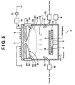
- FIG. 5 shows a schematic side view of the metal film production apparatus for performing the metal film production method according to the second embodiment of the present invention.
- the same members as the members illustrated in FIG. 1 are assigned the same numerals, and duplicate explanations are omitted.
- the metal film production apparatus is the metal film production apparatus shown in FIG. 1 provided that the shape of the etched member has been changed. That is, an etched member 21 made of a metal (Cu) is held between the opening at the upper surface of the chamber 1 and the ceiling board 7.
- the etched member 21 has a ring portion 22 fitted to the opening at the upper surface of the chamber 1, the ring portion 22 being in the form of a short cylinder having the same diameter as the diameter of the chamber 1.
- the thickness of the front end of the protrusion 23 is set at about a fourth to fifth of the thickness of the ring portion 22.
- the ring portion 22 is earthed, and the plural protrusions 23 are electrically connected together and maintained at the same potential (same potential maintaining means). Notches (spaces) are present between the protrusions 23 in the same manner as in the first embodiment.
- a sheath heater 24 is provided in the protrusion 23, and the temperature of the protrusion 23 is controlled by a thermocouple 25 (sensor) to a predetermined temperature higher than the temperature of the substrate 3 (the action of temperature control means).
- the sheath heater 24 and the thermocouple 25 may be provided in all of the protrusions 23, or may be provided in the protrusions 23 arranged alternately. Further, the sheath heater 24 and the thermocouple 25 can be provided in the ring portion 22.
- a source gas is supplied through the nozzles 12 to the interior of the chamber 1, and electromagnetic waves are shot from the plasma antenna 9 into the chamber 1.
- the Cl 2 gas is ionized to generate a Cl 2 gas plasma (source gas plasma) 14.
- the etched member 21, an electric conductor is present below the plasma antenna 9.
- the notches (space) are present, there is no flow in a direction in which the flow of electricity in the plasma antenna 9 is canceled out, when the etched member 21 is viewed from the substrate 3, as in the first embodiment.
- the ring portion 22 is earthed, and the protrusions 23 are maintained at the same potential.
- the etched member 21, an electric conductor exists, the electromagnetic waves are reliably thrown from the plasma antenna 9 into the chamber 1. Consequently, the Cl 2 gas plasma 14 is stably generated below the etched member 18.
- an etching reaction occurs in the etched member 21 made of copper to form a precursor (Cu x Cl y ) 15.
- the etched member 21 is maintained by the Cl 2 gas plasma 14 and the sheath heater 24 at a predetermined temperature (e.g., 200 to 400°C) higher than the temperature of the substrate 3.
- the precursor (Cu x Cl y ) 15 formed within the chamber 1 is transported toward the substrate 3 controlled to a temperature lower than the temperature of the etched member 21.
- the precursor (Cu x Cl y ) 15 transported toward the substrate 3 is converted into only Cu ions by a reduction reaction, and directed at the substrate 3 to form a thin Cu film 16 on the surface of the substrate 3.
- the etched member 21 is controlled by the sheath heater 24 and the thermocouple 25 to a predetermined temperature higher than the temperature of the substrate 3.
- This control coupled with the temperature control of the substrate 3 by the temperature control means 6, enables the temperature relationship between the etched member 21 and the substrate 3 to be controlled to temperature conditions optimal for the reduction reaction of the precursor (Cu x Cl y ) 15.
- the portion of the protrusion 23 beside the ring portion 22 is thick.
- the etching reaction can be performed efficiently by the effective use of the Cl 2 gas plasma 14 existent below.
- FIG. 6 shows a schematic side view of the metal film production apparatus for performing the metal film production method according to the third embodiment of the present invention.
- the same members as the members illustrated in FIG. 1 are assigned the same numerals, and duplicate explanations are omitted.
- the metal film production apparatus is the metal film production apparatus shown in FIG. 1 provided that the nozzles 12 and the flow controllers 13 at the lower portion of the chamber 1 are not provided.
- a gas passage 26 is formed in the center of the protrusion 20, and gas ejection holes 27 communicating with the gas passage 26 are formed at the front end of the protrusion 20 and at suitable positions in a lower area of the protrusion 20.
- a source gas is supplied from a flow controller 13 to the gas passage 26.
- the source gas is supplied to the interior of the chamber 1 through the gas ejection holes 27 of the protrusions 20, and electromagnetic waves are shot from the plasma antenna 9 into the chamber 1.
- the Cl 2 gas is ionized to generate a Cl 2 gas plasma (source gas plasma) 14.
- the etched member 18, an electric conductor is present below the plasma antenna 9.
- the ring portion 19 is earthed, and the protrusions 20 are maintained at the same potential.
- an etching reaction occurs in the etched member 18 made of copper to form a precursor (Cu x Cl y ) 15.
- the etched member 18 is maintained by the Cl 2 gas plasma 14 at a predetermined temperature (e.g., 200 to 400°C) higher than the temperature of the substrate 3.
- the precursor (Cu x Cl y ) 15 formed within the chamber 1 is transported toward the substrate 3 controlled to a temperature lower than the temperature of the etched member 18.
- the precursor (Cu x Cl y ) 15 transported toward the substrate 3 is converted into only Cu ions by a reduction reaction, and directed at the substrate 3 to form a thin Cu film 16 on the surface of the substrate 3.
- the source gas is supplied to the interior of the chamber 1 through the gas ejection holes 27 of the protrusions 20.
- the desired amount of the source gas can be supplied to the desired site. Consequently, it becomes possible to promote stabilization of the Cl 2 gas plasma 14 below the etched member 18.
- the etched member may comprise the protrusions 20 of the third embodiment provided with the gas passage 26 and the gas ejection holes 27, and the protrusions 23 of the second embodiment provided with the sheath heater 24 and the thermocouple 25, the protrusions 20 and the protrusions 23 being arranged alternately in the circumferential direction of the etched member. According to this configuration, it becomes possible to realize, at the same time, the optimal control of the temperature relationship between the substrate 3 and the etched member, and the promotion of stabilization of the Cl 2 gas plasma 14.
- FIG. 7 shows a schematic side view of the metal film production apparatus for performing the metal film production method according to the fourth embodiment of the present invention.
- the same members as the members illustrated in FIG. 1 are assigned the same numerals, and duplicate explanations are omitted.
- the metal film production apparatus according to the fourth embodiment shown in FIG. 7 is the metal film production apparatus shown in FIG. 1 provided that the shapes of the ceiling member, plasma antenna, and etched member are different. That is, a bowl-shaped (dome-shaped) ceiling member 28, which is made of an insulating material (ceramic or the like) and is convex outwardly, is fixed to an upper opening of the chamber 1.
- a bowl-shaped (dome-shaped) ceiling member 28 which is made of an insulating material (ceramic or the like) and is convex outwardly, is fixed to an upper opening of the chamber 1.
- An etched member 29 made of a metal (Cu) is held between the opening at the upper surface of the chamber 1 and the ceiling member 28.
- the etched member 29 has a ring portion 30 fitted on the opening at the upper surface of the chamber 1, and a plurality of protrusions 31, which extend close to the center in the diametrical direction of the chamber 1 and extend along the bowl-shaped inner surface of the ceiling member 28, are provided in the circumferential direction on the inner periphery of the ring portion 30.
- the ring portion 30 is earthed, and the plural protrusions 31 are electrically connected together and maintained at the same potential (same potential maintaining means).
- a sheath heater 24 and a thermocouple 25, as shown in the second embodiment, or a gas passage 26 and gas ejection holes 27, as shown in the third embodiment, may be provided in the protrusion 31 of the etched member 29.
- Many grooves or depressions may be formed in the underside of the protrusion 31 to create a discontinuous concavity in the surface.
- a plasma antenna 32 as an antenna member for converting the atmosphere inside the chamber 1 into a plasma, is provided in the surroundings above the ceiling member 28.
- the plasma antenna 32 is formed in a conical ring shape along the bowl-shaped surface of the ceiling member 28.
- a matching instrument 10 and a power source 11, as plasma generation means, are connected to the plasma antenna 32 to supply power.
- the etched member 29 has the plurality of protrusions 31 provided in the circumferential direction along the bowl-shaped surface of the ceiling member 28 on the inner periphery of the ring portion 30, and includes notches (spaces) formed between the protrusions 31.
- the protrusions 31 are arranged between a substrate 3 and the ceiling member 28 in a discontinuous state relative to the flowing direction of electricity in the plasma antenna 32.
- the source gas is supplied through the nozzle 12 to the interior of the chamber 1, and electromagnetic waves are shot from the plasma antenna 32 into the chamber 1.
- the Cl 2 gas is ionized to generate a Cl 2 gas plasma (source gas plasma) 14.
- the etched member 29, an electric conductor is present in a portion inside the chamber 1 opposed to the plasma antenna 32, with the ceiling member 28 being held between the plasma antenna 32 and the etched member 29.
- the notches (spaces) are present, there is no flow in a direction in which the flow of electricity in the plasma antenna 32 is canceled out, when the etched member 29 is viewed from the substrate 3, as in the first embodiment.
- the ring portion 30 is earthed, and the protrusions 31 are maintained at the same potential.
- the electromagnetic waves are reliably thrown from the plasma antenna 32 into the chamber 1. Consequently, the Cl 2 gas plasma 14 is stably generated inside of the etched member 29.
- an etching reaction occurs in the etched member 29 made of copper to form a precursor (Cu xC l y ) 15.
- the etched member 29 is maintained by the Cl 2 gas plasma 14 at a predetermined temperature (e.g., 200 to 400°C) higher than the temperature of the substrate 3.
- the precursor (Cu x Cl y ) 15 formed within the chamber 1 is transported toward the substrate 3 controlled to a temperature lower than the temperature of the etched member 29.
- the precursor (Cu x Cl y ) 15 transported toward the substrate 3 is converted into only Cu ions by a reduction reaction, and directed at the substrate 3 to form a thin Cu film 16 on the surface of the substrate 3.
- the ceiling member 28 is shaped like a bowl, and the plasma antenna 32 is shaped like a conical ring along the bowl shape of the ceiling member 28.
- the electromagnetic waves can be shot from around the ceiling member 28 to generate the Cl 2 gas plasma 14, thereby stabilizing the Cl 2 gas plasma 14 inwardly of the ceiling member 28.
- the uniformity of the Cl 2 gas plasma 14 inside of the chamber 1 can be achieved by the one power source.
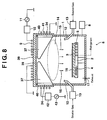
- FIG. 8 shows a schematic side view of the metal film production apparatus for performing the metal film production method according to the fifth embodiment of the present invention.
- the same members as the members illustrated in FIG. 1 are assigned the same numerals, and duplicate explanations are omitted.
- the metal film production apparatus is the metal film production apparatus shown in FIG. 1 provided that the shapes of the ceiling member, plasma antenna, and etched member are different. That is, a ceiling member 38 made of an insulating material (ceramic or the like) is fixed to an upper opening of the chamber 1.
- the ceiling member 38 is composed of a disk-shaped ceiling portion 39 and a tubular portion 40.
- the ceiling member may be composed of the ceiling portion 39 alone, and an upper cylindrical portion of the chamber 1 may be composed of an insulating material for use as the tubular portion.
- An etched member 33 made of a metal (Cu) is provided between the opening at the upper surface of the chamber 1 and the ceiling member 38.
- the etched member 33 has a tubular ring portion 34 disposed on the inner periphery of the tubular portion 40.
- a plurality of protrusions 37 which extend close to the center in the diametrical direction of the chamber 1, have the same width, and have a lower surface inclined upward and a thickness progressively decreased in an upward direction, are provided in the circumferential direction on the inner periphery of the ring portion 34.
- the ring portion 34 is earthed, and the plural protrusions 37 are electrically connected together and maintained at the same potential (same potential maintaining means).
- the sheath heater 24 and thermocouple 25, shown in the second embodiment, or the gas passage 26 and gas ejection holes 27, shown in the third embodiment, may be provided in the protrusion 37 of the etched member 33. Many grooves or depressions may be formed in the underside of the protrusion 37 to create a discontinuous concavity in the surface. By so doing, even if copper grows on the underside of the protrusion 37 from the precursor 15 formed by etching with the Cl 2 gas plasma 14, the copper does not grow just downward from the underside of the protrusion 37.
- the plasma antenna 9 is formed in a planar ring shape parallel to the surface of the ceiling portion 39.
- a coil antenna 41, as a coil antenna member for converting the atmosphere inside the chamber 1 into a plasma, is provided around the tubular portion 40.
- a second matching instrument 42 and a second power source 43, as plasma generation means, are connected to the coil antenna 41 to supply power.
- the etched member 33 has the plurality of protrusions 37 provided in the circumferential direction on the inner periphery of the ring portion 34, and includes notches (spaces) formed between the protrusions 37.
- the protrusions 37 are arranged between a substrate 3 and the ceiling member 38 in a discontinuous state relative to the flowing direction of electricity in the plasma antenna 9 and the coil antenna 41.
- the source gas is supplied through the nozzles 12 to the interior of the chamber 1, and electromagnetic waves are shot from the plasma antenna 9 and the coil antenna 41 into the chamber 1.
- the Cl 2 gas is ionized to generate a Cl 2 gas plasma (source gas plasma) 14.
- the etched member 33 an electric conductor, is present in a portion inside the chamber 1 opposed to the plasma antenna 9 and the coil antenna 41, with the ceiling member 38 being held between these antennas and the etched member 33.
- the notches (spaces) are present, there is no flow in a direction in which the flows of electricity in the plasma antenna 9 and the coil antenna 41 are canceled out, when the etched member 33 is viewed from the substrate 3, as in the first embodiment.
- the ring portion 34 is earthed, and the protrusions 37 are maintained at the same potential.
- the electromagnetic waves are reliably thrown from the plasma antenna 9 and the coil antenna 41 into the chamber 1. Consequently, the Cl 2 gas plasma 14 is stably generated inside of the etched member 33.
- an etching reaction occurs in the etched member 33 made of copper to form a precursor (Cu x Cl y ) 15.
- the etched member 33 is maintained by the Cl 2 gas plasma 14 at a predetermined temperature (e.g., 200 to 400°C) higher than the temperature of the substrate 3.
- the precursor (Cu x Cl y ) 15 formed within the chamber 1 is transported toward the substrate 3 controlled to a temperature lower than the temperature of the etched member 33.
- the precursor (C u xCl y ) 15 transported toward the substrate 3 is converted into only Cu ions by a reduction reaction, and directed at the substrate 3 to form a thin Cu film 16 on the surface of the substrate 3.
- the ceiling member 38 is composed of the ceiling portion 39 and the tubular portion 40, and the plasma antenna 9 and the coil antenna 41 are arranged outwardly of the ceiling member 38.
- the electromagnetic waves can be shot from around the ceiling member 38 to generate the Cl 2 gas plasma 14, thereby stabilizing the Cl 2 gas plasma 14 inwardly of the ceiling member 38.
- power is supplied individually to the plasma antenna 9 and the coil antenna 41.
- the state of the Cl 2 gas plasma 14 within the chamber 1 can be controlled to achieve the uniformity of the C1 2 gas plasma 14.
- the plasma antenna 9 and the coil antenna 41 can be integrated to perform power supply from a single power source.
Landscapes
- Chemical & Material Sciences (AREA)
- Engineering & Computer Science (AREA)
- General Chemical & Material Sciences (AREA)
- Chemical Kinetics & Catalysis (AREA)
- Materials Engineering (AREA)
- Mechanical Engineering (AREA)
- Metallurgy (AREA)
- Organic Chemistry (AREA)
- Analytical Chemistry (AREA)
- Plasma & Fusion (AREA)
- Physics & Mathematics (AREA)
- Electrochemistry (AREA)
- Chemical Vapour Deposition (AREA)
- Electrodes Of Semiconductors (AREA)
Abstract
Description
- The entire disclosure of Japanese Patent Application No.
2001-348315 filed on November 14, 2001 - This invention relates to a metal film production apparatus and a metal film production method which produce a metal film on the surface of a substrate by a vapor phase growth method.
- In preparing a metal film, such as a thin film of copper, by the vapor phase growth method, it has been common practice to use an organometallic complex of a liquid, for example, copper-hexafluoroacetylacetonato-trimethylvinylsilane, as a starting material, dissolve the solid starting material in a solvent, and vaporize the solution by use of a thermal reaction to form a film on a substrate.
- With the above-mentioned conventional technique, it has been difficult to increase the speed of film formation, because the film is formed with the use of a thermal reaction. Moreover, the metal complex as the starting material is expensive. In addition, hexafluoroacetylacetonato and trimethylvinylsilane accompanying copper remain as impurities in the thin film of copper, making it difficult to improve the quality of the film.
- The present invention has been accomplished in light of the circumstances described above. Its object is to provide a metal film production apparatus and a metal film production method which have a high film formation speed, which can use an inexpensive starting material, and which are free from impurities remaining in a film.
- According to an aspect of the present invention, there is provided an apparatus for forming a metal film as set out in
claim 1. - According to another aspect of the present invention, there is provided a method for forming a metal film as set out in
claim 6. - According to an aspect of the present invention, there is provided a metal film production apparatus, comprising a chamber accommodating a substrate and having an upper portion open; source gas supply means for supplying a source gas containing a halogen into the chamber; a ceiling member made of an insulating material for closing an opening of the upper portion of the chamber; an antenna member provided outwardly of the ceiling member and adapted to convert an atmosphere within the chamber into a plasma by supply of power; an etched member made of a metal and comprising a plurality of segments which are arranged between the substrate and the ceiling member in a discontinuous state relative to a flowing direction of electricity in the antenna member; plasma generation means which supplies power to the antenna member to generate on a substrate side of the etched member a flow of electricity in the same direction as the flowing direction of electricity in the antenna member, thereby converting the atmosphere within the chamber into a plasma and generating a source gas plasma so that the etched member is etched with the source gas plasma to form a precursor of a metal component contained in the etched member and the source gas; and temperature control means for controlling a temperature of the substrate to be lower than a temperature of the etched member to deposit the metal component of the precursor on the substrate as a film.
- Thus, the invention can provide a metal film production apparatus which has a high film formation speed, which can use an inexpensive starting material, and which can form a metal film free from impurities remaining therein. Furthermore, an induced current occurring in the etched member flows in the same direction as the direction of flow of electricity in the antenna member when viewed from the substrate. Even though the etched member, an electric conductor, exists opposite the antenna member, electromagnetic waves are reliably thrown from the antenna member into the chamber. Consequently, the source gas plasma can be stably generated, with the etched member being held between the antenna member and the substrate.
- According to another aspect of the present invention, there is provided a metal film production apparatus, comprising a cylindrical chamber accommodating a substrate and open at one end; a disk-shaped ceiling member made of an insulating material for closing an opening of the chamber; source gas supply means for supplying a source gas containing a halogen into the chamber; an antenna member of a planar ring shape provided outwardly of the ceiling member and adapted to convert an atmosphere within the chamber into a plasma by supply of power; an etched member made of a metal and comprising a plurality of segments which are arranged in a circumferential direction of the chamber and extend in a diametrical direction of the chamber between the substrate and the ceiling member, and which are in a discontinuous state relative to a flowing direction of electricity in the antenna member; plasma generation means which supplies power to the antenna member to generate on a substrate side of the etched member a flow of electricity in the same direction as the flowing direction of electricity in the antenna member, thereby converting the atmosphere within the chamber into a plasma and generating a source gas plasma so that the etched member is etched with the source gas plasma to form a precursor of a metal component contained in the etched member and the source gas; and temperature control means for controlling a temperature of the substrate to be lower than a temperature of the etched member to deposit the metal component of the precursor on the substrate as a film.
- Thus, the invention can provide a metal film production apparatus which has a high film formation speed, which can use an inexpensive starting material, and which can form a metal film free from impurities remaining therein. Furthermore, an induced current occurring in the etched member flows in the same direction as the direction of flow of electricity in the planar ring-shaped antenna member when viewed from the substrate. Even though the etched member, an electric conductor, exists opposite the planar ring-shaped antenna member, electromagnetic waves are reliably thrown from the antenna member into the chamber. Consequently, the source gas plasma can be stably generated, with the etched member being held between the antenna member and the substrate.
- According to still another aspect of the present invention, there is provided a metal film production apparatus, comprising a cylindrical chamber accommodating a substrate and open at one end; an outwardly curved convex ceiling member made of an insulating material for closing an opening of the chamber; source gas supply means for supplying a source gas containing a halogen into the chamber; an antenna member of a conical ring shape provided in surroundings outward of the ceiling member and adapted to convert an atmosphere within the chamber into a plasma by supply of power; an etched member made of a metal and comprising a plurality of segments which are arranged in a circumferential direction of the chamber and extend in a diametrical direction of the chamber between the substrate and the ceiling member, and which are in a discontinuous state relative to a flowing direction of electricity in the antenna member; plasma generation means which supplies power to the antenna member to generate on a substrate side of the etched member a flow of electricity in the same direction as the flowing direction of electricity in the antenna member, thereby converting the atmosphere within the chamber into a plasma and generating a source gas plasma so that the etched member is etched with the source gas plasma to form a precursor of a metal component contained in the etched member and the source gas; and temperature control means for controlling a temperature of the substrate to be lower than a temperature of the etched member to deposit the metal component of the precursor on the substrate as a film.
- Thus, the invention can provide a metal film production apparatus which has a high film formation speed, which can use an inexpensive starting material, and which can form a metal film free from impurities remaining therein. Furthermore, an induced current occurring in the etched member flows in the same direction as the direction of flow of electricity in the conical ring-shaped antenna member when viewed from the substrate. Even though the etched member, an electric conductor, exists opposite the conical ring-shaped antenna member, electromagnetic waves are reliably thrown from the antenna member into the chamber. Consequently, the source gas plasma can be stably generated inwardly of the etched member.
- According to a further aspect of the present invention, there is provided a metal film production apparatus, comprising a cylindrical chamber accommodating a substrate and open at one end; a disk-shaped ceiling member made of an insulating material for closing an opening of the chamber; a tubular portion made of an insulating material which is provided on the one end of the chamber; source gas supply means for supplying a source gas containing a halogen into the chamber; an antenna member of a planar ring shape provided outwardly of the ceiling member and adapted to convert an atmosphere within the chamber into a plasma by supply of power; a coil antenna member of a cylindrical coil shape provided around the tubular portion and adapted to convert the atmosphere within the chamber into a plasma by supply of power; an etched member made of a metal and comprising a plurality of segments which are arranged in a circumferential direction of the chamber and extend in a diametrical direction of the chamber between the substrate and the ceiling member, and which are in a discontinuous state relative to a flowing direction of electricity in the antenna member and the coil antenna member; plasma generation means which supplies power to the antenna member and the coil antenna member to generate on a side of the etched member opposite to the antenna member a flow of electricity in the same direction as the flowing direction of electricity in the antenna member, thereby converting the atmosphere within the chamber into a plasma and generating a source gas plasma so that the etched member is etched with the source gas plasma to form a precursor of a metal component contained in the etched member and the source gas; and temperature control means for controlling a temperature of the substrate to be lower than a temperature of the etched member to deposit the metal component of the precursor on the substrate as a film.
- Thus, the invention can provide a metal film production apparatus which has a high film formation speed, which can use an inexpensive starting material, and which can form a metal film free from impurities remaining therein. Furthermore, an induced current occurring in the etched member flows in the same direction as the direction of flow of electricity in the planar ring-shaped antenna member and the coil antenna member when viewed from the substrate. Even though the etched member, an electric conductor, exists opposite the planar ring-shaped antenna member and the coil antenna member, electromagnetic waves are reliably thrown from the antenna members into the chamber. Consequently, the source gas plasma can be stably generated inwardly of the etched member.
- The metal film production apparatus may further comprise same potential maintaining means for connecting the plurality of segments of the etched member electrically to impart the same potential thereto. In the metal film production apparatus, the temperature control means may be means provided in the etched member and adapted to keep the etched member at a higher temperature than the temperature of the substrate. In the metal film production apparatus, the source gas supply means may be a gas supply passage and gas ejection holes provided in the etched member, the gas ejection holes communicating with the gas supply passage.
- In the metal film production apparatus, a concave portion for creating a discontinuous concavity may be formed in a surface of the etched member facing the substrate. In the metal film production apparatus, the source gas containing the halogen may be a source gas containing chlorine. In the metal film production apparatus, the etched member may be made of copper to form CuxCly as the precursor. In the metal film production apparatus, the etched member may be made of tantalum, tungsten or titanium which is a halide-forming metal.
- According to a still further aspect of the present invention, there is provided a metal film production method involving converting an atmosphere within a chamber accommodating a substrate into a plasma by supply of power from an antenna member, comprising: disposing an etched member made of a metal and comprising a plurality of segments which are arranged in a discontinuous state relative to a flowing direction of electricity in the antenna member; supplying power to the antenna member to generate on a substrate side of the etched member a flow of electricity in the same direction as the flowing direction of electricity in the antenna member, thereby converting the atmosphere within the chamber into a plasma and generating a source gas plasma so that the etched member is etched with the source gas plasma to form a precursor of a metal component contained in the etched member and a source gas; and controlling a temperature of the substrate to be lower than a temperature of the etched member to deposit the metal component of the precursor on the substrate as a film.
- Thus, the invention can provide a metal film production method which has a high film formation speed, which can use an inexpensive starting material, and which can form a metal film free from impurities remaining therein. Furthermore, an induced current occurring in the etched member flows in the same direction as the direction of flow of electricity in the antenna member when viewed from the substrate. Even though the etched member, an electric conductor, exists opposite the antenna member, electromagnetic waves are reliably thrown from the antenna member into the chamber. Consequently, the source gas plasma can be stably generated, with the etched member being held between the antenna member and the substrate.
- In the metal film production method, the source gas containing the halogen may be a source gas containing chlorine. The etched member may be made of copper to form CuxCly as the precursor. The etched member may be made of tantalum, tungsten or titanium which is a halide-forming metal.
- The present invention will become more fully understood from the detailed description given hereinbelow and the accompanying drawings which are given by way of illustration only, and thus are not limitative of the present invention, and wherein:
-
FIG. 1 is a schematic side view of a metal film production apparatus for performing a metal film production method according to a first embodiment of the present invention; -
FIG. 2 is a sectional view taken on line II-II ofFIG. 1 ; -
FIG. 3 is a sectional view taken on line III-III ofFIG. 2 ; -
FIG. 4 is a plan view showing another embodiment of an etched member; -
FIG. 5 is a schematic side view of a metal film production apparatus for performing a metal film production method according to a second embodiment of the present invention; -
FIG. 6 is a schematic side view of a metal film production apparatus for performing a metal film production method according to a third embodiment of the present invention; -
FIG. 7 is a schematic side view of a metal film production apparatus for performing a metal film production method according to a fourth embodiment of the present invention; and -
FIG. 8 is a schematic side view of a metal film production apparatus for performing a metal film production method according to a fifth embodiment of the present invention. - The first embodiment of the metal film production apparatus and metal film production method of the present invention will be described with reference to
FIGS. 1 to 3 .FIG. 1 is a schematic side view of the metal film production apparatus for performing the metal film production method according to the first embodiment of the present invention.FIG. 2 is a sectional view taken on line II-II ofFIG. 1 .FIG. 3 is a sectional view taken on line III-III ofFIG. 2 .FIG. 4 is a plan view showing another embodiment of an etched member. - As shown in the drawings, a
support platform 2 is provided near the bottom of acylindrical chamber 1 made of a metal (e.g., aluminum), and asubstrate 3 is placed on thesupport platform 2. Temperature control means 6 equipped with aheater 4 and refrigerant flow-throughmeans 5 is provided in thesupport platform 2 so that thesupport platform 2 is controlled to a predetermined temperature (for example, a temperature at which thesubstrate 3 is maintained at 100 to 200°C) by the temperature control means 6. - An upper surface of the
chamber 1 is an opening, which is closed with a disk-shapedceiling board 7, a ceiling member made of an insulating material (for example, a ceramic). The interior of thechamber 1 closed with theceiling board 7 is maintained at a predetermined pressure by avacuum device 8. Anozzle 12 for supplying a source gas (a Cl2 gas diluted with He or Ar to a chlorine concentration of ≤ 50%, preferably about 10%) containing chlorine as a halogen to the interior of thechamber 1 is connected to a cylindrical portion of thechamber 1 above thesupport platform 2. Thenozzle 12 is open toward theceiling board 7, and is fed with the source gas via aflow controller 13. Fluorine (F), bromine (Br) or iodine (I) can also be applied as the halogen to be incorporated into the source gas. - A plurality of the
nozzles 12 can be provided in a circumferential direction such that thenozzles 12 are open in two or more different directions in the circumferential direction. By choosing thenozzles 12 different in the opening direction according to situations, the status of supply of the source gas (the status of generation of a plasma) can be controlled. The locations of thenozzles 12 are not limited to the illustrated embodiment; thenozzles 12 can be provided in a horizontal direction in an upper portion of thechamber 1, or can be provided in two stages, i.e., in an upper portion and a lower portion of thechamber 1. - An etched
member 18 made of a metal (Cu) is interposed between the opening at the upper surface of thechamber 1 and theceiling board 7. As shown inFIGS. 1 and2 , the etchedmember 18 is provided with aring portion 19 fitted to the opening at the upper surface of thechamber 1. A plurality of (12 in the illustrated embodiment)protrusions 20, which extend close to the center in the diametrical direction of thechamber 1 and have the same width, are provided in the circumferential direction on the inner periphery of thering portion 19. Theprotrusions 20 are integrally or removably attached to thering portion 19. Notches (spaces) 35 formed between theprotrusions 20 are present between theceiling board 7 and the interior of thechamber 1. Thering portion 19 is earthed, and theplural protrusions 20 are electrically connected together and maintained at the same potential (same potential maintaining means). - As shown in
FIG. 4 ,second protrusions 36 shorter in the diametrical direction than theprotrusions 20 can be arranged between theprotrusions 20. Moreover, short protrusions can be arranged between theprotrusion 20 and thesecond protrusion 36. By so doing, the area of copper, an object to be etched, can be secured, with an induced current being suppressed. - A
plasma antenna 9, as an antenna member for converting the atmosphere inside thechamber 1 into a plasma, is provided above theceiling board 7. Theplasma antenna 9 is formed in a planar ring shape parallel to the surface of theceiling board 7. A matchinginstrument 10 and apower source 11, as plasma generation means, are connected to theplasma antenna 9 to supply power. The etchedmember 18 has the plurality ofprotrusions 20 provided in the circumferential direction on the inner periphery of thering portion 19, and includes the notches (spaces) 35 formed between theprotrusions 20. Thus, theprotrusions 20 are arranged between the substrate and the ceiling member in a discontinuous state relative to the flowing direction of electricity in theplasma antenna 9. - With the above-described metal film production apparatus, the source gas is supplied through the
nozzles 12 to the interior of thechamber 1, and electromagnetic waves are shot from theplasma antenna 9 into thechamber 1. As a result, the Cl2 gas is ionized to generate a Cl2 gas plasma (source gas plasma) 14. The etchedmember 18, an electric conductor, is present below theplasma antenna 9. However, the Cl2 gas plasma 14 occurs stably between the etchedmember 18 and thesubstrate 3, namely, below the etchedmember 18, under the following action: - The action by which the Cl2 gas plasma 14 is generated below the etched
member 18 will be described. As shown inFIG. 3 , a flow A of electricity in theplasma antenna 9 of the planar ring shape crosses theprotrusions 20. At this time, an induced current B occurs on the surface of theprotrusion 20 opposed to theplasma antenna 9. Since the notches (spaces) 35 are present in the etchedmember 18, the induced current B flows onto the lower surface of eachprotrusion 20, forming a flow a in the same direction as the flow A of electricity in the plasma antenna 9 (Faraday shield). - When the etched
member 18 is viewed from thesubstrate 3, therefore, there is no flow in a direction in which the flow A of electricity in theplasma antenna 9 is canceled out. Furthermore, thering portion 19 is earthed, and theprotrusions 20 are maintained at the same potential. Thus, even though the etchedmember 18, an electric conductor, exists, the electromagnetic wave is reliably thrown from theplasma antenna 9 into thechamber 1. Consequently, the Cl2 gas plasma 14 is stably generated below the etchedmember 18. - It is also possible to eliminate instability of the plasma due to differences in potential not by connecting the
protrusions 20 to thering potion 19, but by controlling the supply of the source gas. - Owing to the Cl2 gas plasma 14, an etching reaction occurs in the etched
member 18 made of copper to form a precursor (CUxCly) 15. At this time, the etchedmember 18 is maintained by the Cl2 gas plasma 14 at a predetermined temperature (e.g. , 200 to 400°C) higher than the temperature of thesubstrate 3. The precursor (CuxCly) 15 formed within thechamber 1 is transported toward thesubstrate 3 controlled to a temperature lower than the temperature of the etchedmember 18. The precursor (CuxCly) 15 transported toward thesubstrate 3 is converted into only Cu ions by a reduction reaction, and directed at thesubstrate 3 to form athin Cu film 16 on the surface of thesubstrate 3. - The reaction in this case can be expressed by:
2Cu + Cl2 → 2CuCl → 2Cu↓ + Cl2↑
- The gas that has not been involved in the reaction, and the etching product are exhausted through an
exhaust port 17. - The source gas has been described, with the Cl2 gas diluted with, say, He or Ar taken as an example. However, the Cl2 gas can be used alone, or an HCl gas can also be applied. When the HCl gas is applied, an HCl gas plasma is formed as the source gas plasma, but the precursor formed by etching of the etched
member 18 is CuxCly. Thus, the source gas may be any gas containing chlorine, and a gas mixture of an HCl gas and a Cl2 gas is also usable. The material for the etchedmember 18 is not limited to copper (Cu), but may be a halide-forming metal, preferably, a chloride-forming metal, such as Ag, Au, Pt, Ta, Ti or W. In this case, the precursor is a halide (chloride) of Ag, Au, Pt, Ta, Ti or W, and the thin firm formed on the surface of thesubstrate 3 is a thin film of Ag, Au, Pt, Ta, Ti or W. - The metal film production apparatus having the above-described features uses the Cl2 gas plasma (source gas plasma) 14. Thus, the efficiency of the reaction markedly increases, and the film forming speed increases. Also, since a Cl2 gas is used as the source gas, the cost can be decreased sharply. Moreover, the
substrate 3 is controlled to a temperature lower than the temperature of the etchedmember 18 with the use of the temperature control means 6. Hence, smaller amounts of impurities, such as chlorine, can be left in thethin Cu film 16, so that a high qualitythin Cu film 16 can be formed. - In addition, the etched
member 18 has the plurality ofprotrusions 20 provided in the circumferential direction on the inner periphery of thering portion 19, and includes the notches (spaces) 35 formed between theprotrusions 20. Thus, the induced currents generated in the etchedmember 18 flow in the same direction as the flowing direction of electricity in theplasma antenna 9, when viewed from thesubstrate 3. Therefore, even though the etchedmember 18, an electric conductor, exists below theplasma antenna 9, the electromagnetic waves are reliably thrown from theplasma antenna 9 into thechamber 1. Consequently, the Cl2 gas plasma 14 can be stably generated below the etchedmember 18. - Many grooves or depressions may be formed in the underside of the etched member 18 (protrusion 20) to create a discontinuous concavity in the surface. By so doing, even if copper grows on the underside of the
protrusion 20 from theprecursor 15 formed by etching with the Cl2 gas plasma 14, the copper does not grow just downward from the underside of theprotrusion 20. - A portion of the
chamber 1, where thesubstrate 3 is disposed, may be partitioned off with a partition member made of an insulator below thenozzles 12. Many holes may be punched in the partition member, and the precursor (CuxCly) 15 formed by etching may be transported onto thesubstrate 3 through the resulting holes. That is, the interior of thechamber 1 can be divided into a site, where the Cl2 gas plasma 14 is generated, and a site, where thesubstrate 3 is installed below thenozzles 12, by the partition member provided with the many holes. By so isolating thesubstrate 3 from the Cl2 gas plasma 14, thesubstrate 3 is not exposed to the Cl2 gas plasma 14, and thus is free from damage from the plasma. - The metal film production apparatus and metal film production method according to the second embodiment of the present invention will be described with reference to
FIG. 5. FIG. 5 shows a schematic side view of the metal film production apparatus for performing the metal film production method according to the second embodiment of the present invention. The same members as the members illustrated inFIG. 1 are assigned the same numerals, and duplicate explanations are omitted. - The metal film production apparatus according to the second embodiment shown in
FIG. 5 is the metal film production apparatus shown inFIG. 1 provided that the shape of the etched member has been changed. That is, an etchedmember 21 made of a metal (Cu) is held between the opening at the upper surface of thechamber 1 and theceiling board 7. The etchedmember 21 has aring portion 22 fitted to the opening at the upper surface of thechamber 1, thering portion 22 being in the form of a short cylinder having the same diameter as the diameter of thechamber 1. - A plurality of
protrusions 23, which extend close to the center in the diametrical direction of thechamber 1, have the same width, and have a lower surface inclined upward and a thickness progressively decreased in an upward direction, are provided in the circumferential direction on the inner periphery of thering portion 22. For example, the thickness of the front end of theprotrusion 23 is set at about a fourth to fifth of the thickness of thering portion 22. Thering portion 22 is earthed, and theplural protrusions 23 are electrically connected together and maintained at the same potential (same potential maintaining means). Notches (spaces) are present between theprotrusions 23 in the same manner as in the first embodiment. - A
sheath heater 24 is provided in theprotrusion 23, and the temperature of theprotrusion 23 is controlled by a thermocouple 25 (sensor) to a predetermined temperature higher than the temperature of the substrate 3 (the action of temperature control means). Thesheath heater 24 and thethermocouple 25 may be provided in all of theprotrusions 23, or may be provided in theprotrusions 23 arranged alternately. Further, thesheath heater 24 and thethermocouple 25 can be provided in thering portion 22. - With the above-described metal film production apparatus, a source gas is supplied through the
nozzles 12 to the interior of thechamber 1, and electromagnetic waves are shot from theplasma antenna 9 into thechamber 1. As a result, the Cl2 gas is ionized to generate a Cl2 gas plasma (source gas plasma) 14. The etchedmember 21, an electric conductor, is present below theplasma antenna 9. However, since the notches (space) are present, there is no flow in a direction in which the flow of electricity in theplasma antenna 9 is canceled out, when the etchedmember 21 is viewed from thesubstrate 3, as in the first embodiment. Furthermore, thering portion 22 is earthed, and theprotrusions 23 are maintained at the same potential. Thus, even though the etchedmember 21, an electric conductor, exists, the electromagnetic waves are reliably thrown from theplasma antenna 9 into thechamber 1. Consequently, the Cl2 gas plasma 14 is stably generated below the etchedmember 18. - Owing to the Cl2 gas plasma 14, an etching reaction occurs in the etched
member 21 made of copper to form a precursor (CuxCly) 15. At this time, the etchedmember 21 is maintained by the Cl2 gas plasma 14 and thesheath heater 24 at a predetermined temperature (e.g., 200 to 400°C) higher than the temperature of thesubstrate 3. The precursor (CuxCly) 15 formed within thechamber 1 is transported toward thesubstrate 3 controlled to a temperature lower than the temperature of the etchedmember 21. The precursor (CuxCly) 15 transported toward thesubstrate 3 is converted into only Cu ions by a reduction reaction, and directed at thesubstrate 3 to form athin Cu film 16 on the surface of thesubstrate 3. - In the metal film production apparatus having the above features, the etched
member 21 is controlled by thesheath heater 24 and thethermocouple 25 to a predetermined temperature higher than the temperature of thesubstrate 3. This control, coupled with the temperature control of thesubstrate 3 by the temperature control means 6, enables the temperature relationship between the etchedmember 21 and thesubstrate 3 to be controlled to temperature conditions optimal for the reduction reaction of the precursor (CuxCly) 15. Moreover, the portion of theprotrusion 23 beside thering portion 22 is thick. Thus, the etching reaction can be performed efficiently by the effective use of the Cl2 gas plasma 14 existent below. - Many grooves or depressions may be formed in the underside of the etched member 21 (protrusion 23) to create a discontinuous cavity in the surface. By so doing, even if copper grows on the underside of the
protrusion 23 from theprecursor 15 formed by etching with the Cl2 gas plasma 14, the copper does not grow just downward from the underside of theprotrusion 23. - The metal film production apparatus and metal film production method according to the third embodiment of the present invention will be described with reference to
FIG. 6. FIG. 6 shows a schematic side view of the metal film production apparatus for performing the metal film production method according to the third embodiment of the present invention. The same members as the members illustrated inFIG. 1 are assigned the same numerals, and duplicate explanations are omitted. - The metal film production apparatus according to the third embodiment shown in
FIG. 6 is the metal film production apparatus shown inFIG. 1 provided that thenozzles 12 and theflow controllers 13 at the lower portion of thechamber 1 are not provided. Agas passage 26 is formed in the center of theprotrusion 20, and gas ejection holes 27 communicating with thegas passage 26 are formed at the front end of theprotrusion 20 and at suitable positions in a lower area of theprotrusion 20. A source gas is supplied from aflow controller 13 to thegas passage 26. - With the above-described metal film production apparatus, the source gas is supplied to the interior of the
chamber 1 through the gas ejection holes 27 of theprotrusions 20, and electromagnetic waves are shot from theplasma antenna 9 into thechamber 1. As a result, the Cl2 gas is ionized to generate a Cl2 gas plasma (source gas plasma) 14. The etchedmember 18, an electric conductor, is present below theplasma antenna 9. However, there is no flow in a direction in which the flow of electricity in theplasma antenna 9 is canceled out, when the etchedmember 18 is viewed from thesubstrate 3, as in the first embodiment. Furthermore, thering portion 19 is earthed, and theprotrusions 20 are maintained at the same potential. Thus, even though the etchedmember 18, an electric conductor, exists, the electromagnetic waves are reliably thrown from theplasma antenna 9 into thechamber 1. Consequently, the Cl2 gas plasma 14 is stably generated below the etchedmember 18. - Owing to the Cl2 gas plasma 14, an etching reaction occurs in the etched
member 18 made of copper to form a precursor (CuxCly) 15. At this time, the etchedmember 18 is maintained by the Cl2 gas plasma 14 at a predetermined temperature (e.g., 200 to 400°C) higher than the temperature of thesubstrate 3. The precursor (CuxCly) 15 formed within thechamber 1 is transported toward thesubstrate 3 controlled to a temperature lower than the temperature of the etchedmember 18. The precursor (CuxCly) 15 transported toward thesubstrate 3 is converted into only Cu ions by a reduction reaction, and directed at thesubstrate 3 to form athin Cu film 16 on the surface of thesubstrate 3. - In the metal film production apparatus having the above features, the source gas is supplied to the interior of the
chamber 1 through the gas ejection holes 27 of theprotrusions 20. Thus, separately installed nozzles are unnecessary, and the desired amount of the source gas can be supplied to the desired site. Consequently, it becomes possible to promote stabilization of the Cl2 gas plasma 14 below the etchedmember 18. - In addition, the etched member may comprise the
protrusions 20 of the third embodiment provided with thegas passage 26 and the gas ejection holes 27, and theprotrusions 23 of the second embodiment provided with thesheath heater 24 and thethermocouple 25, theprotrusions 20 and theprotrusions 23 being arranged alternately in the circumferential direction of the etched member. According to this configuration, it becomes possible to realize, at the same time, the optimal control of the temperature relationship between thesubstrate 3 and the etched member, and the promotion of stabilization of the Cl2 gas plasma 14. - The metal film production apparatus and metal film production method according to the fourth embodiment of the present invention will be described with reference to
FIG. 7. FIG. 7 shows a schematic side view of the metal film production apparatus for performing the metal film production method according to the fourth embodiment of the present invention. The same members as the members illustrated inFIG. 1 are assigned the same numerals, and duplicate explanations are omitted. - The metal film production apparatus according to the fourth embodiment shown in
FIG. 7 is the metal film production apparatus shown inFIG. 1 provided that the shapes of the ceiling member, plasma antenna, and etched member are different. That is, a bowl-shaped (dome-shaped)ceiling member 28, which is made of an insulating material (ceramic or the like) and is convex outwardly, is fixed to an upper opening of thechamber 1. - An etched
member 29 made of a metal (Cu) is held between the opening at the upper surface of thechamber 1 and theceiling member 28. The etchedmember 29 has aring portion 30 fitted on the opening at the upper surface of thechamber 1, and a plurality ofprotrusions 31, which extend close to the center in the diametrical direction of thechamber 1 and extend along the bowl-shaped inner surface of theceiling member 28, are provided in the circumferential direction on the inner periphery of thering portion 30. Thering portion 30 is earthed, and theplural protrusions 31 are electrically connected together and maintained at the same potential (same potential maintaining means). - A
sheath heater 24 and athermocouple 25, as shown in the second embodiment, or agas passage 26 and gas ejection holes 27, as shown in the third embodiment, may be provided in theprotrusion 31 of the etchedmember 29. Many grooves or depressions may be formed in the underside of theprotrusion 31 to create a discontinuous concavity in the surface. By so doing, even if copper grows on the underside of theprotrusion 31 from theprecursor 15 formed by etching with the Cl2 gas plasma 14, the copper does not grow just downward from the underside of theprotrusion 31. - A
plasma antenna 32, as an antenna member for converting the atmosphere inside thechamber 1 into a plasma, is provided in the surroundings above theceiling member 28. Theplasma antenna 32 is formed in a conical ring shape along the bowl-shaped surface of theceiling member 28. A matchinginstrument 10 and apower source 11, as plasma generation means, are connected to theplasma antenna 32 to supply power. The etchedmember 29 has the plurality ofprotrusions 31 provided in the circumferential direction along the bowl-shaped surface of theceiling member 28 on the inner periphery of thering portion 30, and includes notches (spaces) formed between theprotrusions 31. Thus, theprotrusions 31 are arranged between asubstrate 3 and theceiling member 28 in a discontinuous state relative to the flowing direction of electricity in theplasma antenna 32. - With the above-described metal film production apparatus, the source gas is supplied through the
nozzle 12 to the interior of thechamber 1, and electromagnetic waves are shot from theplasma antenna 32 into thechamber 1. As a result, the Cl2 gas is ionized to generate a Cl2 gas plasma (source gas plasma) 14. The etchedmember 29, an electric conductor, is present in a portion inside thechamber 1 opposed to theplasma antenna 32, with theceiling member 28 being held between theplasma antenna 32 and the etchedmember 29. However, since the notches (spaces) are present, there is no flow in a direction in which the flow of electricity in theplasma antenna 32 is canceled out, when the etchedmember 29 is viewed from thesubstrate 3, as in the first embodiment. Furthermore, thering portion 30 is earthed, and theprotrusions 31 are maintained at the same potential. Thus, even though the etchedmember 29, an electric conductor, exists, the electromagnetic waves are reliably thrown from theplasma antenna 32 into thechamber 1. Consequently, the Cl2 gas plasma 14 is stably generated inside of the etchedmember 29. - Owing to the Cl2 gas plasma 14, an etching reaction occurs in the etched
member 29 made of copper to form a precursor (CuxCly) 15. At this time, the etchedmember 29 is maintained by the Cl2 gas plasma 14 at a predetermined temperature (e.g., 200 to 400°C) higher than the temperature of thesubstrate 3. The precursor (CuxCly) 15 formed within thechamber 1 is transported toward thesubstrate 3 controlled to a temperature lower than the temperature of the etchedmember 29. The precursor (CuxCly) 15 transported toward thesubstrate 3 is converted into only Cu ions by a reduction reaction, and directed at thesubstrate 3 to form athin Cu film 16 on the surface of thesubstrate 3. - In the metal film production apparatus having the above features, the
ceiling member 28 is shaped like a bowl, and theplasma antenna 32 is shaped like a conical ring along the bowl shape of theceiling member 28. Thus, the electromagnetic waves can be shot from around theceiling member 28 to generate the Cl2 gas plasma 14, thereby stabilizing the Cl2 gas plasma 14 inwardly of theceiling member 28. Hence, the uniformity of the Cl2 gas plasma 14 inside of thechamber 1 can be achieved by the one power source. - The metal film production apparatus and metal film production method according to the fifth embodiment of the present invention will be described with reference to
FIG. 8. FIG. 8 shows a schematic side view of the metal film production apparatus for performing the metal film production method according to the fifth embodiment of the present invention. The same members as the members illustrated inFIG. 1 are assigned the same numerals, and duplicate explanations are omitted. - The metal film production apparatus according to the fifth embodiment shown in
FIG. 8 is the metal film production apparatus shown inFIG. 1 provided that the shapes of the ceiling member, plasma antenna, and etched member are different. That is, aceiling member 38 made of an insulating material (ceramic or the like) is fixed to an upper opening of thechamber 1. Theceiling member 38 is composed of a disk-shapedceiling portion 39 and atubular portion 40. The ceiling member may be composed of theceiling portion 39 alone, and an upper cylindrical portion of thechamber 1 may be composed of an insulating material for use as the tubular portion. - An etched member 33 made of a metal (Cu) is provided between the opening at the upper surface of the
chamber 1 and theceiling member 38. The etched member 33 has atubular ring portion 34 disposed on the inner periphery of thetubular portion 40. A plurality ofprotrusions 37, which extend close to the center in the diametrical direction of thechamber 1, have the same width, and have a lower surface inclined upward and a thickness progressively decreased in an upward direction, are provided in the circumferential direction on the inner periphery of thering portion 34. Thering portion 34 is earthed, and theplural protrusions 37 are electrically connected together and maintained at the same potential (same potential maintaining means). - The
sheath heater 24 andthermocouple 25, shown in the second embodiment, or thegas passage 26 and gas ejection holes 27, shown in the third embodiment, may be provided in theprotrusion 37 of the etched member 33. Many grooves or depressions may be formed in the underside of theprotrusion 37 to create a discontinuous concavity in the surface. By so doing, even if copper grows on the underside of theprotrusion 37 from theprecursor 15 formed by etching with the Cl2 gas plasma 14, the copper does not grow just downward from the underside of theprotrusion 37. - A
plasma antenna 9, as an antenna member for converting the atmosphere inside thechamber 1 into a plasma, is provided above theceiling portion 39 of theceiling member 38. Theplasma antenna 9 is formed in a planar ring shape parallel to the surface of theceiling portion 39. A matchinginstrument 10 and apower source 11, as plasma generation means, are connected to theplasma antenna 9 to supply power. Acoil antenna 41, as a coil antenna member for converting the atmosphere inside thechamber 1 into a plasma, is provided around thetubular portion 40. Asecond matching instrument 42 and asecond power source 43, as plasma generation means, are connected to thecoil antenna 41 to supply power. - The etched member 33 has the plurality of
protrusions 37 provided in the circumferential direction on the inner periphery of thering portion 34, and includes notches (spaces) formed between theprotrusions 37. Thus, theprotrusions 37 are arranged between asubstrate 3 and theceiling member 38 in a discontinuous state relative to the flowing direction of electricity in theplasma antenna 9 and thecoil antenna 41. - With the above-described metal film production apparatus, the source gas is supplied through the
nozzles 12 to the interior of thechamber 1, and electromagnetic waves are shot from theplasma antenna 9 and thecoil antenna 41 into thechamber 1. As a result, the Cl2 gas is ionized to generate a Cl2 gas plasma (source gas plasma) 14. The etched member 33, an electric conductor, is present in a portion inside thechamber 1 opposed to theplasma antenna 9 and thecoil antenna 41, with theceiling member 38 being held between these antennas and the etched member 33. However, since the notches (spaces) are present, there is no flow in a direction in which the flows of electricity in theplasma antenna 9 and thecoil antenna 41 are canceled out, when the etched member 33 is viewed from thesubstrate 3, as in the first embodiment. Furthermore, thering portion 34 is earthed, and theprotrusions 37 are maintained at the same potential. Thus, even though the etched member 33, an electric conductor, exists, the electromagnetic waves are reliably thrown from theplasma antenna 9 and thecoil antenna 41 into thechamber 1. Consequently, the Cl2 gas plasma 14 is stably generated inside of the etched member 33. - Owing to the Cl2 gas plasma 14, an etching reaction occurs in the etched member 33 made of copper to form a precursor (CuxCly) 15. At this time, the etched member 33 is maintained by the Cl2 gas plasma 14 at a predetermined temperature (e.g., 200 to 400°C) higher than the temperature of the
substrate 3. The precursor (CuxCly) 15 formed within thechamber 1 is transported toward thesubstrate 3 controlled to a temperature lower than the temperature of the etched member 33. The precursor (CuxCly) 15 transported toward thesubstrate 3 is converted into only Cu ions by a reduction reaction, and directed at thesubstrate 3 to form athin Cu film 16 on the surface of thesubstrate 3. - In the metal film production apparatus having the above features, the
ceiling member 38 is composed of theceiling portion 39 and thetubular portion 40, and theplasma antenna 9 and thecoil antenna 41 are arranged outwardly of theceiling member 38. Thus, the electromagnetic waves can be shot from around theceiling member 38 to generate the Cl2 gas plasma 14, thereby stabilizing the Cl2 gas plasma 14 inwardly of theceiling member 38. Furthermore, power is supplied individually to theplasma antenna 9 and thecoil antenna 41. Hence, the state of the Cl2 gas plasma 14 within thechamber 1 can be controlled to achieve the uniformity of the C12 gas plasma 14. Theplasma antenna 9 and thecoil antenna 41 can be integrated to perform power supply from a single power source. - While the present invention has been described by the foregoing embodiments, it is to be understood that the invention is not limited thereby, but may be varied in many other ways. For example, the embodiments have been described, with the etched member being disposed on the ceiling side of the chamber, and the substrate being disposed on the lower side of the chamber. However, the positions of the etched member and the substrate in the vertical direction may be reversed, and in some cases, the etched member and the substrate may be arranged in the right-and-left direction.
Such variations are not to be regarded as a departure from the spirit and scope of the invention, and all such modifications as would be obvious to one skilled in the art are intended to be included within the scope of the appended claims.
Claims (15)
- An apparatus for forming a metal film, comprising:a reaction vessel configured and positioned to house a substrate and a plate made of metal;an inlet configured and positioned to feed a gas comprising a halogen into a space between the substrate and the plate within the reaction vessel;an outlet configured and positioned to exhaust said reaction vessel; anda plasma generator configured and positioned to generate a plasma containing the halogen, to etch said plate by the plasma, thereby reacting the metal of said plate with the halogen, and forming a reaction product comprising the metal and the halogen.
- An apparatus according to claim 1, wherein said gas comprises a halogen gas and He or Ar.
- An apparatus according to claim 2, wherein said halogen gas comprises a chlorine gas.
- An apparatus according to claim 1, wherein said metal comprises Cu, Ag, Au, Pt, Ta, Ti or W.
- An apparatus according to claim 1, further comprising a heater configured and positioned to heat said substrate at a temperature controlled to deposit the metal on said substrate.
- A method for forming a metal film, comprising the steps:housing a substrate and a plate made of metal in a reaction vessel;feeding a gas comprising a halogen in a space between the substrate and the plate within the reaction vessel;exhausting an atmosphere of said reaction vessel; andgenerating a plasma containing the halogen, to etch said plate by the plasma, thereby reacting the metal of said plate with the halogen, and forming a reaction product comprising the metal and the halogen.
- A method according to claim 6, wherein said gas comprises a halogen gas and He or Ar.
- A method according to claim 6, wherein said halogen gas comprises a chlorine gas.
- A method according to claim 6, wherein said metal comprises Cu, Ag, Au, Pt, Ta, Ti or W.
- A method according to claim 6, further comprising a step of heating said substrate at a temperature controlled to deposit the metal on said substrate.
- A metal film production apparatus, comprising:a chamber accommodating a substrate and having an upper portion open;source gas supply means for supplying a source gas containing a halogen into the chamber;a ceiling member made of an insulating material for closing an opening of the upper portion of the chamber;an antenna member provided outwardly of the ceiling member and adapted to convert an atmosphere within the chamber into a plasma by supply of power;an etched member made of a metal and comprising a plurality of segments which are arranged between the substrate and the ceiling member in a discontinuous state relative to a flowing direction of electricity in the antenna member;plasma generation means which supplies power to the antenna member to generate on a substrate side of the etched member a flow of electricity in the same direction as the flowing direction of electricity in the antenna member, thereby converting the atmosphere within the chamber into a plasma and generating a source gas plasma so that the etched member is etched with the source gas plasma to form a precursor of a metal component contained in the etched member and the source gas; andtemperature control means for controlling a temperature of the substrate to be lower than a temperature of the etched member to deposit the metal component of the precursor on the substrate as a film.
- A metal film production apparatus, comprising:a cylindrical chamber accommodating a substrate and open at one end;a disk-shaped ceiling member made of an insulating material for closing an opening of the chamber;source gas supply means for supplying a source gas containing a halogen into the chamber;an antenna member of a planar ring shape provided outwardly of the ceiling member and adapted to convert an atmosphere within the chamber into a plasma by supply of power;an etched member made of a metal and comprising a plurality of segments which are arranged in a circumferential direction of the chamber and extend in a diametrical direction of the chamber between the substrate and the ceiling member, and which are in a discontinuous state relative to a flowing direction of electricity in the antenna member;plasma generation means which supplies power to the antenna member to generate on a substrate side of the etched member a flow of electricity in the same direction as the flowing direction of electricity in the antenna member, thereby converting the atmosphere within the chamber into a plasma and generating a source gas plasma so that the etched member is etched with the source gas plasma to form a precursor of a metal component contained in the etched member and the source gas; andtemperature control means for controlling a temperature of the substrate to be lower than a temperature of the etched member to deposit the metal component of the precursor on the substrate as a film.
- A metal film production apparatus, comprising:a cylindrical chamber accommodating a substrate and open at one end;an outwardly curved convex ceiling member made of an insulating material for closing an opening of the chamber;source gas supply means for supplying a source gas containing a halogen into the chamber;an antenna member of a conical ring shape provided in surroundings outward of the ceiling member and adapted to convert an atmosphere within the chamber into a plasma by supply of power;an etched member made of a metal and comprising a plurality of segments which are arranged in a circumferential direction of the chamber and extend in a diametrical direction of the chamber between the substrate and the ceiling member, and which are in a discontinuous state relative to a flowing direction of electricity in the antenna member;plasma generation means which supplies power to the antenna member to generate on a substrate side of the etched member a flow of electricity in the same direction as the flowing direction of electricity in the antenna member, thereby converting the atmosphere within the chamber into a plasma and generating a source gas plasma so that the etched member is etched with the source gas plasma to form a precursor of a metal component contained in the etched member and the source gas; andtemperature control means for controlling a temperature of the substrate to be lower than a temperature of the etched member to deposit the metal component of the precursor on the substrate as a film.
- A metal film production apparatus, comprising:a cylindrical chamber accommodating a substrate and open at one end;a disk-shaped ceiling member made of an insulating material for closing an opening of the chamber;a tubular portion made of an insulating material which is provided on the one end of the chamber;source gas supply means for supplying a source gas containing a halogen into the chamber;an antenna member of a planar ring shape provided outwardly of the ceiling member and adapted to convert an atmosphere within the chamber into a plasma by supply of power;a coil antenna member of a cylindrical coil shape provided around the tubular portion and adapted to convert the atmosphere within the chamber into a plasma by supply of power;an etched member made of a metal and comprising a plurality of segments which are arranged in a circumferential direction of the chamber and extend in a diametrical direction of the chamber between the substrate and the ceiling member, and which are in a discontinuous state relative to a flowing direction of electricity in the antenna member and the coil antenna member;plasma generation means which supplies power to the antenna member and the coil antenna member to generate on a side of the etched member opposite to the antenna member a flow of electricity in the same direction as the flowing direction of electricity in the antenna member, thereby converting the atmosphere within the chamber into a plasma and generating a source gas plasma so that the etched member is etched with the source gas plasma to form a precursor of a metal component contained in the etched member and the source gas; andtemperature control means for controlling a temperature of the substrate to be lower than a temperature of the etched member to deposit the metal component of the precursor on the substrate as a film.
- A metal film production method involving converting an atmosphere within a chamber accommodating a substrate into a plasma by supply of power from an antenna member, comprising:disposing an etched member made of a metal and comprising a plurality of segments which are arranged in a discontinuous state relative to a flowing direction of electricity in the antenna member;supplying power to the antenna member to generate on a substrate side of the etched member a flow of electricity in the same direction as the flowing direction of electricity in the antenna member, thereby converting the atmosphere within the chamber into a plasma and generating a source gas plasma so that the etched member is etched with the source gas plasma to form a precursor of a metal component contained in the etched member and a source gas; andcontrolling a temperature of the substrate to be lower than a temperature of the etched member to deposit the metal component of the precursor on the substrate as a film.
Applications Claiming Priority (2)
| Application Number | Priority Date | Filing Date | Title |
|---|---|---|---|
| JP2001348315A JP3727878B2 (en) | 2001-11-14 | 2001-11-14 | Metal film production equipment |
| EP02024599A EP1313127B1 (en) | 2001-11-14 | 2002-11-05 | Metal film production apparatus |
Related Parent Applications (2)
| Application Number | Title | Priority Date | Filing Date |
|---|---|---|---|
| EP02024599.9 Division | 2002-11-05 | ||
| EP02024599A Division EP1313127B1 (en) | 2001-11-14 | 2002-11-05 | Metal film production apparatus |
Publications (2)
| Publication Number | Publication Date |
|---|---|
| EP2051282A2 true EP2051282A2 (en) | 2009-04-22 |
| EP2051282A3 EP2051282A3 (en) | 2011-12-21 |
Family
ID=19161154
Family Applications (2)
| Application Number | Title | Priority Date | Filing Date |
|---|---|---|---|
| EP02024599A Expired - Lifetime EP1313127B1 (en) | 2001-11-14 | 2002-11-05 | Metal film production apparatus |
| EP08021946A Withdrawn EP2051282A3 (en) | 2001-11-14 | 2002-11-05 | Metal film production apparatus |
Family Applications Before (1)
| Application Number | Title | Priority Date | Filing Date |
|---|---|---|---|
| EP02024599A Expired - Lifetime EP1313127B1 (en) | 2001-11-14 | 2002-11-05 | Metal film production apparatus |
Country Status (6)
| Country | Link |
|---|---|
| US (3) | US20030089315A1 (en) |
| EP (2) | EP1313127B1 (en) |
| JP (1) | JP3727878B2 (en) |
| KR (1) | KR100493799B1 (en) |
| DE (1) | DE60231100D1 (en) |
| TW (1) | TW582052B (en) |
Cited By (1)
| Publication number | Priority date | Publication date | Assignee | Title |
|---|---|---|---|---|
| US8917022B2 (en) | 2008-05-22 | 2014-12-23 | Emd Corporation | Plasma generation device and plasma processing device |
Families Citing this family (17)
| Publication number | Priority date | Publication date | Assignee | Title |
|---|---|---|---|---|
| TWI253478B (en) | 2001-11-14 | 2006-04-21 | Mitsubishi Heavy Ind Ltd | Barrier metal film production apparatus, barrier metal film production method, metal film production method, and metal film production apparatus |
| US7659209B2 (en) | 2001-11-14 | 2010-02-09 | Canon Anelva Corporation | Barrier metal film production method |
| US20030145790A1 (en) * | 2002-02-05 | 2003-08-07 | Hitoshi Sakamoto | Metal film production apparatus and metal film production method |
| DE60329292D1 (en) | 2002-03-08 | 2009-10-29 | Canon Anelva Corp | Method and device for producing metal layers |
| US20100062602A1 (en) * | 2005-04-28 | 2010-03-11 | Phyzchemix Corporation | Etching method, method for producing dielectric film of low dielectric constant, method for producing porous member, etching system and thin film forming equipment |
| JP4852261B2 (en) * | 2005-05-17 | 2012-01-11 | キヤノンアネルバ株式会社 | Method for forming silicon compound |
| JP2007046127A (en) * | 2005-08-11 | 2007-02-22 | Angstrom Technologies:Kk | Method for producing thin film, and thin film production device |
| JP4845455B2 (en) | 2005-09-01 | 2011-12-28 | キヤノンアネルバ株式会社 | Thin film production apparatus and thin film production method |
| JP4401338B2 (en) | 2005-09-06 | 2010-01-20 | キヤノンアネルバ株式会社 | Thin film production apparatus and thin film production method |
| JP4401340B2 (en) | 2005-09-14 | 2010-01-20 | キヤノンアネルバ株式会社 | Thin film production apparatus and thin film production method |
| US9157152B2 (en) * | 2007-03-29 | 2015-10-13 | Tokyo Electron Limited | Vapor deposition system |
| US8298338B2 (en) * | 2007-12-26 | 2012-10-30 | Samsung Electronics Co., Ltd. | Chemical vapor deposition apparatus |
| JP4723678B2 (en) | 2008-02-15 | 2011-07-13 | キヤノンアネルバ株式会社 | Metal embedding method and apparatus for depositing metal in recesses |
| JP2009191366A (en) * | 2009-03-19 | 2009-08-27 | Canon Anelva Corp | Metal film manufacturing apparatus, capacitor manufacturing apparatus, ferroelectric memory manufacturing apparatus, and metal film manufacturing method |
| JP2009191365A (en) * | 2009-03-19 | 2009-08-27 | Canon Anelva Corp | Metal film production apparatus and metal film production method |
| JP7590081B2 (en) * | 2021-06-10 | 2024-11-26 | 東京エレクトロン株式会社 | Shower head and substrate processing apparatus |
| CN117888106A (en) * | 2023-12-19 | 2024-04-16 | 东莞赛诺高德蚀刻科技有限公司 | An etching method for adjusting groove structure by air blowing and a metal heat sink |
Citations (1)
| Publication number | Priority date | Publication date | Assignee | Title |
|---|---|---|---|---|
| JP2001348315A (en) | 2000-04-07 | 2001-12-18 | Kao Corp | Hair dye composition |
Family Cites Families (12)
| Publication number | Priority date | Publication date | Assignee | Title |
|---|---|---|---|---|
| EP0322466A1 (en) * | 1987-12-24 | 1989-07-05 | Ibm Deutschland Gmbh | PECVD (plasma enhanced chemical vapor deposition) method for deposition of tungsten or layers containing tungsten by in situ formation of tungsten fluorides |
| US5531834A (en) * | 1993-07-13 | 1996-07-02 | Tokyo Electron Kabushiki Kaisha | Plasma film forming method and apparatus and plasma processing apparatus |
| US5529657A (en) * | 1993-10-04 | 1996-06-25 | Tokyo Electron Limited | Plasma processing apparatus |
| US6368469B1 (en) * | 1996-05-09 | 2002-04-09 | Applied Materials, Inc. | Coils for generating a plasma and for sputtering |
| US6308654B1 (en) * | 1996-10-18 | 2001-10-30 | Applied Materials, Inc. | Inductively coupled parallel-plate plasma reactor with a conical dome |
| US6280563B1 (en) * | 1997-12-31 | 2001-08-28 | Lam Research Corporation | Plasma device including a powered non-magnetic metal member between a plasma AC excitation source and the plasma |
| US6040248A (en) * | 1998-06-24 | 2000-03-21 | Taiwan Semiconductor Manufacturing Company | Chemistry for etching organic low-k materials |
| TW582050B (en) * | 1999-03-03 | 2004-04-01 | Ebara Corp | Apparatus and method for processing substrate |
| US6474258B2 (en) * | 1999-03-26 | 2002-11-05 | Tokyo Electron Limited | Apparatus and method for improving plasma distribution and performance in an inductively coupled plasma |
| KR100458779B1 (en) * | 2000-03-27 | 2004-12-03 | 미츠비시 쥬고교 가부시키가이샤 | Method for forming metallic film and apparatus for forming the same |
| US6494998B1 (en) * | 2000-08-30 | 2002-12-17 | Tokyo Electron Limited | Process apparatus and method for improving plasma distribution and performance in an inductively coupled plasma using an internal inductive element |
| US6471830B1 (en) * | 2000-10-03 | 2002-10-29 | Veeco/Cvc, Inc. | Inductively-coupled-plasma ionized physical-vapor deposition apparatus, method and system |
-
2001
- 2001-11-14 JP JP2001348315A patent/JP3727878B2/en not_active Expired - Fee Related
-
2002
- 2002-10-22 US US10/277,207 patent/US20030089315A1/en not_active Abandoned
- 2002-11-05 EP EP02024599A patent/EP1313127B1/en not_active Expired - Lifetime
- 2002-11-05 EP EP08021946A patent/EP2051282A3/en not_active Withdrawn
- 2002-11-05 DE DE60231100T patent/DE60231100D1/en not_active Expired - Lifetime
- 2002-11-07 TW TW091132789A patent/TW582052B/en active
- 2002-11-13 KR KR10-2002-0070328A patent/KR100493799B1/en not_active Expired - Fee Related
-
2005
- 2005-12-29 US US11/319,458 patent/US7588799B2/en not_active Expired - Fee Related
-
2009
- 2009-07-29 US US12/511,891 patent/US20090324848A1/en not_active Abandoned
Patent Citations (1)
| Publication number | Priority date | Publication date | Assignee | Title |
|---|---|---|---|---|
| JP2001348315A (en) | 2000-04-07 | 2001-12-18 | Kao Corp | Hair dye composition |
Cited By (1)
| Publication number | Priority date | Publication date | Assignee | Title |
|---|---|---|---|---|
| US8917022B2 (en) | 2008-05-22 | 2014-12-23 | Emd Corporation | Plasma generation device and plasma processing device |
Also Published As
| Publication number | Publication date |
|---|---|
| EP2051282A3 (en) | 2011-12-21 |
| TW582052B (en) | 2004-04-01 |
| KR20030040131A (en) | 2003-05-22 |
| US20090324848A1 (en) | 2009-12-31 |
| US20030089315A1 (en) | 2003-05-15 |
| US20060110535A1 (en) | 2006-05-25 |
| KR100493799B1 (en) | 2005-06-08 |
| JP2003147534A (en) | 2003-05-21 |
| TW200300267A (en) | 2003-05-16 |
| EP1313127B1 (en) | 2009-02-11 |
| EP1313127A1 (en) | 2003-05-21 |
| US7588799B2 (en) | 2009-09-15 |
| DE60231100D1 (en) | 2009-03-26 |
| JP3727878B2 (en) | 2005-12-21 |
Similar Documents
| Publication | Publication Date | Title |
|---|---|---|
| US20090324848A1 (en) | Metal film production apparatus | |
| US6656540B2 (en) | Method for forming metallic film and apparatus for forming the same | |
| EP2050839A2 (en) | Method and apparatus for production of metal film | |
| KR100543289B1 (en) | Metal film production apparatus and method | |
| US7659209B2 (en) | Barrier metal film production method | |
| JP3771882B2 (en) | Metal film production apparatus and metal film production method | |
| TWI518819B (en) | Extended chamber liner to improve the average time between process chamber cleaning | |
| JP3771864B2 (en) | Metal film production apparatus and metal film production method | |
| JP3649687B2 (en) | Metal film production apparatus and metal film production method | |
| JP3771865B2 (en) | Metal film production apparatus and metal film production method | |
| JP4117308B2 (en) | Metal film manufacturing method and metal film manufacturing apparatus | |
| JP3801595B2 (en) | Thin film manufacturing method and thin film manufacturing apparatus | |
| JP3801548B2 (en) | Cleaning method for metal film production apparatus | |
| JP3820195B2 (en) | Metal film manufacturing method and metal film manufacturing apparatus | |
| JP3872780B2 (en) | Thin film production equipment | |
| JP3692326B2 (en) | Metal film production apparatus and metal film production method | |
| JP2003213423A (en) | Apparatus and method for manufacturing metal barrier film | |
| JP2008081757A (en) | Treatment apparatus | |
| JP2008081755A (en) | Treatment apparatus and treatment method | |
| JP2005240187A (en) | Device and method for producing metallic film | |
| JP2009174057A (en) | Metal film production apparatus and metal film production method | |
| JP2008081754A (en) | Thin film production device and thin film production method | |
| JP2005307355A (en) | Method and apparatus for production of metal film | |
| JP2009256806A (en) | Method and apparatus for production of metal film |
Legal Events
| Date | Code | Title | Description |
|---|---|---|---|
| PUAI | Public reference made under article 153(3) epc to a published international application that has entered the european phase |
Free format text: ORIGINAL CODE: 0009012 |
|
| AC | Divisional application: reference to earlier application |
Ref document number: 1313127 Country of ref document: EP Kind code of ref document: P |
|
| AK | Designated contracting states |
Kind code of ref document: A2 Designated state(s): DE FR GB |
|
| AX | Request for extension of the european patent |
Extension state: AL LT LV MK RO SI |
|
| RIC1 | Information provided on ipc code assigned before grant |
Ipc: C23C 16/455 20060101ALI20090403BHEP Ipc: C23C 16/448 20060101ALI20090403BHEP Ipc: C23C 16/08 20060101ALI20090403BHEP Ipc: H01J 37/32 20060101AFI20090403BHEP |
|
| PUAL | Search report despatched |
Free format text: ORIGINAL CODE: 0009013 |
|
| AK | Designated contracting states |
Kind code of ref document: A3 Designated state(s): DE FR GB |
|
| AX | Request for extension of the european patent |
Extension state: AL LT LV MK RO SI |
|
| RIC1 | Information provided on ipc code assigned before grant |
Ipc: C23C 16/14 20060101ALI20111111BHEP Ipc: C23C 16/455 20060101ALI20111111BHEP Ipc: C23C 16/448 20060101ALI20111111BHEP Ipc: C23C 16/08 20060101ALI20111111BHEP Ipc: H01J 37/32 20060101AFI20111111BHEP |
|
| AKY | No designation fees paid | ||
| REG | Reference to a national code |
Ref country code: DE Ref legal event code: R108 |
|
| REG | Reference to a national code |
Ref country code: DE Ref legal event code: R108 Effective date: 20120829 |
|
| STAA | Information on the status of an ep patent application or granted ep patent |
Free format text: STATUS: THE APPLICATION IS DEEMED TO BE WITHDRAWN |
|
| 18D | Application deemed to be withdrawn |
Effective date: 20120622 |