EP2048913A2 - Induction module, assembly of several induction modules and method for assembling such an induction module - Google Patents
Induction module, assembly of several induction modules and method for assembling such an induction module Download PDFInfo
- Publication number
- EP2048913A2 EP2048913A2 EP08017548A EP08017548A EP2048913A2 EP 2048913 A2 EP2048913 A2 EP 2048913A2 EP 08017548 A EP08017548 A EP 08017548A EP 08017548 A EP08017548 A EP 08017548A EP 2048913 A2 EP2048913 A2 EP 2048913A2
- Authority
- EP
- European Patent Office
- Prior art keywords
- induction
- modules
- power electronics
- induction module
- power
- Prior art date
- Legal status (The legal status is an assumption and is not a legal conclusion. Google has not performed a legal analysis and makes no representation as to the accuracy of the status listed.)
- Withdrawn
Links
Images
Classifications
-
- H—ELECTRICITY
- H05—ELECTRIC TECHNIQUES NOT OTHERWISE PROVIDED FOR
- H05B—ELECTRIC HEATING; ELECTRIC LIGHT SOURCES NOT OTHERWISE PROVIDED FOR; CIRCUIT ARRANGEMENTS FOR ELECTRIC LIGHT SOURCES, IN GENERAL
- H05B6/00—Heating by electric, magnetic or electromagnetic fields
- H05B6/02—Induction heating
- H05B6/06—Control, e.g. of temperature, of power
- H05B6/062—Control, e.g. of temperature, of power for cooking plates or the like
- H05B6/065—Control, e.g. of temperature, of power for cooking plates or the like using coordinated control of multiple induction coils
-
- Y—GENERAL TAGGING OF NEW TECHNOLOGICAL DEVELOPMENTS; GENERAL TAGGING OF CROSS-SECTIONAL TECHNOLOGIES SPANNING OVER SEVERAL SECTIONS OF THE IPC; TECHNICAL SUBJECTS COVERED BY FORMER USPC CROSS-REFERENCE ART COLLECTIONS [XRACs] AND DIGESTS
- Y10—TECHNICAL SUBJECTS COVERED BY FORMER USPC
- Y10T—TECHNICAL SUBJECTS COVERED BY FORMER US CLASSIFICATION
- Y10T29/00—Metal working
- Y10T29/49—Method of mechanical manufacture
- Y10T29/49002—Electrical device making
Definitions
- the invention relates to an induction module for at least one induction coil as an inductive heating device, an arrangement of a plurality of such induction modules and a method for establishing such an induction module.
- induction coils are powered by induction modules or power electronic units with power and controlled accordingly.
- home cooking hobs are a self-contained functional unit, for commercial use they are partially modular in design to allow for easier replacement or modification.
- this is the power electronics or the induction modules for the use of special or different induction coils, which are characterized by characteristics such as power consumption and necessary control designed.
- the invention has for its object to provide an induction module mentioned above and an arrangement of a plurality of such induction modules, which problems of the prior art can be avoided and advantageous developments are possible and in particular an improved interaction of several such induction modules is possible.
- an induction module is provided for at least one induction coil as an inductive heating device, is advantageously provided for a plurality of induction coils.
- An induction module has a power electronics for power supply for the one or more induction coils and a controller for controlling these power electronics.
- the power electronics and the controller are arranged in a housing of the induction module or they are combined in a functional unit.
- the induction module or the controller has a synchronization bus system for synchronizing or connecting this induction module with other induction modules.
- the advantage of such a synchronization bus system is that a plurality of induction modules or their power electronics can be interconnected with the induction coils to larger, so to speak virtual devices and then under certain circumstances together or can be controlled according to common specifications. This will be discussed in more detail below.
- an induction module without controls is formed, at least for the operation.
- a separate control device is provided with controls, which is indeed connected to the induction modules, but is not integrated device in device.
- an operating device may also be provided on an induction module of many or on or in its housing. Such an induction module is then, so to speak, a higher-level induction module for the overall arrangement with the other induction modules.
- the induction modules are formed without induction coils or do not have them, so do not form a device-like unit with them.
- the connection and the common use with any induction coils are possible for greater flexibility in use.
- an induction module or its power electronics is designed to control one or more induction coils.
- a maximum power which corresponds to the sum of the maximum powers of the power electronics, can be controlled by an induction module, for example 5 kW per driven power electronics, which would lead to an expansion with 4 channels to 20 kW which are controlled from the same induction module.
- the power electronics of an induction module is divided into a plurality of power electronics modules, advantageously a power electronics module per induction coil to be controlled. But also several induction coils per power electronics module are conceivable in further expansion stages. This allows a more flexible construction of an induction module, so that depending on the desired configuration of induction coils to be connected corresponding power electronics modules can be used in the induction module.
- a configuration of power electronics modules or the entire power electronics in the induction module which is optimally matched to a corresponding induction coil configuration in terms of technology and pricing, can be achieved.
- the synchronization bus system is preferably integrated in the control of the induction module or is provided thereby.
- a so-called serial bus system is advantageously used, for example a CAN bus system to which a few signals have still been added. Its functionality is considered optimal for the purposes of the present invention.
- Such a CAN bus system can functionally interconnect any number of different induction modules. This will be discussed in more detail below.
- an induction module may have a service interface for easier and better accessibility.
- a service connection plug can be provided on the induction module, via which data can be input or read out after connection of a corresponding external service device.
- a parameterization or adjustment of the control or the power electronics is possible. Certain operating parameters can also be subsequently changed, for example, as a subsequent adaptation to induction coils connected to the power electronics.
- Each induction module is advantageously provided as a separate module or in a separate housing.
- the housing has, in addition to the power electronics and a controller on one or more control boards control units for cooling fans and corresponding connection options in the form of plugs, screw terminals or the like. on.
- Particularly advantageous housing for all training of induction modules are the same design and then equipped accordingly, for example, with different numbers of power electronics, depending on the number of induction coils to be controlled with an induction module.
- each have a plurality of induction coils or are connected thereto.
- the induction modules are connected to each other via a synchronization bus system, which is particularly advantageously a serial bus system.
- at least one operating device with corresponding operating elements is part of the arrangement in order to control the induction modules therewith or, ultimately, the operation of the controlled induction coil.
- the operating device is provided away from the induction modules and connected via a data connection with an induction module, which can be done wirelessly or via cable.
- the connection is also advantageous here a bus system, particularly advantageous a LIN bus system, ie a bus system with a Local Interconnect Network.
- the control of each induction module can be addressed accordingly and so the operation of the associated induction coils are controlled, it being possible that an operating device is connected to an induction module and via this or the synchronization bus system All induction modules are controlled with this one operating device.
- the induction modules can certainly be provided further away from the heating surface or the induction coils.
- the induction modules can be located in a separate room in the same building to simplify noise, heat and cooling.
- such an arrangement may be a cooking device, so a kind of large hob, each induction coil can define a cooking point for a pot.
- Other heaters for inductive heating are possible, for example, in furnaces smelting ..
- the induction coils are at least partially formed differently in terms of parameters such as size, power or design, so that a more versatile usability is given or that for different sized heating surfaces, for example, different sized pots, and different power levels each have a suitable induction coil is available as a heating source ,
- the induction coils in an embodiment of the invention may have a small distance from one another, for example a maximum of a few millimeters, in particular less than four centimeters.
- two induction coils are covered together by a single pot and heat it.
- a method according to the invention for setting up an aforementioned induction module or a named arrangement of a plurality of induction modules the cooperation of individual operating elements, induction modules and / or their power electronics can be defined via the synchronization bus system or the service interface. Furthermore, current and past operating data or operating parameters can be read out according to the invention.
- a so-called energy management can be stored which can be parameterized by an interface, so that individual induction modules or their arrangement do not relate more than a specific total peak power from the supply network. In this way, it is possible to react to tariff specifications or differences between electricity providers, or peak consumption can be reduced or completely avoided.
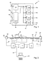
- Fig. 1 is an inventive induction module 11 is shown schematically from the structure.
- the power electronics 13 is arranged on the right side, which consists of four power electronics modules 14a - 14d. These can be the same, but they do not have to and can under certain circumstances also be designed in each case for different services and in particular be of different sizes.
- Each power electronics module 14a-14d is provided with a connection 15a-15d on the housing 12, to which basically one or more induction coils are connected can.
- the maximum power of a power electronics module 14a-14d may be 5 kW.
- a fan 16 is in the Fig. 1 generally illustrated, it may cool the power electronics 13 as well as all devices in the housing.
- a controller 17 is included, in particular with a correspondingly equipped microprocessor.
- the controller 17 has a control connection 18a for said LIN bus system, in particular as a plug connection, a control connection 18b for said CAN bus system and a service connection 19, advantageously also as a plug connection.
- the induction module 11 is controlled externally via the control connection 18a, in particular also with operating commands for the operation of the induction module 11 or the power electronics modules 14a-14d, including connected induction coils. Via the control connection 18b, the induction module 11 is connected to other induction modules.
- the induction module 11 has neither built-in or directly attached induction coils nor an operating device or operating elements. Although some controls in the form of switches or power disconnectors may be provided, but not for power adjustment of the power electronics 13 or with a similar function, ie the intended operation as a heater or cooking equipment.
- a mains connection 20 and a unit 21 of line filter, rectifier and low voltage supply for the controller 17 is provided.
- This unit provides the electrical power from the mains voltage given to the induction coils by the power electronics modules 14a-14d.
- Fig. 2 an arrangement 22 is shown in which under a cooking surface 23 a plurality of induction coils 25 are arranged, each forming a cooking point 24.
- the cooking surface 23 may for example consist of glass ceramic and may also be divided into several individual fields.
- the induction coils 25 are formed in the usual manner, advantageously as flat coils, and fixed under the cooking surface 23.
- a pot 26 is exemplified, to be inductively heated by means of the induction coil 25 at this cooking point 24 below.
- the arrangement or the cooking device 22 has two operating devices 28, one on each side, each having control elements 29, for example, so-called rotary knob or alternatively touch switch. It may also be quite more controls 28 may be provided.
- the operating devices 28 are each connected via a connection 32 to an induction module 11.
- This connection 32 may be formed as the aforementioned bus system or include such, advantageously as a LIN bus system.
- the communication of the operating devices 28 with the induction modules 11 via a bus, for example, a LIN bus system 32.
- a synchronization bus system advantageously a CAN bus system
- the induction modules 11 are connected via the terminals 15 with four induction coils 25 and the cooking surface 23, which is not shown for all induction modules 11.
- the distance between the induction modules 11 and the induction coils 25 may be relatively small, for example a few centimeters, in particular about 10 cm to 40 cm, when the induction modules 11 are arranged in particular directly below. Alternatively, the distance may be a few meters, so that the induction modules 11 are arranged for example in a separate room or room and their cooling and possible noise is unproblematic.
- Fig. 2 illustrated how a service PC is connected by means of a connecting cable 34 to a service port 19 of the left induction module 11 and thus also to its control.
- a certain reconfiguration or reprogramming of a controller 17 or of the corresponding induction module 11 can take place.
- operational data collected in the controller 17 during operation may be read out, for example, to identify and avoid possible errors that occur soon, to determine service intervals or to identify faulty parts more quickly.
- the number of induction modules 11 in the assembly 22 according to Fig. 2 is basically arbitrary, with a number of 5 to 10 induction modules, each with four connected induction coils is generally considered sufficient.
- a preferred induction module which then also controls, for example, the synchronization bus system of the CAN bus system mainly.
Abstract
Description
Die Erfindung betrifft ein Induktionsmodul für mindestens eine Induktionsspule als induktive Heizeinrichtung, eine Anordnung mehrerer solcher Induktionsmodule sowie ein Verfahren zur Einrichtung eines solchen Induktionsmoduls.The invention relates to an induction module for at least one induction coil as an inductive heating device, an arrangement of a plurality of such induction modules and a method for establishing such an induction module.
Es ist bekannt, sowohl bei Induktionskochfeldern für Privathaushalte als auch bei Induktionskocheinrichtungen für den gewerblichen Bereich wie beispielsweise in Restaurants, mehrere Induktionsspulen auf einer Kochfläche bzw. unter einer Kochfeldplatte anzuordnen. Die Induktionsspulen werden dabei von Induktionsmodulen bzw. von Leistungselektronikeinheiten mit Leistung versorgt und entsprechend angesteuert. Während bei Induktionskochfeldern für Privathaushalte eine abgeschlossene Funktionseinheit bilden, sind sie für den gewerblichen Bereich teilweise modular aufgebaut, um einen leichteren Austausch bzw. Erweiterungen oder Veränderungen zu ermöglichen. Üblicherweise sind dabei die Leistungselektroniken bzw. die Induktionsmodule für die Verwendung von speziellen bzw. unterschiedlichen Induktionsspulen, die durch Charakteristika wie Leistungsverbrauch und notwendige Ansteuerung gekennzeichnet sind, ausgelegt.It is known to place a plurality of induction coils on a cooking surface or under a cooktop plate, both in domestic induction hobs and in industrial induction cooking devices such as in restaurants. The induction coils are powered by induction modules or power electronic units with power and controlled accordingly. While home cooking hobs are a self-contained functional unit, for commercial use they are partially modular in design to allow for easier replacement or modification. Usually, this is the power electronics or the induction modules for the use of special or different induction coils, which are characterized by characteristics such as power consumption and necessary control designed.
Der Erfindung liegt die Aufgabe zugrunde, ein eingangs genanntes Induktionsmodul sowie eine Anordnung mehrerer solcher Induktionsmodule zu schaffen, mit denen Probleme des Standes der Technik vermieden werden können und vorteilhafte Weiterbildungen möglich sind sowie insbesondere ein verbessertes Zusammenwirken mehrerer solcher Induktionsmodule möglich ist.The invention has for its object to provide an induction module mentioned above and an arrangement of a plurality of such induction modules, which problems of the prior art can be avoided and advantageous developments are possible and in particular an improved interaction of several such induction modules is possible.
Gelöst wird diese Aufgabe durch ein Induktionsmodul mit den Merkmalen des Anspruchs 1 sowie eine Anordnung mehrerer solcher Induktionsmodule mit den Merkmalen des Anspruchs 8 und ein Verfahren mit den Merkmalen des Anspruchs 14. Vorteilhafte sowie bevorzugte Ausgestaltungen der Erfindung sind Gegenstand der weiteren Ansprüche und werden im Folgenden näher erläutert. Der Wortlaut der Ansprüche wird durch ausdrückliche Bezugnahme zum Inhalt der Beschreibung gemacht. Des weiteren wird der Wortlaut der Prioritätsanmeldung
Es ist vorgesehen, dass ein Induktionsmodul für mindestens eine Induktionsspule als induktive Heizeinrichtung vorgesehen ist, vorteilhaft für mehrere Induktionsspulen vorgesehen ist. Ein Induktionsmodul weist eine Leistungselektronik zur Leistungsversorgung für die eine oder die mehreren Induktionsspulen auf sowie eine Steuerung für die Ansteuerung dieser Leistungselektronik. Dabei sind die Leistungselektronik und die Steuerung in einem Gehäuse des Induktionsmoduls angeordnet bzw. sie sind in einer Funktionseinheit zusammengefasst. Erfindungsgemäß weist das Induktionsmodul bzw. die Steuerung ein Synchronisations-Bussystem auf zur Synchronisierung bzw. Verbindung dieses Induktionsmoduls mit anderen Induktionsmodulen. Der Vorteil eines solchen Synchronisations-Bussystems liegt darin, dass mehrere Induktionsmodule bzw. deren Leistungselektroniken mit den Induktionsspulen zu größeren, sozusagen virtuellen Geräten zusammengeschaltet werden können und dann unter Umständen gemeinsam bzw. nach gemeinsamen Vorgaben angesteuert werden können. Darauf wird nachfolgend noch genauer eingegangen.It is provided that an induction module is provided for at least one induction coil as an inductive heating device, is advantageously provided for a plurality of induction coils. An induction module has a power electronics for power supply for the one or more induction coils and a controller for controlling these power electronics. The power electronics and the controller are arranged in a housing of the induction module or they are combined in a functional unit. According to the invention, the induction module or the controller has a synchronization bus system for synchronizing or connecting this induction module with other induction modules. The advantage of such a synchronization bus system is that a plurality of induction modules or their power electronics can be interconnected with the induction coils to larger, so to speak virtual devices and then under certain circumstances together or can be controlled according to common specifications. This will be discussed in more detail below.
In vorteilhafter Ausbildung der Erfindung ist ein Induktionsmodul ohne Bedienelemente ausgebildet, jedenfalls für den Betrieb. Bei einer Anordnung mehrerer Induktionsmodule gemäß der Erfindung ist es möglich, dass entweder eine separate Bedieneinrichtung mit Bedienelementen vorgesehen ist, die zwar mit den Induktionsmodulen verbunden ist, aber darin nicht gerätemäßig integriert ist. Alternativ kann eine Bedieneinrichtung aber auch an einem Induktionsmodul von vielen bzw. an oder in dessen Gehäuse vorgesehen sein. Ein solches Induktionsmodul ist dann sozusagen ein übergeordnetes Induktionsmodul für die Gesamtanordnung mit den anderen Induktionsmodulen.In an advantageous embodiment of the invention, an induction module without controls is formed, at least for the operation. In an arrangement of a plurality of induction modules according to the invention, it is possible that either a separate control device is provided with controls, which is indeed connected to the induction modules, but is not integrated device in device. Alternatively, however, an operating device may also be provided on an induction module of many or on or in its housing. Such an induction module is then, so to speak, a higher-level induction module for the overall arrangement with the other induction modules.
In weiterer Ausgestaltung der Erfindung ist es vorteilhaft, wenn die Induktionsmodule ohne Induktionsspulen ausgebildet sind bzw. diese nicht aufweisen, also keine gerätemäßige Einheit mit ihnen bilden. So sind der Anschluss und die gemeinsame Verwendung mit beliebigen Induktionsspulen möglich für eine größere Flexibilität beim Einsatz.In a further embodiment of the invention, it is advantageous if the induction modules are formed without induction coils or do not have them, so do not form a device-like unit with them. Thus, the connection and the common use with any induction coils are possible for greater flexibility in use.
Vorteilhaft ist ein Induktionsmodul bzw. seine Leistungselektronik dazu ausgebildet, eine oder mehrere Induktionsspulen anzusteuern. Dabei kann von einem Induktionsmodul eine maximale Leistung, welche der Summe der Maximalleistungen der Leistungselektroniken entspricht, gesteuert werden, zum Beispiel also 5 kW pro angesteuerter Leistungselektronik, was zu einem Ausbau bei 4 Kanälen zu 20 kW führen würde welche aus dem selben Induktionsmodul gesteuert werden. Besonders vorteilhaft ist die Leistungselektronik eines Induktionsmoduls in mehrere Leistungselektronik-Module aufgeteilt, vorteilhaft ein Leistungselektronik-Modul pro anzusteuernder Induktionsspule. Aber auch mehrere Induktionsspulen pro Leistungselektronik-Modul sind denkbar in weiteren Ausbaustufen. Dies ermöglicht einen flexibleren Aufbau eines Induktionsmoduls, so dass je nach gewünschter Konfiguration von anzuschließenden Induktionsspulen entsprechende Leistungselektronik-Module in das Induktionsmodul eingesetzt werden können. So kann eine an eine entsprechende Induktionsspulenkonfiguration technisch und preismäßig optimal angepasste Konfiguration von Leistungselektronik-Modulen bzw. der gesamten Leistungselektronik im Induktionsmodul erreicht werden.Advantageously, an induction module or its power electronics is designed to control one or more induction coils. In this case, a maximum power, which corresponds to the sum of the maximum powers of the power electronics, can be controlled by an induction module, for example 5 kW per driven power electronics, which would lead to an expansion with 4 channels to 20 kW which are controlled from the same induction module. Particularly advantageously, the power electronics of an induction module is divided into a plurality of power electronics modules, advantageously a power electronics module per induction coil to be controlled. But also several induction coils per power electronics module are conceivable in further expansion stages. This allows a more flexible construction of an induction module, so that depending on the desired configuration of induction coils to be connected corresponding power electronics modules can be used in the induction module. Thus, a configuration of power electronics modules or the entire power electronics in the induction module, which is optimally matched to a corresponding induction coil configuration in terms of technology and pricing, can be achieved.
Das Synchronisations-Bussystem ist bevorzugt in der Steuerung des Induktionsmoduls integriert bzw. wird dadurch bereitgestellt. Vorteilhaft wird dafür ein sogenanntes serielles Bussystem verwendet, beispielsweise ein CAN-Bussystem, dem noch einige Signale hinzugefügt sind. Dessen Funktionalität ist für die Zwecke der vorliegenden Erfindung als optimal anzusehen. Ein solches CAN-Bussystem kann beliebig viele verschiedene Induktionsmodule funktional zusammenschalten. Darauf wird nachfolgend noch genauer eingegangen.The synchronization bus system is preferably integrated in the control of the induction module or is provided thereby. For this purpose, a so-called serial bus system is advantageously used, for example a CAN bus system to which a few signals have still been added. Its functionality is considered optimal for the purposes of the present invention. Such a CAN bus system can functionally interconnect any number of different induction modules. This will be discussed in more detail below.
In weiterer Ausgestaltung der Erfindung kann ein Induktionsmodul ein Service-Interface aufweisen für eine leichtere und bessere Zugänglichkeit. Dafür kann beispielsweise ein Service-Anschlussstecker am Induktionsmodul vorgesehen sein, über den nach Anschluss eines entsprechenden externen Service-Gerätes Daten eingegeben oder ausgelesen werden können. So ist beispielsweise eine Parametrisierung bzw. Einstellung der Steuerung oder auch der Leistungselektronik möglich. Bestimmte Betriebsparameter können so nachträglich auch verändert werden, beispielsweise als nachträgliche Anpassung an mit der Leistungselektronik verbundenen Induktionsspulen.In a further embodiment of the invention, an induction module may have a service interface for easier and better accessibility. For example, a service connection plug can be provided on the induction module, via which data can be input or read out after connection of a corresponding external service device. For example, a parameterization or adjustment of the control or the power electronics is possible. Certain operating parameters can also be subsequently changed, for example, as a subsequent adaptation to induction coils connected to the power electronics.
Vorteilhaft ist jedes Induktionsmodul als eigenes Modul bzw. in einem eigenen Gehäuse vorgesehen. So kann bei einer erfindungsgemäßen Anordnung mehrerer solcher Induktionsmodule eine Ansammlung dieser Gehäuse vorgesehen sein. Die Gehäuse weisen neben der Leistungselektronik und einer Steuerung auf einer oder mehrerer Steuerungsplatinen Steuerungseinheiten für Lüfter zur Kühlung sowie entsprechende Anschlussmöglichkeiten in Form von Stecker, Schraubklemmen odgl. auf. Besonders vorteilhaft sind die Gehäuse für sämtliche Ausbildungen von Induktionsmodulen gleich ausgebildet und werden dann entsprechend bestückt, beispielsweise auch mit unterschiedlicher Anzahl von Leistungselektroniken, abhängig von der mit einem Induktionsmodul anzusteuernden Anzahl von Induktionsspulen.Each induction module is advantageously provided as a separate module or in a separate housing. Thus, in an arrangement according to the invention of a plurality of such induction modules, an accumulation of these housings can be provided. The housing has, in addition to the power electronics and a controller on one or more control boards control units for cooling fans and corresponding connection options in the form of plugs, screw terminals or the like. on. Particularly advantageous housing for all training of induction modules are the same design and then equipped accordingly, for example, with different numbers of power electronics, depending on the number of induction coils to be controlled with an induction module.
Bei der erfindungsgemäßen Anordnung von einem oder vorteilhaft mehreren Induktionsmodulen weisen diese jeweils mehrere Induktionsspulen auf bzw. sind mit diesen verbunden. Die Induktionsmodule sind miteinander über ein Synchronisations-Bussystem verbunden, welches besonders vorteilhaft ein serielles Bussystem ist. Des weiteren gehört zu der Anordnung mindestens eine Bedieneinrichtung mit entsprechenden Bedienelementen, um die Induktionsmodule damit zu steuern bzw. letztendlich den Betrieb der angesteuerten Induktionsspule. Vorteilhaft ist dabei die Bedieneinrichtung entfernt von den Induktionsmodulen vorgesehen und über eine Datenverbindung mit einem Induktionsmodul verbunden, welche drahtlos oder aber auch über Kabel erfolgen kann. Die Verbindung ist auch hier vorteilhaft ein Bussystem, besonders vorteilhaft ein LIN-Bussystem, also ein Bussystem mit einem Local Interconnect Network. Über Bedienelemente an der mindestens einen Bedieneinrichtung kann die Steuerung jedes Induktionsmoduls entsprechend angesprochen und so der Betrieb der damit verbundenen Induktionsspulen gesteuert werden, wobei es möglich ist, dass eine Bedieneinrichtung an ein Induktionsmodul verbunden ist und über dieses bzw. das Synchronisations-Bussystem alle Induktionsmodule mit dieser einen Bedieneinrichtung gesteuert werden.In the inventive arrangement of one or more advantageous induction modules, these each have a plurality of induction coils or are connected thereto. The induction modules are connected to each other via a synchronization bus system, which is particularly advantageously a serial bus system. Furthermore, at least one operating device with corresponding operating elements is part of the arrangement in order to control the induction modules therewith or, ultimately, the operation of the controlled induction coil. Advantageously, the operating device is provided away from the induction modules and connected via a data connection with an induction module, which can be done wirelessly or via cable. The connection is also advantageous here a bus system, particularly advantageous a LIN bus system, ie a bus system with a Local Interconnect Network. About controls on the at least one operating device, the control of each induction module can be addressed accordingly and so the operation of the associated induction coils are controlled, it being possible that an operating device is connected to an induction module and via this or the synchronization bus system All induction modules are controlled with this one operating device.
Es können auch mehrere Bedieneinrichtungen für mehrere Induktionsmodule vorgesehen sein, und zwar an verschiedenen Stellen. So ist gerade bei einem Aufbau mit einer größeren Anzahl von Induktionsspulen, also beispielsweise einer großen Heizfläche mit beispielsweise 10 bis 20 Heizstellen, eine Bedienung bzw. Einstellung von mehreren Positionen aus möglich. Dies verbessert die Handhabbarkeit und Praxistauglichkeit einer solchen Anordnung bzw. einer davon gebildeten Heizfläche. Besonders vorteilhaft sind die Bedieneinrichtungen dabei aber in direkter Nähe zu der Heizfläche vorgesehen. Die Induktionsmodule können in Ausgestaltung der Erfindung durchaus weiter entfernt von der Heizfläche bzw. den Induktionsspulen vorgesehen sein. Sie können beispielsweise in einem separaten Raum im selben Gebäude angeordnet sein, um Geräuschproblematik, Wärmeentwicklung und Kühlung zu vereinfachen. Besonders vorteilhaft kann eine solche Anordnung eine Kocheinrichtung sein, also eine Art großes Kochfeld, wobei jede Induktionsspule eine Kochstelle für einen Topf definieren kann. Auch andere Heizeinrichtungen für induktive Beheizung sind möglich, beispielsweise bei Schmelzöfen odgl..It is also possible to provide a plurality of operating devices for a plurality of induction modules, specifically at different locations. Thus, just in a structure with a larger number of induction coils, so for example a large heating surface with, for example, 10 to 20 hot spots, an operation or setting of several positions from possible. This improves the manageability and practicality of such an arrangement or a heating surface formed thereof. However, the operating devices are particularly advantageously provided in the immediate vicinity of the heating surface. In an embodiment of the invention, the induction modules can certainly be provided further away from the heating surface or the induction coils. For example, they can be located in a separate room in the same building to simplify noise, heat and cooling. Particularly advantageous, such an arrangement may be a cooking device, so a kind of large hob, each induction coil can define a cooking point for a pot. Other heaters for inductive heating are possible, for example, in furnaces smelting ..
Eine vorbeschriebene Anordnung oder auch nur ein Induktionsmodul kann zwar lauter identische Induktionsspulen aufweisen. Vorteilhaft sind die Induktionsspulen aber zumindest teilweise unterschiedlich ausgebildet hinsichtlich der Parameter wie Größe, Leistung oder Bauform, so dass eine vielfältigere Verwendbarkeit gegeben ist bzw. dass für unterschiedlich große Heizflächen, beispielsweise unterschiedlich große Töpfe, sowie unterschiedliche Leistungsstufen jeweils eine geeignete Induktionsspule als Heizquelle vorhanden ist. Bei der Anordnung als Heizfläche bzw. Heizeinrichtung können die Induktionsspulen in Ausgestaltung der Erfindung einen geringen Abstand zueinander aufweisen, beispielsweise maximal wenige Millimeter, insbesondere weniger als vier Zentimeter. So ist es beispielsweise auch vorstellbar, dass zwei Induktionsspulen gemeinsam von einem einzigen Topf überdeckt werden und diesen beheizen. Ob derart nahe beieinander angeordnete Induktionsspulen von demselben Induktionsmodul angesteuert werden oder von verschiedenen, spielt dabei keine Rolle. Einer der Hauptvorteile der Verbindung mehrerer Induktionsmodule miteinander durch das genannte Synchronisations-Bussystem liegt nämlich darin, dass sie einen beliebig gemeinsamen aufeinander abgestimmten und problemlosen Betrieb mehrerer Induktionsmodule und Leistungselektroniken mit deren lnduktionsspulen ermöglichen.Although a prescribed arrangement or even an induction module may have louder identical induction coils. Advantageously, however, the induction coils are at least partially formed differently in terms of parameters such as size, power or design, so that a more versatile usability is given or that for different sized heating surfaces, for example, different sized pots, and different power levels each have a suitable induction coil is available as a heating source , In the arrangement as a heating surface or heating device, the induction coils in an embodiment of the invention may have a small distance from one another, for example a maximum of a few millimeters, in particular less than four centimeters. For example, it is also conceivable that two induction coils are covered together by a single pot and heat it. Whether arranged close to each other induction coils are driven by the same induction module or by different, does not matter. One of the main advantages of connecting a plurality of induction modules to each other by means of said synchronization bus system lies in the fact that they permit any common coordinated and problem-free operation of a plurality of induction modules and power electronics with their induction coils.
Bei einem erfindungsgemäßen Verfahren zur Einrichtung eines genannten Induktionsmoduls oder einer genannten Anordnung mehrerer Induktionsmodule kann über das Synchronisations-Bussystem bzw. das Service-Interface das Zusammenarbeiten einzelner Bedienelemente, Induktionsmodule und/oder deren Leistungselektronik definiert werden. Des weiteren können darüber erfindungsgemäß aktuelle sowie zurückliegende Betriebsdaten oder Betriebsparameter ausgelesen werden. Vorteilhaft kann ein so genanntes Energiemanagement eingespeichert werden welches durch eine Schnittstelle parametrisierbar ist, so dass einzelne Induktionsmodule oder auch deren Anordnung nicht mehr als eine bestimmte Gesamtspitzenleistung aus dem Versorgungsnetz beziehen. So kann auf tarifliche Vorgaben oder Unterschiede von Stromanbietern reagiert werden bzw. Spitzenverbräuche können reduziert oder ganz vermieden werden. Auch Netzrückwirkungen oder ungewünscht hohe Blindleistungen können so reduziert oder vermieden werden, beispielsweise durch Leistungsverschiebungen beim Betrieb einer größeren Anzahl von Induktionsspulen. Bislang notwendige Energieoptimierungsanlagen von separaten Herstellern, die aufwendig an bisheriger induktive Kocheinrichtungen angeschlossen werden mussten, können so vermieden und der Prozess der Energieverteilung optimiert werden.In a method according to the invention for setting up an aforementioned induction module or a named arrangement of a plurality of induction modules, the cooperation of individual operating elements, induction modules and / or their power electronics can be defined via the synchronization bus system or the service interface. Furthermore, current and past operating data or operating parameters can be read out according to the invention. Advantageously, a so-called energy management can be stored which can be parameterized by an interface, so that individual induction modules or their arrangement do not relate more than a specific total peak power from the supply network. In this way, it is possible to react to tariff specifications or differences between electricity providers, or peak consumption can be reduced or completely avoided. Even network perturbations or undesirably high reactive power can be reduced or avoided, for example, by power shifts in the operation of a larger number of induction coils. So far necessary energy optimization plants of separate manufacturers, which had to be connected consuming at past inductive cooking devices, can thus be avoided and the process of energy distribution can be optimized.
Diese und weitere Merkmale gehen außer aus den Ansprüchen auch aus der Beschreibung und den Zeichnungen hervor, wobei die einzelnen Merkmale jeweils für sich allein oder zu mehreren in Form von Unterkombination bei einer Ausführungsform der Erfindung und auf anderen Gebieten verwirklicht sein und vorteilhafte sowie für sich schutzfähige Ausführungen darstellen können, für die hier Schutz beansprucht wird. Die Unterteilung der Anmeldung in einzelne Abschnitte sowie Zwischen-Überschriften beschränken die unter diesen gemachten Aussagen nicht in ihrer Allgemeingültigkeit.These and other features will become apparent from the claims but also from the description and drawings, wherein the individual features each alone or more in the form of sub-combination in one embodiment of the invention and in other areas be realized and advantageous and protectable Represent embodiments for which protection is claimed here. The subdivision of the application into individual sections as well as intermediate headings does not restrict the general validity of the statements made thereunder.
Ausführungsbeispiele der Erfindung sind in den Zeichnungen schematisch dargestellt und werden im Folgenden näher erläutert. In den Zeichnungen zeigen:
- Fig. 1
- eine schematische Darstellung des Aufbaus eines Induktionsmoduls mit Leistungselektronik und Steuerung sowie Anschlüssen und
- Fig. 2
- eine Anordnung mehrerer Induktionsmodule aus
Fig. 1 als Kocheinrichtung mit einer gemeinsamen Kochfläche.
- Fig. 1
- a schematic representation of the structure of an induction module with power electronics and control and connections and
- Fig. 2
- an arrangement of multiple induction modules
Fig. 1 as a cooking device with a common cooking surface.
In
In dem Gehäuse 12 des Induktionsmoduls 11 ist auch eine Steuerung 17 enthalten, insbesondere mit einem entsprechend ausgestatteten Mikroprozessor. Die Steuerung 17 weist einen Steuerungsanschluss 18a für das genannte LIN-Bussystem auf, insbesondere als Steckanschluss, einen Steuerungsanschluss 18b für das genannte CAN-Bussystem sowie einen Service-Anschluss 19, vorteilhaft ebenfalls als Steckanschluss. Über den Steuerungsanschluss 18a wird das Induktionsmodul 11 von außen angesteuert, insbesondere auch mit Bedienbefehlen für den Betrieb des Induktionsmoduls 11 bzw. der Leistungselektronik-Module 14a - 14d samt angeschlossener Induktionsspulen. Über den Steuerungsanschluss 18b ist das Induktionsmodul 11 mit anderen Induktionsmodulen verbunden.In the
Wie zu erkennen ist, weist das Induktionsmodul 11 weder eingebaute bzw. daran direkt befestigte Induktionsspulen auf noch eine Bedieneinrichtung oder Bedienelemente. Zwar können manche Bedienelemente in Form von Schaltern bzw. Netztrennungsschaltern vorgesehen sein, jedoch keine zur Leistungseinstellung der Leistungselektronik 13 oder mit einer vergleichbaren Funktion, also zum bestimmungsgemäßen Betrieb als Heizeinrichtung bzw. als Kocheinrichtung.As can be seen, the
Ebenso ist ein Netzanschluss 20 sowie eine Einheit 21 aus Netzfilter, Gleichrichter und Kleinspannungs-Versorgung für die Steuerung 17 vorgesehen. Diese Einheit stellt die elektrische Leistung zur Verfügung aus der Netzspannung, die von den Leistungselektronik-Modulen 14a - 14d umgewandelt an die Induktionsspulen gegeben wird.Likewise, a
In
Die Anordnung bzw. die Kocheinrichtung 22 weist zwei Bedieneinrichtungen 28 auf, eine an jeder Seite, die jeweils Bedienelemente 29 aufweisen, beispielsweise sogenannte Drehknebel oder alternativ Berührschalter. Es können auch durchaus mehr Bedieneinrichtungen 28 vorgesehen sein.The arrangement or the
Die Bedieneinrichtungen 28 sind jeweils über eine Verbindung 32 mit einem Induktionsmodul 11 verbunden. Diese Verbindung 32 kann als vorgenanntes Bussystem ausgebildet sein bzw. ein solches beinhalten, vorteilhaft als LIN-Bussystem. Somit erfolgt dadurch die Kommunikation der Bedieneinrichtungen 28 mit den Induktionsmodulen 11 über einen Bus, beispielsweise ein LIN-Bussystem 32. Die Kommunikation der Induktionsmodule 11 miteinander erfolgt über ein Synchronisations-Bussystem, vorteilhaft ein CAN-Bussystem, als Verbindung 31. Ebenso kann damit die vorgenannte Einrichtung oder Programmierung der Induktionsmodule erfolgen. Dies sind eingangs genannte wichtige Vorteile der Erfindung.The operating
Die Induktionsmodule 11 sind über die Anschlüsse 15 mit je vier Induktionsspulen 25 und der Kochfläche 23 verbunden, was jedoch nicht für alle Induktionsmodule 11 dargestellt ist. Die Entfernung zwischen den Induktionsmodulen 11 und den Induktionsspulen 25 kann relativ gering sein, beispielsweise einige Zentimeter, insbesondere etwa 10 cm bis 40 cm, wenn die Induktionsmodule 11 insbesondere direkt darunter angeordnet sind. Alternativ kann die Entfernung auch einige Meter betragen, so dass die Induktionsmodule 11 beispielsweise in einem separaten Raum bzw. Zimmer angeordnet sind und deren Kühlung sowie auch mögliche Geräuschentwicklung unproblematisch ist.The
Des Weiteren ist in
Die Anzahl der Induktionsmodule 11 in der Anordnung 22 gemäß
Des Weiteren ist es möglich, innerhalb der Anordnung 22 bzw. innerhalb der Induktionsmodule 11 ein bevorzugtes Induktionsmodul festzulegen, welches dann beispielsweise auch das Synchronisations-Bussystem des CAN-Bussystems hauptsächlich steuert.Furthermore, it is possible to define within the
Claims (15)
Applications Claiming Priority (1)
| Application Number | Priority Date | Filing Date | Title |
|---|---|---|---|
| DE102007050341A DE102007050341A1 (en) | 2007-10-12 | 2007-10-12 | Induction module, arrangement of several induction modules and method for setting up such an induction module |
Publications (2)
| Publication Number | Publication Date |
|---|---|
| EP2048913A2 true EP2048913A2 (en) | 2009-04-15 |
| EP2048913A3 EP2048913A3 (en) | 2011-06-29 |
Family
ID=40087763
Family Applications (1)
| Application Number | Title | Priority Date | Filing Date |
|---|---|---|---|
| EP08017548A Withdrawn EP2048913A3 (en) | 2007-10-12 | 2008-10-07 | Induction module, assembly of several induction modules and method for assembling such an induction module |
Country Status (6)
| Country | Link |
|---|---|
| US (1) | US20090101638A1 (en) |
| EP (1) | EP2048913A3 (en) |
| JP (1) | JP2009099566A (en) |
| CN (1) | CN101426310A (en) |
| CA (1) | CA2640816A1 (en) |
| DE (1) | DE102007050341A1 (en) |
Families Citing this family (4)
| Publication number | Priority date | Publication date | Assignee | Title |
|---|---|---|---|---|
| EP2779788B1 (en) * | 2013-03-11 | 2015-08-19 | Electrolux Appliances Aktiebolag | A method for assigning induction coils of an induction cooking hob and an induction cooking hob |
| US20140260775A1 (en) * | 2013-03-15 | 2014-09-18 | Bsh Home Appliances Corporation | Encoder selector for a module of a household cooking appliance |
| DE102013213464A1 (en) * | 2013-07-09 | 2014-08-07 | E.G.O. Elektro-Gerätebau GmbH | Induction heating device for use in induction hob, has heat pipe that is arranged between heat sources and heat sink, for radiating heat from heat sink to heat sources |
| EP3209093B1 (en) * | 2016-02-19 | 2018-09-12 | Electrolux Appliances Aktiebolag | Induction module and induction hob |
Citations (1)
| Publication number | Priority date | Publication date | Assignee | Title |
|---|---|---|---|---|
| WO2006032292A1 (en) * | 2004-09-23 | 2006-03-30 | E.G.O. Elektro-Gerätebau GmbH | Heating device for a planar heater with induction heating elements |
Family Cites Families (11)
| Publication number | Priority date | Publication date | Assignee | Title |
|---|---|---|---|---|
| US215605A (en) * | 1879-05-20 | Improvement in | ||
| DE19529434B4 (en) * | 1995-08-10 | 2009-09-17 | Continental Teves Ag & Co. Ohg | Microprocessor system for safety-critical regulations |
| CH690891A5 (en) * | 1996-03-07 | 2001-02-15 | Thomann Electronics Ag | Heater control for induction hob. |
| US5786996A (en) * | 1996-06-28 | 1998-07-28 | Eaton Corporation | Appliance control circuit comprising dual microprocessors for enhanced control operation and agency safety redundancy and software application method thereof |
| EP1280381A3 (en) * | 2001-07-25 | 2005-12-21 | I. A. S. Induktions- Anlagen + Service GmbH & Co. KG | Inductive heating device and process of billets with a billets heating coil |
| WO2003035952A1 (en) * | 2001-09-28 | 2003-05-01 | E.I. Du Pont De Nemours And Company | Hetero-composite yarn, fabrics thereof and methods of making |
| DE10161743B4 (en) * | 2001-12-15 | 2004-08-05 | Hüttinger Elektronik GmbH & Co. KG | High-frequency excitation system |
| CH696649A5 (en) * | 2003-06-30 | 2007-08-31 | Elatronic Ag | Method and apparatus for power control of induction cookers. |
| FR2863039B1 (en) * | 2003-11-27 | 2006-02-17 | Brandt Ind | METHOD FOR HEATING A CONTAINER POSITIONED ON A COOKTOP HAVING HEATING MEANS ASSOCIATED WITH INDUCERS |
| US7069109B2 (en) * | 2004-11-09 | 2006-06-27 | E.G.O. North America, Inc. | Systems and methods of using multiple microcontrollers for fail-safe control and enhanced feature operation of an appliance |
| US7687748B2 (en) * | 2005-08-01 | 2010-03-30 | Western Industries, Inc. | Induction cook top system with integrated ventilator |
-
2007
- 2007-10-12 DE DE102007050341A patent/DE102007050341A1/en not_active Ceased
-
2008
- 2008-10-07 EP EP08017548A patent/EP2048913A3/en not_active Withdrawn
- 2008-10-08 JP JP2008261645A patent/JP2009099566A/en active Pending
- 2008-10-08 CA CA002640816A patent/CA2640816A1/en not_active Abandoned
- 2008-10-09 US US12/248,322 patent/US20090101638A1/en not_active Abandoned
- 2008-10-10 CN CNA2008101769896A patent/CN101426310A/en active Pending
Patent Citations (1)
| Publication number | Priority date | Publication date | Assignee | Title |
|---|---|---|---|---|
| WO2006032292A1 (en) * | 2004-09-23 | 2006-03-30 | E.G.O. Elektro-Gerätebau GmbH | Heating device for a planar heater with induction heating elements |
Also Published As
| Publication number | Publication date |
|---|---|
| EP2048913A3 (en) | 2011-06-29 |
| US20090101638A1 (en) | 2009-04-23 |
| CA2640816A1 (en) | 2009-04-12 |
| JP2009099566A (en) | 2009-05-07 |
| CN101426310A (en) | 2009-05-06 |
| DE102007050341A1 (en) | 2009-04-23 |
Similar Documents
| Publication | Publication Date | Title |
|---|---|---|
| EP2100478B1 (en) | Method for controlling induction heating devices in an electric cooking appliance | |
| EP3353471B1 (en) | Cooking appliance in the form of a combined steamer comprising two cooking appliance units | |
| EP2095686B1 (en) | Heating device circuit | |
| DE102013216290B4 (en) | Heating device and method for operating a heating device | |
| EP2206407A1 (en) | Cooking device | |
| WO2008058614A1 (en) | Inductive cooking zone, induction hob and drive method | |
| DE102012210844A1 (en) | Cook arrangement, has power/rotation speed conversion module built in cooking field or in exhaust hood for converting different heating powers of cooking field into different rotation speeds of ventilator motor of exhaust hood | |
| WO2006032292A1 (en) | Heating device for a planar heater with induction heating elements | |
| EP2048913A2 (en) | Induction module, assembly of several induction modules and method for assembling such an induction module | |
| EP2868979B1 (en) | Cooking device and method for controlling a cooking device | |
| EP2898596B1 (en) | Thermodynamic cyclical process assembly | |
| EP2680246B1 (en) | Domestic appliance | |
| DE10327273B4 (en) | Stove with a hob and with a module to control the hob | |
| DE102012210852A1 (en) | Hob for cooking apparatus e.g. oven, has hob main portion that is connected with oven portion through electrical supply conduit supplied with electric power by another electrical supply conduit | |
| DE102013207786A1 (en) | Induction heating device e.g. induction hob device for domestic appliance, has three heating frequency units which are simultaneously connected with different power supplies through switch unit | |
| DE19900185A1 (en) | Method and device for switching consumers of an electrical device | |
| EP4209117A1 (en) | Cooktop device and method for operating a cooktop device | |
| DE19713315C2 (en) | Circuit for assigning power control signals to hotplates | |
| DE102006038412A1 (en) | Cooking appliance comprises power electronics arrangement arranged in area of cooking hob detached from control element arrangement, where power electronics arrangement is arranged in rear edge area of cooking hob | |
| DE102004036899A1 (en) | System with a cooking device and several control devices and control device | |
| DE102020202990A1 (en) | Control panel for different types of household appliances | |
| DE102012211399A1 (en) | Home appliance device e.g. cooking hob device has control unit that controls heating units to increase heating power of one heating zone more than other heating zone during specific mode of operation | |
| CH698933B1 (en) | Ceramic hob for inductively heatable hob apparatus i.e. wok pan, has control- and power electric for controlling cooking zones and providing power to zones, and attached on side of hob, where side lies opposite to utilization surface | |
| EP3709121B1 (en) | Control terminal for controlling heating or cooling devices in buildings | |
| EP2590475B1 (en) | Induction heating device |
Legal Events
| Date | Code | Title | Description |
|---|---|---|---|
| PUAI | Public reference made under article 153(3) epc to a published international application that has entered the european phase |
Free format text: ORIGINAL CODE: 0009012 |
|
| AK | Designated contracting states |
Kind code of ref document: A2 Designated state(s): AT BE BG CH CY CZ DE DK EE ES FI FR GB GR HR HU IE IS IT LI LT LU LV MC MT NL NO PL PT RO SE SI SK TR |
|
| AX | Request for extension of the european patent |
Extension state: AL BA MK RS |
|
| PUAL | Search report despatched |
Free format text: ORIGINAL CODE: 0009013 |
|
| AK | Designated contracting states |
Kind code of ref document: A3 Designated state(s): AT BE BG CH CY CZ DE DK EE ES FI FR GB GR HR HU IE IS IT LI LT LU LV MC MT NL NO PL PT RO SE SI SK TR |
|
| AX | Request for extension of the european patent |
Extension state: AL BA MK RS |
|
| AKY | No designation fees paid | ||
| REG | Reference to a national code |
Ref country code: DE Ref legal event code: R108 Effective date: 20120307 |
|
| STAA | Information on the status of an ep patent application or granted ep patent |
Free format text: STATUS: THE APPLICATION IS DEEMED TO BE WITHDRAWN |
|
| 18D | Application deemed to be withdrawn |
Effective date: 20111230 |