EP2048758A2 - Stromversorgungsvorrichtung, Stromverwaltungsserver, Stromverwaltungssystem, Stromversorgungsverfahren - Google Patents
Stromversorgungsvorrichtung, Stromverwaltungsserver, Stromverwaltungssystem, Stromversorgungsverfahren Download PDFInfo
- Publication number
- EP2048758A2 EP2048758A2 EP08002880A EP08002880A EP2048758A2 EP 2048758 A2 EP2048758 A2 EP 2048758A2 EP 08002880 A EP08002880 A EP 08002880A EP 08002880 A EP08002880 A EP 08002880A EP 2048758 A2 EP2048758 A2 EP 2048758A2
- Authority
- EP
- European Patent Office
- Prior art keywords
- power
- data
- power supply
- section
- control
- Prior art date
- Legal status (The legal status is an assumption and is not a legal conclusion. Google has not performed a legal analysis and makes no representation as to the accuracy of the status listed.)
- Withdrawn
Links
Images


Classifications
-
- H—ELECTRICITY
- H02—GENERATION; CONVERSION OR DISTRIBUTION OF ELECTRIC POWER
- H02J—ELECTRIC POWER NETWORKS; CIRCUIT ARRANGEMENTS OR SYSTEMS FOR SUPPLYING OR DISTRIBUTING ELECTRIC POWER; SYSTEMS FOR STORING ELECTRIC ENERGY
- H02J1/00—Circuit arrangements for DC mains or DC distribution networks
- H02J1/14—Balancing load and power generation in DC networks
-
- G—PHYSICS
- G06—COMPUTING OR CALCULATING; COUNTING
- G06F—ELECTRIC DIGITAL DATA PROCESSING
- G06F1/00—Details not covered by groups G06F3/00 - G06F13/00 and G06F21/00
- G06F1/26—Power supply means, e.g. regulation thereof
- G06F1/266—Arrangements to supply power to external peripherals either directly from the computer or under computer control, e.g. supply of power through the communication port, computer controlled power-strips
-
- H—ELECTRICITY
- H01—ELECTRIC ELEMENTS
- H01R—ELECTRICALLY-CONDUCTIVE CONNECTIONS; STRUCTURAL ASSOCIATIONS OF A PLURALITY OF MUTUALLY-INSULATED ELECTRICAL CONNECTING ELEMENTS; COUPLING DEVICES; CURRENT COLLECTORS
- H01R13/00—Details of coupling devices of the kinds covered by groups H01R12/70 or H01R24/00 - H01R33/00
- H01R13/66—Structural association with built-in electrical component
- H01R13/70—Structural association with built-in electrical component with built-in switch
-
- H—ELECTRICITY
- H01—ELECTRIC ELEMENTS
- H01R—ELECTRICALLY-CONDUCTIVE CONNECTIONS; STRUCTURAL ASSOCIATIONS OF A PLURALITY OF MUTUALLY-INSULATED ELECTRICAL CONNECTING ELEMENTS; COUPLING DEVICES; CURRENT COLLECTORS
- H01R25/00—Coupling parts adapted for simultaneous co-operation with two or more identical counterparts, e.g. for distributing energy to two or more circuits
- H01R25/003—Coupling parts adapted for simultaneous co-operation with two or more identical counterparts, e.g. for distributing energy to two or more circuits the coupling part being secured only to wires or cables
-
- H—ELECTRICITY
- H01—ELECTRIC ELEMENTS
- H01R—ELECTRICALLY-CONDUCTIVE CONNECTIONS; STRUCTURAL ASSOCIATIONS OF A PLURALITY OF MUTUALLY-INSULATED ELECTRICAL CONNECTING ELEMENTS; COUPLING DEVICES; CURRENT COLLECTORS
- H01R13/00—Details of coupling devices of the kinds covered by groups H01R12/70 or H01R24/00 - H01R33/00
- H01R13/66—Structural association with built-in electrical component
- H01R13/665—Structural association with built-in electrical component with built-in electronic circuit
- H01R13/6683—Structural association with built-in electrical component with built-in electronic circuit with built-in sensor
-
- H—ELECTRICITY
- H02—GENERATION; CONVERSION OR DISTRIBUTION OF ELECTRIC POWER
- H02J—ELECTRIC POWER NETWORKS; CIRCUIT ARRANGEMENTS OR SYSTEMS FOR SUPPLYING OR DISTRIBUTING ELECTRIC POWER; SYSTEMS FOR STORING ELECTRIC ENERGY
- H02J2105/00—Networks for supplying or distributing electric power characterised by their spatial reach or by the load
- H02J2105/50—Networks for supplying or distributing electric power characterised by their spatial reach or by the load for selectively controlling the operation of the loads
- H02J2105/54—Networks for supplying or distributing electric power characterised by their spatial reach or by the load for selectively controlling the operation of the loads according to a non-electrical condition, e.g. temperature
- H02J2105/55—Networks for supplying or distributing electric power characterised by their spatial reach or by the load for selectively controlling the operation of the loads according to a non-electrical condition, e.g. temperature according to an economic condition, e.g. tariff-based load management
Definitions
- the invention relates to a power supply apparatus, a power management server, a power management system nd a power management method according to the preambles of the independent claims.
- periphery may be plugged for power supply into a socket at the PC rather than into an own socket. Then, with switching off the PC, power supply for the peripheral components is also switched off.
- extension sockets are known having plural sockets therein, one of them being a master socket. When switching off of the appliance plugged into the master socket is detected, the other sockets are disconnected from the supply side so that the devices plugged into them do no longer receive power.
- many devices are provided with built-in standby detection. Once standby is detected, under certain further criteria, the operation mode of the device can be changed. For example, screens of PCs or workstations may, by themselves, go to off when, as a standby criterion, no changed input for a certain while has been detected.
- a power supply apparatus comprises a power receiving section allowing the connection to an electrical power source of two or three or more phases, one or more power tapping sections allowing the connection of one or more power drains or power consuming devices for receiving power, tap switching means for connecting or disconnecting the power tapping section from the power receiving section in accordance with a control signal, and control means for controlling operation of the tap switching means.
- the power supply apparatus may be a portable power strip with several sockets and a plug-provided cord for plugging it into a wall outlet. But the power supply apparatus may likewise be one or a row of power sockets built into a room wall. And likewise, the power supply apparatus may also be a central power distribution installation, for example in the basement in association with the fuse box of a private home.
- the control means is adapted to monitor one or more criteria and to control switching of the tap switching means in accordance with said monitored criteria.
- the monitoring means may monitor power consumption at one or two or more individual taps and may command switching-off (i. e. disconnection of the taps/sockets from the apparatus-internal supply line) of one or two or more taps in accordance with said monitorings.
- the power supply apparatus may have a local operation mode in which itself makes monitorings, and controls power supply in accordance with monitoring results, and possibly in accordance with other data. It may also or instead have a remote control mode in which it receives commands from remote and may also send information towards remote, communication being made through an appropriate interface of the power supply apparatus. In such a remote mode, the apparatus may communicate with a correspondingly adapted power management server which can receive data from the power supply apparatus and can generate and send control and other data to the power supply apparatus.
- the power management server may be provided remote from the power supply apparatus and connected thereto through a data net such as the internet.
- the server may also be provided closer to the power supply apparatus, for example in the same building or area or building level or block.
- Connectivity may then be rendered by a local net such as LAN, wLAN or the like, or through dedicated lines or through the power net itself carrying appropriately modulation signals on the power AC.
- a power management system consists of the above described power supply apparatus in remote mode and the described power management server, the two components being in communication with each other.
- a power supply apparatus may monitor power supply to one or more power taps thereof and may, in accordance thereto, command connecting or disconnecting power taps from the power supply in accordance with the made determinations.
- the power management method includes on the one hand side making certain monitorings and transmitting the obtained data, possibly after some sort of evaluation or compilation, towards remote.
- control data may be received from remote and switchings of power tappings may be made in accordance with the control data received from remote.
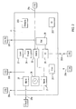
- Fig. 1 shows schematically a power supply apparatus 10. It is connectable on its power receiving side to a power source 1, for example through a plug 2 and a cord 3. On the supply side, it is connectable to power drains or power consuming devices 9, for example consumer products such as TV, a recorder, HiFi, computers, or other electric or electronic devices, consumer products, household products and machines or a power forwarding or distribution installation or another power supply apparatus.
- the apparatus 10 may supply power through tapping sections 8, 8a, ... 8n, which may be sockets for corresponding plugs.
- the apparatus may be a portable device with a housing 4. It may be a power strip with a cord 3 and a plug 2 for connection to a wall socket, and with plural own sockets 8a, ... 8n.
- the apparatus may be built-in for example as a row of sockets into the wall of a room, or it may be a power distribution installation at a central power inlet of a building or a floor of a building, or the like.
- 5, 5a, ... 5n denote internal power lines with a central line 5 and branches 5a, ... 5n corresponding to taps 8a, ... 8n.
- 15 are tap switching means which may each disconnect or reconnect one or more taps 8 from or to the power supply side. They may sit in the lines 5a, ... 5n.
- Fig. 1 shows an embodiment where each tap 8 has its own switch 15 (pairs 8a-15a, 8n-15n). But likewise, plural taps may be switched by one switching means 15. Seen in a direction towards taps 8, the switching means 15 may sit behind the power supply 17 of control means 11. Accordingly, when the switching means 15 are off (i.e., disconnection), the power supply 17 still receives power through the power receiving section and can thus supply electrical power to the control means 11.
- the control means 11 may receive various inputs. It may receive measures indicating power supplied to one or more taps or received through the receiving section. To this end, for example current sensors 19, 19a, ... 19n may be provided. They may operate inductively, or they may comprise shunts connected into the respective supply line to be detected. Each tap 8a, ... 8n may have its own power sensor 19a, ... 19n. 19z denotes a power sensor at the power input side.
- the controller may comprise signal shaping means for appropriately shaping the acquired signal, and probably also converting them into digital data. From the power sensors 19, the controller 11 gains information on power supplied to the apparatus (sensor 19z on the input side), and on power supplied to the respective taps or groups of taps (sensors 19a, ... 19n on the respective taps). Thus, possibly together with one or more suitable thresholds, the controller 11 may distinguish between standby mode (current to device 9 smaller than a first threshold larger than the first threshold) and usual operation (current larger than the second threshold). It may also distinguish between standby and off off-state of a device 9 connected to a tap 8 (current to/from the tap smaller than a second threshold smaller than the first threshold or practically 0). The thresholds may be predefined or may be externally updated from time to time, or may be learned values. Thus, the controller 11 may monitor particularly the power supply status at the various taps individually.
- One or plural or all of the taps 8 may be disconnected from power supply (by one or plural or all switches 15 being opened), when standby or 0 current is detected at one or plural or all taps. Particularly, a predetermined plurality of taps 8 (two or more of them) may be switched off when at said plurality of taps standby and/or 0 current is detected. This avoids the unwanted switching off of a certain device due to circumstances at another device.
- Switching off may be delayed for a certain period, such as 1 second or more or 10 seconds or more, after finding the related criterion met. During this time lag, the criterion may further be checked, and if found no longer met, switching off is prevented. This avoids tap switch-off and the necessity to a subsequent switch-on due to accidental device standby.
- Tap switch-off may further be prevented if some or all connected devices are themselves properly switched off, i. e. consume 0 or less than standby power. Then, switching off their taps/sockets saves nothing, and preventing some kind of tap switch-off avoids the necessity for switching the sockets on again, so that through proper device switch-off comfort is gained.
- the individual taps may be monitored (for power consumption lower than a threshold below assumed standby consumption), or at the input side of the apparatus 10 the total consumption may be monitored (sensor 19z) and compared with a suitable threshold (such as smallest of all corresponding tap thresholds, own threshold of "acceptable" consumption).
- control means 11 may generate an alarm (optical by display 13a and/or acoustical by speaker 13b) when a certain plug is removed from or inserted into a socket, for example a removed deep freeze plug or a removed plug of a programmed recorder waiting for something to be recorded. Alarm generation may be programmable for the individual taps 8.
- This alarm-upon-sensed-plug-operation may constitute an own inventive aspect independent of, but preferably combinable with, one or more of the further features described in this specification.
- Switching means 14 may be provided on the input side and particularly between power source 1 and power supply 17a of control means 11. Thus, also the control means 11 can be disconnected from power supply to that the power supply apparatus 10 itself does not consume power.
- a (chargeable) battery 17b or other electrical power storage means may be provided which supplies (possibly intermittently) power to control means 11, so that it can maintain certain functionalities even when switch 14 is in off-state.
- the apparatus 10 may be provided with activating means 16 for reestablishing connections of the taps 8 and possibly of the power supply side.
- the activating means 16 may cause switches 14 and 15 to close, i.e. to establish power supply.
- the activating means 16 may be a separate box connected to the main body 4 of the apparatus 10 through a wire.
- the activation means 16 may be located such that it is conveniently reachable for a user or technically reachable for input, such a infrared input.
- the activation means 16 may comprise a button or switch 16a, or the like to be operated by a user manually.
- the activation means 16 may comprise a signal receiver 16b for receiving signals for example from remote controls of TV, DVD, etc.
- Receiver 16b may be constructed such that it is responsive to all usual remote control signals (radio signals in a certain frequency range, infrared signals, ultrasonic, ). With such an activation means 16 it is possible that a user commands reestablishing power supply by closing the switches 14 and 15. More in detail, control means 11 receives certain signals from activation means 16 and generates in response thereto control signals to the respective switches 14, 15.
- the display 13a symbolizes display means which may be or comprise indicating spots such as LEDs, or which may comprise a little screen such as a LCD screen.
- the display 13a may be controlled by control means 11 to display data in relation to saved power consumption, such as money savings due to standby switch-off (i. e. switches 14 or 15 open).
- control means 11 needs to know saved energy (to be computed as product of standby power and switch-off time) and energy costs (to be inputted). A user may thus get an impression of what the device saves and what it is worth.
- the display 13 may display various other items, such as momentarily consumed power, price of consumed power, status of various sockets, iconic information, textual or metaphorical information, saving equivalents such as saved CO 2 or saved trees, comparison information in relation to average data or in relation to received data, or the like.
- the data required for generating appropriate or desired displays may in parts be inputted to the control means 11 from external, particularly by a user or through an interface. 13b symbolizes an alarm generator which may be an acoustical or optical output, voice output or the like.
- an interface 18 may be provided for allowing bidirectional data communication with external components. Data communication may be away from the apparatus 10 or towards the apparatus 10 or both.
- the interface may be a wireless interface according to a certain standard (for example Zigbee or Bluetooth or wLAN or UWB) or a combination thereof.
- the interface may, however, also or instead use a wire. It may be or comprise a PLC (Powerline communication) interface. It may use the power cord 3 onto which it may modulate signals through appropriate installations.
- the interface 18 may generally be used for sending out data or receiving data required for the respective purposes described in this specification.
- the apparatus may have plural interfaces in parallel. Particularly, it may have an additional interface to an appropriately equipped cell phone, such as a Bluetooth interface. In addition, it may have another (wireless) interface such as Zigbee, wLAN, or the like.
- the switching means 15 may be or comprise semiconductor switches for one or all of the phases to be switched, or it may be or comprise an electromechanical device such as a relay.
- the power supply apparatus 4 may resemble an ordinary power strip in that is has a cord 3 with a plug 2 at its end, a housing 4 and plural sockets 8 in it.
- the additional functionalities as described above may be built-in through appropriate circuitry.
- the circuitry may be divided into a control part, built separate (particularly on a separate circuit board) from a power part suitable for handling high loads/voltages/powers.
- the power supply apparatus may be adapted for local control as described above. It may also be adapted for remote communication, remote access and remote control, to be described further down this specification. Commands generated under local control by control means 11 may also be received from external and executed in the same way. Likewise, data used for local control may be transmitted to external for appropriate use, storage and evaluation there.
- Fig. 2 shows a block diagram of control means 11.
- the control means may comprise a CPU with RAM, ROM, bus, signal conversion (A/D, D/A), multiplexing, interrupt management, clock, stored tasks, etc.. These hardware components may implement the described functionalities and means of the supply apparatus 10 and control means 11.
- the control means has various connections 20 coming in and/or going out. It may have plural incoming lines 20a from power sensors/current sensors 19a...n, z, plural incoming lines 20b from occupation sensors 12, an incoming line 20c from activation means 16, at bidirectional line or bus line 20d to and from interface 18, an outgoing line 20e to display 13a and alarm 13b and plural outgoing lines 20f to switches 14, 15.
- the switch control section 25 designates switch control means for generating switch control signals for switching switches 14 and 15 of Fig. 1 to on or off.
- the switch control section may receive in parallel or in a multiplexed, time-series manner, individual signals of the various taps, supplied from respective sensors 19 and monitored in power monitoring means 21.
- the monitoring means may make certain processing to the incoming signals from sensors 19 through lines 20a, may store data or may prepare data for sending them out for interface 18.
- the switch control section 25 may also receive threshold values from a threshold providing section 24 which has predetermined thresholds or communicated thresholds or learned thresholds. Learned thresholds may be supplied from a learning section 23 which evaluates current/power values of the individual taps for finding distinguishing thresholds between standby and on, and possibly between off and standby.
- the learning means may also be manually operable for giving certain information to the control means 11.
- the switching control section 25 compares actual power/current values with respective threshold values and generates control signals for switches 14, 15 in accordance with the comparison.
- a clock 28 may be provided, an output of which may also be taken into account by the switch control section. For example, taps may be disconnected only after a standby at such a tap is detected for a certain while, such as several minutes. Thus, state of power consumption at the various taps may periodically be polled.
- the switch control section 25 may also receive the input line 20c from activation means 16.
- An interface input section 26 may generally be provided for exchanging data with interface 18. To some extent, such data may be qualitatively the same as those generated internally by the above described structures. So, different command sources for same commands exist namely the internal switch control section 25 and the interface input section 26. In order to establish clear situations, a command balancing section 29 may be provided receiving from both command sources commands, balancing them against each other according to predefined criteria and finally outputting final commands to output line 20f. Display 13a and other components may receive similarly balanced signals.
- the control means 21 may have identification means 202 for rendering identification information and appropriately allocating, merging and separating data streams, particularly for the respective individual taps and switches.
- the identifications 202 may, for example, attach to each data received from respective sensors an identifier unique within the apparatus. It may also comprise a time stamp. The identifier may also be rendered indirectly in the form of particular storage locations or other arrangements suitable for allowing discrimination of the respective data.
- the identification means 202 may also have an identification part that distinguishes the data received by or obtained from one of said apparatuses 10 from all possible other apparatuses. In parts, such identification information may be assigned from external and may be memorized in the identification means 202.
- the identification means 202 may control multiplexing and may, in accordance with multiplexing, give identification information to data, data streams, and the like.
- the identification means 202 may also control data transmittal to external by attaching identification information to data packets, or the like. Through the identification means, it becomes possible to distinguish various data within the apparatus and preferably across plural apparatuses also after their acquisition so that an individualized control for each of the taps becomes possible.
- This acquisition means may acquire, for a certain tap, a time pattern of power consumption.
- a time pattern of power consumption may be the switch-on characteristics, i.e. power over time for example for the first five seconds after switching on. Accordingly, power/current is sampled frequently (for example every 100 ms for 5s), the sampled values being digitized and stored.
- the acquired time characteristics may be supplied to external for evaluation there. But likewise, it may be evaluated internally.
- the time characteristics may be processed for extracting data, and such data or the characteristics itself may be checked for being recognized as one particular characteristic or belonging to a certain class of characteristics.
- corresponding threshold values for threshold section 24 may be obtained in accordance with said determination.
- An aging determination may be made by comparing characteristics obtained at different times. An acquired characteristics may be deleted or stored or inactivated when de-plugging a device 9 from a corresponding tap 8 is detected.
- 201 denotes a cost calculator for calculating costs or savings either in money or in electrical power or for calculating consumption, and displaying it. It may receive quantities such as price of electric power, and it also may receive input from clock 28 and switch control section 25.
- the 203 denotes an assignment means for assigning certain taps and/or their measurement signals (for sensors 12, 19) or control signals to control strategies, or to exempt them therefrom. For example, a user may decide that in a power strip of ten sockets the first two of them shall behave just like very usual sockets, i.e. not being switched irrespective of power consumption or any detections at said taps/sockets.
- the assignments means 203 may cause such settings, may memorize them, transmit them to external or receive them from external for implementing them in the control means 11.
- the assignment means may also control assignment of functionalities to certain taps, such as the alarm function, display functions, or the like.
- Figs. 1 and 2 may be implemented through software running in a more or less complex processor.
- the entire circuitry may be an ASIC or a processor with components such as ROM, RAM, CPU, BUS, writable but non-volatile memory, and the like.
- Many or all of the functions may be implemented on the digital side, and sensor signals going into or control signals coming out of control means 11 may go through respective A/D converters or D/A converters.
- the various functions may be implemented by various tasks periodically triggered, or triggered under certain conditions such as input, findings in other tasks, or the like.
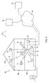
- Fig. 3 shows an overall power management system 30.
- a certain site for example a house 39 having floors 39a, 39b, 39c, one or more power supply apparatuses 10 as described above may be installed. They may be built-in or portable or both. They have interfaces 18 for communicating with a local hub 33.
- the hub may have a gateway function in that it runs a certain protocol towards the power supply apparatuses 10 and runs another protocol towards external. This other protocol may be an internet protocol.
- Hub 33 is connected to a data communication structure such as a data net or data line.
- 32 symbolizes a data net, for example the internet.
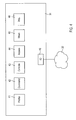
- 31 symbolizes a power management server, shown schematically in fig. 4 .
- 36 symbolizes other data sources, accessible through data communication, e. g. through the internet. 35 symbolizes a terminal of someone having relation to the site 39 and/or to power consumption there.
- the various power supply apparatuses 10 may, through their respective interface 18, be in communication with hub 33 and exchange data with said hub.
- Data transmitted from the respective apparatuses 10 to the hub 33 may be status data, switching report data (reporting about switching on or switching off certain taps), characteristics data, alarm data, savings data, settings data, for example reflecting settings rendered by the assignment section 203, identification data, display data, threshold data, learned data, sensor data.
- Such data may be transmitted towards power management server 31 for storage, processing and evaluation there.
- these data are provided with identification information from identification means 202 so that each apparatus 10 and possibly each tap within each apparatus 10 can individually be monitored and addressed.
- Server 31 can in response to the received data, generate data and transmit them to hub 33 which in turn may, in accordance with identification information, send them to respectively concerned power supply apparatuses.
- Data transmitted from the management server to one of the power supply apparatuses 10 may be control data, command data, settings data, threshold data, pricing data, and the like. Server 31 may generate such data in more complex routines and based on broader knowledge than what would be administratable and feasible within a power supply apparatus 10 itself.
- the power management server 31 may have in input/output section 40. It may have access to other web servers 36 for getting information therefrom.
- 35. denotes a user console. It may be at the site of the power storage apparatuses 10. A user may influence the overall system through this console 35, internet 32, management server 31 and back to hub 33 and the power supply apparatuses 10. However, there may also be a direct connection between terminal 35 and hub 33 without taking the way to and from power management server 31.
- server 31 can establish power consumption profiles for the respective apparatuses 10 or for the individual taps 8 therein through profiling means 41.
- profiles may be power level profiles suitable for finding thresholds, or may be time profiles.
- the profiles may also be kinds of already mentioned finger prints profiles upon switching on suitable for identifying a device based on its switch-on characteristics, such an identification again being suitable, for example, for finding threshold values for switching switches 14 and 15 of the power supply apparatuses 10.
- commands or other control parameters may be generated in command generating means 42 and may be sent to apparatus 10 from which the profiled data came.
- the server 31 may make the same or corresponding determinations as the power supply apparatus 10 and may generate the same or corresponding commands and settings as those described for apparatus 10 or its control means 11, and send them to the power supply apparatus 10. It may thus have the function of control means 11 provided at a remote location.
- server 31 and apparatus 10 may be adapted to respectively send and receive data reflecting control algorithms or strategies.
- the server 31 may send to the apparatus 10, for example, updated thresholds or control algorithms (program data, sub-routine data, task data) for appropriate installation and use there.
- the power management server 31 may have information compiling means 43 for compiling the received information from the various power supply apparatuses 10 and make them accessible by access means 44. This may, of course, be subject to user and password input. But the mentioned compilation may involve complex evaluations, a graphical user interface for making settings, and the like. Likewise, through this mechanism, commands can be given through input means 45 directly at the server or through a user terminal 35 or other terminals. As far as such installations employ the internet and management server 31, commands can be given possibly form anywhere, provided that login into the system and for the particular site is possible. Server 31 may be provided with, or have access to, appropriate memories or data bases 45 for reading and writing data.
- the data path within site 39 may be more complex than shown in Fig. 3 .
- Fig. 5 shows very basic power management methods.
- Fig. 5a shows a local control method, implemented in apparatus 10.
- step 52 data are acquired. This may be done within apparatus 10 by control means 11 and acquiring at least power consumption data from sensors 19, and possibly also occupation data from occupation sensors 12.
- Clock data and ID data from clock 28 and identification means 202 may also be acquired
- step 53 a certain criterion or sets of criteria are checked. Particularly, they may be checked for whether disconnecting a tap 8 from power supply shall be done. If it is found that disconnection shall be made, such disconnection is commanded in step 54. If the criteria for switching off are not met, the procedure ends directly.
- step 53 particular criteria or combined criteria can be checked for.
- a particular check may be whether plural taps (as far as possibly occupied and as far as assigned for evaluation and not exempted from control by assignment means 203) qualify each individually for disconnection (i.e. showing standby power consumption, possibly for more than a predetermined time). If said plurality of taps show such a behavior and qualify individually for switching off, they may all be switched off, i.e. disconnected from power supply by opening the respective switches 15 through appropriate commands (step 55).
- Fig. 5b shows a short flow for remote information, implemented in apparatus 10.
- data are acquired. They may be the same and/or others than those mentioned with respect to fig. 5a . Thereafter, they may be compiled and shaped and formatted for sending in step 56, and in step 57, they may be sent out by apparatus 10 through its interface 18. Thereafter, this flow is terminated (step 55).
- Fig. 5c shows a remote control method, implemented in apparatus.
- control data are received from remote. They may be received in interface 18 of apparatus 10 from management server 31 and/or from user terminal 35.
- the data are stored and/or, depending on their nature, executed. They may go through a command balancing section 29 for resolving possible conflicts with internally generated corresponding data.
- the described apparatuses, computers, systems and methods allow a fine adapted system for power control.
- the occurrences of mismatch of the respectively taken measures are lower. Users can make particular settings according to their needs.
- the claimed invention allows significant power and money savings while preserving user comfort.
Landscapes
- Engineering & Computer Science (AREA)
- General Engineering & Computer Science (AREA)
- Theoretical Computer Science (AREA)
- Power Engineering (AREA)
- Computer Hardware Design (AREA)
- Physics & Mathematics (AREA)
- General Physics & Mathematics (AREA)
- Remote Monitoring And Control Of Power-Distribution Networks (AREA)
Applications Claiming Priority (1)
| Application Number | Priority Date | Filing Date | Title |
|---|---|---|---|
| DE102007048923A DE102007048923A1 (de) | 2007-10-12 | 2007-10-12 | Leistungszuführungsvorrichtung Leistungsmanagement-Server Leistungsmanagement-System Leistungszuführungsverfahren |
Publications (1)
| Publication Number | Publication Date |
|---|---|
| EP2048758A2 true EP2048758A2 (de) | 2009-04-15 |
Family
ID=40404329
Family Applications (1)
| Application Number | Title | Priority Date | Filing Date |
|---|---|---|---|
| EP08002880A Withdrawn EP2048758A2 (de) | 2007-10-12 | 2008-02-15 | Stromversorgungsvorrichtung, Stromverwaltungsserver, Stromverwaltungssystem, Stromversorgungsverfahren |
Country Status (2)
| Country | Link |
|---|---|
| EP (1) | EP2048758A2 (de) |
| DE (1) | DE102007048923A1 (de) |
Cited By (7)
| Publication number | Priority date | Publication date | Assignee | Title |
|---|---|---|---|---|
| TWI454895B (zh) * | 2009-07-07 | 2014-10-01 | Inventec Corp | 伺服器的電源供應裝置 |
| ITBA20130053A1 (it) * | 2013-07-03 | 2015-01-04 | Giacomo Pedote | Presa multipla per la sicurezza elettrica e il risparmio energetico |
| CN107797005A (zh) * | 2017-09-28 | 2018-03-13 | 郑州云海信息技术有限公司 | 一种适用于多psu服务器的智能疲劳测试机 |
| JP2019024239A (ja) * | 2018-10-09 | 2019-02-14 | 株式会社Crossdoor | 遠隔制御システムおよびサーバ |
| WO2019159089A1 (en) * | 2018-02-19 | 2019-08-22 | Landis+Gyr Ag | Device, system and method for controlling electrical loads |
| EP3582340A1 (de) * | 2018-06-12 | 2019-12-18 | Rheinisch-Westfälische Technische Hochschule (RWTH) Aachen | Adaptier geräteanschluss |
| CN114421500A (zh) * | 2022-02-11 | 2022-04-29 | 华北电力大学(保定) | 一种多直流馈入受端电网的主动解列断面确定方法 |
Families Citing this family (3)
| Publication number | Priority date | Publication date | Assignee | Title |
|---|---|---|---|---|
| DE102014107800A1 (de) * | 2014-06-03 | 2015-12-03 | Markus Lawrenz | Steuerungsvorrichtung, Steckeradapter und System mit mindestens zwei Steuerungsvorrichtungen |
| DE102015100040B4 (de) * | 2015-01-05 | 2018-12-27 | Stefan Borchert | Mehrfachsteckdosensystem und Verfahren zum Betrieb desselben |
| DE102020128445A1 (de) | 2020-10-29 | 2022-05-05 | Jürgen Winkler | Intelligente-Sicherheits-Einrichtung für eine Stromversorgung |
-
2007
- 2007-10-12 DE DE102007048923A patent/DE102007048923A1/de not_active Withdrawn
-
2008
- 2008-02-15 EP EP08002880A patent/EP2048758A2/de not_active Withdrawn
Cited By (9)
| Publication number | Priority date | Publication date | Assignee | Title |
|---|---|---|---|---|
| TWI454895B (zh) * | 2009-07-07 | 2014-10-01 | Inventec Corp | 伺服器的電源供應裝置 |
| ITBA20130053A1 (it) * | 2013-07-03 | 2015-01-04 | Giacomo Pedote | Presa multipla per la sicurezza elettrica e il risparmio energetico |
| CN107797005A (zh) * | 2017-09-28 | 2018-03-13 | 郑州云海信息技术有限公司 | 一种适用于多psu服务器的智能疲劳测试机 |
| WO2019159089A1 (en) * | 2018-02-19 | 2019-08-22 | Landis+Gyr Ag | Device, system and method for controlling electrical loads |
| CH714695A1 (de) * | 2018-02-19 | 2019-08-30 | Landis & Gyr Ag | Vorrichtung, System und Verfahren zum Steuern elektrischer Lasten. |
| US11770003B2 (en) | 2018-02-19 | 2023-09-26 | Landis+Gyr Ag | Device, system and method for controlling electrical loads |
| EP3582340A1 (de) * | 2018-06-12 | 2019-12-18 | Rheinisch-Westfälische Technische Hochschule (RWTH) Aachen | Adaptier geräteanschluss |
| JP2019024239A (ja) * | 2018-10-09 | 2019-02-14 | 株式会社Crossdoor | 遠隔制御システムおよびサーバ |
| CN114421500A (zh) * | 2022-02-11 | 2022-04-29 | 华北电力大学(保定) | 一种多直流馈入受端电网的主动解列断面确定方法 |
Also Published As
| Publication number | Publication date |
|---|---|
| DE102007048923A1 (de) | 2009-04-16 |
Similar Documents
| Publication | Publication Date | Title |
|---|---|---|
| EP2048758A2 (de) | Stromversorgungsvorrichtung, Stromverwaltungsserver, Stromverwaltungssystem, Stromversorgungsverfahren | |
| US20250174946A1 (en) | Techniques For Integrating Wireless Functionality In A Power Outlet | |
| US9634738B2 (en) | Hybrid power line/wireless appliance automation system, device, and power monitoring method utilizing the same | |
| US9106099B2 (en) | Power monitoring system | |
| CA2911354C (en) | Load power device, system and method of load control and management employing load identification | |
| CN102870307B (zh) | 电流供给模块 | |
| WO2008035322A1 (en) | A retrofitting power distribution device and uses thereof | |
| KR101035127B1 (ko) | 원격제어 가능한 절전형 콘센트 장치 | |
| US11664679B2 (en) | Communication circuit for 2-wire protocols between HVAC systems and smart-home devices | |
| US8818532B1 (en) | System and method for selectively controlling and monitoring receptacles and fixtures connected to a power circuit in a building | |
| KR101864608B1 (ko) | 상황인식 에너지 관리용 스마트 콘센트 서비스 방법 및 시스템 | |
| KR102327693B1 (ko) | 콘센트 장치 및 이를 포함하는 콘센트 시스템 | |
| US11855712B2 (en) | Power extender for smart-home controllers using 2-wire communication | |
| JP2008219957A (ja) | 家電機器遠隔制御システム | |
| KR20060021758A (ko) | 원격 전원 제어 방법 및 그 장치 | |
| FI128767B (en) | Electrical outlet system and procedure for electrical outlet system | |
| CN215527998U (zh) | 一种排插插座 | |
| KR20210019875A (ko) | 전력선 통신을 활용한 저가형 빌딩 자동화 시스템 | |
| NL2008478C2 (en) | Plc control of appliances identified by current analysis. | |
| CN113161790A (zh) | 一种排插插座 | |
| KR20060115113A (ko) | 전원제어기능이 구비된 홈게이트웨이 및 이의 제어방법 | |
| IT202100014573A1 (it) | Sistema modulare per domotica | |
| CN112787169A (zh) | 一种墙面插座 | |
| WO2010056407A1 (en) | Apparatus and method for providing operative power to powerline-network device |
Legal Events
| Date | Code | Title | Description |
|---|---|---|---|
| PUAI | Public reference made under article 153(3) epc to a published international application that has entered the european phase |
Free format text: ORIGINAL CODE: 0009012 |
|
| 17P | Request for examination filed |
Effective date: 20080331 |
|
| AK | Designated contracting states |
Kind code of ref document: A2 Designated state(s): AT BE BG CH CY CZ DE DK EE ES FI FR GB GR HR HU IE IS IT LI LT LU LV MC MT NL NO PL PT RO SE SI SK TR |
|
| AX | Request for extension of the european patent |
Extension state: AL BA MK RS |
|
| STAA | Information on the status of an ep patent application or granted ep patent |
Free format text: STATUS: THE APPLICATION HAS BEEN WITHDRAWN |
|
| 18W | Application withdrawn |
Effective date: 20100610 |