EP2048363A2 - Scroll compressor with scroll deflection compensation - Google Patents
Scroll compressor with scroll deflection compensation Download PDFInfo
- Publication number
- EP2048363A2 EP2048363A2 EP08251207A EP08251207A EP2048363A2 EP 2048363 A2 EP2048363 A2 EP 2048363A2 EP 08251207 A EP08251207 A EP 08251207A EP 08251207 A EP08251207 A EP 08251207A EP 2048363 A2 EP2048363 A2 EP 2048363A2
- Authority
- EP
- European Patent Office
- Prior art keywords
- scroll
- scroll member
- cavity
- passageway
- fluid
- Prior art date
- Legal status (The legal status is an assumption and is not a legal conclusion. Google has not performed a legal analysis and makes no representation as to the accuracy of the status listed.)
- Withdrawn
Links
- 239000012530 fluid Substances 0.000 claims abstract description 78
- 230000006835 compression Effects 0.000 claims description 20
- 238000007906 compression Methods 0.000 claims description 20
- 238000000034 method Methods 0.000 claims description 12
- 230000033001 locomotion Effects 0.000 claims description 4
- 238000007599 discharging Methods 0.000 claims 1
- 230000002093 peripheral effect Effects 0.000 claims 1
- 238000005452 bending Methods 0.000 abstract description 9
- 238000007789 sealing Methods 0.000 description 6
- 230000008878 coupling Effects 0.000 description 5
- 238000010168 coupling process Methods 0.000 description 5
- 238000005859 coupling reaction Methods 0.000 description 5
- 238000007667 floating Methods 0.000 description 4
- 230000003993 interaction Effects 0.000 description 2
- 239000000314 lubricant Substances 0.000 description 2
- 239000003507 refrigerant Substances 0.000 description 2
- 238000000926 separation method Methods 0.000 description 2
- 230000002411 adverse Effects 0.000 description 1
- 230000008901 benefit Effects 0.000 description 1
- 230000001351 cycling effect Effects 0.000 description 1
- 230000003467 diminishing effect Effects 0.000 description 1
- 230000006872 improvement Effects 0.000 description 1
- 230000001050 lubricating effect Effects 0.000 description 1
- 238000005461 lubrication Methods 0.000 description 1
- 239000000463 material Substances 0.000 description 1
- 230000000704 physical effect Effects 0.000 description 1
- 230000004044 response Effects 0.000 description 1
- 238000004804 winding Methods 0.000 description 1
Images
Classifications
-
- F—MECHANICAL ENGINEERING; LIGHTING; HEATING; WEAPONS; BLASTING
- F04—POSITIVE - DISPLACEMENT MACHINES FOR LIQUIDS; PUMPS FOR LIQUIDS OR ELASTIC FLUIDS
- F04C—ROTARY-PISTON, OR OSCILLATING-PISTON, POSITIVE-DISPLACEMENT MACHINES FOR LIQUIDS; ROTARY-PISTON, OR OSCILLATING-PISTON, POSITIVE-DISPLACEMENT PUMPS
- F04C18/00—Rotary-piston pumps specially adapted for elastic fluids
- F04C18/02—Rotary-piston pumps specially adapted for elastic fluids of arcuate-engagement type, i.e. with circular translatory movement of co-operating members, each member having the same number of teeth or tooth-equivalents
- F04C18/0207—Rotary-piston pumps specially adapted for elastic fluids of arcuate-engagement type, i.e. with circular translatory movement of co-operating members, each member having the same number of teeth or tooth-equivalents both members having co-operating elements in spiral form
- F04C18/0215—Rotary-piston pumps specially adapted for elastic fluids of arcuate-engagement type, i.e. with circular translatory movement of co-operating members, each member having the same number of teeth or tooth-equivalents both members having co-operating elements in spiral form where only one member is moving
-
- F—MECHANICAL ENGINEERING; LIGHTING; HEATING; WEAPONS; BLASTING
- F04—POSITIVE - DISPLACEMENT MACHINES FOR LIQUIDS; PUMPS FOR LIQUIDS OR ELASTIC FLUIDS
- F04C—ROTARY-PISTON, OR OSCILLATING-PISTON, POSITIVE-DISPLACEMENT MACHINES FOR LIQUIDS; ROTARY-PISTON, OR OSCILLATING-PISTON, POSITIVE-DISPLACEMENT PUMPS
- F04C23/00—Combinations of two or more pumps, each being of rotary-piston or oscillating-piston type, specially adapted for elastic fluids; Pumping installations specially adapted for elastic fluids; Multi-stage pumps specially adapted for elastic fluids
- F04C23/008—Hermetic pumps
-
- F—MECHANICAL ENGINEERING; LIGHTING; HEATING; WEAPONS; BLASTING
- F04—POSITIVE - DISPLACEMENT MACHINES FOR LIQUIDS; PUMPS FOR LIQUIDS OR ELASTIC FLUIDS
- F04C—ROTARY-PISTON, OR OSCILLATING-PISTON, POSITIVE-DISPLACEMENT MACHINES FOR LIQUIDS; ROTARY-PISTON, OR OSCILLATING-PISTON, POSITIVE-DISPLACEMENT PUMPS
- F04C27/00—Sealing arrangements in rotary-piston pumps specially adapted for elastic fluids
- F04C27/005—Axial sealings for working fluid
Definitions
- the present teachings relate generally to scroll machines such as scroll compressors and, more particularly, to scroll compressors with scroll deflection compensation.
- a scroll compressor can compress a fluid from a suction pressure to a discharge pressure greater than the suction pressure.
- the scroll compressor can use a non-orbiting scroll member and an orbiting scroll member, each having wraps positioned in meshing engagement with one another.
- the relative movement between the scroll members causes the fluid pressure to increase as the fluid moves from the suction port to the discharge port.
- the orbiting and fixed scroll members are designed to be in a uniform, but light, contact with each other to maintain sealing therebetween.
- the base plates of the fixed and orbiting scroll members can experience axial deformations due to high fluid pressure present in the compression chambers formed by the intermeshing wraps.
- the axial deformations can be more pronounced at locations corresponding to higher fluid pressure.
- the wraps of both the fixed and orbiting scroll members may experience thermal growth due to contact with the hot compressed fluid in the compression chambers.
- the thermal growth can be more pronounced in locations corresponding to higher fluid temperature.
- the axial deformations and/or thermal growth may adversely impact the ability to maintain sealing between the scroll members.
- a scroll compressor according to the present teachings may incorporate controlled bending of the fixed scroll member to compensate for the deformations during operation.
- the controlled bending may be achieved through the use of fluid pressure in a sealed chamber that communicates with the fixed scroll member. Fluid passageways can extend through the fixed scroll member between the sealed chamber and the intermeshing orbiting scroll member.
- the controlled bending can increase the uniformity of the contact between the scroll members and thereby improve the efficiency of the compressing operation.
- a method of operating a scroll compressor according to the present teachings can include the varying of the fluid pressure in a cavity on a non-intermeshed side of the non-orbiting scroll member to cause controlled bending of the non-orbiting scroll member and compensate for deformation to one or both of the scroll members due to compression of a working fluid.
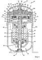
- Figure 1 is a cross-sectional view of a scroll compressor according to the present teachings
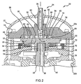
- Figure 2 is an enlarged fragmented view of a portion of the compressor of Figure 1 showing details of the fixed and orbiting scroll members;
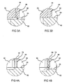
- Figures 3A and 3B are enlarged exemplary fragmented views of the interaction of the fixed and orbiting scroll members within circle 3 of Figure 2 in a non-sealed and sealed state according to the present teachings;
- Figures 4A and 4B are enlarged exemplary fragmented views of the interaction of the fixed and orbiting scroll members within circle 4 of Figure 2 in a sealed and non-sealed state according to the present teachings.
- Compressor 20 comprises a shell 22 having an upper portion 22a that is attached to a lower portion 22b in a sealed relationship.
- Shell 22 can be generally cylindrical.
- Upper shell 22a is provided with a refrigerant discharge port 24 through which a refrigerant discharge passage 26 extends.
- a stationary main bearing housing or body 28 and a lower bearing assembly 30 are secured in shell 22.
- a driveshaft or crankshaft 32 having an eccentric crankpin 34 at the upper end thereof is rotatably journaled in main bearing housing 28 and in lower bearing assembly 30.
- Crankshaft 32 has at the lower end a relatively large diameter concentric bore 36 which communicates with a radially outwardly inclined small diameter bore 38 extending upwardly therefrom to the top of crankshaft 32. Disposed within bore 36 is a stirrer 40.
- the lower portion of lower shell 22b forms a sump which is filled with lubricant and bore 36 can act as a pump to pump lubricating fluid up crankshaft 32 and into bore 38 and ultimately to various portions of the compressor that require lubrication.
- a strainer 42 is attached to the lower portion of shell 22b and directs the lubricant flow into bore 36.
- Crankshaft 32 is rotatably driven by an electric motor 44 disposed within lower bearing assembly 30.
- Electric motor 44 includes a stator 46, windings 48 passing therethrough, and a rotor 50 rigidly mounted on crankshaft 32.
- the upper surface of main bearing housing 28 includes a flat thrust-bearing surface 52 with an axially extending recess 54 therein.
- a floating seal 56 is disposed in recess 54.
- Thrust-bearing surface 52 and floating seal 56 axially support a lower surface 60 of an orbiting scroll member 62.
- Orbiting scroll member 62 includes a spiral vane or wrap 64 extending axially upwardly from an upper surface 65 thereof.
- Projecting downwardly from lower surface 60 of orbiting scroll member 62 is a cylindrical hub 66 having a journal bearing 68 and a drive bushing 70 therein and within which crankpin 34 is drivingly disposed.
- Crankpin 34 has a flat on one surface that drivingly engages a flat surface (not shown) formed in a portion of drive bushing 70 to provide a radially compliant drive arrangement, such as shown in Assignee's U.S. Patent No. 4,877,382 , entitled “Scroll-Type Machine with Axially Compliant Mounting," the disclosure of which is herein incorporated by reference.
- An Oldham coupling 72 can be positioned between and keyed to orbiting scroll member 62 and bearing housing 28 to prevent rotational movement of orbiting scroll member 62. Oldham coupling 72 may be of the type disclosed in the above-referenced U.S. Patent No.
- a non-orbiting scroll member 76 is stationarily secured within shell 22.
- Non-orbiting scroll member 76 can be secured to main bearing housing 28 with bolts 78.
- Main bearing housing 28 can provide axial support for the periphery of non-orbiting scroll member 76.
- a seal 80 can extend between upper shell 22a and the side of non-orbiting scroll member 76 to form a seal therebetween.
- a cavity 82 can be disposed above upper surface 84 of non-orbiting scroll member 76. Cavity 82 can be defined by upper surface 84 and upper shell 22a.
- Non-orbiting scroll member 76 includes opposite upper and lower surfaces 84, 86.
- Lower surface 86 includes a spiral vane or wrap 88 that extends axially downwardly and is in meshing engagement with wrap 64 of orbiting scroll member 62.
- Non-orbiting scroll member 76 has a centrally disposed discharge passage/port 90 that communicates with discharge passage 26 to direct compressed fluid out of scroll compressor 20.
- a discharge valve (not shown) may be disposed in discharge passage 90 and/or discharge passage 26. The discharge valve can be a one-way valve.
- Discharge passage 26 is disposed in discharge port 90 in a sealed manner that prevents fluid flowing through discharge port 90 and discharge passageway 26 from communicating with fluid in cavity 82 and can allow some relative axial motion between discharge passage 26 and non-orbiting scroll member 76.
- Orbiting scroll member 62 can orbit relative to non-orbiting scroll member 76 and cause the respective wraps 64, 88 to move relative to one another and form compression cavities/pockets 92 which progressively diminish in volume to compress the fluid therein.
- a plurality of compression cavities 92 is formed between wraps 64, 88.
- the fluid is sucked into the scroll set at a suction pressure adjacent the periphery of orbiting scroll member 62.
- the fluid is then compressed to the discharge pressure by the progressively diminishing size of compression cavities 92 and is discharged through discharge passage 90 in the center of non-orbiting scroll member 76.
- axial support for orbiting scroll member 62 is provided by floating seal 56 and thrust-bearing surface 52.
- Floating seal 56 and thrust-bearing surface 52 are located near the periphery of orbiting scroll member 62.
- orbiting scroll member 62 can experience bending such that upper surface 65 becomes concave (deformed downwardly in the view depicted in Figure 2 ), especially near the center.
- non-orbiting scroll member 76 is axially supported by bearing housing 28 adjacent the periphery and the higher pressure adjacent the center of non-orbiting scroll member 76 can cause lower surface 86 to also bend and become concave (deformed upwardly in the view depicted in Figure 2 ).
- the deflection of the central portion of orbiting scroll member 62 (downward in the view depicted in Figure 2 ) can be about 15-20 microns, relative to the periphery of orbiting scroll member 62, by way of non-limiting example.
- the deflection of the central portion of fixed scroll member 76 can be about 10-15 microns (upwards in the view depicted in Figure 2 ) relative to the periphery of fixed scroll member 76, by way of non-limiting example.
- the temperature of the compressed fluid also increases from the periphery toward the center of non-orbiting scroll member 76.
- the increasing temperature can cause wraps 64, 88 to experience thermal growth with the higher growth occurring in the centers of scroll members 62, 76 and lesser growth occurring around the periphery.
- Thermal growth may vary from about 0.5 microns on the scroll periphery to about 10 microns in the zone adjacent to the scroll center, by way of non-limiting example. Thermal growth of the wraps occurs in the direction away from the respective base plate.
- wrap 64 of orbiting scroll member 62 grows upwards (in the view depicted in Figure 2 ) from upper surface 65, while wrap 88 of non-orbiting scroll member 76 grows downwards (in the view depicted in Figure 2 ) from lower surface 86.
- fluid pressure in cavity 82 can be utilized to cause desirable bending or deformation of non-orbiting scroll member 76 to compensate for the undesirable deformation that can occur.
- the compensation can improve the sealing between the tips of wraps 64, 88 and the associated lower surface 86 of non-orbiting scroll member 76 and upper surface 65 of orbiting scroll member 62.
- this can be achieved by providing a high-pressure passageway 96 and a low-pressure passageway 98 that communicate with cavity 82 and extend through non-orbiting scroll member 76 to orbiting scroll member 62.
- high-pressure passageway 96 can be disposed adjacent discharge passage 90 and can extend through non-orbiting scroll member 76 from cavity 82 through wrap 88 adjacent discharge passage 90.
- Low-pressure passageway 98 can extend through non-orbiting scroll member 76 from cavity 82 through wrap 88 adjacent the periphery of orbiting scroll member 62.
- High-pressure passageway 96 and low-pressure passageway 98 can allow the fluid being compressed by compressor 20 to flow between the compression cavities 92 and cavity 82 in response to deformation of scroll members 62, 76 and compensate for the undesirable deformation, as described below.
- the inner diameter of passageways 96, 98 can be about one millimeter.
- high-pressure fluid in cavity 92 and discharge passage 90 adjacent wrap 88 containing high-pressure passageway 96 can travel through high-pressure passageway 96 and into cavity 82.
- the pressure in cavity 82 can increase up to a maximum of the discharge pressure of compressor 20 as fluid flows therein from high-pressure passageway 96.
- the increase in pressure in cavity 82 can cause the central portion of non-orbiting scroll member 76 to deform (downwardly in the views depicted) such that the wrap 88 through which high-pressure passageway 96 extends engages with upper surface 65 of orbiting scroll member 62, as shown in Figure 4A , and seals high-pressure passageway 96.
- low-pressure passageway 98 As the pressure in cavity 82 continues to decrease as the fluid flows through low-pressure passageway 98, the deformation of the central part of non-orbiting scroll member 76 can decrease and eventually result in low-pressure passageway 98 being sealed by the tips of the associated wrap 88 engaging with upper surface 65 of orbiting scroll member 62, as shown in Figure 3B . At that time, high-pressure passageway 96 may also still remain sealed, as shown in Figure 4A or possibly re-open as shown in Figure 4B .
- the high-pressure passageway 96 if not already re-opened, can again open due to separation between the wrap 88 associated with high-pressure passageway 96 disengaging from the upper surface 65 of orbiting scroll member 62 due to the fluid pressure therebetween and the thermal growth of wrap 88.
- fluid can flow from compression cavity 92 adjacent high-pressure passageway 96 and from discharge passage 90 into cavity 82 to again increase the pressure in cavity 82 and start the compensation cycle over again.
- the compensation cycle can continue to operate as compressor 20 is operated and the fluid being compressed therein causes axial deformation of the central parts of orbiting and non-orbiting scroll members 62, 76 and thermal growth of the associated wraps 64, 88.
- the pressure in cavity 82 will vary as high and low-pressure passageways 96, 98 are open and closed due to the compensation for the deformation.
- the cycling of the opening and closing of passageways 96, 98 can result in increased sealing between wraps 64, 88 such that an overall improvement in efficiency of compressor 20 is realized.
- non-orbiting scroll member 76 can influence the amount of deformation that occurs during operation of compressor 20 and, accordingly, can be selected such that their deformation is within an operational envelope wherein proper compensation can be achieved by altering the pressure in cavity 82 through the use of high and low-pressure passageways 96, 98.
- the pressure in cavity 82 can vary from discharge pressure to suction pressure depending upon the location of high and low-pressure passageways 96, 98 and the operational gaps between orbiting and non-orbiting scroll members 62, 76 at these locations through which passageways 96, 98 communicate with the working fluid.
- the location of axial supports for orbiting and non-orbiting scroll members 62, 76 can also affect the deformation that the scroll members incur. As such, the selection of the materials, dimensions, stiffness, location and quantity of supports, along with the number and size of high and low-pressure passageways 96, 98, can influence the ability of varying pressure in cavity 82 to compensate for deformations in orbiting and non-orbiting scroll members 62, 76.
- a scroll compressor with scroll deflection compensation can utilize high and low-pressure passageways 96, 98 that extend through non-orbiting scroll member 76 to allow fluid pressure in a cavity 82 that acts on the upper surface 84 of non-orbiting scroll member 76 to compensate for axial deformations and thermal growth of the associated wraps.
- the number, size, and location of high and low-pressure passageways 96, 98 can be chosen to provide a desired compensation.
- the dimensions and stiffness of scroll members 62, 76 and the location of axial supports therefore can also be chosen to work in conjunction with high and low-pressure passageways 96, 98 to allow the pressure in cavity 82 to compensate for the deformation and thermal growth.
- increased sealing contact between the tips of wraps 88, 64 and the associated upper and lower surfaces 65, 86 of the respective orbiting scroll member 62 and non-orbiting scroll member 76 can be improved thereby improving the overall efficiency of compressor 20.
- compressor 20 can take various forms and still be within the scope of the present teachings. Additionally, it should also be appreciated that the dimensions shown herein are for exemplary purposes only and may not reflect actual dimensions, relative or absolute, and, in some cases, may be exaggerated. Moreover, the location, number, and size of passageways 96, 98 are merely exemplary and changes in the location, size, and number can be employed without departing from the spirit and scope of the present teachings. It should be appreciated that it may be possible to include high and low pressure passageways that extend through orbiting scroll member 62 and communicate with a sealed cavity to allow orbiting scroll member 62 to compensate for the undesirable deformation.
Landscapes
- Engineering & Computer Science (AREA)
- Mechanical Engineering (AREA)
- General Engineering & Computer Science (AREA)
- Rotary Pumps (AREA)
- Applications Or Details Of Rotary Compressors (AREA)
Abstract
A scroll compressor may incorporate controlled bending of a scroll member to compensate for axial deformations that can occur between the scroll members. The controlled bending may be through the use of fluid pressure in a sealed chamber that communicates with a surface of the scroll member opposite the intermeshing wraps. Fluid passageways can extend through the scroll member between the sealed chamber and the intermeshing wraps. The controlled bending can increase the uniformity of the contact between the scroll members and improve the efficiency of the compressing operation.
Description
- This application claims the benefit of
U.S. Provisional Application No. 60/979,543, filed on October 12, 2007 - The present teachings relate generally to scroll machines such as scroll compressors and, more particularly, to scroll compressors with scroll deflection compensation.
- The statements in this section merely provide background information related to the present teachings and may not constitute prior art.
- A scroll compressor can compress a fluid from a suction pressure to a discharge pressure greater than the suction pressure. The scroll compressor can use a non-orbiting scroll member and an orbiting scroll member, each having wraps positioned in meshing engagement with one another. The relative movement between the scroll members causes the fluid pressure to increase as the fluid moves from the suction port to the discharge port. To improve efficiency, the orbiting and fixed scroll members are designed to be in a uniform, but light, contact with each other to maintain sealing therebetween.
- During operation, however, the base plates of the fixed and orbiting scroll members can experience axial deformations due to high fluid pressure present in the compression chambers formed by the intermeshing wraps. The axial deformations can be more pronounced at locations corresponding to higher fluid pressure. Additionally, the wraps of both the fixed and orbiting scroll members may experience thermal growth due to contact with the hot compressed fluid in the compression chambers. The thermal growth can be more pronounced in locations corresponding to higher fluid temperature. The axial deformations and/or thermal growth may adversely impact the ability to maintain sealing between the scroll members.
- A scroll compressor according to the present teachings may incorporate controlled bending of the fixed scroll member to compensate for the deformations during operation. The controlled bending may be achieved through the use of fluid pressure in a sealed chamber that communicates with the fixed scroll member. Fluid passageways can extend through the fixed scroll member between the sealed chamber and the intermeshing orbiting scroll member. The controlled bending can increase the uniformity of the contact between the scroll members and thereby improve the efficiency of the compressing operation. A method of operating a scroll compressor according to the present teachings can include the varying of the fluid pressure in a cavity on a non-intermeshed side of the non-orbiting scroll member to cause controlled bending of the non-orbiting scroll member and compensate for deformation to one or both of the scroll members due to compression of a working fluid.
- Further areas of applicability will become apparent from the description provided herein. It should be understood that the description and specific examples are intended for purposes of illustration only and are not intended to limit the scope of the present claims.
- The drawings described herein are for illustration purposes only and are not intended to limit the scope of the present teachings in any way.
-
Figure 1 is a cross-sectional view of a scroll compressor according to the present teachings; -
Figure 2 is an enlarged fragmented view of a portion of the compressor ofFigure 1 showing details of the fixed and orbiting scroll members; -
Figures 3A and 3B are enlarged exemplary fragmented views of the interaction of the fixed and orbiting scroll members within circle 3 ofFigure 2 in a non-sealed and sealed state according to the present teachings; and -
Figures 4A and 4B are enlarged exemplary fragmented views of the interaction of the fixed and orbiting scroll members within circle 4 ofFigure 2 in a sealed and non-sealed state according to the present teachings. - The following description is merely exemplary in nature and is not intended to limit the present disclosure, application, or uses.
- Referring to
Figures 1 and2 , anexemplary scroll compressor 20 according to the present teachings is shown.Compressor 20 comprises ashell 22 having anupper portion 22a that is attached to alower portion 22b in a sealed relationship.Shell 22 can be generally cylindrical.Upper shell 22a is provided with arefrigerant discharge port 24 through which arefrigerant discharge passage 26 extends. A stationary main bearing housing orbody 28 and alower bearing assembly 30 are secured inshell 22. A driveshaft orcrankshaft 32 having aneccentric crankpin 34 at the upper end thereof is rotatably journaled in main bearinghousing 28 and inlower bearing assembly 30.Crankshaft 32 has at the lower end a relatively large diameterconcentric bore 36 which communicates with a radially outwardly inclinedsmall diameter bore 38 extending upwardly therefrom to the top ofcrankshaft 32. Disposed withinbore 36 is astirrer 40. The lower portion oflower shell 22b forms a sump which is filled with lubricant andbore 36 can act as a pump to pump lubricating fluid upcrankshaft 32 and intobore 38 and ultimately to various portions of the compressor that require lubrication. Astrainer 42 is attached to the lower portion ofshell 22b and directs the lubricant flow intobore 36. -
Crankshaft 32 is rotatably driven by anelectric motor 44 disposed withinlower bearing assembly 30.Electric motor 44 includes astator 46,windings 48 passing therethrough, and arotor 50 rigidly mounted oncrankshaft 32. - The upper surface of main bearing
housing 28 includes a flat thrust-bearingsurface 52 with an axially extendingrecess 54 therein. A floatingseal 56 is disposed inrecess 54. Thrust-bearingsurface 52 and floatingseal 56 axially support alower surface 60 of an orbitingscroll member 62.Orbiting scroll member 62 includes a spiral vane orwrap 64 extending axially upwardly from anupper surface 65 thereof. Projecting downwardly fromlower surface 60 of orbitingscroll member 62 is acylindrical hub 66 having a journal bearing 68 and a drive bushing 70 therein and within which crankpin 34 is drivingly disposed. Crankpin 34 has a flat on one surface that drivingly engages a flat surface (not shown) formed in a portion of drive bushing 70 to provide a radially compliant drive arrangement, such as shown in Assignee'sU.S. Patent No. 4,877,382 , entitled "Scroll-Type Machine with Axially Compliant Mounting," the disclosure of which is herein incorporated by reference. An Oldhamcoupling 72 can be positioned between and keyed to orbitingscroll member 62 and bearinghousing 28 to prevent rotational movement of orbitingscroll member 62. Oldhamcoupling 72 may be of the type disclosed in the above-referencedU.S. Patent No. 4,877,382 ; however, other Oldham couplings, such as the coupling disclosed in Assignee'sU.S. Patent No. 6,231,324 , entitled "Oldham Coupling for Scroll Machine," the disclosure of which is hereby incorporated by reference, may also be used. - A
non-orbiting scroll member 76 is stationarily secured withinshell 22. Non-orbitingscroll member 76 can be secured to main bearinghousing 28 withbolts 78. Main bearinghousing 28 can provide axial support for the periphery ofnon-orbiting scroll member 76. Aseal 80 can extend betweenupper shell 22a and the side ofnon-orbiting scroll member 76 to form a seal therebetween. Acavity 82 can be disposed aboveupper surface 84 ofnon-orbiting scroll member 76.Cavity 82 can be defined byupper surface 84 andupper shell 22a. - Non-orbiting
scroll member 76 includes opposite upper andlower surfaces Lower surface 86 includes a spiral vane orwrap 88 that extends axially downwardly and is in meshing engagement withwrap 64 of orbitingscroll member 62. Non-orbitingscroll member 76 has a centrally disposed discharge passage/port 90 that communicates withdischarge passage 26 to direct compressed fluid out ofscroll compressor 20. A discharge valve (not shown) may be disposed indischarge passage 90 and/ordischarge passage 26. The discharge valve can be a one-way valve.Discharge passage 26 is disposed indischarge port 90 in a sealed manner that prevents fluid flowing throughdischarge port 90 anddischarge passageway 26 from communicating with fluid incavity 82 and can allow some relative axial motion betweendischarge passage 26 and non-orbitingscroll member 76. - Orbiting
scroll member 62 can orbit relative to non-orbitingscroll member 76 and cause therespective wraps pockets 92 which progressively diminish in volume to compress the fluid therein. As best seen inFigure 2 , a plurality ofcompression cavities 92 is formed betweenwraps scroll member 62. The fluid is then compressed to the discharge pressure by the progressively diminishing size ofcompression cavities 92 and is discharged throughdischarge passage 90 in the center ofnon-orbiting scroll member 76. Because the pressure of the fluid being compressed within intermeshing wraps 64, 88 increases as the fluid advances toward the center ofnon-orbiting scroll member 76, the axial force from the compressed fluid is greatestadjacent discharge passage 90 and is lower adjacent the periphery of orbitingscroll member 62 wherein the fluid is at suction pressure. - As stated above, axial support for orbiting
scroll member 62 is provided by floatingseal 56 and thrust-bearingsurface 52. Floatingseal 56 and thrust-bearingsurface 52, however, are located near the periphery of orbitingscroll member 62. As a result, orbitingscroll member 62 can experience bending such thatupper surface 65 becomes concave (deformed downwardly in the view depicted inFigure 2 ), especially near the center. Similarly,non-orbiting scroll member 76 is axially supported by bearinghousing 28 adjacent the periphery and the higher pressure adjacent the center ofnon-orbiting scroll member 76 can causelower surface 86 to also bend and become concave (deformed upwardly in the view depicted inFigure 2 ). The deflection of the central portion of orbiting scroll member 62 (downward in the view depicted inFigure 2 ) can be about 15-20 microns, relative to the periphery of orbitingscroll member 62, by way of non-limiting example. Similarly, the deflection of the central portion offixed scroll member 76 can be about 10-15 microns (upwards in the view depicted inFigure 2 ) relative to the periphery of fixedscroll member 76, by way of non-limiting example. - In addition to the axial-separating forces caused by the fluid pressure between intermeshing wraps 64, 88, the temperature of the compressed fluid also increases from the periphery toward the center of
non-orbiting scroll member 76. The increasing temperature can cause wraps 64, 88 to experience thermal growth with the higher growth occurring in the centers ofscroll members scroll member 62 grows upwards (in the view depicted inFigure 2 ) fromupper surface 65, whilewrap 88 ofnon-orbiting scroll member 76 grows downwards (in the view depicted inFigure 2 ) fromlower surface 86. - The concave deformations of
upper surface 65 of orbitingscroll member 62 andlower surface 86 ofnon-orbiting scroll member 76, in conjunction with the thermal growth ofwraps wraps scroll members compressor 20. - In accordance with the present teachings, fluid pressure in
cavity 82 can be utilized to cause desirable bending or deformation ofnon-orbiting scroll member 76 to compensate for the undesirable deformation that can occur. The compensation can improve the sealing between the tips ofwraps lower surface 86 ofnon-orbiting scroll member 76 andupper surface 65 of orbitingscroll member 62. According to the present teachings, this can be achieved by providing a high-pressure passageway 96 and a low-pressure passageway 98 that communicate withcavity 82 and extend throughnon-orbiting scroll member 76 to orbitingscroll member 62. Specifically, high-pressure passageway 96 can be disposedadjacent discharge passage 90 and can extend throughnon-orbiting scroll member 76 fromcavity 82 throughwrap 88adjacent discharge passage 90. Low-pressure passageway 98 can extend throughnon-orbiting scroll member 76 fromcavity 82 throughwrap 88 adjacent the periphery of orbitingscroll member 62. High-pressure passageway 96 and low-pressure passageway 98 can allow the fluid being compressed bycompressor 20 to flow between thecompression cavities 92 andcavity 82 in response to deformation ofscroll members passageways - During initial operation of
compressor 20, whereinscroll members wraps pressure passageways upper surface 65 of orbitingscroll member 62, as shown inFigures 3B and 4A . As operation ofcompressor 20 continues, the thermal growth ofwraps non-orbiting scroll members pressure passageway 96 being no longer sealed againstupper surface 65 of orbitingscroll member 62, as shown inFigure 4B , while low-pressure passageway 98 remains sealed, as shown inFigure 3B . As a result, high-pressure fluid incavity 92 anddischarge passage 90adjacent wrap 88 containing high-pressure passageway 96 can travel through high-pressure passageway 96 and intocavity 82. The pressure incavity 82 can increase up to a maximum of the discharge pressure ofcompressor 20 as fluid flows therein from high-pressure passageway 96. The increase in pressure incavity 82 can cause the central portion ofnon-orbiting scroll member 76 to deform (downwardly in the views depicted) such that thewrap 88 through which high-pressure passageway 96 extends engages withupper surface 65 of orbitingscroll member 62, as shown inFigure 4A , and seals high-pressure passageway 96. - The resulting deformation of the central part of
non-orbiting scroll member 76 toward orbitingscroll member 62 can cause low-pressure passageway 98 to open, as shown inFigure 3A , due to separation betweenwrap 88 associated with low-pressure passageway 98 andupper surface 65 of orbitingscroll member 62. As a result, high-pressure fluid incavity 82 can leak through low-pressure passageway 98 and into thecompression cavity 92 adjacent low-pressure passageway 98. As the pressure incavity 82 continues to decrease as the fluid flows through low-pressure passageway 98, the deformation of the central part ofnon-orbiting scroll member 76 can decrease and eventually result in low-pressure passageway 98 being sealed by the tips of the associatedwrap 88 engaging withupper surface 65 of orbitingscroll member 62, as shown inFigure 3B . At that time, high-pressure passageway 96 may also still remain sealed, as shown inFigure 4A or possibly re-open as shown inFigure 4B . - As
compressor 20 continues to operate, the high-pressure passageway 96, if not already re-opened, can again open due to separation between thewrap 88 associated with high-pressure passageway 96 disengaging from theupper surface 65 of orbitingscroll member 62 due to the fluid pressure therebetween and the thermal growth ofwrap 88. As a result, fluid can flow fromcompression cavity 92 adjacent high-pressure passageway 96 and fromdischarge passage 90 intocavity 82 to again increase the pressure incavity 82 and start the compensation cycle over again. The compensation cycle can continue to operate ascompressor 20 is operated and the fluid being compressed therein causes axial deformation of the central parts of orbiting andnon-orbiting scroll members cavity 82 will vary as high and low-pressure passageways passageways wraps compressor 20 is realized. - It should be appreciated that the stiffness of
non-orbiting scroll member 76, as well as that of orbitingscroll member 62, can influence the amount of deformation that occurs during operation ofcompressor 20 and, accordingly, can be selected such that their deformation is within an operational envelope wherein proper compensation can be achieved by altering the pressure incavity 82 through the use of high and low-pressure passageways cavity 82 can vary from discharge pressure to suction pressure depending upon the location of high and low-pressure passageways non-orbiting scroll members non-orbiting scroll members pressure passageways cavity 82 to compensate for deformations in orbiting andnon-orbiting scroll members - Thus, a scroll compressor with scroll deflection compensation according to the present teachings can utilize high and low-
pressure passageways non-orbiting scroll member 76 to allow fluid pressure in acavity 82 that acts on theupper surface 84 ofnon-orbiting scroll member 76 to compensate for axial deformations and thermal growth of the associated wraps. The number, size, and location of high and low-pressure passageways scroll members pressure passageways cavity 82 to compensate for the deformation and thermal growth. As a result, increased sealing contact between the tips ofwraps lower surfaces orbiting scroll member 62 andnon-orbiting scroll member 76 can be improved thereby improving the overall efficiency ofcompressor 20. - While the present teachings are shown in exemplary fashion by referring to the compressor illustrated in the figures, it should be appreciated that
compressor 20 can take various forms and still be within the scope of the present teachings. Additionally, it should also be appreciated that the dimensions shown herein are for exemplary purposes only and may not reflect actual dimensions, relative or absolute, and, in some cases, may be exaggerated. Moreover, the location, number, and size ofpassageways scroll member 62 and communicate with a sealed cavity to allow orbitingscroll member 62 to compensate for the undesirable deformation. Additionally, it should be appreciated that the directional indicators (e.g., upward, downward) used herein refer to the orientations of the components depicted in the drawings and a re not absolute directional indicators. Thus, it should be appreciated that changes in the configurations shown can be employed without deviating from the spirit and scope of the present teachings. Such variations are not to be regarded as a departure from the spirit and scope of the claims.
Claims (32)
- A scroll machine comprising:a first scroll member having opposite first and second surfaces and a first wrap extending from said first surface;a second scroll member having a second wrap extending from a second surface thereof in meshing engagement with said first wrap, said second scroll member being operable to move relative to said first scroll member with said relative movement causing said first and second intermeshing wraps to form a plurality of pockets within which a fluid is compressed from a suction pressure to a discharge pressure;a cavity communicating with said second surface of said first scroll member;a first passageway in said first scroll member extending from said second surface entirely through said first scroll member and communicating with said cavity;a second passageway in said first scroll member extending from said second surface entirely through said first scroll member and communicating with said cavity,wherein said first and second passageways open and close based on a distance between said first and second scroll members proximate said first and second passageways.
- The scroll machine of claim 1, wherein said second passageway is disposed radially outwardly in said first scroll member relative to said first passageway.
- The scroll machine of claim 1 or 2, further comprising a discharge passage in a central portion of said first scroll member and wherein said first passageway extends through said first scroll member adjacent said discharge passage.
- The scroll machine of any one of the preceding claims, wherein said second passageway extends through said first scroll member adjacent an outer radial periphery of said second scroll member.
- The scroll machine of any one of the preceding claims, wherein said cavity communicates with a majority of said second surface of said first scroll member.
- The scroll machine of any one of the preceding claims, further comprising a housing and wherein said cavity is at least partially formed by said housing and said second surface of said first scroll member.
- The scroll machine of any one of the preceding claims, wherein said cavity is in fluid communication with at least one of said pockets when at least one of said first and second passageways is open.
- The scroll machine of any one of the preceding claims, wherein said first and second passages engage with said second surface of said second scroll member when closed.
- The scroll machine of any one of the preceding claims, wherein said first and second passages extend through a tip of said first wrap.
- A scroll machine comprising:a fixed scroll member;a moveable scroll member intermeshed with said fixed scroll member;a cavity communicating with a surface of said fixed scroll member;a first fluid passageway extending entirely through a central portion of said fixed scroll member from said cavity to said moveable scroll member and engagable with said moveable scroll member;a second fluid passageway extending entirely through said fixed scroll member from said cavity to said moveable scroll member and engagable with said moveable scroll member adjacent a periphery of said moveable scroll member,wherein said first and second passageways are each unimpeded between said moveable scroll member and said cavity.
- The scroll machine of claim 10, wherein said surface of said fixed scroll member faces away from said moveable scroll member and one end of each of said first and second passageways terminate at said surface of said fixed scroll member.
- The scroll machine of claim 10 or 11, wherein said fixed and moveable scroll members each have a wrap extending therefrom and intermeshed together and form a plurality of compression pockets and said first fluid passageway extends through said wrap of said fixed scroll member.
- The scroll machine of any one of claims 10 to 13, wherein engagement of said moveable scroll member with either one of said first and second passageways prevents fluid from flowing between said compression pockets and said cavity through the engaged passageway.
- The scroll machine of claim 13, wherein deformation of at least one of said scroll members can disengage one or both of said passageways from said moveable scroll member.
- The scroll machine of claim 14, wherein varying fluid pressure in said compression pockets and said cavity cause at least one of said scroll members to deform and said passageways to engage and disengage with said moveable scroll member.
- The scroll machine of any one of claims 10 to 15, further comprising a discharge passage extending through said central portion of said fixed scroll member and through which compressed fluid is discharged and wherein said first passageway is disposed radially outwardly from said discharge passage.
- A scroll machine comprising:a housing;a fixed scroll member stationarily disposed in said housing and having a first wrap thereon;a moveable scroll member moveably disposed in said housing and having a second wrap thereon intermeshed with said first wrap;a first passageway extending entirely through said fixed scroll member with one end of said first passageway terminating at a tip of said first wrap.
- The scroll machine of claim 17, further comprising a cavity in said housing at least partially formed by a surface of said fixed scroll member opposite said first wrap and wherein another end of said first passageway terminates at said surface and said first passageway communicates with said cavity and said intermeshing wraps.
- The scroll machine of claim 18, further comprising a second passageway extending entirely through said fixed scroll member with one end terminating adjacent a peripheral portion of said moveable scroll member and another end terminating at said surface and said second passageway communicates with said cavity and said intermeshing wraps.
- The scroll machine of claim 19, wherein said first and second passageways selectively allow fluid to flow between said intermeshing wraps and said cavity based upon deformation of at least one of said scroll members.
- The scroll machine of any one of claims 17 to 20, further comprising a discharge passage in said fixed scroll member through which compressed fluid is discharged from said intermeshing wraps and wherein said first passageway extends through said fixed scroll member adjacent said discharge passage.
- A method of operating a scroll machine comprising:moving a first scroll member relative to a second scroll member;compressing a working fluid from a suction pressure to a discharge pressure in compression pockets formed between intermeshing wraps of said scroll members;deforming at least one of said scroll members with compression of said working fluid;compensating for deformation of at least one of said scroll members with working fluid in at least one of said compression pockets flowing through a passageway extending through a stationary one of said scroll members and into a cavity on an opposite side of said stationary one of said scroll members as said intermeshing wraps.
- The method of claim 22, wherein said compensating comprises increasing a fluid pressure in said cavity with said working fluid flowing into said cavity through said passageway and deforming at least a portion of said stationary one of said scroll members toward the other one of said scroll members with said fluid pressure in said cavity.
- The method of claim 23, wherein said deforming comprises separating at least a portion of a tip of said wrap of said stationary one of said scroll members from the other one of said scroll members and opening up fluid communication between said passageway and at least one of said compression pockets with said deformation.
- The method of any one of claims 22 to 24, wherein said compensating comprises flowing working fluid from at least one of said compression pockets to said cavity through said passageway which extends through a central portion of said fixed one of said scroll members adjacent a discharge passageway in said central portion and deforming at least a portion of said stationary one of said scroll members with said fluid pressure in said cavity comprises deforming said central portion toward the other one of said scroll members.
- The method of any one of claims 22 to 25, wherein said compensating comprises flowing fluid from said cavity to a different at least one of said compression pockets through another passageway that extends through said fixed one of said scroll members and reducing fluid pressure in said cavity with removal of said fluid from said cavity through said another passageway.
- The method of claim 26, wherein said compensating comprises flowing fluid from said cavity through said another passageway which extends through a portion of said stationary one of said scroll members which is located radially outwardly from said central portion and said passageway extending therethrough.
- The method of any one of claims 22 to 27, wherein said compensating comprises varying a fluid pressure in said cavity.
- The method of claim 28, wherein varying said fluid pressure comprises flowing working fluid into said cavity through a first passageway and removing working fluid from said cavity and into a different at least one of said pressure cavities through a second passageway extending through said stationary one of said scroll members.
- The method of claim 29, wherein said varying said fluid pressure comprises flowing working fluid into said first passageway from at least one of said compression pockets having working fluid therein at a first fluid pressure and discharging working fluid from said second passageway into said different at least one of said compression pockets having working fluid therein at a second fluid pressure lower than said first fluid pressure.
- The method of claim 29 or 30, wherein said varying fluid pressure comprises opening and closing access to said first and second passageways with deformation of at least one of said scroll members.
- The method of claim 29, 30 or 31, wherein said varying fluid pressure comprises varying engagement of ends of said first and second passageways with said other one of said scroll members.
Applications Claiming Priority (2)
| Application Number | Priority Date | Filing Date | Title |
|---|---|---|---|
| US97954307P | 2007-10-12 | 2007-10-12 | |
| US12/053,118 US7997883B2 (en) | 2007-10-12 | 2008-03-21 | Scroll compressor with scroll deflection compensation |
Publications (1)
| Publication Number | Publication Date |
|---|---|
| EP2048363A2 true EP2048363A2 (en) | 2009-04-15 |
Family
ID=40329100
Family Applications (1)
| Application Number | Title | Priority Date | Filing Date |
|---|---|---|---|
| EP08251207A Withdrawn EP2048363A2 (en) | 2007-10-12 | 2008-03-28 | Scroll compressor with scroll deflection compensation |
Country Status (6)
| Country | Link |
|---|---|
| US (1) | US7997883B2 (en) |
| EP (1) | EP2048363A2 (en) |
| CN (1) | CN101821511B (en) |
| AU (1) | AU2008312045C1 (en) |
| DE (1) | DE112008002715B4 (en) |
| WO (1) | WO2009051640A1 (en) |
Families Citing this family (9)
| Publication number | Priority date | Publication date | Assignee | Title |
|---|---|---|---|---|
| US20130177465A1 (en) * | 2012-01-06 | 2013-07-11 | Emerson Climate Technologies, Inc. | Compressor with compliant thrust bearing |
| US10094381B2 (en) * | 2015-06-05 | 2018-10-09 | Agilent Technologies, Inc. | Vacuum pump system with light gas pumping and leak detection apparatus comprising the same |
| KR20180136282A (en) | 2017-06-14 | 2018-12-24 | 엘지전자 주식회사 | Compressor having centrifugation and differential pressure structure for oil supplying |
| KR101974272B1 (en) | 2017-06-21 | 2019-04-30 | 엘지전자 주식회사 | Compressor having merged flow path structure |
| KR102396559B1 (en) | 2017-06-22 | 2022-05-10 | 엘지전자 주식회사 | Compressor having lubrication structure for thrust surface |
| KR102440273B1 (en) * | 2017-06-23 | 2022-09-02 | 엘지전자 주식회사 | Compressor with improved discharge performance |
| KR102409675B1 (en) | 2017-07-10 | 2022-06-15 | 엘지전자 주식회사 | Compressor having enhanced discharge structure |
| KR102383135B1 (en) | 2017-07-24 | 2022-04-04 | 엘지전자 주식회사 | Compressor having centrifugation structure for supplying oil |
| JP7166177B2 (en) * | 2019-01-16 | 2022-11-07 | サンデン株式会社 | scroll type fluid machinery |
Citations (2)
| Publication number | Priority date | Publication date | Assignee | Title |
|---|---|---|---|---|
| US4877382A (en) | 1986-08-22 | 1989-10-31 | Copeland Corporation | Scroll-type machine with axially compliant mounting |
| US6231324B1 (en) | 2000-02-02 | 2001-05-15 | Copeland Corporation | Oldham coupling for scroll machine |
Family Cites Families (35)
| Publication number | Priority date | Publication date | Assignee | Title |
|---|---|---|---|---|
| JPS55148994A (en) * | 1979-05-09 | 1980-11-19 | Hitachi Ltd | Closed scroll fluid device |
| JPS6248979A (en) * | 1985-08-27 | 1987-03-03 | Hitachi Ltd | scroll compressor |
| US4600369A (en) * | 1985-09-11 | 1986-07-15 | Sundstrand Corporation | Positive displacement scroll type apparatus with fluid pressure biasing the scroll |
| JPH02305391A (en) * | 1989-05-18 | 1990-12-18 | Hitachi Ltd | scroll compressor |
| US4993928A (en) * | 1989-10-10 | 1991-02-19 | Carrier Corporation | Scroll compressor with dual pocket axial compliance |
| US5145345A (en) * | 1989-12-18 | 1992-09-08 | Carrier Corporation | Magnetically actuated seal for scroll compressor |
| US5040956A (en) * | 1989-12-18 | 1991-08-20 | Carrier Corporation | Magnetically actuated seal for scroll compressor |
| US5085565A (en) * | 1990-09-24 | 1992-02-04 | Carrier Corporation | Axially compliant scroll with rotating pressure chambers |
| US5090878A (en) * | 1991-01-14 | 1992-02-25 | Carrier Corporation | Non-circular orbiting scroll for optimizing axial compliancy |
| US5256044A (en) * | 1991-09-23 | 1993-10-26 | Carrier Corporation | Scroll compressor with improved axial compliance |
| JP3127568B2 (en) | 1992-05-08 | 2001-01-29 | ダイキン工業株式会社 | Scroll type fluid device |
| US5277563A (en) * | 1992-08-10 | 1994-01-11 | Industrial Technology Research Institute | Scroll compressor with axial sealing apparatus |
| US5449279A (en) * | 1993-09-22 | 1995-09-12 | American Standard Inc. | Pressure biased co-rotational scroll apparatus with enhanced lubrication |
| TW316940B (en) * | 1994-09-16 | 1997-10-01 | Hitachi Ltd | |
| US5741120A (en) * | 1995-06-07 | 1998-04-21 | Copeland Corporation | Capacity modulated scroll machine |
| KR100387579B1 (en) * | 1996-06-14 | 2003-09-19 | 엘지전자 주식회사 | Video watching device using portable terminal |
| JP3874469B2 (en) * | 1996-10-04 | 2007-01-31 | 株式会社日立製作所 | Scroll compressor |
| US5762483A (en) | 1997-01-28 | 1998-06-09 | Carrier Corporation | Scroll compressor with controlled fluid venting to back pressure chamber |
| JPH11264386A (en) * | 1998-03-19 | 1999-09-28 | Fujitsu General Ltd | Scroll compressor |
| US6168404B1 (en) * | 1998-12-16 | 2001-01-02 | Tecumseh Products Company | Scroll compressor having axial compliance valve |
| JP3820824B2 (en) * | 1999-12-06 | 2006-09-13 | ダイキン工業株式会社 | Scroll compressor |
| JP2002106482A (en) * | 2000-09-29 | 2002-04-10 | Toyota Industries Corp | Scroll type compressor and gas compression method |
| US6679683B2 (en) * | 2000-10-16 | 2004-01-20 | Copeland Corporation | Dual volume-ratio scroll machine |
| JP4288871B2 (en) * | 2001-06-26 | 2009-07-01 | パナソニック電工株式会社 | Rotation switch |
| US6695599B2 (en) * | 2001-06-29 | 2004-02-24 | Nippon Soken, Inc. | Scroll compressor |
| KR20030012662A (en) | 2001-08-03 | 2003-02-12 | 엘지전자 주식회사 | Structure for protecting friction of scroll compressor |
| US6554592B1 (en) * | 2001-10-16 | 2003-04-29 | Scroll Technologies | Scroll compressor with condition responsive back pressure chamber valve |
| JP3933492B2 (en) * | 2002-02-19 | 2007-06-20 | サンデン株式会社 | Scroll compressor |
| US6896497B2 (en) * | 2003-07-31 | 2005-05-24 | Rechi Precision Co., Ltd. | Axial compliant means for a scroll machine |
| JP4156494B2 (en) * | 2003-11-06 | 2008-09-24 | 株式会社デンソー | Scroll compressor |
| JP4514106B2 (en) * | 2004-04-12 | 2010-07-28 | 日立アプライアンス株式会社 | Scroll compressor |
| US7029251B2 (en) * | 2004-05-28 | 2006-04-18 | Rechi Precision Co., Ltd. | Backpressure mechanism of scroll type compressor |
| US7014434B2 (en) * | 2004-08-06 | 2006-03-21 | Anest Iwata Corporation | Scroll fluid machine |
| US7140851B2 (en) * | 2004-09-07 | 2006-11-28 | Chyn Tec. International Co., Ltd. | Axial compliance mechanism of scroll compressor |
| US6984115B1 (en) * | 2004-11-02 | 2006-01-10 | Chyn Tec. International Co., Ltd. | Axial sealing structure of scroll compressor |
-
2008
- 2008-03-21 US US12/053,118 patent/US7997883B2/en not_active Expired - Fee Related
- 2008-03-28 EP EP08251207A patent/EP2048363A2/en not_active Withdrawn
- 2008-09-29 CN CN200880110664.6A patent/CN101821511B/en not_active Expired - Fee Related
- 2008-09-29 WO PCT/US2008/011253 patent/WO2009051640A1/en not_active Ceased
- 2008-09-29 DE DE112008002715.3T patent/DE112008002715B4/en not_active Expired - Fee Related
- 2008-09-29 AU AU2008312045A patent/AU2008312045C1/en not_active Ceased
Patent Citations (2)
| Publication number | Priority date | Publication date | Assignee | Title |
|---|---|---|---|---|
| US4877382A (en) | 1986-08-22 | 1989-10-31 | Copeland Corporation | Scroll-type machine with axially compliant mounting |
| US6231324B1 (en) | 2000-02-02 | 2001-05-15 | Copeland Corporation | Oldham coupling for scroll machine |
Also Published As
| Publication number | Publication date |
|---|---|
| US20090098000A1 (en) | 2009-04-16 |
| DE112008002715B4 (en) | 2014-02-06 |
| AU2008312045A1 (en) | 2009-04-23 |
| AU2008312045C1 (en) | 2012-08-30 |
| CN101821511A (en) | 2010-09-01 |
| CN101821511B (en) | 2013-11-06 |
| WO2009051640A1 (en) | 2009-04-23 |
| US7997883B2 (en) | 2011-08-16 |
| DE112008002715T5 (en) | 2010-11-11 |
| AU2008312045B2 (en) | 2012-02-23 |
Similar Documents
| Publication | Publication Date | Title |
|---|---|---|
| AU2008312045B2 (en) | Scroll compressor with scroll deflection compensation | |
| US7771178B2 (en) | Vapor injection system for a scroll compressor | |
| EP1329636B1 (en) | Scroll compressor with vapor injection | |
| KR100530662B1 (en) | Scroll type fluid machine | |
| EP1260713B1 (en) | Scroll compressor with Oldham coupling | |
| US20030044296A1 (en) | Compressor discharge valve | |
| EP1327779A1 (en) | Rotary vane compressor with discharge valve | |
| WO2007111903A1 (en) | Scroll machine using floating seal with backer | |
| EP2205873A1 (en) | Compressor having a shutdown valve | |
| EP1762727B1 (en) | Scroll machine with sleeve guide | |
| EP1674846B1 (en) | Scroll machine having counterweights with changeable cavity | |
| EP3415760B1 (en) | Scroll compressor | |
| AU771455B2 (en) | Oldham coupling for scroll machine | |
| US6179591B1 (en) | Conical hub bearing for scroll machine | |
| EP1630421A2 (en) | Lubricant pump of a compressor | |
| US20240318652A1 (en) | Drive assemblies and compressors including the same | |
| WO2025196482A1 (en) | Scroll compressor | |
| JP2025146052A (en) | Scroll compressor and refrigeration device | |
| AU2012203079A1 (en) | Counterweights for balancing rotary machines |
Legal Events
| Date | Code | Title | Description |
|---|---|---|---|
| PUAI | Public reference made under article 153(3) epc to a published international application that has entered the european phase |
Free format text: ORIGINAL CODE: 0009012 |
|
| AK | Designated contracting states |
Kind code of ref document: A2 Designated state(s): AT BE BG CH CY CZ DE DK EE ES FI FR GB GR HR HU IE IS IT LI LT LU LV MC MT NL NO PL PT RO SE SI SK TR |
|
| AX | Request for extension of the european patent |
Extension state: AL BA MK RS |
|
| STAA | Information on the status of an ep patent application or granted ep patent |
Free format text: STATUS: THE APPLICATION HAS BEEN WITHDRAWN |
|
| 18W | Application withdrawn |
Effective date: 20140521 |