EP2048354A1 - Method of forming injection hole for injector - Google Patents
Method of forming injection hole for injector Download PDFInfo
- Publication number
- EP2048354A1 EP2048354A1 EP07744737A EP07744737A EP2048354A1 EP 2048354 A1 EP2048354 A1 EP 2048354A1 EP 07744737 A EP07744737 A EP 07744737A EP 07744737 A EP07744737 A EP 07744737A EP 2048354 A1 EP2048354 A1 EP 2048354A1
- Authority
- EP
- European Patent Office
- Prior art keywords
- injection holes
- injector
- boring
- flat sections
- group
- Prior art date
- Legal status (The legal status is an assumption and is not a legal conclusion. Google has not performed a legal analysis and makes no representation as to the accuracy of the status listed.)
- Withdrawn
Links
- 238000002347 injection Methods 0.000 title claims abstract description 125
- 239000007924 injection Substances 0.000 title claims abstract description 125
- 238000000034 method Methods 0.000 title claims abstract description 24
- 238000005520 cutting process Methods 0.000 claims abstract description 8
- 238000005242 forging Methods 0.000 claims abstract description 8
- 239000000446 fuel Substances 0.000 description 26
- 238000010276 construction Methods 0.000 description 10
- 238000003754 machining Methods 0.000 description 8
- 238000004519 manufacturing process Methods 0.000 description 8
- 238000005553 drilling Methods 0.000 description 4
- 230000003247 decreasing effect Effects 0.000 description 3
- 238000007599 discharging Methods 0.000 description 3
- 230000000694 effects Effects 0.000 description 3
- 238000002485 combustion reaction Methods 0.000 description 2
- 230000000052 comparative effect Effects 0.000 description 2
- CIWBSHSKHKDKBQ-JLAZNSOCSA-N Ascorbic acid Chemical compound OC[C@H](O)[C@H]1OC(=O)C(O)=C1O CIWBSHSKHKDKBQ-JLAZNSOCSA-N 0.000 description 1
- 230000015572 biosynthetic process Effects 0.000 description 1
- 238000004140 cleaning Methods 0.000 description 1
- 239000006185 dispersion Substances 0.000 description 1
- 238000006073 displacement reaction Methods 0.000 description 1
- 229930195733 hydrocarbon Natural products 0.000 description 1
- 150000002430 hydrocarbons Chemical class 0.000 description 1
Images



Classifications
-
- F—MECHANICAL ENGINEERING; LIGHTING; HEATING; WEAPONS; BLASTING
- F02—COMBUSTION ENGINES; HOT-GAS OR COMBUSTION-PRODUCT ENGINE PLANTS
- F02M—SUPPLYING COMBUSTION ENGINES IN GENERAL WITH COMBUSTIBLE MIXTURES OR CONSTITUENTS THEREOF
- F02M61/00—Fuel-injectors not provided for in groups F02M39/00 - F02M57/00 or F02M67/00
- F02M61/16—Details not provided for in, or of interest apart from, the apparatus of groups F02M61/02 - F02M61/14
- F02M61/18—Injection nozzles, e.g. having valve seats; Details of valve member seated ends, not otherwise provided for
- F02M61/1806—Injection nozzles, e.g. having valve seats; Details of valve member seated ends, not otherwise provided for characterised by the arrangement of discharge orifices, e.g. orientation or size
- F02M61/182—Discharge orifices being situated in different transversal planes with respect to valve member direction of movement
-
- F—MECHANICAL ENGINEERING; LIGHTING; HEATING; WEAPONS; BLASTING
- F02—COMBUSTION ENGINES; HOT-GAS OR COMBUSTION-PRODUCT ENGINE PLANTS
- F02M—SUPPLYING COMBUSTION ENGINES IN GENERAL WITH COMBUSTIBLE MIXTURES OR CONSTITUENTS THEREOF
- F02M61/00—Fuel-injectors not provided for in groups F02M39/00 - F02M57/00 or F02M67/00
- F02M61/16—Details not provided for in, or of interest apart from, the apparatus of groups F02M61/02 - F02M61/14
- F02M61/168—Assembling; Disassembling; Manufacturing; Adjusting
-
- F—MECHANICAL ENGINEERING; LIGHTING; HEATING; WEAPONS; BLASTING
- F02—COMBUSTION ENGINES; HOT-GAS OR COMBUSTION-PRODUCT ENGINE PLANTS
- F02M—SUPPLYING COMBUSTION ENGINES IN GENERAL WITH COMBUSTIBLE MIXTURES OR CONSTITUENTS THEREOF
- F02M61/00—Fuel-injectors not provided for in groups F02M39/00 - F02M57/00 or F02M67/00
- F02M61/16—Details not provided for in, or of interest apart from, the apparatus of groups F02M61/02 - F02M61/14
- F02M61/18—Injection nozzles, e.g. having valve seats; Details of valve member seated ends, not otherwise provided for
-
- F—MECHANICAL ENGINEERING; LIGHTING; HEATING; WEAPONS; BLASTING
- F02—COMBUSTION ENGINES; HOT-GAS OR COMBUSTION-PRODUCT ENGINE PLANTS
- F02M—SUPPLYING COMBUSTION ENGINES IN GENERAL WITH COMBUSTIBLE MIXTURES OR CONSTITUENTS THEREOF
- F02M61/00—Fuel-injectors not provided for in groups F02M39/00 - F02M57/00 or F02M67/00
- F02M61/16—Details not provided for in, or of interest apart from, the apparatus of groups F02M61/02 - F02M61/14
- F02M61/18—Injection nozzles, e.g. having valve seats; Details of valve member seated ends, not otherwise provided for
- F02M61/188—Spherical or partly spherical shaped valve member ends
-
- F—MECHANICAL ENGINEERING; LIGHTING; HEATING; WEAPONS; BLASTING
- F02—COMBUSTION ENGINES; HOT-GAS OR COMBUSTION-PRODUCT ENGINE PLANTS
- F02M—SUPPLYING COMBUSTION ENGINES IN GENERAL WITH COMBUSTIBLE MIXTURES OR CONSTITUENTS THEREOF
- F02M61/00—Fuel-injectors not provided for in groups F02M39/00 - F02M57/00 or F02M67/00
- F02M61/16—Details not provided for in, or of interest apart from, the apparatus of groups F02M61/02 - F02M61/14
- F02M61/18—Injection nozzles, e.g. having valve seats; Details of valve member seated ends, not otherwise provided for
- F02M61/1893—Details of valve member ends not covered by groups F02M61/1866 - F02M61/188
-
- F—MECHANICAL ENGINEERING; LIGHTING; HEATING; WEAPONS; BLASTING
- F02—COMBUSTION ENGINES; HOT-GAS OR COMBUSTION-PRODUCT ENGINE PLANTS
- F02M—SUPPLYING COMBUSTION ENGINES IN GENERAL WITH COMBUSTIBLE MIXTURES OR CONSTITUENTS THEREOF
- F02M2200/00—Details of fuel-injection apparatus, not otherwise provided for
- F02M2200/80—Fuel injection apparatus manufacture, repair or assembly
- F02M2200/8053—Fuel injection apparatus manufacture, repair or assembly involving mechanical deformation of the apparatus or parts thereof
-
- F—MECHANICAL ENGINEERING; LIGHTING; HEATING; WEAPONS; BLASTING
- F02—COMBUSTION ENGINES; HOT-GAS OR COMBUSTION-PRODUCT ENGINE PLANTS
- F02M—SUPPLYING COMBUSTION ENGINES IN GENERAL WITH COMBUSTIBLE MIXTURES OR CONSTITUENTS THEREOF
- F02M2200/00—Details of fuel-injection apparatus, not otherwise provided for
- F02M2200/80—Fuel injection apparatus manufacture, repair or assembly
- F02M2200/8069—Fuel injection apparatus manufacture, repair or assembly involving removal of material from the fuel apparatus, e.g. by punching, hydro-erosion or mechanical operation
-
- Y—GENERAL TAGGING OF NEW TECHNOLOGICAL DEVELOPMENTS; GENERAL TAGGING OF CROSS-SECTIONAL TECHNOLOGIES SPANNING OVER SEVERAL SECTIONS OF THE IPC; TECHNICAL SUBJECTS COVERED BY FORMER USPC CROSS-REFERENCE ART COLLECTIONS [XRACs] AND DIGESTS
- Y10—TECHNICAL SUBJECTS COVERED BY FORMER USPC
- Y10T—TECHNICAL SUBJECTS COVERED BY FORMER US CLASSIFICATION
- Y10T29/00—Metal working
- Y10T29/49—Method of mechanical manufacture
- Y10T29/49229—Prime mover or fluid pump making
- Y10T29/49298—Poppet or I.C. engine valve or valve seat making
-
- Y—GENERAL TAGGING OF NEW TECHNOLOGICAL DEVELOPMENTS; GENERAL TAGGING OF CROSS-SECTIONAL TECHNOLOGIES SPANNING OVER SEVERAL SECTIONS OF THE IPC; TECHNICAL SUBJECTS COVERED BY FORMER USPC CROSS-REFERENCE ART COLLECTIONS [XRACs] AND DIGESTS
- Y10—TECHNICAL SUBJECTS COVERED BY FORMER USPC
- Y10T—TECHNICAL SUBJECTS COVERED BY FORMER US CLASSIFICATION
- Y10T408/00—Cutting by use of rotating axially moving tool
- Y10T408/03—Processes
Definitions
- the present invention relates to a technique for an injector of an engine equipped with a common-rail fuel injection device, more specifically, a method for boring injection holes of fhe injector having so-called a group of injection holes.
- the injector having a group of injection holes enables injected fuels to be atomized and diffused over a wider range, compared to the injector without a group of injection holes, thereby improving an ignition performance and securing a low combustion noise and good combustion state, even when the engine is cool and low cetane value fuels are used. It is also known that the injector having a group of injection holes is effective as a means for cleaning up an exhaust gas, since it enables total hydrocarbons (THC) and particulate matters (PM) contained in the exhaust gas to be reduced.
- THC total hydrocarbons
- PM particulate matters
- processing variations such as boring positions of the injection holes, relative positions and angles or torsions to a circumferential direction of the respective injection holes, directly affect the exhaust gas property, in the injector having a group of injection holes. So, the injector having a group of injection holes is required to inhibit the processing variations, such as boring positions of the injection holes, relative positions and angles or torsions to the circumferential direction of the respective injection holes, and to secure a high processing accuracy.
- a method for boring injection holes of the injector having a plurality of intersections between an axis line of the injector and the axes of the injection holes bored in the injector, comprises a step of forming flat sections, which are perpendicular to the injection holes and include apertures of the injection holes, on the boring portions of the injection holes.
- the boring portions are provided with recessed portions and the recessed portions are provided at the bottom thereof with the flat sections.
- the flat sections are formed by cutting the boring portions.
- the flat sections are formed by forging the boring portions.
- the present invention shows the following effects.
- a method for boring injection holes of the injector having a plurality of intersections between an axis line of the injector and the axes of the injection holes bored in the injector comprises the step of forming a flat section, which are perpendicular to the injection holes and include apertures of the injection holes in boring portions of the injection holes, thereby decreasing a processing tolerance of the injection holes and reducing variations of the exhaust gas property so as to acquire a stable performance.
- recessed portions are formed at the boring portions and the flat sections are formed at the bottom of the recessed portions, thereby easily and accurately forming the flat sections in the actual production processes.
- the flat sections are formed by cutting the boring portions, thereby easily and accurately forming the flat sections in the actual production processes.
- the flat sections are formed by forging the boring portions, thereby easily and accurately forming the flat sections in the actual production processes.
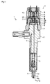
- Fig. 1 is a side view of an entire construction of an injector according to an embodiment of the present invention.
- Fig. 2 is a side view of a detailed construction of a group of injection holes according to an embodiment of the present invention.
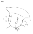
- Fig. 3 is a perspective view showing a conventional group of injection holes and boring portions of the group of injection holes.
- Fig. 4 is a perspective view showing a group of injection holes and boring portions of the group of injection holes (flat sections) according to the first embodiment.
- Fig. 5 is a perspective view showing a group of injection holes and boring portions of the group of injection holes (flat sections) according to the second embodiment. As shown in Fig.
- an injector 1 includes an injector body 2, a solenoid valve 3, a command piston body 5 and a nozzle body 7.
- the command piston body 5, which is provided on the lower portion of the injector body 2, is slidably provided therein with the command piston 4.
- the nozzle body 7, which is provided on the lower portion of the command piston body 5, is slidably provided therein with a needle valve 6. Due to the above construction, the injector 1 is set up to inject high-pressure fuels, which is supplied from a common-rail (not shown) to a fuel supplier 8, through injection holes 10a, 10a provided at the end portion of the nozzle body 7.
- an orifice plate 12 and a valve sheet 13 are integrated with the injector body 2 by a valve holding member 11, and a cap 15, in which a solenoid core 14 is disposed in the valve holding member 11, is fixed on the injector body 2.
- An axial valve disc 21 is vertically, slidably provided with the valve sheet 13.
- the valve disc 21 is constantly biased downwardly by an elastic force of a spring 16 internally provided in a spring chamber 14s of the solenoid core 14, and the valve disc sheet surface 21 a is attached to the valve sheet surface 13a of the valve sheet 13, so as to prevent a flowing out of the fuels from a high-pressure oil passage 13b to a low-pressure fuel chamber 18, thereby securing the back pressure of the command piston 4 through a controlling oil passage 9. Accordingly, the command piston 4 is moved downwardly by the back pressure and presses downwardly the needle valve 6, thereby limiting the fuel injection.
- An armature 22 is fixed on the upper side of the valve disc 21.
- the armature 22 is vertically, movably disposed in the low-pressure fuel chamber 18 formed between the solenoid core 14 and the valve sheet 13.
- a solenoid coil 17 When a solenoid coil 17 is energized, the armature 22 is moved upwardly with the valve disc 21, the valve disc sheet surface 21a is detached from the valve sheet surface 13a and the fuels in the high-pressure oil passage 13b are flowed out to the low-pressure fuel chamber 18. Accordingly, the high-pressure fuels in the controlling oil passage 9 are flowed out to the low-pressure fuel chamber 18, and the back pressure of the command piston 4 is decreased.
- the needle valve 6 is lifted by the high-pressure fuels supplied in the nozzle fuel chamber 6a, thereby injecting the fuels.
- the armature 22 is moved in the low-pressure fuel chamber 18 between the solenoid core 14 and the valve sheet 13, thereby limiting the flow of the fuels for the injection control by the valve disc 21 integral with the armature 22, so as to control the fuel injection.
- the entire construction of the injection as a major portion of the present invention was described.
- the injector 1 includes so-called a group of injection holes 10.
- the group of injection holes 10 is configured to form a plurality of injection holes 10a, 10a, having respective different axis lines to the axis direction, on a plane surface including an axis line of the nozzle body 7 (i.e., an axis line of the injector 1).
- the injection holes 10a, 10a are disposed so that a plurality of intersections (the intersections X and Y) between the axis line (the axis line A) of the nozzle body 7 and the axes (the axis lines B and C) of the injection holes 10a, 10a are present in the axis direction of the nozzle body 7.
- a plurality of intersections (the intersections X and Y) between the axis line (the axis line A) of the nozzle body 7 and the axes (the axis lines B and C) of the injection holes 10a, 10a are present in the axis direction of the nozzle body 7.
- the group of injection holes 10 on any cross section are shown, but a plurality of group of injection holes 10 are radially disposed at even intervals centered around the axis line of the nozzle body 7, as an entire construction of the nozzle body 7.
- the injection holes 10a are set up to communicate with a sack 43 but not limited to the construction. As mentioned above, the construction of the group of injection holes according to an embodiment of the present invention was described.
- the group of injection holes 10 are formed at the spherical end portion of the nozzle body 7.
- the injection holes 10a, 10a are bored by an inexpensive machining process (for example, a process by a drill), but a positioning of the end of the drill is difficult by a skidding or an escape of a blade edge of a machine tool, when the outer shape thereof is a curved surface, leading to a displacement of it, whereby it was difficult to secure dimensional tolerances of the injection holes 10a, 10a. Therefore, embodiments of the present invention capable of easily improving the processing accuracy will be described below.
- the group of injection holes 10 (the injection holes 10a, 10a) is provided at the boring portions thereof with recessed portions 10b, the recessed portions 10b are provided at the bottom thereof with flat sections 10c, and the flat sections 10c are provide with the group of injection holes 10.
- the flat sections 10c form planar surfaces perpendicular to the axis lines of the bored injection holes 10a and can be easily formed by the machining such as a cutting or a forging.
- the dimensional tolerance such as relative positions/angles of the respective recessed portions 10b, 10b..., or the respective flat sections 10c, 10c..., can be secured with comparative ease by the machining process.
- the processing accuracy can be improved by boring the injection holes 10a, 10a with a drilling hole processing, on the flat sections 10c where the dimensional tolerance has been secured.
- the group of injection holes 10 (the injection holes 10a, 10a) is bored with a drilling hole processing, on the respective flat sections 10c, 10c..., is provided without limitation, but the group of injection holes 10 can be bored by the electrical discharging.
- the group of injection holes 10 can be bored by the electrical discharging.
- a dispersion of spark energy can be reduced, thereby easily securing a high dimensional tolerance.
- the group of injection holes 10 (the injection holes 10a, 10a) is provided at the boring portions thereof with flat sections 10d, and the flat sections 10d are provided with the group of injection holes 10.
- the flat sections 10d form planar surfaces perpendicular to the axis lines of the bored injection holes 10a and can be easily formed by the machining such as the cutting or forging.
- the dimensional tolerance such as relative positions/angles of the respective flat sections 10d, 10d..., can be secured with comparative ease by the machining process.
- the processing accuracy can be improved by boring the injection holes 10a, 10a with a drilling hole processing on the flat sections 10d where the dimensional tolerance has been secured.
- the group of injection holes 10 (the injection holes 10a, 10a) is bored with the machining (e.g., the drilling hole processing), on the respective flat sections 10d, 10d..., is provided without limitation, but as is the case with the first embodiment, the group of injection holes 10 can be bored by the electrical discharging.
- the boring potions of the injection holes 10a are formed on the flat sections 10c, 10d, which are perpendicular to the injection holes 10a and include the apertures of the injection holes 10a. Accordingly, the processing tolerance of the injection holes can be decreased, and variations of the exhaust gas property can be reduced, thereby acquiring the stable performance.
- the boring portions are provided with the recessed portions 10b and the recessed portions 10b are provided at the bottom thereof with the flat sections 10c. Accordingly, the flat sections can be easily and accurately formed in the actual production processes.
- the flat sections 10c, 10d are formed by cutting the boring portions. Accordingly, the flat sections can be easily and accurately formed in the actual production processes.
- the flat sections 10c, 10d are formed by forging the boring portions. Accordingly, the flat sections can be easily and accurately formed in the actual production processes.
- the present invention can be widely available not only in the common-rail fuel injection device provided with the diesel engine but also in the fuel injection device where the injection holes for the fuel injection are formed.
Landscapes
- Engineering & Computer Science (AREA)
- Chemical & Material Sciences (AREA)
- Combustion & Propulsion (AREA)
- Mechanical Engineering (AREA)
- General Engineering & Computer Science (AREA)
- Manufacturing & Machinery (AREA)
- Fuel-Injection Apparatus (AREA)
- Nozzles (AREA)
- Perforating, Stamping-Out Or Severing By Means Other Than Cutting (AREA)
- Drilling And Boring (AREA)
Abstract
Description
- The present invention relates to a technique for an injector of an engine equipped with a common-rail fuel injection device, more specifically, a method for boring injection holes of fhe injector having so-called a group of injection holes.
- Conventionally, there is a well-known common-rail fuel injection device provided with a diesel engine. There is also a well-known concrete configuration of an injector injecting fuels supplied from the common-rail.
Moreover, an injector, which has a plurality of intersections between an axis line of the injector and the axes of injection holes bored in a nozzle body of the injector, i.e., which has a group of injection holes, is heretofore known. The injector having a group of injection holes can have smaller injection holes than an injector having the same amount of injection quantity without a group of injection holes. Therefore, it is noted that the injector having a group of injection holes enables injected fuels to be atomized and diffused over a wider range, compared to the injector without a group of injection holes, thereby improving an ignition performance and securing a low combustion noise and good combustion state, even when the engine is cool and low cetane value fuels are used. It is also known that the injector having a group of injection holes is effective as a means for cleaning up an exhaust gas, since it enables total hydrocarbons (THC) and particulate matters (PM) contained in the exhaust gas to be reduced. For example,JP 2006-70802 - However, it is proved from experimental results and the like that processing variations, such as boring positions of the injection holes, relative positions and angles or torsions to a circumferential direction of the respective injection holes, directly affect the exhaust gas property, in the injector having a group of injection holes.
So, the injector having a group of injection holes is required to inhibit the processing variations, such as boring positions of the injection holes, relative positions and angles or torsions to the circumferential direction of the respective injection holes, and to secure a high processing accuracy. Conventionally, as the injection holes are bored on curved surfaces of substantially spherical surfaces by electrical discharging, it is difficult to satisfy a predetermined figure tolerance and secure the processing accuracy in actual production processes, thereby reducing a distributive homogeneity of the injected fuels and causing variations of the exhaust gas property. Consequently, it was difficult to put the injector having a group of injection holes to practical use, due to the above-described problems.
Accordingly, in consideration to the above-discussed problems, it is an object of the present invention to provide a method for boring the injection holes of the injector having a group of injection holes, which is capable of securing the processing accuracy of the injection holes and reducing variations of the exhaust gas property, in actual production processes. - The problem so as to be solved by the present invention is as mentioned above. Next, the means of solving the problem will be described.
- In a method for boring injection holes of an injector according to the present invention, a method for boring injection holes of the injector having a plurality of intersections between an axis line of the injector and the axes of the injection holes bored in the injector, comprises a step of forming flat sections, which are perpendicular to the injection holes and include apertures of the injection holes, on the boring portions of the injection holes.
- In the method for boring injection holes of the injector according to the present invention, the boring portions are provided with recessed portions and the recessed portions are provided at the bottom thereof with the flat sections.
- In the method for boring injection holes of the injector according to the present invention, the flat sections are formed by cutting the boring portions.
- In the method for boring injection holes of the injector according to the present invention, the flat sections are formed by forging the boring portions.
- The present invention shows the following effects.
- In the method for boring injection holes of the injector according to the present invention, a method for boring injection holes of the injector having a plurality of intersections between an axis line of the injector and the axes of the injection holes bored in the injector comprises the step of forming a flat section, which are perpendicular to the injection holes and include apertures of the injection holes in boring portions of the injection holes, thereby decreasing a processing tolerance of the injection holes and reducing variations of the exhaust gas property so as to acquire a stable performance.
- In the method for boring injection holes of the injector according to the present invention, recessed portions are formed at the boring portions and the flat sections are formed at the bottom of the recessed portions, thereby easily and accurately forming the flat sections in the actual production processes.
- In the method for boring injection holes of the injector according to the present invention, the flat sections are formed by cutting the boring portions, thereby easily and accurately forming the flat sections in the actual production processes.
- In the method for boring injection holes of the injector according to the present invention, the flat sections are formed by forging the boring portions, thereby easily and accurately forming the flat sections in the actual production processes.
-
-
Fig. 1 is a side view of an entire construction of an injector according to an embodiment of the present invention. -
Fig. 2 is a side view of a detailed construction of a group of injection holes according to an embodiment of the present invention. -
Fig. 3 is a perspective view showing a conventional group of injection holes and boring portions of the group of injection holes. -
Fig. 4 is a perspective view showing a group of injection holes and boring portions of the group of injection holes (flat sections) according to the first embodiment. -
Fig. 5 is a perspective view showing a group of injection holes and boring portions of the group of injection holes (flat sections) according to the second embodiment. -
- 1 injector
- 10 a group of injection holes
- 10a injection hole
- 10b recessed portion
- 10c flat section
- 10d flat section
- Next, embodiments of the present invention will be described.
Fig. 1 is a side view of an entire construction of an injector according to an embodiment of the present invention.Fig. 2 is a side view of a detailed construction of a group of injection holes according to an embodiment of the present invention.Fig. 3 is a perspective view showing a conventional group of injection holes and boring portions of the group of injection holes.Fig. 4 is a perspective view showing a group of injection holes and boring portions of the group of injection holes (flat sections) according to the first embodiment.Fig. 5 is a perspective view showing a group of injection holes and boring portions of the group of injection holes (flat sections) according to the second embodiment.
As shown inFig. 1 , aninjector 1 includes an injector body 2, a solenoid valve 3, a command piston body 5 and anozzle body 7. The solenoid valve 3, which is provided on the upper portion of the injector body 2, controls a back pressure of a command piston 4 so as to control a fuel injection. The command piston body 5, which is provided on the lower portion of the injector body 2, is slidably provided therein with the command piston 4. Thenozzle body 7, which is provided on the lower portion of the command piston body 5, is slidably provided therein with aneedle valve 6. Due to the above construction, theinjector 1 is set up to inject high-pressure fuels, which is supplied from a common-rail (not shown) to afuel supplier 8, throughinjection holes nozzle body 7. - As shown
Figs. 1 and2 , in the solenoid valve 3, anorifice plate 12 and avalve sheet 13 are integrated with the injector body 2 by avalve holding member 11, and acap 15, in which asolenoid core 14 is disposed in thevalve holding member 11, is fixed on the injector body 2. Anaxial valve disc 21 is vertically, slidably provided with thevalve sheet 13. Thevalve disc 21 is constantly biased downwardly by an elastic force of aspring 16 internally provided in a spring chamber 14s of thesolenoid core 14, and the valve disc sheet surface 21 a is attached to thevalve sheet surface 13a of thevalve sheet 13, so as to prevent a flowing out of the fuels from a high-pressure oil passage 13b to a low-pressure fuel chamber 18, thereby securing the back pressure of the command piston 4 through a controllingoil passage 9. Accordingly, the command piston 4 is moved downwardly by the back pressure and presses downwardly theneedle valve 6, thereby limiting the fuel injection. - An
armature 22 is fixed on the upper side of thevalve disc 21.
Thearmature 22 is vertically, movably disposed in the low-pressure fuel chamber 18 formed between thesolenoid core 14 and thevalve sheet 13.
When asolenoid coil 17 is energized, thearmature 22 is moved upwardly with thevalve disc 21, the valve disc sheet surface 21a is detached from thevalve sheet surface 13a and the fuels in the high-pressure oil passage 13b are flowed out to the low-pressure fuel chamber 18. Accordingly, the high-pressure fuels in the controllingoil passage 9 are flowed out to the low-pressure fuel chamber 18, and the back pressure of the command piston 4 is decreased. Then, theneedle valve 6 is lifted by the high-pressure fuels supplied in thenozzle fuel chamber 6a, thereby injecting the fuels.
As described above, thearmature 22 is moved in the low-pressure fuel chamber 18 between thesolenoid core 14 and thevalve sheet 13, thereby limiting the flow of the fuels for the injection control by thevalve disc 21 integral with thearmature 22, so as to control the fuel injection.
As mentioned above, the entire construction of the injection as a major portion of the present invention was described. - Next, a construction of a group of injection holes according to an embodiment of the present invention will be described with reference to
Fig. 2 . As shown inFig. 2 , theinjector 1 according to an embodiment of the present invention includes so-called a group ofinjection holes 10.
The group ofinjection holes 10 is configured to form a plurality ofinjection holes
In other words, theinjection holes nozzle body 7 and the axes (the axis lines B and C) of theinjection holes nozzle body 7.
Incidentally, in the present embodiment, an example, in which two points of intersections between the axis line of thenozzle body 7 and the axes of theinjection holes
InFig. 2 , the group of injection holes 10 on any cross section are shown, but a plurality of group of injection holes 10 are radially disposed at even intervals centered around the axis line of thenozzle body 7, as an entire construction of thenozzle body 7.
Incidentally, in the present invention, theinjection holes 10a are set up to communicate with asack 43 but not limited to the construction.
As mentioned above, the construction of the group of injection holes according to an embodiment of the present invention was described. - Next, flat sections formed at boring portions of a group of injection holes, according to an embodiment of the present invention, will be described with reference to
Figs. 3 to 5 .
As shown inFig. 3 , in the injector having a conventional group of injection holes, the group of injection holes 10 are formed at the spherical end portion of thenozzle body 7.
The injection holes 10a, 10a are bored by an inexpensive machining process (for example, a process by a drill), but a positioning of the end of the drill is difficult by a skidding or an escape of a blade edge of a machine tool, when the outer shape thereof is a curved surface, leading to a displacement of it, whereby it was difficult to secure dimensional tolerances of theinjection holes
Therefore, embodiments of the present invention capable of easily improving the processing accuracy will be described below. - As shown in
Fig. 4 , the group of injection holes 10 (theinjection holes portions 10b, the recessedportions 10b are provided at the bottom thereof withflat sections 10c, and theflat sections 10c are provide with the group of injection holes 10. - The
flat sections 10c form planar surfaces perpendicular to the axis lines of thebored injection holes 10a and can be easily formed by the machining such as a cutting or a forging. The dimensional tolerance, such as relative positions/angles of the respective recessedportions flat sections
Thus, the processing accuracy can be improved by boring theinjection holes flat sections 10c where the dimensional tolerance has been secured. - Incidentally, in the present embodiment, an example, in which the group of injection holes 10 (the
injection holes flat sections flat sections 10c, a dispersion of spark energy can be reduced, thereby easily securing a high dimensional tolerance. - As shown in
Fig. 5 , the group of injection holes 10 (theinjection holes flat sections 10d, and theflat sections 10d are provided with the group of injection holes 10. - The
flat sections 10d form planar surfaces perpendicular to the axis lines of thebored injection holes 10a and can be easily formed by the machining such as the cutting or forging. The dimensional tolerance, such as relative positions/angles of the respectiveflat sections
Thus, the processing accuracy can be improved by boring theinjection holes flat sections 10d where the dimensional tolerance has been secured. - Incidental ly, in the present embodiment, an example, in which the group of injection holes 10 (the
injection holes flat sections - In the present embodiment, an example of processing by the cutting and forging is shown as a machining method of the
flat sections
As mentioned above, the flat sections formed on the boring portions of the group of injection holes according to an embodiment of the present invention was described. - According to the foregoing explanation, in the method for boring the injection holes of the
injector 1 having a plurality of intersections between the axis line of theinjector 1 and the axes of the injection holes 10a bored in theinjector 1, or so-called a group of injection holes, the boring potions of theinjection holes 10a are formed on theflat sections injection holes 10a.
Accordingly, the processing tolerance of the injection holes can be decreased, and variations of the exhaust gas property can be reduced, thereby acquiring the stable performance. - The boring portions are provided with the recessed
portions 10b and the recessedportions 10b are provided at the bottom thereof with theflat sections 10c. Accordingly, the flat sections can be easily and accurately formed in the actual production processes. - The
flat sections - The
flat sections - The present invention can be widely available not only in the common-rail fuel injection device provided with the diesel engine but also in the fuel injection device where the injection holes for the fuel injection are formed.
Claims (4)
- A method for boring injection holes of an injector having a plurality of intersections between an axis line of an injector and the axes of the injection holes bored in the injector, comprising a step of:forming flat sections, which are perpendicular to the injection holes and include apertures of the injection holes, on the boring portions of the injection holes.
- The method for boring injection holes of the injector as set forth in claim 1, wherein the boring portions are provided with recessed portions and the recessed portions are provided at the bottom thereof with the flat sections.
- The method for boring injection holes of the injector as set forth in any one of claims 1 or 2, wherein the flat sections are formed by cutting the boring portions.
- The method for boring injection holes of the injector as set forth in any one of claims 1 or 2, wherein the flat sections are formed by forging the boring portions.
Applications Claiming Priority (2)
| Application Number | Priority Date | Filing Date | Title |
|---|---|---|---|
| JP2006202573A JP2008025552A (en) | 2006-07-25 | 2006-07-25 | Nozzle hole boring method of injector |
| PCT/JP2007/061385 WO2008012993A1 (en) | 2006-07-25 | 2007-06-05 | Method of forming injection hole for injector |
Publications (2)
| Publication Number | Publication Date |
|---|---|
| EP2048354A1 true EP2048354A1 (en) | 2009-04-15 |
| EP2048354A4 EP2048354A4 (en) | 2011-09-28 |
Family
ID=38981308
Family Applications (1)
| Application Number | Title | Priority Date | Filing Date |
|---|---|---|---|
| EP07744737A Withdrawn EP2048354A4 (en) | 2006-07-25 | 2007-06-05 | Method of forming injection hole for injector |
Country Status (8)
| Country | Link |
|---|---|
| US (1) | US20090320284A1 (en) |
| EP (1) | EP2048354A4 (en) |
| JP (1) | JP2008025552A (en) |
| CN (1) | CN101501325A (en) |
| BR (1) | BRPI0714595A2 (en) |
| CA (1) | CA2658933C (en) |
| RU (1) | RU2415295C2 (en) |
| WO (1) | WO2008012993A1 (en) |
Cited By (2)
| Publication number | Priority date | Publication date | Assignee | Title |
|---|---|---|---|---|
| WO2010121767A1 (en) * | 2009-04-20 | 2010-10-28 | Prelatec Gmbh | Nozzle having at least one spray hole for vaporizing fluids |
| US8237083B2 (en) | 2007-10-25 | 2012-08-07 | Prelatec Gmbh | Method for boring bottle-like holes having a defined geometry by means of pulsed laser radiation |
Families Citing this family (2)
| Publication number | Priority date | Publication date | Assignee | Title |
|---|---|---|---|---|
| DE102013220917A1 (en) * | 2013-10-15 | 2015-04-16 | Continental Automotive Gmbh | injection |
| RU2726449C1 (en) * | 2019-12-30 | 2020-07-14 | Федеральное государственное автономное образовательное учреждение высшего образования "Южно-Уральский государственный университет (национальный исследовательский университет)" ФГАОУ ВО "ЮУрГУ (НИУ)" | Sprayer for diesel injector |
Family Cites Families (13)
| Publication number | Priority date | Publication date | Assignee | Title |
|---|---|---|---|---|
| GB575600A (en) * | 1943-02-17 | 1946-02-25 | Sulzer Ag | Improvements in or relating to fuel injection valves for internal combustion engines |
| GB1210381A (en) * | 1967-01-13 | 1970-10-28 | Bryce Berger Ltd | Liquid fuel injection nozzle units for internal combustion engines |
| DE2710138A1 (en) * | 1977-03-09 | 1978-09-14 | Maschf Augsburg Nuernberg Ag | MULTI-HOLE INJECTION NOZZLE |
| SU879001A1 (en) * | 1980-01-03 | 1981-11-07 | Центральный Научно-Исследовательский И Конструкторский Институт Топливной Аппаратуры Автотракторных И Стационарных Двигателей | Diesel engine injection nozzle sprayer body |
| JPS5987271A (en) * | 1982-11-09 | 1984-05-19 | Yanmar Diesel Engine Co Ltd | Fuel injection valve for diesel engine |
| SU1165812A1 (en) * | 1983-06-30 | 1985-07-07 | Ярославский завод дизельной аппаратуры | Method of stabilizing dimensions of nozzle holes of diesel engine injector atomizer |
| FR2663084B1 (en) * | 1990-06-07 | 1992-07-31 | Semt Pielstick | INJECTION DEVICE FOR AN INTERNAL COMBUSTION ENGINE. |
| JPH11117833A (en) * | 1997-10-13 | 1999-04-27 | Honda Motor Co Ltd | Fuel injection nozzle and method of manufacturing the same |
| US6199539B1 (en) * | 2000-06-22 | 2001-03-13 | Detroit Diesel Corporation | Anti-rotation mechanism for a high pressure fuel supply pipe in a common rail fuel system |
| DE10255375A1 (en) * | 2002-11-27 | 2004-06-24 | Siemens Ag | Injector for injecting fuel |
| DE10309058A1 (en) * | 2003-03-01 | 2004-09-09 | Robert Bosch Gmbh | Fuel injection valve for internal combustion engine has one or more pins for securing housing parts in relative positions rotated by angle relative to central axis of fuel injection valve |
| JP2005299642A (en) * | 2004-03-17 | 2005-10-27 | Denso Corp | Fuel injection nozzle |
| JP4155251B2 (en) * | 2004-09-02 | 2008-09-24 | 株式会社デンソー | Fuel injection nozzle |
-
2006
- 2006-07-25 JP JP2006202573A patent/JP2008025552A/en active Pending
-
2007
- 2007-06-05 RU RU2009106460/06A patent/RU2415295C2/en not_active IP Right Cessation
- 2007-06-05 CN CNA2007800278246A patent/CN101501325A/en active Pending
- 2007-06-05 BR BRPI0714595-0A patent/BRPI0714595A2/en not_active IP Right Cessation
- 2007-06-05 US US12/374,907 patent/US20090320284A1/en not_active Abandoned
- 2007-06-05 WO PCT/JP2007/061385 patent/WO2008012993A1/en not_active Ceased
- 2007-06-05 CA CA2658933A patent/CA2658933C/en not_active Expired - Fee Related
- 2007-06-05 EP EP07744737A patent/EP2048354A4/en not_active Withdrawn
Cited By (2)
| Publication number | Priority date | Publication date | Assignee | Title |
|---|---|---|---|---|
| US8237083B2 (en) | 2007-10-25 | 2012-08-07 | Prelatec Gmbh | Method for boring bottle-like holes having a defined geometry by means of pulsed laser radiation |
| WO2010121767A1 (en) * | 2009-04-20 | 2010-10-28 | Prelatec Gmbh | Nozzle having at least one spray hole for vaporizing fluids |
Also Published As
| Publication number | Publication date |
|---|---|
| EP2048354A4 (en) | 2011-09-28 |
| BRPI0714595A2 (en) | 2013-02-19 |
| RU2415295C2 (en) | 2011-03-27 |
| CN101501325A (en) | 2009-08-05 |
| US20090320284A1 (en) | 2009-12-31 |
| CA2658933A1 (en) | 2008-01-31 |
| WO2008012993A1 (en) | 2008-01-31 |
| CA2658933C (en) | 2011-09-13 |
| JP2008025552A (en) | 2008-02-07 |
| RU2009106460A (en) | 2010-08-27 |
Similar Documents
| Publication | Publication Date | Title |
|---|---|---|
| EP2302197B1 (en) | Fuel injection valve and fuel injection device | |
| USRE37633E1 (en) | Accumulating fuel injection apparatus | |
| US8672239B2 (en) | Fuel injector | |
| US7571891B2 (en) | Solenoid valve | |
| US8087598B2 (en) | Nozzle module for an injection valve | |
| US20110180634A1 (en) | Nozzle body, nozzle assembly and fuel injector, and method for producing a nozzle body | |
| EP1150001B1 (en) | Solenoid valve and fuel injector using same | |
| EP2048354A1 (en) | Method of forming injection hole for injector | |
| US6945478B2 (en) | Fuel injector having an orifice plate with offset coining angled orifices | |
| US8567063B2 (en) | Method of machining orifice and press-working method | |
| US20130062441A1 (en) | Fuel Injector | |
| EP2937553B1 (en) | Vehicular high pressure direct injection type injector with valve seat body for fuel-atomization | |
| CN108518293A (en) | The method for manufacturing the method for injector and at least two injectors being made to coordinate | |
| JP2008291722A (en) | Fuel injection valve | |
| US20030141476A1 (en) | Connection between an armature and a valve needle of a fuel injection valve | |
| US10364785B2 (en) | Fuel injection nozzle | |
| CN102213171A (en) | Fuel injector with variable area pintle nozzle | |
| CN1798920A (en) | Fuel injection valve | |
| CN102086827B (en) | Fluid injector with thermal load control | |
| US20200271078A1 (en) | Fuel injector | |
| US20190113012A1 (en) | Valve for metering a fluid, especially a fuel injector | |
| EP1794442B1 (en) | Fuel injector with vop loss resistant valve spring for emissions-compliant engine applications i | |
| KR20010079756A (en) | Injection nozzle with blind bore for internal combustion engine with rounded passage between the blind bore and the injector needle seat | |
| EP1481160B1 (en) | Fuel injection system | |
| WO2009092690A1 (en) | Injection nozzle |
Legal Events
| Date | Code | Title | Description |
|---|---|---|---|
| PUAI | Public reference made under article 153(3) epc to a published international application that has entered the european phase |
Free format text: ORIGINAL CODE: 0009012 |
|
| 17P | Request for examination filed |
Effective date: 20090225 |
|
| AK | Designated contracting states |
Kind code of ref document: A1 Designated state(s): AT BE BG CH CY CZ DE DK EE ES FI FR GB GR HU IE IS IT LI LT LU LV MC MT NL PL PT RO SE SI SK TR |
|
| AX | Request for extension of the european patent |
Extension state: AL BA HR MK RS |
|
| DAX | Request for extension of the european patent (deleted) | ||
| RBV | Designated contracting states (corrected) |
Designated state(s): DE FR GB IT NL SE |
|
| RIN1 | Information on inventor provided before grant (corrected) |
Inventor name: TSUDA, TOMOYUKI Inventor name: SHINOHARA, YUKIHIRO Inventor name: KAWABE, TAKAO Inventor name: SHIMIZU, KOUJI Inventor name: ASAI, GOU Inventor name: UKAI, SATOMI Inventor name: TAKAHATA, TERUMITSU Inventor name: TAKAHASHI, TAKESHI |
|
| A4 | Supplementary search report drawn up and despatched |
Effective date: 20110831 |
|
| RIC1 | Information provided on ipc code assigned before grant |
Ipc: F02M 61/18 20060101AFI20110825BHEP |
|
| 17Q | First examination report despatched |
Effective date: 20120306 |
|
| STAA | Information on the status of an ep patent application or granted ep patent |
Free format text: STATUS: THE APPLICATION IS DEEMED TO BE WITHDRAWN |
|
| 18D | Application deemed to be withdrawn |
Effective date: 20120717 |