EP2047808A2 - Orthopädische Zielvorrichtung mit einstellbarem Winkel - Google Patents
Orthopädische Zielvorrichtung mit einstellbarem Winkel Download PDFInfo
- Publication number
- EP2047808A2 EP2047808A2 EP08017737A EP08017737A EP2047808A2 EP 2047808 A2 EP2047808 A2 EP 2047808A2 EP 08017737 A EP08017737 A EP 08017737A EP 08017737 A EP08017737 A EP 08017737A EP 2047808 A2 EP2047808 A2 EP 2047808A2
- Authority
- EP
- European Patent Office
- Prior art keywords
- targeting
- orthopedic device
- adjustment member
- bore
- intramedullary implant
- Prior art date
- Legal status (The legal status is an assumption and is not a legal conclusion. Google has not performed a legal analysis and makes no representation as to the accuracy of the status listed.)
- Granted
Links
- 230000008685 targeting Effects 0.000 title claims abstract description 62
- 230000000399 orthopedic effect Effects 0.000 title claims abstract description 37
- 239000007943 implant Substances 0.000 claims abstract description 35
- 230000008859 change Effects 0.000 claims abstract description 8
- 210000003423 ankle Anatomy 0.000 description 8
- 208000037873 arthrodesis Diseases 0.000 description 5
- 210000000988 bone and bone Anatomy 0.000 description 4
- 230000009977 dual effect Effects 0.000 description 4
- 230000001054 cortical effect Effects 0.000 description 2
- 230000007613 environmental effect Effects 0.000 description 2
- 238000000034 method Methods 0.000 description 2
- 230000004048 modification Effects 0.000 description 2
- 238000012986 modification Methods 0.000 description 2
- 230000006641 stabilisation Effects 0.000 description 2
- 238000011105 stabilization Methods 0.000 description 2
- 210000000549 articulatio subtalaris Anatomy 0.000 description 1
- 230000008901 benefit Effects 0.000 description 1
- 238000005553 drilling Methods 0.000 description 1
- 239000000463 material Substances 0.000 description 1
- 210000004872 soft tissue Anatomy 0.000 description 1
- 238000010408 sweeping Methods 0.000 description 1
Images



Classifications
-
- A—HUMAN NECESSITIES
- A61—MEDICAL OR VETERINARY SCIENCE; HYGIENE
- A61B—DIAGNOSIS; SURGERY; IDENTIFICATION
- A61B17/00—Surgical instruments, devices or methods
- A61B17/16—Instruments for performing osteoclasis; Drills or chisels for bones; Trepans
- A61B17/17—Guides or aligning means for drills, mills, pins or wires
-
- A—HUMAN NECESSITIES
- A61—MEDICAL OR VETERINARY SCIENCE; HYGIENE
- A61B—DIAGNOSIS; SURGERY; IDENTIFICATION
- A61B17/00—Surgical instruments, devices or methods
- A61B17/16—Instruments for performing osteoclasis; Drills or chisels for bones; Trepans
- A61B17/17—Guides or aligning means for drills, mills, pins or wires
- A61B17/1725—Guides or aligning means for drills, mills, pins or wires for applying transverse screws or pins through intramedullary nails or pins
-
- A—HUMAN NECESSITIES
- A61—MEDICAL OR VETERINARY SCIENCE; HYGIENE
- A61B—DIAGNOSIS; SURGERY; IDENTIFICATION
- A61B17/00—Surgical instruments, devices or methods
- A61B17/16—Instruments for performing osteoclasis; Drills or chisels for bones; Trepans
- A61B17/17—Guides or aligning means for drills, mills, pins or wires
- A61B17/1735—Guides or aligning means for drills, mills, pins or wires for rasps or chisels
-
- A—HUMAN NECESSITIES
- A61—MEDICAL OR VETERINARY SCIENCE; HYGIENE
- A61B—DIAGNOSIS; SURGERY; IDENTIFICATION
- A61B17/00—Surgical instruments, devices or methods
- A61B17/16—Instruments for performing osteoclasis; Drills or chisels for bones; Trepans
- A61B17/17—Guides or aligning means for drills, mills, pins or wires
- A61B17/1739—Guides or aligning means for drills, mills, pins or wires specially adapted for particular parts of the body
- A61B17/1775—Guides or aligning means for drills, mills, pins or wires specially adapted for particular parts of the body for the foot or ankle
Definitions
- the present teachings provide a device that allows variable angle targeting for bone fasteners and can be used with various targeting systems.
- the present teachings provide an orthopedic device for use with a targeting system for intramedullary fixation.
- the orthopedic device can provide a variable angle orientation for guiding members of the targeting system.
- the orthopedic device can provide variable angular orientation in more than one sagittal plane relative to an intramedullary implant.
- the present teachings provide an orthopedic device that includes a targeting member, an elongated guiding member, and an adjustment member.
- the targeting member has an elongated body along a first longitudinal axis and can be coupled to an intramedullary implant such that the first longitudinal axis is parallel to the intramedullary implant.
- the targeting member includes a first bore extending along a second longitudinal axis through the elongated body, the first bore having a cross-section elongated in the direction of the first longitudinal axis.
- the first and second longitudinal axes define a first plane.
- the elongated guiding member passes through the first bore and is movable relative to the first longitudinal axis.
- the adjustment member is coupled to the elongated body and operates to change an orientation of the guiding member relative to the first longitudinal axis in the first plane.
- the present teachings provide an orthopedic device that includes a targeting member couplable to an intramedullary implant, the targeting member including a body defining a first bore having an elongated cross-section and a second bore transversely intersecting the first bore.
- the orthopedic device also includes a guiding member passing through the first bore, the guiding member movable in a first plane parallel to the intramedullary implant and not intersecting the intramedullary implant.
- An adjustment member is pivotably coupled to the body and has a shaft received in the second bore of the targeting member.
- the shaft has a third bore transverse to the shaft, the third bore receiving the guiding member, such that rotation of the adjustment member changes the orientation of the guiding member relative to the intramedullary implant in the first plane.
- the present teachings also provide an orthopedic device that includes an intramedullary implant, a targeting member coupled to the intramedullary implant, the targeting member including a body having first and second bores having elongated cross-sections, and first and second guiding members passing through the corresponding first and second bores.
- the first and second guiding members can move in first and second planes parallel to the intramedullary implant and not intersecting the intramedullary implant.
- the orthopedic device also includes a first adjustment member coupled to the targeting member, the first adjustment member pivotable along a first curved slot relative to the targeting member, such that rotation of the first adjustment member changes an orientation of the first guiding member relative to the intramedullary implant in the first plane.
- the orthopedic device also includes a second adjustment member coupled to the targeting member, the second adjustment member pivotable along a second curved slot relative to the targeting member, such that rotation of the second adjustment member changes an orientation of the second guiding member relative to the intramedullary implant in the second plane. Further, the orthopedic device includes a first locking member coupled to the first adjustment member and to the targeting member for locking the orientation of the first guiding member, and a second locking member coupled to the second adjustment member and to the targeting member for locking the orientation of the second guiding member.
- FIG. 1 is an isometric view of a variable angle targeting device according to the present teachings
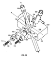
- FIG. 1A is a partially exploded view of the device of FIG. 1 ;
- FIG. 2 is a top view of the device of FIG. 1 ;
- FIG. 3 is a front view of the device of FIG. 1 ;
- FIG. 4 is a side view of the device of FIG. 1 ;
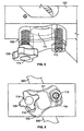
- FIG. 5 is a top and side isometric view detail of FIG. 1 ;
- FIG. 6 is a front view detail of FIG. 1 ;
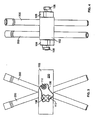
- FIG. 7 is an environmental isometric view of the device of FIG. 1 , shown in the environment of a targeting system for ankle arthrodesis;
- FIG. 8 an environmental front view of the device of FIG. 1 , shown in the environment of a targeting system for ankle arthrodesis.
- an exemplary variable angle targeting device 100 can include a rotatable adjustment member 106, a locking member 108, a locking shaft 114 that can be threadably engaged with the locking member 108, and a spring-loaded plunger 110 coupled to a supporting body 102.
- the body 102 can have first and second opposing surfaces 220 and 222, and third and fourth opposing surfaces 224, 226.
- the variable angle targeting device 100 can be coupled to one or both of the first and second surfaces 220, 222 of the body 102 with a corresponding adjustment member 106, a locking member 108, and a spring-loaded plunger 110.
- the variable angle targeting device 100 can also include one or more tubular guiding members 200, which can be soft tissue sleeves, drilling guide sleeves or other aiming devices.
- the body 102 can be a portion of an orthopedic targeting/aiming system, such as an integral portion of a targeting member 210 shown in FIGS. 7 and 8 , or a separate support component. Accordingly, the variable angle targeting device 100 can be positioned on one of or on both the lateral and medial sides of the targeting member 210, corresponding to the first and second surfaces 220, 222 of the body 102. Such dual positioning of the variable angle targeting device 100 can provide the surgeon with greater flexibility.
- variable angle targeting device 100 In the ankle arthrodesis procedure illustrated in FIGS. 7 and 8 , for example, the surgeon can place cortical screws to fuse the ankle and the subtalar joints independently.
- dual positioning of the variable angle targeting device 100 is illustrated throughout FIGS. 1-8 , it will be appreciated that single positioning on one of the first or second surfaces 220, 222 can also be used. In the sequel, only one set of the various parts of the variable angle targeting device 100 is described, with the understanding that a second set, which can be used for dual positioning, is similar. For orientation purposes in relation to the targeting system of FIG.
- the surfaces 220, 222, 224, 226 are referenced as lateral surface 220, medial surface 222, anterior surface 224 and posterior surface 226, and the variable angle targeting device 100 is described in reference to the lateral position shown in FIG. 7 .
- the body 102 can have an elongated through-slot 104, through which the guiding member 200 can pass from the posterior surface 226 to the anterior surface 224 of the body 102.
- the elongated slot 104 can have a cross-section elongated along an axial direction A.
- the body 102 can also have a side or lateral opening 110 communicating transversely with the elongated slot 104.
- the adjustment member 106 can include a shaft portion 105 having a transverse hole 103. The shaft portion 105 can be inserted through the side opening 111 of the body 102 and can be rotatably coupled to the body, such that the guiding member 200 can pass through the transverse hole 103.
- Rotating the adjustment member 106 which can be knob-like for manual rotation, can change the orientation of the guiding member 200 relative to the axial direction A, such that an angle ⁇ defined between the axial axis A and a longitudinal axis B of the guiding member 200 can be selectively changed.
- the adjustment member 106 can include a curved slot 112.
- the locking shaft 114 can include a threaded portion 130 and an unthreaded portion 132.
- the locking shaft 114 can pass through the locking member 108 and through the curved slot 112 of the adjustment member 106, and can be inserted into a hole 119 of the body 102.
- the adjustment member 108 With the locking member 108 not tightened, the adjustment member 108 can swing relative to the locking shaft 112 along the curved slot 112.
- the locking member 108 can be threadably tightened in the locking shaft 114, until it presses the adjustment member 108 against the body 102 to prevent further movement of the adjustment member 106 and secure the orientation of the guiding member 200 at a selected angle.
- the adjustment member 106 can include an opening 107 threadably receiving a spring-loaded ball plunger 110.
- the ball plunger 110 can interact with a series of detents 116 defined along a curve on the lateral surface 220 of the body 102.
- the detents 116 can be equally spaced and configured to provide graduated increments indicating to the user the degree of angular adjustment or change of the guiding member 200.
- the plunger 110 interfaces with the detents 116 producing an audible and tactile feedback to the user.
- the extent of the slot 112 can provide upper and lower limits for the degree of adjustment available.
- variable angle device 100 can be used with various targeting systems to provide angular adjustability for guiding members 200 to allow the placement of various stabilization screws, cortical screws, transverse screws and other bone fasteners 212 at a desired orientation in a sagittal plane.
- the targeting system can include for example, a connecting shaft 216 that can be attached to an internal fixation implant 214, such an intramedullary nail or other fixation implant
- the targeting member 210 can be rotatably coupled to the connecting shaft 216 sweeping a transverse plane that is substantially perpendicular to the intramedullary nail 214 and to the axial axis A of the targeting member 210.
- variable angle device 100 can provide additional angular adjustability by allowing angulation on a sagittal plane defined by axes A and B. Additionally, using dual positioning and placing variable angle devices 100 on both the lateral surface 220 and the medial surface 222 of the targeting member 210, two guiding members 200 can be angulated independently of one another, thereby allowing independent fixation of bone fasteners in two different positions, for ankle and talar joints, for example, when used with an ankle targeting system for ankle arthrodesis. Further, the variable angle device 100 can provide variable sagittal alignment for stabilization screws 212 that do not pass through the intramedullary nail 214, but are positioned laterally and medially outside the intramedullary nail 214.
Landscapes
- Health & Medical Sciences (AREA)
- Surgery (AREA)
- Life Sciences & Earth Sciences (AREA)
- Biomedical Technology (AREA)
- Medical Informatics (AREA)
- Orthopedic Medicine & Surgery (AREA)
- Oral & Maxillofacial Surgery (AREA)
- Engineering & Computer Science (AREA)
- Dentistry (AREA)
- Heart & Thoracic Surgery (AREA)
- Nuclear Medicine, Radiotherapy & Molecular Imaging (AREA)
- Molecular Biology (AREA)
- Animal Behavior & Ethology (AREA)
- General Health & Medical Sciences (AREA)
- Public Health (AREA)
- Veterinary Medicine (AREA)
- Surgical Instruments (AREA)
- Prostheses (AREA)
Applications Claiming Priority (2)
| Application Number | Priority Date | Filing Date | Title |
|---|---|---|---|
| US97881707P | 2007-10-10 | 2007-10-10 | |
| US12/244,433 US8187281B2 (en) | 2007-10-10 | 2008-10-02 | Variable angle targeting device |
Publications (3)
| Publication Number | Publication Date |
|---|---|
| EP2047808A2 true EP2047808A2 (de) | 2009-04-15 |
| EP2047808A3 EP2047808A3 (de) | 2010-05-19 |
| EP2047808B1 EP2047808B1 (de) | 2016-04-13 |
Family
ID=40225414
Family Applications (1)
| Application Number | Title | Priority Date | Filing Date |
|---|---|---|---|
| EP08017737.1A Not-in-force EP2047808B1 (de) | 2007-10-10 | 2008-10-09 | Orthopädische Zielvorrichtung mit einstellbarem Winkel |
Country Status (2)
| Country | Link |
|---|---|
| US (1) | US8187281B2 (de) |
| EP (1) | EP2047808B1 (de) |
Cited By (4)
| Publication number | Priority date | Publication date | Assignee | Title |
|---|---|---|---|---|
| WO2010122034A1 (en) * | 2009-04-21 | 2010-10-28 | Tornier | Foot positioning system and method |
| WO2011072249A1 (en) * | 2009-12-11 | 2011-06-16 | Small Bone Innovations, Inc. | Ankle fusion device, instrumentation and methods |
| CN103800049A (zh) * | 2012-11-14 | 2014-05-21 | 比德尔曼技术有限责任两合公司 | 用于引导钻机装置的靶向装置 |
| WO2018202786A3 (en) * | 2017-05-04 | 2018-12-20 | Orthofix S.R.L. | Improved bone screw for the treatment of bone collapses or deformations, such as in the case of the charcot foot, and insertion instrument of anti-migration elements into the bone screw |
Families Citing this family (36)
| Publication number | Priority date | Publication date | Assignee | Title |
|---|---|---|---|---|
| EP2224861B1 (de) * | 2007-10-17 | 2014-06-25 | ARO Medical ApS | Systeme und geräte zur torsionsstabilisierung |
| US20110125153A1 (en) * | 2008-06-24 | 2011-05-26 | Jeff Tyber | Intramedullary fixation assembly and method of use |
| US9017329B2 (en) * | 2008-06-24 | 2015-04-28 | Extremity Medical, Llc | Intramedullary fixation assembly and method of use |
| US8303589B2 (en) | 2008-06-24 | 2012-11-06 | Extremity Medical Llc | Fixation system, an intramedullary fixation assembly and method of use |
| US8343199B2 (en) * | 2008-06-24 | 2013-01-01 | Extremity Medical, Llc | Intramedullary fixation screw, a fixation system, and method of fixation of the subtalar joint |
| US9044282B2 (en) | 2008-06-24 | 2015-06-02 | Extremity Medical Llc | Intraosseous intramedullary fixation assembly and method of use |
| US9289220B2 (en) | 2008-06-24 | 2016-03-22 | Extremity Medical Llc | Intramedullary fixation assembly and method of use |
| US20110230884A1 (en) * | 2008-06-24 | 2011-09-22 | Adam Mantzaris | Hybrid intramedullary fixation assembly and method of use |
| US8313487B2 (en) * | 2008-06-24 | 2012-11-20 | Extremity Medical Llc | Fixation system, an intramedullary fixation assembly and method of use |
| US8328806B2 (en) | 2008-06-24 | 2012-12-11 | Extremity Medical, Llc | Fixation system, an intramedullary fixation assembly and method of use |
| US8414584B2 (en) | 2008-07-09 | 2013-04-09 | Icon Orthopaedic Concepts, Llc | Ankle arthrodesis nail and outrigger assembly |
| US8328807B2 (en) | 2008-07-09 | 2012-12-11 | Icon Orthopaedic Concepts, Llc | Ankle arthrodesis nail and outrigger assembly |
| WO2010054363A1 (en) * | 2008-11-10 | 2010-05-14 | Temple University - Of The Commonwealth System Of Higher Education | Locking rod fusion device |
| US9060790B2 (en) | 2010-04-20 | 2015-06-23 | Virginia Commonwealth University | Tibiotalar arthrodesis guide |
| AU2012296567B2 (en) | 2011-08-15 | 2017-02-23 | Orthofix S.R.L. | Targeting assembly for a compression nail system |
| US9636230B2 (en) * | 2011-08-25 | 2017-05-02 | Vikram Talwar | Interbody fusion implant and screw guide |
| US20130150903A1 (en) * | 2011-12-12 | 2013-06-13 | Extremity Medical, Llc | Devices and methods for bone fixation using axial implants |
| US9155582B2 (en) | 2013-01-30 | 2015-10-13 | DePuy Synthes Products, Inc. | Aiming instrument |
| US9132018B1 (en) * | 2013-08-27 | 2015-09-15 | Mohammed A. Hajianpour | Total ankle replacement |
| US9730711B2 (en) * | 2013-12-11 | 2017-08-15 | DePuy Synthes Products, Inc. | Aiming device for targeted drilling of bone |
| EP3079606B1 (de) * | 2013-12-11 | 2018-08-15 | DePuy Synthes Products, Inc. | Visiervorrichtung zum gezielten bohren von knochen |
| US10357314B2 (en) | 2015-07-08 | 2019-07-23 | Stryker European Holdings I, Llc | Instrumentation and method for repair of a bone fracture |
| US11504139B2 (en) | 2015-09-02 | 2022-11-22 | Wright Medical Technology, Inc. | Chevron osteotomy tools and methods |
| US11083503B2 (en) | 2016-09-22 | 2021-08-10 | Globus Medical, Inc. | Systems and methods for intramedullary nail implantation |
| US10492803B2 (en) | 2016-09-22 | 2019-12-03 | Globus Medical, Inc. | Systems and methods for intramedullary nail implantation |
| BR112019008724A2 (pt) | 2016-10-31 | 2019-07-16 | Epix Orthopaedics, Inc. | bandeja de esterilização para facilitar a fixação de dispositivo de inserção de implante ao dispositivo implantável |
| EP3595558A4 (de) | 2017-08-04 | 2021-01-20 | Wright Medical Technology, Inc. | Schraubenzielführungssystem und -verfahren |
| US11083471B2 (en) * | 2018-10-22 | 2021-08-10 | Globus Medical, Inc. | Systems and methods for transcorporeal microdecompression |
| US11000327B2 (en) | 2018-12-14 | 2021-05-11 | Nextremity Solutions, Inc. | Bone defect repair apparatus and method |
| EP3930609A4 (de) | 2019-02-28 | 2022-12-28 | Paragon 28, Inc. | Implantate, systeme und verfahren zu ihrer verwendung |
| US10987146B2 (en) | 2019-03-05 | 2021-04-27 | Nextremity Solutions, Inc. | Bone defect repair apparatus and method |
| US11633219B2 (en) | 2019-06-26 | 2023-04-25 | Globus Medical, Inc. | Fenestrated pedicle nail |
| EP4027921A4 (de) * | 2019-09-12 | 2024-01-17 | Paragon 28, Inc. | Implantatführungen, vorrichtungen, systeme und verwendungsverfahren |
| US12343045B2 (en) | 2020-03-30 | 2025-07-01 | Wright Medical Technology, Inc. | Targeting guide and associated method |
| EP4291114A1 (de) * | 2021-02-11 | 2023-12-20 | Smith & Nephew, Inc. | Zielsystem für eine periprothetische knochenplatte |
| US11963688B2 (en) * | 2021-11-20 | 2024-04-23 | Panorthopaedics, Inc. | Device adapted for lateral engagement of an elongated member |
Family Cites Families (15)
| Publication number | Priority date | Publication date | Assignee | Title |
|---|---|---|---|---|
| CH668692A5 (en) | 1984-11-30 | 1989-01-31 | Synthes Ag | Bone pin alignment instrument - has lockable head pivoting in all directions |
| US4911153A (en) | 1988-02-04 | 1990-03-27 | Biomet, Inc. | Orthopedic surgical instrument |
| US4881535A (en) | 1988-09-06 | 1989-11-21 | Sohngen Gary W | Intramedullary rod targeting device |
| GB9016205D0 (en) | 1990-07-24 | 1990-09-05 | Chadwick Christopher J | Interlocking intramedullary nails |
| US5078355A (en) * | 1990-09-26 | 1992-01-07 | Asanuma & Company Ltd. | Pan head mounting head of tripod for photo and VTR cameras |
| CH685851A5 (de) | 1991-05-24 | 1995-10-31 | Synthes Ag | Chirurgisches Instrument zum Positionieren von osteosynthetischen Befestigungselementen |
| DE4141153A1 (de) | 1991-12-13 | 1993-06-17 | Pennig Dietmar | Fuehrungsvorrichtung zum einbringen einer schenkelhalsschraube |
| US5281224A (en) | 1993-01-05 | 1994-01-25 | Orthofix S.R.L. | Centering means for holes of intramedullary nails |
| US5433720A (en) | 1992-09-22 | 1995-07-18 | Orthofix S.R.L. | Centering means for holes of intramedullary nails |
| US6579293B1 (en) | 2000-08-02 | 2003-06-17 | Rama E. Chandran | Intramedullary rod with interlocking oblique screw for tibio-calcaneal arthrodesis |
| US6514253B1 (en) | 2000-11-22 | 2003-02-04 | Meei-Huei Yao | Apparatus for locating interlocking intramedullary nails |
| US6517546B2 (en) * | 2001-03-13 | 2003-02-11 | Gregory R. Whittaker | Method and apparatus for fixing a graft in a bone tunnel |
| US6916323B2 (en) | 2001-08-21 | 2005-07-12 | Depuy Products, Inc. | Method and apparatus for percutaneously securing a bone screw and a bone plate to a bone of a patient |
| IL148074A0 (en) | 2002-02-10 | 2002-09-12 | Hadasit Med Res Service | Adjustable drilling jig for targeting locking screws for intramedullary nails |
| US7056322B2 (en) | 2002-03-28 | 2006-06-06 | Depuy Orthopaedics, Inc. | Bone fastener targeting and compression/distraction device for an intramedullary nail and method of use |
-
2008
- 2008-10-02 US US12/244,433 patent/US8187281B2/en not_active Expired - Fee Related
- 2008-10-09 EP EP08017737.1A patent/EP2047808B1/de not_active Not-in-force
Cited By (8)
| Publication number | Priority date | Publication date | Assignee | Title |
|---|---|---|---|---|
| WO2010122034A1 (en) * | 2009-04-21 | 2010-10-28 | Tornier | Foot positioning system and method |
| WO2011072249A1 (en) * | 2009-12-11 | 2011-06-16 | Small Bone Innovations, Inc. | Ankle fusion device, instrumentation and methods |
| US8562606B2 (en) | 2009-12-11 | 2013-10-22 | Small Bone Innovations, Inc. | Ankle fusion device, instrumentation and methods |
| US9308037B2 (en) | 2009-12-11 | 2016-04-12 | Stryker European Holdings I, Llc | Ankle fusion device, instrumentation and methods |
| CN103800049A (zh) * | 2012-11-14 | 2014-05-21 | 比德尔曼技术有限责任两合公司 | 用于引导钻机装置的靶向装置 |
| CN103800049B (zh) * | 2012-11-14 | 2017-09-12 | 比德尔曼技术有限责任两合公司 | 用于引导钻机装置的靶向装置 |
| WO2018202786A3 (en) * | 2017-05-04 | 2018-12-20 | Orthofix S.R.L. | Improved bone screw for the treatment of bone collapses or deformations, such as in the case of the charcot foot, and insertion instrument of anti-migration elements into the bone screw |
| US12108971B2 (en) | 2017-05-04 | 2024-10-08 | Orthofix S.R.L. | Bone screw for the treatment of bone collapses or deformations, in the case of the Charcot foot, and insertion instrument of anti-migration elements into the bone screw |
Also Published As
| Publication number | Publication date |
|---|---|
| EP2047808B1 (de) | 2016-04-13 |
| EP2047808A3 (de) | 2010-05-19 |
| US8187281B2 (en) | 2012-05-29 |
| US20090099571A1 (en) | 2009-04-16 |
Similar Documents
| Publication | Publication Date | Title |
|---|---|---|
| US8187281B2 (en) | Variable angle targeting device | |
| US12295633B2 (en) | Alignment guide apparatus, methods and systems | |
| US11779381B2 (en) | Bone fixation system, assembly, implants, devices, alignment guides, and methods of use | |
| JP6035333B2 (ja) | 圧縮釘システム用の標的組立体 | |
| US8157802B2 (en) | Intramedullary implant with locking and compression devices | |
| US8231630B2 (en) | Humeral rotating burr guide | |
| US9730711B2 (en) | Aiming device for targeted drilling of bone | |
| WO2015094409A1 (en) | Alignment guide apparatus, methods and systems | |
| EP3539492B1 (de) | Knochenplatten | |
| AU2014364306B2 (en) | Aiming device for targeted drilling of bone | |
| US11090062B2 (en) | Medical sawing template system | |
| US11633297B2 (en) | Total ankle external alignment footplate |
Legal Events
| Date | Code | Title | Description |
|---|---|---|---|
| PUAI | Public reference made under article 153(3) epc to a published international application that has entered the european phase |
Free format text: ORIGINAL CODE: 0009012 |
|
| AK | Designated contracting states |
Kind code of ref document: A2 Designated state(s): AT BE BG CH CY CZ DE DK EE ES FI FR GB GR HR HU IE IS IT LI LT LU LV MC MT NL NO PL PT RO SE SI SK TR |
|
| AX | Request for extension of the european patent |
Extension state: AL BA MK RS |
|
| PUAL | Search report despatched |
Free format text: ORIGINAL CODE: 0009013 |
|
| AK | Designated contracting states |
Kind code of ref document: A3 Designated state(s): AT BE BG CH CY CZ DE DK EE ES FI FR GB GR HR HU IE IS IT LI LT LU LV MC MT NL NO PL PT RO SE SI SK TR |
|
| AX | Request for extension of the european patent |
Extension state: AL BA MK RS |
|
| 17P | Request for examination filed |
Effective date: 20101119 |
|
| AKX | Designation fees paid |
Designated state(s): AT BE BG CH CY CZ DE DK EE ES FI FR GB GR HR HU IE IS IT LI LT LU LV MC MT NL NO PL PT RO SE SI SK TR |
|
| RAP1 | Party data changed (applicant data changed or rights of an application transferred) |
Owner name: BIOMET MANUFACTURING, LLC |
|
| GRAP | Despatch of communication of intention to grant a patent |
Free format text: ORIGINAL CODE: EPIDOSNIGR1 |
|
| INTG | Intention to grant announced |
Effective date: 20151103 |
|
| GRAS | Grant fee paid |
Free format text: ORIGINAL CODE: EPIDOSNIGR3 |
|
| GRAA | (expected) grant |
Free format text: ORIGINAL CODE: 0009210 |
|
| AK | Designated contracting states |
Kind code of ref document: B1 Designated state(s): AT BE BG CH CY CZ DE DK EE ES FI FR GB GR HR HU IE IS IT LI LT LU LV MC MT NL NO PL PT RO SE SI SK TR |
|
| REG | Reference to a national code |
Ref country code: GB Ref legal event code: FG4D |
|
| REG | Reference to a national code |
Ref country code: AT Ref legal event code: REF Ref document number: 789205 Country of ref document: AT Kind code of ref document: T Effective date: 20160415 Ref country code: CH Ref legal event code: EP |
|
| REG | Reference to a national code |
Ref country code: IE Ref legal event code: FG4D |
|
| REG | Reference to a national code |
Ref country code: DE Ref legal event code: R096 Ref document number: 602008043430 Country of ref document: DE |
|
| REG | Reference to a national code |
Ref country code: CH Ref legal event code: NV Representative=s name: OFFICE ERNEST T. FREYLINGER S.A., CH |
|
| REG | Reference to a national code |
Ref country code: LT Ref legal event code: MG4D |
|
| REG | Reference to a national code |
Ref country code: AT Ref legal event code: MK05 Ref document number: 789205 Country of ref document: AT Kind code of ref document: T Effective date: 20160413 |
|
| REG | Reference to a national code |
Ref country code: FR Ref legal event code: PLFP Year of fee payment: 9 |
|
| REG | Reference to a national code |
Ref country code: NL Ref legal event code: MP Effective date: 20160413 |
|
| PG25 | Lapsed in a contracting state [announced via postgrant information from national office to epo] |
Ref country code: NL Free format text: LAPSE BECAUSE OF FAILURE TO SUBMIT A TRANSLATION OF THE DESCRIPTION OR TO PAY THE FEE WITHIN THE PRESCRIBED TIME-LIMIT Effective date: 20160413 Ref country code: LT Free format text: LAPSE BECAUSE OF FAILURE TO SUBMIT A TRANSLATION OF THE DESCRIPTION OR TO PAY THE FEE WITHIN THE PRESCRIBED TIME-LIMIT Effective date: 20160413 Ref country code: NO Free format text: LAPSE BECAUSE OF FAILURE TO SUBMIT A TRANSLATION OF THE DESCRIPTION OR TO PAY THE FEE WITHIN THE PRESCRIBED TIME-LIMIT Effective date: 20160713 Ref country code: PL Free format text: LAPSE BECAUSE OF FAILURE TO SUBMIT A TRANSLATION OF THE DESCRIPTION OR TO PAY THE FEE WITHIN THE PRESCRIBED TIME-LIMIT Effective date: 20160413 Ref country code: FI Free format text: LAPSE BECAUSE OF FAILURE TO SUBMIT A TRANSLATION OF THE DESCRIPTION OR TO PAY THE FEE WITHIN THE PRESCRIBED TIME-LIMIT Effective date: 20160413 |
|
| PG25 | Lapsed in a contracting state [announced via postgrant information from national office to epo] |
Ref country code: GR Free format text: LAPSE BECAUSE OF FAILURE TO SUBMIT A TRANSLATION OF THE DESCRIPTION OR TO PAY THE FEE WITHIN THE PRESCRIBED TIME-LIMIT Effective date: 20160714 Ref country code: PT Free format text: LAPSE BECAUSE OF FAILURE TO SUBMIT A TRANSLATION OF THE DESCRIPTION OR TO PAY THE FEE WITHIN THE PRESCRIBED TIME-LIMIT Effective date: 20160816 Ref country code: HR Free format text: LAPSE BECAUSE OF FAILURE TO SUBMIT A TRANSLATION OF THE DESCRIPTION OR TO PAY THE FEE WITHIN THE PRESCRIBED TIME-LIMIT Effective date: 20160413 Ref country code: AT Free format text: LAPSE BECAUSE OF FAILURE TO SUBMIT A TRANSLATION OF THE DESCRIPTION OR TO PAY THE FEE WITHIN THE PRESCRIBED TIME-LIMIT Effective date: 20160413 Ref country code: ES Free format text: LAPSE BECAUSE OF FAILURE TO SUBMIT A TRANSLATION OF THE DESCRIPTION OR TO PAY THE FEE WITHIN THE PRESCRIBED TIME-LIMIT Effective date: 20160413 Ref country code: LV Free format text: LAPSE BECAUSE OF FAILURE TO SUBMIT A TRANSLATION OF THE DESCRIPTION OR TO PAY THE FEE WITHIN THE PRESCRIBED TIME-LIMIT Effective date: 20160413 Ref country code: SE Free format text: LAPSE BECAUSE OF FAILURE TO SUBMIT A TRANSLATION OF THE DESCRIPTION OR TO PAY THE FEE WITHIN THE PRESCRIBED TIME-LIMIT Effective date: 20160413 |
|
| PG25 | Lapsed in a contracting state [announced via postgrant information from national office to epo] |
Ref country code: IT Free format text: LAPSE BECAUSE OF FAILURE TO SUBMIT A TRANSLATION OF THE DESCRIPTION OR TO PAY THE FEE WITHIN THE PRESCRIBED TIME-LIMIT Effective date: 20160413 Ref country code: BE Free format text: LAPSE BECAUSE OF FAILURE TO SUBMIT A TRANSLATION OF THE DESCRIPTION OR TO PAY THE FEE WITHIN THE PRESCRIBED TIME-LIMIT Effective date: 20160413 |
|
| REG | Reference to a national code |
Ref country code: DE Ref legal event code: R097 Ref document number: 602008043430 Country of ref document: DE |
|
| PG25 | Lapsed in a contracting state [announced via postgrant information from national office to epo] |
Ref country code: CZ Free format text: LAPSE BECAUSE OF FAILURE TO SUBMIT A TRANSLATION OF THE DESCRIPTION OR TO PAY THE FEE WITHIN THE PRESCRIBED TIME-LIMIT Effective date: 20160413 Ref country code: DK Free format text: LAPSE BECAUSE OF FAILURE TO SUBMIT A TRANSLATION OF THE DESCRIPTION OR TO PAY THE FEE WITHIN THE PRESCRIBED TIME-LIMIT Effective date: 20160413 Ref country code: EE Free format text: LAPSE BECAUSE OF FAILURE TO SUBMIT A TRANSLATION OF THE DESCRIPTION OR TO PAY THE FEE WITHIN THE PRESCRIBED TIME-LIMIT Effective date: 20160413 Ref country code: SK Free format text: LAPSE BECAUSE OF FAILURE TO SUBMIT A TRANSLATION OF THE DESCRIPTION OR TO PAY THE FEE WITHIN THE PRESCRIBED TIME-LIMIT Effective date: 20160413 Ref country code: RO Free format text: LAPSE BECAUSE OF FAILURE TO SUBMIT A TRANSLATION OF THE DESCRIPTION OR TO PAY THE FEE WITHIN THE PRESCRIBED TIME-LIMIT Effective date: 20160413 |
|
| PLBE | No opposition filed within time limit |
Free format text: ORIGINAL CODE: 0009261 |
|
| STAA | Information on the status of an ep patent application or granted ep patent |
Free format text: STATUS: NO OPPOSITION FILED WITHIN TIME LIMIT |
|
| 26N | No opposition filed |
Effective date: 20170116 |
|
| PG25 | Lapsed in a contracting state [announced via postgrant information from national office to epo] |
Ref country code: SI Free format text: LAPSE BECAUSE OF FAILURE TO SUBMIT A TRANSLATION OF THE DESCRIPTION OR TO PAY THE FEE WITHIN THE PRESCRIBED TIME-LIMIT Effective date: 20160413 |
|
| PG25 | Lapsed in a contracting state [announced via postgrant information from national office to epo] |
Ref country code: LU Free format text: LAPSE BECAUSE OF NON-PAYMENT OF DUE FEES Effective date: 20161009 |
|
| REG | Reference to a national code |
Ref country code: FR Ref legal event code: PLFP Year of fee payment: 10 |
|
| PG25 | Lapsed in a contracting state [announced via postgrant information from national office to epo] |
Ref country code: CY Free format text: LAPSE BECAUSE OF FAILURE TO SUBMIT A TRANSLATION OF THE DESCRIPTION OR TO PAY THE FEE WITHIN THE PRESCRIBED TIME-LIMIT Effective date: 20160413 Ref country code: HU Free format text: LAPSE BECAUSE OF FAILURE TO SUBMIT A TRANSLATION OF THE DESCRIPTION OR TO PAY THE FEE WITHIN THE PRESCRIBED TIME-LIMIT; INVALID AB INITIO Effective date: 20081009 |
|
| PG25 | Lapsed in a contracting state [announced via postgrant information from national office to epo] |
Ref country code: TR Free format text: LAPSE BECAUSE OF FAILURE TO SUBMIT A TRANSLATION OF THE DESCRIPTION OR TO PAY THE FEE WITHIN THE PRESCRIBED TIME-LIMIT Effective date: 20160413 Ref country code: MT Free format text: LAPSE BECAUSE OF NON-PAYMENT OF DUE FEES Effective date: 20161031 Ref country code: IS Free format text: LAPSE BECAUSE OF FAILURE TO SUBMIT A TRANSLATION OF THE DESCRIPTION OR TO PAY THE FEE WITHIN THE PRESCRIBED TIME-LIMIT Effective date: 20160413 Ref country code: MC Free format text: LAPSE BECAUSE OF FAILURE TO SUBMIT A TRANSLATION OF THE DESCRIPTION OR TO PAY THE FEE WITHIN THE PRESCRIBED TIME-LIMIT Effective date: 20160413 |
|
| PG25 | Lapsed in a contracting state [announced via postgrant information from national office to epo] |
Ref country code: BG Free format text: LAPSE BECAUSE OF FAILURE TO SUBMIT A TRANSLATION OF THE DESCRIPTION OR TO PAY THE FEE WITHIN THE PRESCRIBED TIME-LIMIT Effective date: 20160413 |
|
| REG | Reference to a national code |
Ref country code: FR Ref legal event code: PLFP Year of fee payment: 11 |
|
| PGFP | Annual fee paid to national office [announced via postgrant information from national office to epo] |
Ref country code: CH Payment date: 20210914 Year of fee payment: 14 Ref country code: FR Payment date: 20210913 Year of fee payment: 14 Ref country code: IE Payment date: 20210917 Year of fee payment: 14 |
|
| PGFP | Annual fee paid to national office [announced via postgrant information from national office to epo] |
Ref country code: GB Payment date: 20210909 Year of fee payment: 14 |
|
| PGFP | Annual fee paid to national office [announced via postgrant information from national office to epo] |
Ref country code: DE Payment date: 20210907 Year of fee payment: 14 |
|
| REG | Reference to a national code |
Ref country code: DE Ref legal event code: R119 Ref document number: 602008043430 Country of ref document: DE |
|
| REG | Reference to a national code |
Ref country code: CH Ref legal event code: PL |
|
| GBPC | Gb: european patent ceased through non-payment of renewal fee |
Effective date: 20221009 |
|
| PG25 | Lapsed in a contracting state [announced via postgrant information from national office to epo] |
Ref country code: LI Free format text: LAPSE BECAUSE OF NON-PAYMENT OF DUE FEES Effective date: 20221031 Ref country code: FR Free format text: LAPSE BECAUSE OF NON-PAYMENT OF DUE FEES Effective date: 20221031 Ref country code: DE Free format text: LAPSE BECAUSE OF NON-PAYMENT OF DUE FEES Effective date: 20230503 Ref country code: CH Free format text: LAPSE BECAUSE OF NON-PAYMENT OF DUE FEES Effective date: 20221031 |
|
| PG25 | Lapsed in a contracting state [announced via postgrant information from national office to epo] |
Ref country code: IE Free format text: LAPSE BECAUSE OF NON-PAYMENT OF DUE FEES Effective date: 20221009 Ref country code: GB Free format text: LAPSE BECAUSE OF NON-PAYMENT OF DUE FEES Effective date: 20221009 |