EP2047259B1 - Biosensor mit interdigitalen elektrodensensoreinheiten - Google Patents
Biosensor mit interdigitalen elektrodensensoreinheiten Download PDFInfo
- Publication number
- EP2047259B1 EP2047259B1 EP06783744A EP06783744A EP2047259B1 EP 2047259 B1 EP2047259 B1 EP 2047259B1 EP 06783744 A EP06783744 A EP 06783744A EP 06783744 A EP06783744 A EP 06783744A EP 2047259 B1 EP2047259 B1 EP 2047259B1
- Authority
- EP
- European Patent Office
- Prior art keywords
- biomolecule
- electrode
- immobilized
- sensor
- receptor
- Prior art date
- Legal status (The legal status is an assumption and is not a legal conclusion. Google has not performed a legal analysis and makes no representation as to the accuracy of the status listed.)
- Not-in-force
Links
- 238000000034 method Methods 0.000 claims abstract description 62
- 239000000758 substrate Substances 0.000 claims abstract description 39
- 108090000623 proteins and genes Proteins 0.000 claims abstract description 16
- 230000027455 binding Effects 0.000 claims abstract description 14
- 102000004169 proteins and genes Human genes 0.000 claims abstract description 11
- 239000002245 particle Substances 0.000 claims description 31
- 239000000427 antigen Substances 0.000 claims description 28
- 102000036639 antigens Human genes 0.000 claims description 28
- 108091007433 antigens Proteins 0.000 claims description 28
- 239000000523 sample Substances 0.000 claims description 23
- 229910052751 metal Inorganic materials 0.000 claims description 22
- 239000002184 metal Substances 0.000 claims description 22
- 239000012488 sample solution Substances 0.000 claims description 20
- 230000008859 change Effects 0.000 claims description 19
- 229910052737 gold Inorganic materials 0.000 claims description 10
- 239000003638 chemical reducing agent Substances 0.000 claims description 8
- 229910021645 metal ion Inorganic materials 0.000 claims description 8
- WSFSSNUMVMOOMR-UHFFFAOYSA-N Formaldehyde Chemical compound O=C WSFSSNUMVMOOMR-UHFFFAOYSA-N 0.000 claims description 6
- 230000002829 reductive effect Effects 0.000 claims description 6
- AVXURJPOCDRRFD-UHFFFAOYSA-N Hydroxylamine Chemical compound ON AVXURJPOCDRRFD-UHFFFAOYSA-N 0.000 claims description 5
- 238000001179 sorption measurement Methods 0.000 claims description 5
- CIWBSHSKHKDKBQ-JLAZNSOCSA-N Ascorbic acid Chemical compound OC[C@H](O)[C@H]1OC(=O)C(O)=C1O CIWBSHSKHKDKBQ-JLAZNSOCSA-N 0.000 claims description 4
- 238000007598 dipping method Methods 0.000 claims description 4
- LJCNRYVRMXRIQR-OLXYHTOASA-L potassium sodium L-tartrate Chemical compound [Na+].[K+].[O-]C(=O)[C@H](O)[C@@H](O)C([O-])=O LJCNRYVRMXRIQR-OLXYHTOASA-L 0.000 claims description 4
- 230000009467 reduction Effects 0.000 claims description 4
- 235000011006 sodium potassium tartrate Nutrition 0.000 claims description 4
- 230000000903 blocking effect Effects 0.000 claims description 3
- WQZGKKKJIJFFOK-GASJEMHNSA-N Glucose Natural products OC[C@H]1OC(O)[C@H](O)[C@@H](O)[C@@H]1O WQZGKKKJIJFFOK-GASJEMHNSA-N 0.000 claims description 2
- 229910052782 aluminium Inorganic materials 0.000 claims description 2
- 235000010323 ascorbic acid Nutrition 0.000 claims description 2
- 229960005070 ascorbic acid Drugs 0.000 claims description 2
- 239000011668 ascorbic acid Substances 0.000 claims description 2
- WQZGKKKJIJFFOK-VFUOTHLCSA-N beta-D-glucose Chemical compound OC[C@H]1O[C@@H](O)[C@H](O)[C@@H](O)[C@@H]1O WQZGKKKJIJFFOK-VFUOTHLCSA-N 0.000 claims description 2
- 229910052802 copper Inorganic materials 0.000 claims description 2
- 239000008103 glucose Substances 0.000 claims description 2
- 235000001727 glucose Nutrition 0.000 claims description 2
- 239000000203 mixture Substances 0.000 claims description 2
- 229910052697 platinum Inorganic materials 0.000 claims description 2
- 229940074439 potassium sodium tartrate Drugs 0.000 claims description 2
- 229910052709 silver Inorganic materials 0.000 claims description 2
- 230000003100 immobilizing effect Effects 0.000 claims 1
- 239000012620 biological material Substances 0.000 abstract description 15
- 238000010291 electrical method Methods 0.000 abstract description 4
- 102000005962 receptors Human genes 0.000 description 38
- 108020003175 receptors Proteins 0.000 description 38
- 238000005259 measurement Methods 0.000 description 19
- 239000000463 material Substances 0.000 description 17
- 239000000243 solution Substances 0.000 description 17
- 239000002105 nanoparticle Substances 0.000 description 16
- 239000010410 layer Substances 0.000 description 13
- 238000001514 detection method Methods 0.000 description 10
- 239000010931 gold Substances 0.000 description 9
- PCHJSUWPFVWCPO-UHFFFAOYSA-N gold Chemical compound [Au] PCHJSUWPFVWCPO-UHFFFAOYSA-N 0.000 description 8
- LYCAIKOWRPUZTN-UHFFFAOYSA-N Ethylene glycol Chemical compound OCCO LYCAIKOWRPUZTN-UHFFFAOYSA-N 0.000 description 6
- 238000006722 reduction reaction Methods 0.000 description 6
- 201000010099 disease Diseases 0.000 description 5
- 208000037265 diseases, disorders, signs and symptoms Diseases 0.000 description 5
- 230000008569 process Effects 0.000 description 5
- 102000007066 Prostate-Specific Antigen Human genes 0.000 description 4
- 108010072866 Prostate-Specific Antigen Proteins 0.000 description 4
- 238000011161 development Methods 0.000 description 4
- 238000001459 lithography Methods 0.000 description 4
- 239000002070 nanowire Substances 0.000 description 4
- 238000000059 patterning Methods 0.000 description 4
- 239000002094 self assembled monolayer Substances 0.000 description 4
- 239000013545 self-assembled monolayer Substances 0.000 description 4
- 230000035945 sensitivity Effects 0.000 description 4
- WYTZZXDRDKSJID-UHFFFAOYSA-N (3-aminopropyl)triethoxysilane Chemical compound CCO[Si](OCC)(OCC)CCCN WYTZZXDRDKSJID-UHFFFAOYSA-N 0.000 description 3
- OKTJSMMVPCPJKN-UHFFFAOYSA-N Carbon Chemical class [C] OKTJSMMVPCPJKN-UHFFFAOYSA-N 0.000 description 3
- VYPSYNLAJGMNEJ-UHFFFAOYSA-N Silicium dioxide Chemical compound O=[Si]=O VYPSYNLAJGMNEJ-UHFFFAOYSA-N 0.000 description 3
- 125000003172 aldehyde group Chemical group 0.000 description 3
- 230000009830 antibody antigen interaction Effects 0.000 description 3
- 239000007853 buffer solution Substances 0.000 description 3
- 238000006243 chemical reaction Methods 0.000 description 3
- 238000004519 manufacturing process Methods 0.000 description 3
- 239000004065 semiconductor Substances 0.000 description 3
- IJGRMHOSHXDMSA-UHFFFAOYSA-N Atomic nitrogen Chemical compound N#N IJGRMHOSHXDMSA-UHFFFAOYSA-N 0.000 description 2
- DHMQDGOQFOQNFH-UHFFFAOYSA-N Glycine Chemical compound NCC(O)=O DHMQDGOQFOQNFH-UHFFFAOYSA-N 0.000 description 2
- -1 antibodies Proteins 0.000 description 2
- 239000007864 aqueous solution Substances 0.000 description 2
- 239000000090 biomarker Substances 0.000 description 2
- 239000000872 buffer Substances 0.000 description 2
- 239000002041 carbon nanotube Substances 0.000 description 2
- 229910021393 carbon nanotube Inorganic materials 0.000 description 2
- 239000011370 conductive nanoparticle Substances 0.000 description 2
- 238000010276 construction Methods 0.000 description 2
- 238000002508 contact lithography Methods 0.000 description 2
- 238000003745 diagnosis Methods 0.000 description 2
- 238000005516 engineering process Methods 0.000 description 2
- 230000010354 integration Effects 0.000 description 2
- 150000001455 metallic ions Chemical class 0.000 description 2
- 238000013508 migration Methods 0.000 description 2
- 238000007639 printing Methods 0.000 description 2
- 230000005180 public health Effects 0.000 description 2
- 238000004445 quantitative analysis Methods 0.000 description 2
- 238000011160 research Methods 0.000 description 2
- 229910052814 silicon oxide Inorganic materials 0.000 description 2
- KQLXCLJTWNATKC-UHFFFAOYSA-N 11-[2-[2-(2-methoxyethoxy)ethoxy]ethoxy]undecane-1-thiol Chemical compound COCCOCCOCCOCCCCCCCCCCCS KQLXCLJTWNATKC-UHFFFAOYSA-N 0.000 description 1
- 102000004190 Enzymes Human genes 0.000 description 1
- 108090000790 Enzymes Proteins 0.000 description 1
- 239000004471 Glycine Substances 0.000 description 1
- 229910004042 HAuCl4 Inorganic materials 0.000 description 1
- 239000004472 Lysine Substances 0.000 description 1
- KDXKERNSBIXSRK-UHFFFAOYSA-N Lysine Natural products NCCCCC(N)C(O)=O KDXKERNSBIXSRK-UHFFFAOYSA-N 0.000 description 1
- 229910017912 NH2OH Inorganic materials 0.000 description 1
- 206010028980 Neoplasm Diseases 0.000 description 1
- 206010060862 Prostate cancer Diseases 0.000 description 1
- 208000000236 Prostatic Neoplasms Diseases 0.000 description 1
- XUIMIQQOPSSXEZ-UHFFFAOYSA-N Silicon Chemical compound [Si] XUIMIQQOPSSXEZ-UHFFFAOYSA-N 0.000 description 1
- 150000001299 aldehydes Chemical class 0.000 description 1
- 125000003277 amino group Chemical group 0.000 description 1
- 230000015572 biosynthetic process Effects 0.000 description 1
- 239000008280 blood Substances 0.000 description 1
- 210000004369 blood Anatomy 0.000 description 1
- 201000011510 cancer Diseases 0.000 description 1
- 125000003178 carboxy group Chemical group [H]OC(*)=O 0.000 description 1
- 239000003153 chemical reaction reagent Substances 0.000 description 1
- 229910052681 coesite Inorganic materials 0.000 description 1
- 150000001875 compounds Chemical class 0.000 description 1
- 229910052906 cristobalite Inorganic materials 0.000 description 1
- 230000003247 decreasing effect Effects 0.000 description 1
- 239000008367 deionised water Substances 0.000 description 1
- 238000013399 early diagnosis Methods 0.000 description 1
- 239000012777 electrically insulating material Substances 0.000 description 1
- 238000002848 electrochemical method Methods 0.000 description 1
- 238000000609 electron-beam lithography Methods 0.000 description 1
- 229940093476 ethylene glycol Drugs 0.000 description 1
- 125000000524 functional group Chemical group 0.000 description 1
- 238000009396 hybridization Methods 0.000 description 1
- 150000002433 hydrophilic molecules Chemical class 0.000 description 1
- WGCNASOHLSPBMP-UHFFFAOYSA-N hydroxyacetaldehyde Natural products OCC=O WGCNASOHLSPBMP-UHFFFAOYSA-N 0.000 description 1
- 230000006698 induction Effects 0.000 description 1
- 239000003550 marker Substances 0.000 description 1
- 239000011159 matrix material Substances 0.000 description 1
- 238000001465 metallisation Methods 0.000 description 1
- 150000002739 metals Chemical class 0.000 description 1
- 230000005012 migration Effects 0.000 description 1
- 238000012544 monitoring process Methods 0.000 description 1
- 239000002071 nanotube Substances 0.000 description 1
- 229910052757 nitrogen Inorganic materials 0.000 description 1
- 230000009871 nonspecific binding Effects 0.000 description 1
- 108020004707 nucleic acids Proteins 0.000 description 1
- 102000039446 nucleic acids Human genes 0.000 description 1
- 150000007523 nucleic acids Chemical class 0.000 description 1
- 230000003287 optical effect Effects 0.000 description 1
- 238000000206 photolithography Methods 0.000 description 1
- 238000009832 plasma treatment Methods 0.000 description 1
- 238000002203 pretreatment Methods 0.000 description 1
- 108090000765 processed proteins & peptides Proteins 0.000 description 1
- 238000012545 processing Methods 0.000 description 1
- 238000011946 reduction process Methods 0.000 description 1
- 230000004044 response Effects 0.000 description 1
- 229920006395 saturated elastomer Polymers 0.000 description 1
- 238000000926 separation method Methods 0.000 description 1
- 229910052710 silicon Inorganic materials 0.000 description 1
- 239000010703 silicon Substances 0.000 description 1
- 239000000377 silicon dioxide Substances 0.000 description 1
- LIVNPJMFVYWSIS-UHFFFAOYSA-N silicon monoxide Chemical class [Si-]#[O+] LIVNPJMFVYWSIS-UHFFFAOYSA-N 0.000 description 1
- 239000012064 sodium phosphate buffer Substances 0.000 description 1
- 230000009870 specific binding Effects 0.000 description 1
- 229910052682 stishovite Inorganic materials 0.000 description 1
- 239000000126 substance Substances 0.000 description 1
- 229910052905 tridymite Inorganic materials 0.000 description 1
- 238000005406 washing Methods 0.000 description 1
Images


Classifications
-
- G—PHYSICS
- G01—MEASURING; TESTING
- G01N—INVESTIGATING OR ANALYSING MATERIALS BY DETERMINING THEIR CHEMICAL OR PHYSICAL PROPERTIES
- G01N33/00—Investigating or analysing materials by specific methods not covered by groups G01N1/00 - G01N31/00
- G01N33/48—Biological material, e.g. blood, urine; Haemocytometers
- G01N33/50—Chemical analysis of biological material, e.g. blood, urine; Testing involving biospecific ligand binding methods; Immunological testing
- G01N33/53—Immunoassay; Biospecific binding assay; Materials therefor
- G01N33/543—Immunoassay; Biospecific binding assay; Materials therefor with an insoluble carrier for immobilising immunochemicals
- G01N33/54366—Apparatus specially adapted for solid-phase testing
- G01N33/54373—Apparatus specially adapted for solid-phase testing involving physiochemical end-point determination, e.g. wave-guides, FETS, gratings
- G01N33/5438—Electrodes
-
- G—PHYSICS
- G01—MEASURING; TESTING
- G01N—INVESTIGATING OR ANALYSING MATERIALS BY DETERMINING THEIR CHEMICAL OR PHYSICAL PROPERTIES
- G01N27/00—Investigating or analysing materials by the use of electric, electrochemical, or magnetic means
- G01N27/26—Investigating or analysing materials by the use of electric, electrochemical, or magnetic means by investigating electrochemical variables; by using electrolysis or electrophoresis
- G01N27/28—Electrolytic cell components
- G01N27/30—Electrodes, e.g. test electrodes; Half-cells
- G01N27/327—Biochemical electrodes, e.g. electrical or mechanical details for in vitro measurements
- G01N27/3275—Sensing specific biomolecules, e.g. nucleic acid strands, based on an electrode surface reaction
-
- G—PHYSICS
- G01—MEASURING; TESTING
- G01N—INVESTIGATING OR ANALYSING MATERIALS BY DETERMINING THEIR CHEMICAL OR PHYSICAL PROPERTIES
- G01N33/00—Investigating or analysing materials by specific methods not covered by groups G01N1/00 - G01N31/00
- G01N33/48—Biological material, e.g. blood, urine; Haemocytometers
- G01N33/50—Chemical analysis of biological material, e.g. blood, urine; Testing involving biospecific ligand binding methods; Immunological testing
- G01N33/53—Immunoassay; Biospecific binding assay; Materials therefor
- G01N33/543—Immunoassay; Biospecific binding assay; Materials therefor with an insoluble carrier for immobilising immunochemicals
- G01N33/551—Immunoassay; Biospecific binding assay; Materials therefor with an insoluble carrier for immobilising immunochemicals the carrier being inorganic
- G01N33/553—Metal or metal coated
-
- C—CHEMISTRY; METALLURGY
- C12—BIOCHEMISTRY; BEER; SPIRITS; WINE; VINEGAR; MICROBIOLOGY; ENZYMOLOGY; MUTATION OR GENETIC ENGINEERING
- C12Q—MEASURING OR TESTING PROCESSES INVOLVING ENZYMES, NUCLEIC ACIDS OR MICROORGANISMS; COMPOSITIONS OR TEST PAPERS THEREFOR; PROCESSES OF PREPARING SUCH COMPOSITIONS; CONDITION-RESPONSIVE CONTROL IN MICROBIOLOGICAL OR ENZYMOLOGICAL PROCESSES
- C12Q2565/00—Nucleic acid analysis characterised by mode or means of detection
- C12Q2565/60—Detection means characterised by use of a special device
- C12Q2565/607—Detection means characterised by use of a special device being a sensor, e.g. electrode
Definitions
- the present invention relates to a biosensor for detecting presence and concentration of various bio-materials including genes and proteins by the electrical method, an interdigitated electrode sensor unit of the biosensor and a method for determining concentration of a bio-material using the biosensor.
- An optical apparatus can be used to determine the presence of the antigen of a small amount.
- this method has relatively many problems related to time, cost and efforts, though it is widely used.
- Recently, there are disclosed a method using wavelength change of absorbed light according to the presence of an antigen Chou et al., (2004) Biosens. Bioelectron. 19, 999-1005 ) and a method using wavelength change of absorbed light by the change of nano particles having a surface capable of complimentarily binding to an antigen ( Alivisatos et al., (2004) Nat. Biotechnol. 22, 47-52 , Nam et al., (2003) Science. 301, 1884-1886 ; US PAT NO. 6, 974, 669 ).
- devices using such a carbon nanotube or nanowire need arrangement techniques to position the nanotube or nanowire in a desired location. Also, since produced devices have different properties according to size and junction resistance of the carbon nanotube and nanowire, they cannot be produced in a mass quantity. Therefore, it is desired to realize a sensor using an device which can be readily integrated and be formed in a desired configuration using patterning (lithography) technology which is used commonly used in the semiconductor process.
- the biosensor using nanogap is a technology to meet the above demand and recently attracts interests.
- the bio-material connects directly between electrodes.
- they are not suitable for detection of proteins because of high resistance of the biomolecule. Therefore, there is disclosed a method for intermediating nano-particles to electrical conductivity at both ends of the nanogap electrodes ( Haguet, V. et al. (2004) Appl. Phys. Lett. 84, 1213-1215 ). This method is useful in showing effective difference of electrical conductivity.
- the present inventors filed a method for preparing a nanogap electrode and a nanogap device prepared by using the method as Korean Patent Application No. 2006-0039528 (published as KR 10 - 0777973 B ).
- the method for preparing a nanogap electrode includes growing a metal by reduction from metal ion in a solution on a surface having a metal pattern formed in a predetermined shape.
- the nanogap metal electrode prepared according to the method advantageously has a gap of 1 to 50 nm, which is difficult in the prior art.
- WO 2004/042070 A2 discloses the electrical detection of DNA hybridisation and specific binding events using a biosensor comprising a plurality of independently-operating interdigitated electrode sensor units integrated on a substrate, wherein the electrodes are formed via classical electrode patterning by semiconductor lithography.
- WO 2004/068389 A2 discloses a method of forming a conductive metal region on a substrate using reductive metallisation.
- Korean Laid-Open Patent NO. 1996-24350 discloses an interdigitated electrode type biosensor comprising at least two active indication electrodes for generating signals by independently response to a same material existing in a sample, inactive indication electrodes for correcting background signals, a reference electrode and counter electrode.
- the interdigitated electrode type biosensor it is possible to realize accurateness of measurement in only one measurement by providing an average value by processing multiple signals generated from the same subject material in a measurement.
- the disclosed multiple electrode type biosensor comprises a plurality of active indication electrodes having at least one biomaterial selected from enzymes, antigens, antibodies, nucleic acids and molecule receptors immobilized thereon, a reference electrode and a counter electrode is only for averagely measuring size of electrical signals. Also, it is a single electrode type based on the electrochemical method which can be used only in high concentration measurement. Therefore, it has a limit in quantitative analysis such as concentration measurement in a low concentration.
- biosensor for detecting presence and concentration of various bio-materials such as genes and proteins by the electrical method, an interdigitated electrode sensor unit for forming the biosensor and a method for measuring concentration of a bio-material using the biosensor.
- the present invention is directed to a biosensor for detecting presence and concentration of various bio-materials such as genes and proteins by the electrical method, an interdigitated electrode sensor unit for forming the biosensor and a method for measuring concentration of a bio-material using the biosensor.
- the biosensor according to the present invention comprises a plurality of independently-operating interdigitated electrode senor units integrated on a substrate, wherein each interdigitated electrode sensor unit comprise: first electrode and second electrode formed interdigitatedly and spaced from each other on the substrate; and a sensor-immobilized biomolecule receptor immobilized on the substrate exposed between the first electrode and the second electrode so that the first electrode can be electrically connected to the second electrode upon binding to a biomolecule and specifically binding to the biomolecule, wherein the first electrode and the second electrode are formed by dipping the substrate having an interdigitated metal pattern thereon in a solution containing metal ion and adding a reducing agent to the solution to grow the metal reduced from the metal ion in the solution on the surface with the metal pattern, and the biomolecule can be analyzed by the number of the interdigitated electrode sensor units electrically connected by the biomolecule captured by the sensor-immobilized biomolecule receptor.
- the biomolecule in a sample solution is quantitatively analyzed by correlation between the concentration of the biomolecule in a sample solution and the ratio of the number of the electrically connected interdigitated electrode sensor unit to the total number of the interdigitated electrode sensor unit.
- the biosensor according to the present invention comprises interdigitated electrode sensor units provided in an n x m matrix.
- the interdigitated electrode sensor units are constructed to independently operate so that the interdigitated electrode sensor unit where the biomolecule binds thereto circulates current and does not circulate current where the biomolecule does not bind thereto. Therefore, the concentration of the biomolecule is determined by measuring the number of the current flowing interdigitated electrode sensor units.
- the number of the interdigitated electrode sensor units circulating current can be readily and automatically measured by a conventional electric circuit layout method.
- the electrical conductivity increased by the binding to the biomolecule can be simply determined by measuring resistance of the interdigitated electrode sensor unit.
- the voltage and current amount used in the measurement is not particularly limited. However, it is preferable to use a voltage of 100 mV or less, thereby excluding error factors such as electro-migration which can be induced by a strong voltage.
- the relation between the probability and concentration has a higher reliability.
- the reliability of the concentration measurement is increased when the sensor unit is constructed to have a high sensitivity and a small area to react with a subject material of a small number.
- the rate of the sensor units showing change in the electrical conductivity according to the concentration of the subject antigen existing in the sample increases, it means the increase in the concentration of the subject material. It is possible to determine the concentration of the sample from the rate of the interdigitated electrode sensor units showing change in the electrical conductivity.
- the rate ( P off ) of the interdigitated electrode sensor units showing the absence of the subject of the material (off sensor, not showing change in the electrical conductivity) is decreased when the concentration of the subject material is increased.
- the micro-increment of P off ( dP off ) according to micro-increment of the concentration ( dC ) is proportional to micro-increment of the concentration ( dC ) and the instant rate of the off sensor ( P off ).
- d P off - k ⁇ P off ⁇ dC k is a proportional constant
- the probability function may vary by various factors such as the structure and arrangement of the biosensor and the interdigitated electrode sensor unit according to the present invention and types of subject materials to be analyzed. Reliability of the concentration measurement can be affected by the size and integration of the device.
- the interdigitated electrode biosensor comprises first electrode and second electrode formed to be spaced from and opposed to each other on the substrate, and a sensor-immobilized biomolecule receptor which is immobilized on the substrate exposed between the first electrode and the second electrode so that the first electrode is electrically connected to the second electrode upon binding to a biomolecule to be analyzed and can specifically bind to the biomolecule, in which the first electrode and the second electrode are formed by growing a metal reduced by reduction of metallic ion in a solution on a surface having a predetermined metal pattern formed thereon.
- the method for quantitatively analyzing a biomolecule comprises steps of: contacting the biosensor with a sample solution containing the biomolecule to be analyzed so that the biomolecule is captured by a sensor-immobilized biomolecule receptor immobilized on a substrate exposed between first electrode and second electrode of an independently-operating interdigitated electrode sensor unit; contacting the biomolecule bound to the sensor-immobilized biomolecule receptor with a particle-immobilized biomolecule receptor having electrically conductive particle immobilized thereon to bind to the biomolecule; whereby the first electrode and the second electrode are electrically connected by the electrically conductive particle, measuring electrical conductivity of the biosensor; and calculating concentration of the biomolecule in the sample solution from the relation between the concentration and the rate of the sensors showing change of the electrical conductivity before and after contact with the solution.
- the method comprises the steps of: mixing electrically conductive particle with a sample solution containing a biomolecule to be analyzed for immobilization on the subject biomolecule; contacting the biosensor with the subject biomolecule which have had electrically conductive particle immobilized thereon so that the subject biomolecule is captured by a sensor-immobilized biomolecule receptor immobilized on a substrate exposed between first electrode and second electrode of an independently-operating interdigitated electrode sensor unit; whereby the first electrode and the second electrode are electrically connected by the electrically conductive particle, measuring electrical conductivity of the biosensor; and calculating concentration of the biomolecule in the sample solution from the relation between the concentration and the rate of the sensors showing change of the electrical conductivity before and after contact with the solution.
- the method comprises the steps of: contacting the biosensor with a subject biomolecule to be analyzed so that the subject biomolecule is captured by a sensor-immobilized biomolecule receptor immobilized on a substrate exposed between first electrode and second electrode of an independently-operating interdigitated electrode sensor unit; contacting the biosensor with another biomolecule having electrically conductive particle immobilized thereon so that the electrically-conductive-particle-immobilized biomolecule is captured by the sensor-immobilized biomolecule receptor where the subject biomolecule has not been captured; whereby the first electrode and the second electrode are electrically connected by the electrically conductive particle, measuring electrical conductivity of the biosensor; and calculating concentration of the biomolecule in the sample solution from the relation between the concentration and the rate of the sensors showing change of the electrical conductivity before and after contact with the sample solution.
- the another biomolecule having the electrically conductive particle immobilized thereon includes direct immobilization of the electrically conductive particle on the biomolecule or indirect immobilization of the electrically conductive particle on the biomolecule by
- the biosensor according to the present invention includes both the construction, in which the subject biomolecule to be analyzed has electrically conductive particle immobilized thereon so that the first electrode and the second electrode are electrically connected by the electrically conductive particle when the biomolecule binds to the sensor-immobilized biomolecule receptor of the interdigitated electrode sensor unit and the construction, in which the subject biomolecule in the sample solution is captured by and specifically binds to the sensor-immobilized biomolecule receptor of the interdigitated electrode sensor unit and the captured biomolecule then binds to particle-immobilized biomolecule receptor comprising electrically conductive particle immobilized on biomolecule receptor so that the first electrode and the second electrode are electrically connected by the electrically conductive particle.
- the sensor-immobilized biomolecule receptor which can specifically bind to the biomolecule is immobilized.
- the area of the substrate exposed by the interdigitated electrode is increased and thus, it is possible to reduce time taken to measure concentration even though the concentration is low.
- the sensor-immobilized biomolecule receptor and the particle-immobilized biomolecule receptor may be antibody and the biomolecule may be antigen. Also, as the sensor-immobilized biomolecule receptor, different types of antibodies may be immobilized on the substrate at a predetermined ratio.
- the antibody may be a material which can selectively react with any antigen to be detected, including genetic materials such as DNA as well as proteins which can undergo antigen-antibody interaction.
- a monoclonal antibody is preferably used for selectivity of antigen.
- the reaction conditions such as concentration and time for immobilization on the substrate may follow the known method.
- the electrically conductive particle which binds to the biomolecule or the particle-immobilized biomolecule receptor to form a bridge between the first electrode and the second electrode so that the first electrode and the second electrode are electrically connected has a size properly selected according to the gap between the interdigitated electrodes. However, it has preferably a size in the range of 0.5nm to 1 ⁇ m and more preferably a size in the range of 1nm to 100nm, considering the nanogap space of the interdigitated electrodes.
- the selection of the nano-particle for the particle-immobilized biomolecule receptor is not particularly limited, as long as it has electrical conductivity regardless of properties of semiconductors and metals. However, it is preferably metal such as gold nano-particles.
- the size of the nano-particle is not particularly limited but is preferably equal to or smaller than the gap space of the nanogap device, more preferably a bit smaller than the gap space.
- an antibody is selected as the particle-immobilized biomolecule receptor, it is preferably polyclonal antibody.
- the reaction conditions such as concentration and time for binding the electrically conductive particle may follow the known methods.
- the sensor-immobilized biomolecule receptor and the substrate may be fixed by a linker molecule layer such as self assembled monolayer (SAM).
- SAM self assembled monolayer
- the selection of the SAM molecule may vary according to circumstances, it is preferably to select a molecule having a functional group such as -CHO, -COOH and the like for bonding to amine group in antibody in most cases.
- the substrate having the interdigitated electrode and the sensor-immobilized biomolecule receptor placed thereon may be anyone that can have the biomolecule receptor immobilized and has electrically insulating property.
- the electrically insulating material is preferably oxides, more preferably silicon oxides.
- the first electrode and the second electrode have a height greater than the height of the biomolecule receptor immobilized on the substrate considering that the immobilized electrically conductive particle adheres closely between the first electrode and the second electrode to form a bridge for electrical connection.
- the first electrode and the second electrode it is also possible for the first electrode and the second electrode to have a height smaller than the biomolecule receptor.
- the first electrode and the second electrode may be provided with a protein adsorption blocking layer on the surface for preventing adsorption of protein by non-specific binding.
- the adsorption blocking layer is preferably formed using hydrophilic molecules such as glycol based compounds.
- the interdigitated electrode according to the present invention may be patterned by a method selected from lithography, printing and contact printing.
- the gap between the electrodes may be in the range of 0.5nm to 1 ⁇ m.
- the gap between the first electrode and the second electrode is preferably 1nm to 100nm.
- the electrode can be prepared following the method for preparing nanogap electrode described in Korea Patent Application No. 2006-0039528 , filed by the present application.
- the electrode having nanogap according to the present invention is prepared by forming an interdigitated metal pattern by lithography, printing and contact printing and growing a metal reduced by reduction of metallic ion in a solution on a surface having an interdigitated metal pattern formed thereon. More particularly, the electrode is prepared by dipping the substrate having an interdigitated metal pattern formed thereon in a solution containing metal ion and adding a reducing agent to the solution to grow the metal reduced from the metal ion in the solution on the surface with the metal pattern.
- the metal pattern is selected from Au, Ag, Al, Cu and Pt, considering electrical conductivity and the reducing agent is selected from hydroxyl amine (H 2 NOH), ascorbic acid, glucose, Rochelle salt (potassium sodium tartrate), formaldehyde and mixtures thereof.
- a silicon substrate having an oxide layer thereon was used.
- An interdigitated gold pattern in the form of a large area IDE (interdigitated electrode) having a gap of about 70 nm - 200 nm was formed by photo and e-beam lithography and then subjected to the gap narrowing process by chemical reduction to prepare 3 biosensors, each biosensor comprising 8 interdigitated electrodes having a gap distance of about 50 nm.
- the gap narrowing by chemical reduction was performed by dipping the substrate having the pattern formed thereon 11 mL of 36 ⁇ M HAuCl 4 aqueous solution, adding 1 mL of 640 ⁇ M NH 2 OH aqueous solution thereto and leaving the solution for 2 minutes at 27 °C for reaction.
- the above-described procedures were repeated 4 times to grow gold on the interdigitated gold pattern surface.
- a nanogap device having interdigitated electrode sensor units integrated thereon was prepared.
- a linker molecule layer was formed in the nanogap region where the substrate was exposed between the interdigitated electrodes of the interdigitated electrode sensor unit and antibody which selectively binds to antigen was introduced to form an active surface.
- the used antibody was anti-PSA which was an antibody which selectively binds to PSA (prostate specific antigen), a marker of prostate cancer.
- a molecule layer was formed using the linker molecule in the nanogap region. Since the nanogap region (silicon oxide layer) was formed a material different from the interdigitated electrode part (gold), it is possible to introduce a selective molecule layer.
- the previously prepared nanogap device was dipped in 1mM solution of 2,5,8,11-tetraoxadocosane-22-thiol for 10 minutes to form ethyleneglycol (EG) group on the gold electrode surface.
- EG ethyleneglycol
- antibody was selectively attached to the SiO 2 surface existing in the nanogap region.
- APTES aminopropyltriethoxysilane
- the biosensor thus-obtained was measured for I-V properties in a low voltage range of -100 mV to 100 mV.
- the biosensor was contacted with a solution containing PSA to be measured and control solution not containing PSA for about 1 hour and reacted with solution of 10 to 40 nm gold nano-particles having polyclonal anti-PSA thereon at a ratio of 1 to 10 antibodies per nano-particle. Then, in order to minimize probability of error by non-specific adsorption, washing process by buffer solution or de-ionized water was performed. Finally, the nanogap biosensor and the array thereof were dried using nitrogen and the electrical conductivity was measured again. The result of this electrical conductivity measurement was compared with the result of the previous electrical conductivity measurement before the treatment with the subject sample to confirm the change of electrical conductivity.
- the voltage intensity was set in a range of -100 mV ⁇ 100 mV to minimize possible error in the measurement such as deformation of antibody and induction of electro migration caused by high voltage.
- a reference curve for the relation between the concentration and the rate of sensors showing electrical conductivity change among the integrated devices was obtained prior to the determination of the concentration of an un-known sample.
- the relation between concentration and the rate of 'on' sensor needed proportional constant. In a dynamic range of every sensor array, the proportional constant was determined for use in the measurement of that region. It was expected that the dynamic region of the sensor array would vary according to gap-separation and configuration of the nanogap, size of nano-particles, type of antigen-antibody interaction and the surface immobilization method.
- the reliability of the concentration measurement was raised as the sensitivity of the unit sensor is high and the size of the region is small and as the units are highly integrated.
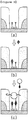
- FIG. 1 is a schematic view of the method for detecting a molecule using the interdigitated electrode sensor according to the present invention.
- the interdigitated electrode biosensor is prepared by forming interdigitated electrode pattern on a substrate so that electrodes are opposed to each other (a).
- the interdigitated electrode pattern is transformed into nanogap interdigitated electrodes by reduction process (b).
- Sensor-immobilized biomolecule receptors are immobilized on the substrate exposed between the nanogap interdigitated electrodes through the media of the linker molecule layer (Self Assembled Monolayer) to form a biosensor (c).
- a sample solution is contacted with the biosensor so that a biomolecule in the sample solution specifically binds to the sensor-immobilized biomolecule receptor (d).
- particle-immobilized biomolecule receptor (same as the sensor-immobilized biomolecule receptor) having conductive nano-particles immobilized thereon binds to the biomolecule, whereby the first electrode and the second electrode are electrically connected (e).
- FIG. 2 illustrates the large area interdigitated electrodes engaged with each other according to the present invention, in which the area where the nano-particles may be immobilized is enlarged by increasing the total length of the interdigitated electrode area while maintaining the electrode gap of the interdigitated electrode sensor according to the present invention in a range of 5 nm to several tens of nm, for rapid detection of antigen at a low concentration.
- the first electrode and the second electrode are repeatedly alternated with each other while maintaining a uniform distance and opposed to each other so that the opposed area of the first electrode and the second electrode is increased.
- the substrate area exposed between the two electrodes is an area where the sensor-immobilized biomolecule receptor which can specifically bind to the biomolecule is immobilized.
- the method for forming the nanogap device having such structure includes a chemical reduction gap narrowing step to raise yield and reduce the unit cost of production .
- methods for highly integrating nanogap sensors may be selected.
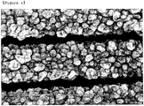
- FIG. 3 and FIG. 4 are photographs of the interdigitated electrode when antigen is present in a subject sample and when antigen is not present in a subject sample.
- FIG. 3 shows a number of nano-particles captured between nanogap electrodes having a gap of about 50 nm prepared by the gap narrowing process. This is the result that antigen contained in the subject sample is captured by antibody attached onto the surface of the nanogap electrodes and the antigen then binds to antibody having electrically conductive nano-particle, consequently showing nano-particles immobilized between the electrodes.
- FIG. 3 shows a number of nano-particles captured between nanogap electrodes having a gap of about 50 nm prepared by the gap narrowing process. This is the result that antigen contained in the subject sample is captured by antibody attached onto the surface of the nanogap electrodes and the antigen then binds to antibody having electrically conductive nano-particle, consequently showing nano-particles immobilized between the electrodes.
- FIG. 3 shows
- FIG. 4 is an electron microscopic photograph of a sample measured by using the nanogap interdigitated electrode sensor unit and performing the same process as for FIG. 3 , except that the sample does not contain antigen which can selectively bind to antibody.
- the sample does not contain antigen which can selectively bind to antibody.
- nano-particles are not immobilized since the subject sample does not contain antigen which can selectively bind to antibody.
- the particle-immobilized biomolecule receptor having electrically conductive particles immobilized in the gap between interdigitated electrodes may induce change in electrical conductivity between two electrodes.
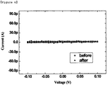
- FIG. 5 and FIG. 6 show changes in electrical conductivity of the nanogap sensor according to binding of the particle-immobilized biomolecule receptor.
- FIG. 5 is an I-V graph showing before and after contact between the biosensor according to the present invention and the biomolecule (antigen) containing sample, in which the electrical conductivity is increased by the particle-immobilized biomolecule receptor binding to the biomolecule. Since the I-V graph after the contact with the biomolecule has a uniform gradient, it can be indirectly confirmed that the electrical conductivity is increased by an electron transport phenomenon by the media of the electrically conductive metallic nano-particles.
- FIG. 6 shows the change in the I-V graph before and after contact with the biosensor according to the present invention and a subject sample when the biomolecule is not present in the subject sample. It is shown that the electrical conductivity does not change when the biomolecule is not present in a subject sample, unlike FIG. 5 .
- FIG. 7 is a schematic view for description of the method for measuring the concentration of a subject material from statistical data of electrical conductivity showing the on-off state of the interdigitated electrode sensor units by integrating the sensor units with m ranks and n columns.
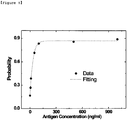
- FIG. 8 is a graph showing the correlation between the rate of the device showing electrical characteristics variation signal and the concentration of antigen, in which the measured rate of the interdigitated electrode sensor units causing the change in the electrical conductivity according to the concentration of the antigen on the nanogap biosensor antigen is plotted.
- the dotted curve is calculated by the following equation. It is confirmed that the experimental result agrees well with the result estimated by the equation.
- P on A - B ⁇ exp - kC
- a and B refer constants reflecting non-ideal behavior of the sensor which may be caused by several factors such as imperfection of the device, immobilization efficiency of nano-particles and non-specific bonding]
- FIG. 9 is a schematic view showing another method for quantitatively analyzing a biomolecule according to the present invention, in which the measurement step is opposed to the method described in FIG. 1 . In the following, the method is described in detail with reference to FIG. 9 .
- the biosensor according to the present invention is contacted with a sample solution containing a subject biomolecule (a).
- the biomolecule is captured by sensor-immobilized biomolecule receptors immobilized on a substrate (b).
- the biosensor is contacted with another biomolecule having electrically conductive particles fixed thereon.
- the electrically-conductive-particle-fixed biomolecule is captured by sensor-immobilized biomolecule receptor where the subject biomolecule has not been captured.
- the first electrode and the second electrode are electrically connected by the electrically conductive particle (c). Therefore, the biomolecule in the sample solution can be analyzed by measuring the number of electrically connected interdigitated electrode sensor units or the number of non-connected interdigitated electrode sensor units. The method shown in FIG.
- FIG. 10 (b) can be effectively used in measurement of biomolecule in a high concentration range as shown in FIG. 10 (b) .
- This method can overcome the low sensitivity problem appearing when the biomolecule exists at a high concentration in a quantitative analysis of the biomolecule by the method of FIG. 1 ( FIG. 10 (a) ).
- the biosensor according to the present invention can contribute to various fields such as development of material detection technique based on molecular recognition, kit for early diagnosis of diseases, environment monitoring systems, public health and hygiene supervision apparatus, sensor systems for anti-terror and against chemical, biological and radiological warfare, and development of sensor kits.
- the present invention can provide the highest performance by combination with technique for pre-treatment of reagent such as blood and optimized surface control technique, technique for complex treatment of signals and be conveniently manufactured in a large scale.
- the present invention it is possible to detect a small amount of biomolecule in high concentration and low concentration ranges by producing a large area nanogap device by reducing the gap space of the nanogap device and increasing the surface area of the nanogap to shorten the detection time while maintaining detection sensitivity of the device.
Landscapes
- Health & Medical Sciences (AREA)
- Life Sciences & Earth Sciences (AREA)
- Immunology (AREA)
- Engineering & Computer Science (AREA)
- Chemical & Material Sciences (AREA)
- Molecular Biology (AREA)
- Biomedical Technology (AREA)
- Hematology (AREA)
- Urology & Nephrology (AREA)
- Physics & Mathematics (AREA)
- Pathology (AREA)
- Analytical Chemistry (AREA)
- General Physics & Mathematics (AREA)
- General Health & Medical Sciences (AREA)
- Biochemistry (AREA)
- Cell Biology (AREA)
- Medicinal Chemistry (AREA)
- Food Science & Technology (AREA)
- Microbiology (AREA)
- Biotechnology (AREA)
- Spectroscopy & Molecular Physics (AREA)
- Chemical Kinetics & Catalysis (AREA)
- Electrochemistry (AREA)
- Inorganic Chemistry (AREA)
- Investigating Or Analyzing Materials By The Use Of Electric Means (AREA)
- Apparatus Associated With Microorganisms And Enzymes (AREA)
- Investigating Or Analyzing Materials By The Use Of Fluid Adsorption Or Reactions (AREA)
Claims (16)
- Biosensor, umfassend eine Vielzahl von unabhängig arbeitenden interdigitalen Elektrodensensoreinheiten, die an einem Substrat integriert sind, wobei die interdigitalen Elektrodensensoreinheiten umfassen:erste Elektrode und zweite Elektrode, die interdigital und voneinander beabstandet an dem Substrat ausgebildet sind, undeinen Sensor-immobilisierten Biomolekülrezeptor, der an dem Substrat immobilisiert ist, das zwischen der ersten Elektrode und der zweiten Elektrode exponiert ist, so dass die erste Elektrode bei Bindung an ein Biomolekül und spezifischer Bindung an das Biomolekül elektrisch mit der zweiten Elektrode verbunden werden kann,wobei die erste Elektrode und die zweite Elektrode gebildet werden, indem das Substrat, das ein interdigitales Metallmuster darauf hat, in eine Lösung, die Metallion enthält, eingetaucht wird und ein Reduktionsmittel zu der Lösung gegeben wird, um das Metall, das aus dem Metallion in der Lösung reduziert wurde, an der Oberfläche mit dem Metallmuster wachsen zu lassen, und das Biomolekül durch eine Reihe der interdigitalen Elektrodensensoreinheiten, die elektrisch durch das Biomolekül, das durch den Sensor-immobilisierten Biomolekülrezeptor eingefangen wurde, elektrisch verbunden werden, analysiert werden kann.
- Biosensor gemäß Anspruch 1, wobei der Biomolekülrezeptor des Sensor-immobilisierten Biomolekülrezeptors ein Antikörper ist und das Biomolekül ein Antigen ist.
- Biosensor gemäß Anspruch 2, wobei der Sensorimmobilisierte Biomolekülrezeptor verschiedene Antikörpertypen, die an dem Substrat immobilisiert sind, bei einem vorbestimmten Verhältnis umfasst.
- Biosensor gemäß Anspruch 1, wobei der Abstand zwischen der ersten Elektrode und der zweiten Elektrode 1 nm bis 100 nm ist.
- Biosensor gemäß Anspruch 1, wobei die erste Elektrode und die zweite Elektrode mit einer Proteinadsorptionblockierenden Schicht an der Oberfläche versehen sind.
- Biosensor gemäß Anspruch 1, wobei der Sensorimmobilisierte Biomolekülrezeptor und das Substrat durch eine Linkermolekülschicht fixiert sind.
- Biosensor gemäß Anspruch 1, wobei die erste Elektrode und die zweite Elektrode eine Höhe haben, die größer ist als die Höhe des Biomolekülrezeptors, der an dem Substrat immobilisiert ist.
- Biosensor gemäß Anspruch 1, wobei das Metallmuster aus Au, Ag, Al, Cu und Pt ausgewählt ist.
- Biosensor gemäß Anspruch 1, wobei die Reduktion des Metallions durchgeführt wird, indem ein Reduktionsmittel, ausgewählt aus Hydroxylamin (H2NOH), Ascorbinsäure, Glucose, Rochelle-Salz (Kaliumnatriumtartrat), Formaldehyd und Gemischen davon, zu der Lösung gegeben wird.
- Verfahren zum Analysieren eines Biomoleküls, umfassend die Schritte:Inkontaktbringen des Biosensors gemäß Anspruch 1 mit einer Probenlösung, die das zu analysierende Biomolekül enthält, so dass das Biomolekül durch einen Sensor-immobilisierten Biomolekülrezeptor, der an einem Substrat immobilisiert ist, das zwischen erster Elektrode und zweiter Elektrode einer unabhängig arbeitenden interdigitalen Elektrodensensoreinheit exponiert ist, eingefangen wird;Inkontaktbringen des Biomoleküls, das an den Sensor-immobilisierten Biomolekülrezeptor gebunden ist, mit einem Partikel-immobilisierten Biomolekülrezeptor, der ein elektrisch leitendes Partikel daran immobilisiert hat, um das Biomolekül zu binden;wobei die erste Elektrode und die zweite Elektrode durch das elektrisch leitende Partikel elektrisch verbunden sind,Messen der elektrischen Leitfähigkeit des Biosensors undErrechnen der Konzentration des Biomoleküls in der Probenlösung aus der Beziehung zwischen der Konzentration und der Rate der Sensoren, die eine Änderung der elektrischen Leitfähigkeit vor und nach Kontakt mit der Lösung zeigen.
- Verfahren zum Analysieren eines Biomoleküls, umfassend die Schritte:Immobilisieren eines elektrisch leitenden Partikels an dem Subjektbiomolekül;Inkontaktbringen des Biosensors gemäß Anspruch 1 mit dem Subjektbiomolekül, das ein elektrisch leitendes Partikel daran immobilisiert hat, so dass das Subjektbiomolekül durch einen Sensor-immobilisierten Biomolekülrezeptor eingefangen wird, welcher an einem Substrat immobilisiert ist, das zwischen erster Elektrode und zweiter Elektrode einer unabhängig arbeitenden interdigitalen Elektrodensensoreinheit exponiert ist;wodurch die erste Elektrode und die zweite Elektrode durch das elektrisch leitende Partikel elektrisch verbunden werden,Messen der elektrischen Leitfähigkeit des Biosensors undErrechnen der Konzentration des Biomoleküls in der Probenlösung aus der Beziehung zwischen der Konzentration und der Rate der Sensoren, die eine Änderung der elektrischen Leitfähigkeit vor und nach Kontakt mit der Lösung zeigen.
- Verfahren zum Analysieren eines Biomoleküls, umfassend die Schritte:Inkontaktbringen des Biosensors gemäß Anspruch 1 mit einer zu analysierenden Probe, so dass das Subjektbiomolekül durch einen Sensor-immobilisierten Biomolekülrezeptor eingefangen wird, welcher an einem Substrat immobilisiert ist, das zwischen erster Elektrode und zweiter Elektrode einer unabhängig arbeitenden interdigitalen Elektrodensensoreinheit exponiert ist;Inkontaktbringen des Biosensors mit einem anderen Biomolekül, das ein elektrisch leitendes Partikel daran immobilisiert hat, so dass das elektrisch leitende Partikel-immobilisierte Biomolekül durch den Sensor-immobilisierten Biomolekülrezeptor, wo das Subjektbiomolekül nicht eingefangen wurde, eingefangen wird;wodurch die erste Elektrode und die zweite Elektrode durch das elektrisch leitende Partikel elektrisch verbunden werden,Messen der elektrischen Leitfähigkeit des Biosensors undErrechnen der Konzentration des Biomoleküls in der Probenlösung aus der Beziehung zwischen der Konzentration und der Rate der Sensoren, die eine Änderung der elektrischen Leitfähigkeit vor und nach Kontakt mit der Probenlösung zeigen.
- Verfahren gemäß einem der Ansprüche 10 bis 12, wobei das Biomolekül in einer Probenlösung durch Korrelation zwischen der Konzentration des Biomoleküls in einer Probenlösung und dem Verhältnis der Anzahl der elektrisch verbundenen interdigitalen Elektrodensensoreinheiten zu der Gesamtzahl der interdigitalen Elektrodensensoreinheiten analysiert wird.
- Verfahren gemäß einem der Ansprüche 10 bis 13, wobei der Biomolekülrezeptor des Sensor-immobilisierten Biomolekülrezeptors und der Partikel-immobilisierte Biomolekülrezeptor ein Antikörper ist und das Biomolekül ein Antigen ist.
- Verfahren gemäß einem der Ansprüche 10 bis 14, wobei das elektrisch leitende Partikel, das an dem Biomolekül immobilisiert ist, oder der Partikel-immobilisierte Biomolekülrezeptor eine Größe von 0,5 nm bis 1 µm hat.
- Verfahren gemäß Anspruch 15, wobei das elektrisch leitende Partikel, das an dem Partikel-immobilisierten Biomolekülrezeptor immobilisiert ist, eine Größe von 1 nm bis 100 nm hat.
Applications Claiming Priority (2)
| Application Number | Priority Date | Filing Date | Title |
|---|---|---|---|
| KR1020060065828A KR100777973B1 (ko) | 2006-07-13 | 2006-07-13 | 다중선형전극 센서 유닛으로 이루어진 바이오센서 |
| PCT/KR2006/003357 WO2008007822A1 (en) | 2006-07-13 | 2006-08-25 | Biosensor comprising interdigitated electrode sensor units |
Publications (3)
| Publication Number | Publication Date |
|---|---|
| EP2047259A1 EP2047259A1 (de) | 2009-04-15 |
| EP2047259A4 EP2047259A4 (de) | 2010-01-06 |
| EP2047259B1 true EP2047259B1 (de) | 2012-04-18 |
Family
ID=38923374
Family Applications (1)
| Application Number | Title | Priority Date | Filing Date |
|---|---|---|---|
| EP06783744A Not-in-force EP2047259B1 (de) | 2006-07-13 | 2006-08-25 | Biosensor mit interdigitalen elektrodensensoreinheiten |
Country Status (6)
| Country | Link |
|---|---|
| US (1) | US20090084686A1 (de) |
| EP (1) | EP2047259B1 (de) |
| JP (1) | JP2009543090A (de) |
| KR (1) | KR100777973B1 (de) |
| AT (1) | ATE554387T1 (de) |
| WO (1) | WO2008007822A1 (de) |
Families Citing this family (26)
| Publication number | Priority date | Publication date | Assignee | Title |
|---|---|---|---|---|
| WO2009023857A1 (en) * | 2007-08-15 | 2009-02-19 | State Of Oregon By & Through The State Board Of Higher Education On Behalf Of Portland State Unv. | Impedance spectroscopy of biomolecules using functionalized nanoparticles |
| KR100937260B1 (ko) * | 2007-12-31 | 2010-01-15 | 한국표준과학연구원 | 나노갭 전극을 이용한 나노입자 검출센서 |
| KR100988728B1 (ko) | 2008-10-15 | 2010-10-20 | 한국과학기술원 | 생분자의 선택성을 이용한 바이오 센서 |
| US9465003B2 (en) * | 2010-12-16 | 2016-10-11 | Korea Research Institute Of Bioscience And Biotechnology | Membrane phase electrode using printing and bio-molecule detection using same |
| CA2856380C (en) * | 2011-11-22 | 2020-05-12 | Siemens Healthcare Diagnostics Inc. | Interdigitated array and method of manufacture |
| KR101484822B1 (ko) | 2012-12-07 | 2015-01-21 | 한양대학교 산학협력단 | 세포 계수 장치 및 이의 제조방법 |
| EP2972333B1 (de) * | 2013-03-11 | 2018-09-19 | The University of Toledo | Biosensorvorrichtung zur abzielung auf analyten in situ, in vivo, und/oder in echtzeit und verfahren zur herstellung und verwendung davon |
| CN103592344A (zh) * | 2013-05-10 | 2014-02-19 | 北京师范大学 | 碳纳米管传感器及其制造方法 |
| US10145846B2 (en) | 2014-04-16 | 2018-12-04 | Arizona Board Of Regents On Behalf Of Arizona State University | Digital protein sensing chip and methods for detection of low concentrations of molecules |
| KR101648383B1 (ko) | 2014-09-19 | 2016-08-24 | 한국과학기술연구원 | 교차전극 바이오센서 |
| WO2016176216A1 (en) * | 2015-04-27 | 2016-11-03 | Cbrite Inc. | Motft and array circuit for chemical/biochemical applications |
| KR101709914B1 (ko) | 2015-11-24 | 2017-02-27 | 한국과학기술연구원 | 하이드로젤을 이용한 교차 전극 바이오센서 |
| KR101754239B1 (ko) | 2015-12-28 | 2017-07-06 | 한국과학기술연구원 | 수용체와 표적 생체물질의 반응을 이용한 교차 전극 바이오센서 |
| KR101727107B1 (ko) * | 2016-02-19 | 2017-04-17 | 한국과학기술연구원 | 유전체 전기영동을 이용한 마이크로 전극 바이오 센서 |
| KR101866060B1 (ko) * | 2016-09-26 | 2018-06-08 | 울산과학기술원 | 유전영동 기반의 바이오 센서 |
| WO2018106129A1 (en) * | 2016-12-09 | 2018-06-14 | Digital Sensing Limited | Electrochemical sensors and methods of use thereof |
| WO2018152296A1 (en) | 2017-02-15 | 2018-08-23 | New Jersey Institute Of Technology | Enhanced sensitivity and specificity for point-of-care (poc) micro biochip |
| US11020740B2 (en) * | 2017-10-24 | 2021-06-01 | New Jersey Institute Of Technology | Microfluidic biochip with enhanced sensitivity |
| GB2573323A (en) * | 2018-05-03 | 2019-11-06 | Mursia Ltd | Biosensor method and system |
| NL2025067B1 (en) * | 2019-03-05 | 2021-05-31 | Univ Twente | Sensor for single particle detection |
| US11255805B2 (en) | 2019-12-23 | 2022-02-22 | Nanodx, Inc. | Sensor system and methods |
| KR102447193B1 (ko) * | 2020-05-07 | 2022-09-23 | 성균관대학교산학협력단 | 멀티 갭 전기화학 센서 및 이를 이용한 정량분석 방법 |
| WO2022224255A1 (en) * | 2021-04-19 | 2022-10-27 | B. G. Negev Technologies And Applications Ltd., At Ben-Gurion University | Monocrystalline gold microplates methods of fabrication thereof and devices comprising same |
| CN114858889A (zh) * | 2022-04-13 | 2022-08-05 | 常州先趋医疗科技有限公司 | Ide叉指电极的制作以及预功能化处理方法 |
| CN116725485A (zh) * | 2023-05-26 | 2023-09-12 | 苏州能斯达电子科技有限公司 | 一种嵌入式织物基柔性可穿戴液体传感器及检测方法 |
| CN119666934B (zh) * | 2024-12-13 | 2026-02-24 | 太原理工大学 | 一种基于叉指电极的五羟色胺表面应力生物传感器及其制备方法 |
Family Cites Families (22)
| Publication number | Priority date | Publication date | Assignee | Title |
|---|---|---|---|---|
| US4279775A (en) * | 1979-12-31 | 1981-07-21 | Louderback Allan Lee | Blood gas control |
| US4794089A (en) * | 1986-03-25 | 1988-12-27 | Midwest Research Microscopy, Inc. | Method for electronic detection of a binding reaction |
| KR0151203B1 (ko) * | 1994-12-08 | 1998-12-01 | 이헌조 | 다중전극형 바이오센서 |
| US6506564B1 (en) * | 1996-07-29 | 2003-01-14 | Nanosphere, Inc. | Nanoparticles having oligonucleotides attached thereto and uses therefor |
| US6974669B2 (en) * | 2000-03-28 | 2005-12-13 | Nanosphere, Inc. | Bio-barcodes based on oligonucleotide-modified nanoparticles |
| KR100294678B1 (ko) * | 1999-01-22 | 2001-07-03 | 구자홍 | 전기전도도 측정식 면역센서 |
| WO2001003208A1 (en) * | 1999-07-02 | 2001-01-11 | President And Fellows Of Harvard College | Nanoscopic wire-based devices, arrays, and methods of their manufacture |
| KR20030055346A (ko) * | 2000-12-11 | 2003-07-02 | 프레지던트 앤드 펠로우즈 오브 하버드 칼리지 | 나노센서 |
| US6824974B2 (en) * | 2001-06-11 | 2004-11-30 | Genorx, Inc. | Electronic detection of biological molecules using thin layers |
| US6653653B2 (en) * | 2001-07-13 | 2003-11-25 | Quantum Logic Devices, Inc. | Single-electron transistors and fabrication methods in which a projecting feature defines spacing between electrodes |
| US20030203384A1 (en) * | 2002-03-08 | 2003-10-30 | Chafin David R. | Multiplex detection of biological materials in a sample |
| US20040110277A1 (en) * | 2002-04-12 | 2004-06-10 | Seiko Epson Corporation | Sensor cell, bio-sensor, capacitance element manufacturing method, biological reaction detection method and genetic analytical method |
| US20040029288A1 (en) * | 2002-08-09 | 2004-02-12 | Arthur Snow | Nonlinear gold nanocluster chemical vapor sensor |
| WO2004042070A2 (en) * | 2002-05-14 | 2004-05-21 | Nanosphere, Inc. | Electrical detection of dna hybridization and specific binding events |
| EP1516175B1 (de) * | 2002-06-24 | 2006-11-02 | Siemens Aktiengesellschaft | Biosensor-array und verfahren zum betreiben eines biosensor-arrays |
| EP1376111A1 (de) * | 2002-06-24 | 2004-01-02 | Universite Catholique De Louvain | Verfahren und Vorrichtung für die hochempfindliche Bestimmung von DNA und anderen Testsubstanzen |
| US20050272989A1 (en) * | 2004-06-04 | 2005-12-08 | Medtronic Minimed, Inc. | Analyte sensors and methods for making and using them |
| WO2004068389A2 (en) * | 2003-01-28 | 2004-08-12 | Conductive Inkjet Technology Limited | Method of forming a conductive metal region on a substrate |
| DE10328136A1 (de) * | 2003-06-23 | 2005-01-27 | Infineon Technologies Ag | Sensor-Element, Sensor-Array und Verfahren zum Erfassen von in einem Analyten möglicherweise enthaltenen Partikeln |
| US20050059105A1 (en) * | 2003-07-25 | 2005-03-17 | Board Of Trustees Of Michigan State University | Impedimetric biosensor and its use for rapid detection of bacterial pathogens in solution |
| US20050244811A1 (en) * | 2003-12-15 | 2005-11-03 | Nano-Proprietary, Inc. | Matrix array nanobiosensor |
| EP1982166A4 (de) * | 2006-01-20 | 2010-06-30 | Agency Science Tech & Res | Biosensor-zelle und biosensor-array |
-
2006
- 2006-07-13 KR KR1020060065828A patent/KR100777973B1/ko not_active Expired - Fee Related
- 2006-08-25 WO PCT/KR2006/003357 patent/WO2008007822A1/en not_active Ceased
- 2006-08-25 JP JP2009519350A patent/JP2009543090A/ja active Pending
- 2006-08-25 EP EP06783744A patent/EP2047259B1/de not_active Not-in-force
- 2006-08-25 AT AT06783744T patent/ATE554387T1/de active
- 2006-08-25 US US11/991,083 patent/US20090084686A1/en not_active Abandoned
Also Published As
| Publication number | Publication date |
|---|---|
| JP2009543090A (ja) | 2009-12-03 |
| KR100777973B1 (ko) | 2007-11-29 |
| US20090084686A1 (en) | 2009-04-02 |
| ATE554387T1 (de) | 2012-05-15 |
| EP2047259A4 (de) | 2010-01-06 |
| WO2008007822A1 (en) | 2008-01-17 |
| EP2047259A1 (de) | 2009-04-15 |
Similar Documents
| Publication | Publication Date | Title |
|---|---|---|
| EP2047259B1 (de) | Biosensor mit interdigitalen elektrodensensoreinheiten | |
| Hao et al. | Modulating the linker immobilization density on aptameric graphene field effect transistors using an electric field | |
| Poghossian et al. | Label‐free sensing of biomolecules with field‐effect devices for clinical applications | |
| Patolsky et al. | Nanowire sensors for medicine and the life sciences | |
| Merkoçi | Electrochemical biosensing with nanoparticles | |
| Cheng et al. | Nanotechnologies for biomolecular detection and medical diagnostics | |
| Xu et al. | Label-free electrochemical detection for aptamer-based array electrodes | |
| Tang et al. | Fabrication of immunosensor microwell arrays from gold compact discs for detection of cancer biomarker proteins | |
| JP5985654B2 (ja) | 選択的表面固定化部位を有するナノギャップ・トランスデューサ | |
| JP3874772B2 (ja) | 生体関連物質測定装置及び測定方法 | |
| EP1516174B1 (de) | Verfahren und einrichtung zur hochempfindlichen detektion der anwesenheit von dna und weitere sonden | |
| US12469324B2 (en) | Semiconductor device with biofet and biometric sensors | |
| US20170234825A1 (en) | High throughput biochemical detection using single molecule fingerprinting arrays | |
| US9841416B2 (en) | Systems and methods for single-molecule nucleic-acid assay platforms | |
| US20020123048A1 (en) | Biological identification system with integrated sensor chip | |
| US9434983B2 (en) | Nano-sensor array | |
| WO2011017077A9 (en) | Nanochannel-based sensor system with controlled sensitivity | |
| Rani et al. | Top-down fabricated silicon nanowire arrays for field-effect detection of prostate-specific antigen | |
| CN110954585B (zh) | 生物场效应晶体管传感器的差动式感测 | |
| Liu et al. | Probe-screened carbon nanotube field-effect transistor biosensor to enhance breast cancer-related gene assay | |
| US20200088723A1 (en) | Differential sensor measurement methods and devices | |
| NL2025067B1 (en) | Sensor for single particle detection | |
| US12025581B2 (en) | Devices and methods for detecting/discriminating complementary and mismatched nucleic acids using ultrathin film field-effect transistors | |
| US11275050B2 (en) | Semiconductor-based biosensor and detection methods | |
| JP2012211819A (ja) | バイオセンサ |
Legal Events
| Date | Code | Title | Description |
|---|---|---|---|
| PUAI | Public reference made under article 153(3) epc to a published international application that has entered the european phase |
Free format text: ORIGINAL CODE: 0009012 |
|
| 17P | Request for examination filed |
Effective date: 20090210 |
|
| AK | Designated contracting states |
Kind code of ref document: A1 Designated state(s): AT BE BG CH CY CZ DE DK EE ES FI FR GB GR HU IE IS IT LI LT LU LV MC NL PL PT RO SE SI SK TR |
|
| AX | Request for extension of the european patent |
Extension state: AL BA HR MK RS |
|
| A4 | Supplementary search report drawn up and despatched |
Effective date: 20091208 |
|
| 17Q | First examination report despatched |
Effective date: 20100305 |
|
| REG | Reference to a national code |
Ref country code: DE Ref legal event code: R079 Ref document number: 602006028961 Country of ref document: DE Free format text: PREVIOUS MAIN CLASS: G01N0033530000 Ipc: G01N0033543000 |
|
| RIC1 | Information provided on ipc code assigned before grant |
Ipc: C12Q 1/68 20060101ALI20110818BHEP Ipc: G01N 33/543 20060101AFI20110818BHEP |
|
| GRAP | Despatch of communication of intention to grant a patent |
Free format text: ORIGINAL CODE: EPIDOSNIGR1 |
|
| DAX | Request for extension of the european patent (deleted) | ||
| GRAS | Grant fee paid |
Free format text: ORIGINAL CODE: EPIDOSNIGR3 |
|
| GRAA | (expected) grant |
Free format text: ORIGINAL CODE: 0009210 |
|
| AK | Designated contracting states |
Kind code of ref document: B1 Designated state(s): AT BE BG CH CY CZ DE DK EE ES FI FR GB GR HU IE IS IT LI LT LU LV MC NL PL PT RO SE SI SK TR |
|
| REG | Reference to a national code |
Ref country code: GB Ref legal event code: FG4D |
|
| REG | Reference to a national code |
Ref country code: CH Ref legal event code: EP |
|
| REG | Reference to a national code |
Ref country code: IE Ref legal event code: FG4D |
|
| REG | Reference to a national code |
Ref country code: AT Ref legal event code: REF Ref document number: 554387 Country of ref document: AT Kind code of ref document: T Effective date: 20120515 |
|
| REG | Reference to a national code |
Ref country code: DE Ref legal event code: R096 Ref document number: 602006028961 Country of ref document: DE Effective date: 20120614 |
|
| REG | Reference to a national code |
Ref country code: NL Ref legal event code: VDEP Effective date: 20120418 |
|
| REG | Reference to a national code |
Ref country code: AT Ref legal event code: MK05 Ref document number: 554387 Country of ref document: AT Kind code of ref document: T Effective date: 20120418 |
|
| LTIE | Lt: invalidation of european patent or patent extension |
Effective date: 20120418 |
|
| PG25 | Lapsed in a contracting state [announced via postgrant information from national office to epo] |
Ref country code: LT Free format text: LAPSE BECAUSE OF FAILURE TO SUBMIT A TRANSLATION OF THE DESCRIPTION OR TO PAY THE FEE WITHIN THE PRESCRIBED TIME-LIMIT Effective date: 20120418 Ref country code: IS Free format text: LAPSE BECAUSE OF FAILURE TO SUBMIT A TRANSLATION OF THE DESCRIPTION OR TO PAY THE FEE WITHIN THE PRESCRIBED TIME-LIMIT Effective date: 20120818 Ref country code: PL Free format text: LAPSE BECAUSE OF FAILURE TO SUBMIT A TRANSLATION OF THE DESCRIPTION OR TO PAY THE FEE WITHIN THE PRESCRIBED TIME-LIMIT Effective date: 20120418 Ref country code: CY Free format text: LAPSE BECAUSE OF FAILURE TO SUBMIT A TRANSLATION OF THE DESCRIPTION OR TO PAY THE FEE WITHIN THE PRESCRIBED TIME-LIMIT Effective date: 20120418 Ref country code: SE Free format text: LAPSE BECAUSE OF FAILURE TO SUBMIT A TRANSLATION OF THE DESCRIPTION OR TO PAY THE FEE WITHIN THE PRESCRIBED TIME-LIMIT Effective date: 20120418 Ref country code: FI Free format text: LAPSE BECAUSE OF FAILURE TO SUBMIT A TRANSLATION OF THE DESCRIPTION OR TO PAY THE FEE WITHIN THE PRESCRIBED TIME-LIMIT Effective date: 20120418 |
|
| PGFP | Annual fee paid to national office [announced via postgrant information from national office to epo] |
Ref country code: GB Payment date: 20120725 Year of fee payment: 7 |
|
| PG25 | Lapsed in a contracting state [announced via postgrant information from national office to epo] |
Ref country code: PT Free format text: LAPSE BECAUSE OF FAILURE TO SUBMIT A TRANSLATION OF THE DESCRIPTION OR TO PAY THE FEE WITHIN THE PRESCRIBED TIME-LIMIT Effective date: 20120820 Ref country code: GR Free format text: LAPSE BECAUSE OF FAILURE TO SUBMIT A TRANSLATION OF THE DESCRIPTION OR TO PAY THE FEE WITHIN THE PRESCRIBED TIME-LIMIT Effective date: 20120719 Ref country code: LV Free format text: LAPSE BECAUSE OF FAILURE TO SUBMIT A TRANSLATION OF THE DESCRIPTION OR TO PAY THE FEE WITHIN THE PRESCRIBED TIME-LIMIT Effective date: 20120418 Ref country code: SI Free format text: LAPSE BECAUSE OF FAILURE TO SUBMIT A TRANSLATION OF THE DESCRIPTION OR TO PAY THE FEE WITHIN THE PRESCRIBED TIME-LIMIT Effective date: 20120418 |
|
| PG25 | Lapsed in a contracting state [announced via postgrant information from national office to epo] |
Ref country code: BE Free format text: LAPSE BECAUSE OF FAILURE TO SUBMIT A TRANSLATION OF THE DESCRIPTION OR TO PAY THE FEE WITHIN THE PRESCRIBED TIME-LIMIT Effective date: 20120418 |
|
| PGFP | Annual fee paid to national office [announced via postgrant information from national office to epo] |
Ref country code: DE Payment date: 20120727 Year of fee payment: 7 Ref country code: FR Payment date: 20120808 Year of fee payment: 7 |
|
| PG25 | Lapsed in a contracting state [announced via postgrant information from national office to epo] |
Ref country code: NL Free format text: LAPSE BECAUSE OF FAILURE TO SUBMIT A TRANSLATION OF THE DESCRIPTION OR TO PAY THE FEE WITHIN THE PRESCRIBED TIME-LIMIT Effective date: 20120418 Ref country code: DK Free format text: LAPSE BECAUSE OF FAILURE TO SUBMIT A TRANSLATION OF THE DESCRIPTION OR TO PAY THE FEE WITHIN THE PRESCRIBED TIME-LIMIT Effective date: 20120418 Ref country code: EE Free format text: LAPSE BECAUSE OF FAILURE TO SUBMIT A TRANSLATION OF THE DESCRIPTION OR TO PAY THE FEE WITHIN THE PRESCRIBED TIME-LIMIT Effective date: 20120418 Ref country code: SK Free format text: LAPSE BECAUSE OF FAILURE TO SUBMIT A TRANSLATION OF THE DESCRIPTION OR TO PAY THE FEE WITHIN THE PRESCRIBED TIME-LIMIT Effective date: 20120418 Ref country code: RO Free format text: LAPSE BECAUSE OF FAILURE TO SUBMIT A TRANSLATION OF THE DESCRIPTION OR TO PAY THE FEE WITHIN THE PRESCRIBED TIME-LIMIT Effective date: 20120418 Ref country code: CZ Free format text: LAPSE BECAUSE OF FAILURE TO SUBMIT A TRANSLATION OF THE DESCRIPTION OR TO PAY THE FEE WITHIN THE PRESCRIBED TIME-LIMIT Effective date: 20120418 Ref country code: AT Free format text: LAPSE BECAUSE OF FAILURE TO SUBMIT A TRANSLATION OF THE DESCRIPTION OR TO PAY THE FEE WITHIN THE PRESCRIBED TIME-LIMIT Effective date: 20120418 |
|
| PLBE | No opposition filed within time limit |
Free format text: ORIGINAL CODE: 0009261 |
|
| STAA | Information on the status of an ep patent application or granted ep patent |
Free format text: STATUS: NO OPPOSITION FILED WITHIN TIME LIMIT |
|
| PG25 | Lapsed in a contracting state [announced via postgrant information from national office to epo] |
Ref country code: IT Free format text: LAPSE BECAUSE OF FAILURE TO SUBMIT A TRANSLATION OF THE DESCRIPTION OR TO PAY THE FEE WITHIN THE PRESCRIBED TIME-LIMIT Effective date: 20120418 |
|
| 26N | No opposition filed |
Effective date: 20130121 |
|
| REG | Reference to a national code |
Ref country code: CH Ref legal event code: PL |
|
| PG25 | Lapsed in a contracting state [announced via postgrant information from national office to epo] |
Ref country code: MC Free format text: LAPSE BECAUSE OF NON-PAYMENT OF DUE FEES Effective date: 20120831 |
|
| PG25 | Lapsed in a contracting state [announced via postgrant information from national office to epo] |
Ref country code: CH Free format text: LAPSE BECAUSE OF NON-PAYMENT OF DUE FEES Effective date: 20120831 Ref country code: ES Free format text: LAPSE BECAUSE OF FAILURE TO SUBMIT A TRANSLATION OF THE DESCRIPTION OR TO PAY THE FEE WITHIN THE PRESCRIBED TIME-LIMIT Effective date: 20120729 Ref country code: LI Free format text: LAPSE BECAUSE OF NON-PAYMENT OF DUE FEES Effective date: 20120831 |
|
| REG | Reference to a national code |
Ref country code: DE Ref legal event code: R097 Ref document number: 602006028961 Country of ref document: DE Effective date: 20130121 |
|
| REG | Reference to a national code |
Ref country code: IE Ref legal event code: MM4A |
|
| PG25 | Lapsed in a contracting state [announced via postgrant information from national office to epo] |
Ref country code: IE Free format text: LAPSE BECAUSE OF NON-PAYMENT OF DUE FEES Effective date: 20120825 Ref country code: BG Free format text: LAPSE BECAUSE OF FAILURE TO SUBMIT A TRANSLATION OF THE DESCRIPTION OR TO PAY THE FEE WITHIN THE PRESCRIBED TIME-LIMIT Effective date: 20120718 |
|
| GBPC | Gb: european patent ceased through non-payment of renewal fee |
Effective date: 20130825 |
|
| PG25 | Lapsed in a contracting state [announced via postgrant information from national office to epo] |
Ref country code: DE Free format text: LAPSE BECAUSE OF NON-PAYMENT OF DUE FEES Effective date: 20140301 Ref country code: TR Free format text: LAPSE BECAUSE OF FAILURE TO SUBMIT A TRANSLATION OF THE DESCRIPTION OR TO PAY THE FEE WITHIN THE PRESCRIBED TIME-LIMIT Effective date: 20120418 |
|
| REG | Reference to a national code |
Ref country code: DE Ref legal event code: R119 Ref document number: 602006028961 Country of ref document: DE Effective date: 20140301 |
|
| REG | Reference to a national code |
Ref country code: FR Ref legal event code: ST Effective date: 20140430 |
|
| PG25 | Lapsed in a contracting state [announced via postgrant information from national office to epo] |
Ref country code: LU Free format text: LAPSE BECAUSE OF NON-PAYMENT OF DUE FEES Effective date: 20120825 |
|
| PG25 | Lapsed in a contracting state [announced via postgrant information from national office to epo] |
Ref country code: HU Free format text: LAPSE BECAUSE OF FAILURE TO SUBMIT A TRANSLATION OF THE DESCRIPTION OR TO PAY THE FEE WITHIN THE PRESCRIBED TIME-LIMIT Effective date: 20060825 Ref country code: GB Free format text: LAPSE BECAUSE OF NON-PAYMENT OF DUE FEES Effective date: 20130825 |
|
| PG25 | Lapsed in a contracting state [announced via postgrant information from national office to epo] |
Ref country code: FR Free format text: LAPSE BECAUSE OF NON-PAYMENT OF DUE FEES Effective date: 20130902 |