EP2047110B1 - Hydraulically operated device - Google Patents
Hydraulically operated device Download PDFInfo
- Publication number
- EP2047110B1 EP2047110B1 EP07723027A EP07723027A EP2047110B1 EP 2047110 B1 EP2047110 B1 EP 2047110B1 EP 07723027 A EP07723027 A EP 07723027A EP 07723027 A EP07723027 A EP 07723027A EP 2047110 B1 EP2047110 B1 EP 2047110B1
- Authority
- EP
- European Patent Office
- Prior art keywords
- holding
- connection
- slide
- section
- fluid
- Prior art date
- Legal status (The legal status is an assumption and is not a legal conclusion. Google has not performed a legal analysis and makes no representation as to the accuracy of the status listed.)
- Not-in-force
Links
Images


Classifications
-
- F—MECHANICAL ENGINEERING; LIGHTING; HEATING; WEAPONS; BLASTING
- F15—FLUID-PRESSURE ACTUATORS; HYDRAULICS OR PNEUMATICS IN GENERAL
- F15B—SYSTEMS ACTING BY MEANS OF FLUIDS IN GENERAL; FLUID-PRESSURE ACTUATORS, e.g. SERVOMOTORS; DETAILS OF FLUID-PRESSURE SYSTEMS, NOT OTHERWISE PROVIDED FOR
- F15B13/00—Details of servomotor systems ; Valves for servomotor systems
- F15B13/02—Fluid distribution or supply devices characterised by their adaptation to the control of servomotors
- F15B13/06—Fluid distribution or supply devices characterised by their adaptation to the control of servomotors for use with two or more servomotors
- F15B13/08—Assemblies of units, each for the control of a single servomotor only
- F15B13/0803—Modular units
- F15B13/0807—Manifolds
- F15B13/0814—Monoblock manifolds
-
- F—MECHANICAL ENGINEERING; LIGHTING; HEATING; WEAPONS; BLASTING
- F15—FLUID-PRESSURE ACTUATORS; HYDRAULICS OR PNEUMATICS IN GENERAL
- F15B—SYSTEMS ACTING BY MEANS OF FLUIDS IN GENERAL; FLUID-PRESSURE ACTUATORS, e.g. SERVOMOTORS; DETAILS OF FLUID-PRESSURE SYSTEMS, NOT OTHERWISE PROVIDED FOR
- F15B13/00—Details of servomotor systems ; Valves for servomotor systems
- F15B13/02—Fluid distribution or supply devices characterised by their adaptation to the control of servomotors
- F15B13/06—Fluid distribution or supply devices characterised by their adaptation to the control of servomotors for use with two or more servomotors
- F15B13/08—Assemblies of units, each for the control of a single servomotor only
- F15B13/0803—Modular units
- F15B13/0871—Channels for fluid
-
- F—MECHANICAL ENGINEERING; LIGHTING; HEATING; WEAPONS; BLASTING
- F16—ENGINEERING ELEMENTS AND UNITS; GENERAL MEASURES FOR PRODUCING AND MAINTAINING EFFECTIVE FUNCTIONING OF MACHINES OR INSTALLATIONS; THERMAL INSULATION IN GENERAL
- F16L—PIPES; JOINTS OR FITTINGS FOR PIPES; SUPPORTS FOR PIPES, CABLES OR PROTECTIVE TUBING; MEANS FOR THERMAL INSULATION IN GENERAL
- F16L37/00—Couplings of the quick-acting type
- F16L37/008—Couplings of the quick-acting type for branching pipes; for joining pipes to walls
-
- F—MECHANICAL ENGINEERING; LIGHTING; HEATING; WEAPONS; BLASTING
- F16—ENGINEERING ELEMENTS AND UNITS; GENERAL MEASURES FOR PRODUCING AND MAINTAINING EFFECTIVE FUNCTIONING OF MACHINES OR INSTALLATIONS; THERMAL INSULATION IN GENERAL
- F16L—PIPES; JOINTS OR FITTINGS FOR PIPES; SUPPORTS FOR PIPES, CABLES OR PROTECTIVE TUBING; MEANS FOR THERMAL INSULATION IN GENERAL
- F16L37/00—Couplings of the quick-acting type
- F16L37/08—Couplings of the quick-acting type in which the connection between abutting or axially overlapping ends is maintained by locking members
- F16L37/12—Couplings of the quick-acting type in which the connection between abutting or axially overlapping ends is maintained by locking members using hooks, pawls or other movable or insertable locking members
-
- F—MECHANICAL ENGINEERING; LIGHTING; HEATING; WEAPONS; BLASTING
- F16—ENGINEERING ELEMENTS AND UNITS; GENERAL MEASURES FOR PRODUCING AND MAINTAINING EFFECTIVE FUNCTIONING OF MACHINES OR INSTALLATIONS; THERMAL INSULATION IN GENERAL
- F16L—PIPES; JOINTS OR FITTINGS FOR PIPES; SUPPORTS FOR PIPES, CABLES OR PROTECTIVE TUBING; MEANS FOR THERMAL INSULATION IN GENERAL
- F16L39/00—Joints or fittings for double-walled or multi-channel pipes or pipe assemblies
- F16L39/02—Joints or fittings for double-walled or multi-channel pipes or pipe assemblies for hoses
Definitions
- the invention relates to a fluidic device having at least one connection body, which is penetrated by at least one fluid channel, which opens out via a connection opening to the outer surface of the connection body, and having at least one elastomeric properties elastic fluid hose which by means of a connection device in the context of a plug connection to the at least one fluid channel is connected or connectable, wherein the connection device comprises a on the connection body in the direction of a longitudinal axis of the connection opening transversely extending actuating axis slidably mounted or storable holding slide, which is penetrated by a passage opening, which narrow a through-hole portion and a related, in the direction the actuating shaft has on it at-closing holding portion, wherein the retaining slide either in a release position in which the push-through portion with the Anschlußö Opening is aligned, and in a holding position, in which the holding portion is aligned with the connection opening, positionable.
- a fluidic device of this kind may comprise, for example, a valve device which has a connection body which enables the detachable connection of Fluischischuchen leading to consumers.
- a fluid power device of the type mentioned above which is formed by a brake system within a motor vehicle.
- a connection body formed by a valve housing is here equipped with a plurality of fluid channels, each of which opens out via a connection opening to the outer surface of the valve housing.
- a brake line can be connected to each connection opening, wherein the connection device used for this purpose contains a connection plug and a retaining slide associated therewith.
- the brake line is plugged onto a connection socket of the connection plug and connected to the valve housing via the connection plug. This connection is done by inserting the connector plug into the associated connection opening, namely by passing through a through opening formed in the retaining slide.
- the latter has a keyhole contour and can through.
- Moving the retaining slide are positioned so that either in a release position, a larger cross-section having fürsteckabrisk aligned with the connection opening or, in a holding position, a smaller cross-section having holding portion.
- the slider engages with the holding portion flanking slide portions in a circumferential groove of the connector plug and locks it so that it is axially fixed to the connector body.
- connection measures for fluid hoses in fluid power devices so that the interface for establishing and releasing the fluid connections is assigned directly to the respective fluid hose.
- This can be fixed directly in a connecting device associated with a connection body without prior placement with a connector.
- One prior art of this type discloses DE 19755743 C1 , A disadvantage of such connection devices is the difficult handling, in particular for releasing a fluid hose, when it comes to very small tube cross-sections.
- a fluid power device of the type mentioned that the connected fluid hose directly by the Passage opening of the retaining slide is inserted into the connection opening of the connection body, wherein the width of the passage opening in the region of the through-hole portion and in the region of the holding portion is smaller than the nominal outer diameter of the fluid tube, such that the fluid tube in the release position of the retaining slide unhindered through the passage opening through in the connection opening can be inserted and pulled out of this and in the holding position of the retaining slide under deformation of its hose wall is clamped by the holding section laterally delimiting slide sections.
- connection principle of DE 2849133 is thus used in modified form for the direct clamping of fluid lines.
- This has the advantage that it can be dispensed with an additional connector. It is the fluid hose directly itself that cooperates with the retaining slide. Whose passage opening is designed so that the push-through section allows easy insertion of the fluid line, if it is to be connected or removed.
- the retaining slide is moved from the release position to the holding position, so that its compared to the nominal outer diameter of the fluid hose narrower holding portion is pressed reiterä Colour on the outer circumference of the fluid line, resulting in an at least slight deformation of the hose wall of the fluid tube and a clamping of the fluid tube has the consequence.
- the fluid hose will be radially constricted here radially, which, however, does not have a marked effect on the fluid throughput.
- the slight constriction causes the fluid hose in addition to the purely frictional contact even a certain positive connection in the longitudinal direction of the fluid tube, which opposes an undesirable withdrawal of the fluid tube.
- With a corresponding embodiment of the hose wall acting on slide sections can also occur a slight penetration of the retaining slide in the hose wall, which has a further increase in the tensile strength of the compound produced due to the positive engagement occurring here result.
- the passage opening is designed similar to the suitable for a beard keyhole.
- the transitions between the two opening sections delimiting slide sections may in particular be rounded so that the holding slide can be anchored to the fluid hose with a relatively low actuating force.
- a particularly intimate, positive engagement with the hose wall can be achieved if the slide sections delimiting the holding section have a cross-sectional contour tapering towards the holding section, in particular comparable to a cutting edge.
- the holding slide can have at least one elongated hole extending in the direction of the actuating axis, which is penetrated by a bolt fixed on the connecting body and projecting away from it.
- This bolt can act as a guide pin.
- this bolt can also form a Anschlug, which dictates the maximum displacement for the retaining slide by cooperation with the slot end limiting the slide sections.
- the bolt passing through the retaining slide can also be formed by the shaft of a clamping screw.
- This clamping screw is more or less screwed into the connector body, so that the retaining slide between the screw head and the connector body is clamped when a set slider position to be releasably fixed.
- the retaining slide is preferably a separate component with respect to the connecting body. He can here in particular consist of metal. However, a one-piece design of retaining slide and connection body is possible, in which case one will usually access to a realization in plastic material.
- the plastic variant will be particularly preferred when the retaining slide is suspended via an elastically deformable hinge portion in a movable manner on the connector body.
- This suspension can be easily achieved a captive connection between retaining slide and connector body.
- the elasticity of the joint portion is in particular formed so that the retaining slide is displaceable relative to the connection body at least in the direction of its longitudinal axis and expediently also to the connection body can be swiveled up and away from this.
- a fluid line to be connected can, for example, be inserted through the through-insertion portion of the retaining slide pivoted away from the connection body and attached to the connection opening with an oblique orientation. Subsequently, the retaining slide is pivoted with simultaneous axial displacement of the connector body, at the same time the fluid line is more and more coaxially aligned in the region of its connection end with respect to the connection opening until it is finally plugged in the desired circumference.
- the now pivoted to the connector body holding slide can be moved linearly in a final operation, so that its holding portion is pushed onto the outer circumference of the fluid tube.
- a locking between the holding slide and connecting body can be effected with an appropriate embodiment of the device, which prevents undesired pivoting away of the retaining slide from the connecting body.
- a hook structure can be arranged on the holding slide and / or on the connection body, which engages behind an anchoring structure formed on the respective other element in the locking position.
- a one-piece connection between the retaining slide and the connecting body can be produced via the elastically deformable joint section.
- An optimal centering of the fluid tube is achieved when inserted into the adjoining the connection opening end portion of the fluid channel of the connection body a the inserted fluid tube enclosing centering is.
- the centering sleeve can be fixed in particular in a press fit.
- annular seal which surrounds the inserted fluid hose sealingly on the outer circumference and at the same time is in sealing contact with the wall of the fluid channel.
- This sealing ring can be fixed captive in coaxial alignment axially between the centering and one of these axially opposite annular step of the fluid channel.
- the fluid power device can be equipped with only one connection device of the type according to the invention, but also simultaneously with a plurality of such connection devices. If the connection body contains a plurality of connection openings arranged side by side in a line-up direction, the connection devices can also be lined up correspondingly next to one another. In this case, it is also possible to design and arrange the holding slide so that they stabilized each other in their position. The measures required to move the retaining slide measures can be reduced to a minimum.
- connection body may be, for example, a valve carrier equipped with one or more, preferably electrically operable, valves.
- the connection body can for example also be directly part of a valve itself or else one with fluid force to be operated Drive, for example, a linear drive or rotary drive.
- the fluid power device is designed in particular for operation with compressed air. However, it is also suitable for operation with other gases and also with liquids.
- fluidic device 1 includes at least one, in the embodiments exactly one connection body 2, to which at least one elastomeric properties possessing elastic fluid hose 3 is detachably connected to a fluid connection between the running in the fluid hose 3 hose channel 4 and a connection body 2 enforcing fluid channel 5 produce.
- the connecting body 2 is, in particular, a valve carrier which can be equipped or equipped with one or more valves 6 suitable for controlling fluid flows.
- the valves 6 are electrically activated, either directly or indirectly by means of pilot stages. In the drawing they are only in FIG. 1 and also indicated there only schematically.
- connection body 2 in particular has a block-shaped or plate-like shape. However, different shapes are also possible.
- each fluid hose 3 fluid channels 5 of the embodiment are working channels through which the supply and removal of pressure medium to or from a consumer, not shown, takes place, for example, an actuatable by fluid force drive.
- the fluid channels 5 each open with a connection opening 7 to an outer surface of the connection body 2, referred to below as the connection surface 8, wherein the fluid hose 3 to be connected can be inserted through the connection opening 7 into the adjoining channel end section 12 of the fluid channel 5 as indicated by arrow 13.
- the fluid tube 3 then establishes the fluid connection between the respective fluid channel 5 and the external consumer.
- the fluid channels 5 run in the interior of the connecting body 2 and open with their terminal openings 7 opposite ends to a mounting surface 14 from where the valves 6 are installed. There they communicate with channels of the valves 6.
- the connecting body 2 is usually still penetrated by at least one feed channel and at least one discharge channel, via which a central feed and removal of the pressure medium takes place. These channels lead to the mounting surfaces 14 so that they communicate with all the valves 6.
- valves 6 are integrated into the connection body 2.
- the connection body 2 may in particular be an immediate component of one or more valves, for example by forming a valve housing according to a design not shown.
- connection body 2 may also have only a single such connection opening 7.
- connection body 2 contains a plurality of connection openings 7, these are expediently arranged successively in a line-up direction indicated by a double arrow at 15.
- the arrangement direction 15 can in particular coincide with the longitudinal direction of the connection body 2.
- connection body 2 may be a unitary body that is uninterrupted in the longitudinal direction, or a segmented structure.
- the individual segments may each have at least one of the connection openings 7 and are in the arrangement direction 15 to form an assembly in particular releasably attached to each other.
- the connectable fluid hoses 3 are easily bendable due to their elasticity. They can also be easily cut to the desired length with a suitable cutting tool. These are plastic hoses, preferably made of polyurethane material.
- connection opening 7 is assigned a connection device 16 for the releasable, clamping fixation of any fluid tube 3.
- the connection device 16 is entirely part of the connection body 2. There are no components of the connection device 16 on the fluid hose 3.
- connection devices 16 allow the connection of the associated fluid hose 3 in the context of a simple plug connection. In order to release the fluid connection, the fluid hose 3 is simply pulled out after prior manipulation on the associated connection device 16.
- FIG. 3 and 7 is good to see that the connected fluid hose 3 with its hereinafter referred to as terminal end 17 end portion through the connection opening 7 passes into the adjoining channel end portion 12.
- the insertion depth is limited by a stop surface 18 which belongs to an annular step in the transition region between the channel end portion 12 and the adjoining longitudinal portion of the fluid channel 5 and which is oriented axially outwards.
- connection end 17 of the inserted fluid hose 3 is supported in the radial direction with respect to the connection body 2.
- the support function, the connection body 2 directly take over itself when the channel end portion 12 has a nominal outer diameter of the fluid tube 3 corresponding inner diameter.
- the channel end portion 12 in the embodiments has a larger cross-section than the fluid tube 3.
- the intermediate space fills a inserted into the channel end portion 12 and preferably pressed centering sleeve 22 from.
- Its inner diameter substantially corresponds to the nominal outer diameter of the fluid tube 3, wherein it can be seen that an adaptation is achieved by using centering sleeves 22 of different inner diameters of the connection body 2 can make fluid hoses 3 of different nominal outer diameter.
- the centering sleeve 22 may be a metal sleeve, but it is preferably made of plastic material.
- a sealing ring 23 In the channel end portion 12 there is further a sealing ring 23. It is arranged so that it is penetrated by the connection end 17 of the inserted fluid tube 3 and sealingly abuts the outer periphery. At the same time, it is sealingly supported on the boundary surface of the channel end section 12. As a result, escape of pressure medium on the fluid hose 3 is prevented over.
- the sealing ring 23 is expediently placed with respect to the centering sleeve 22 coaxial arrangement axially between the centering sleeve 22 and the stop surface 18. In this way, it is held captive by the centering sleeve 22 in the channel end portion 12.
- connection device 16 includes a relative to the connector body 2 in the direction of an actuating axis 24 slidable retaining slide 25.
- the retaining slide 25 is in particular an elongated structure, wherein its longitudinal axis 26 preferably coincides with the actuating axis 24.
- the retaining slide 25 is the contact surface 8 upstream. Before each connection opening 7 extends a retaining slide 25 which covers the associated connection opening 7 position-dependent to a greater or lesser extent.
- the retaining slide is expediently designed as a flat slide. It has a substantially plate-shaped slider main element 27, which in such a manner in front of the connection surface 8 is arranged or positioned so that its main plane of extension is oriented at right angles to the longitudinal axis 28 of the associated connection opening 7. This longitudinal axis 28 is at the same time the longitudinal axis of the channel end section 12.
- the state that the retaining slide 25 occupies, when it is positioned so that the actuating axis 24 is perpendicular to the longitudinal axis 28, will be referred to as a switching state.
- a switching state When taking this switching state of the retaining slide 25 between a in FIG. 4 in dotted lines and in FIG. 8 in solid lines shown release position and one out Figures 3 and 7 be switched outgoing stop position.
- the switching takes place by a displacement process, wherein the retaining slide 25 by manual action along the actuating axis 24, in particular linear, is moved.
- FIG. 10 shows the release position.
- the retaining slide 25 is traversed by a passage opening 32 in the region of its slide main element 27.
- This has an elongated cross-section and extends along the. It has a length varying across its cross-section with a push-through portion 33 of greater width and a subsequent thereto in the direction of the actuation axis 24 holding portion 34 of smaller width.
- the easiest way to achieve this contour through a keyhole-shaped design of the passage opening 32, as they are made FIGS. 9 and 10 is clearly visible.
- the two end-side end portions of the elongated passage opening 32 are expediently concave.
- the transition regions 35 between the two sections 33, 34 of the passage opening 32 are in particular rounded.
- the width dimensions of the push-through section 33 measured at right angles to the actuation axis 24 are greater than the nominal outer diameter of the fluid tube 3.
- the nominal outer diameter of the fluid tube 3 is to be understood as the outer diameter measured in the undeformed state.
- the corresponding measured width of the holding portion 34 is smaller than the nominal outer diameter of the fluid tube 3.
- the fluid tube 3 can experience a certain constriction due to the slide sections 36 acting on it. This is in FIG. 5 However, the picture is exaggerated. In general, the constriction will be minimal, so the fluid flow is not appreciably affected by the fluid tube 3.
- the retaining slide 25 is constantly in the above-described as Umschalt gleich position.
- the retaining slide 25 is positioned by displacement along the actuating axis 24 so that the push-through portion 33 of the passage opening 32 is aligned coaxially with the connection opening 7. This position is in FIGS. 8 and 10 shown.
- the fluid tube 3 can now be inserted through the push-through section 33 into the channel end section 12.
- the retaining slide 25 is only to be displaced in the opposite direction until it again assumes the release position, which allows the fluid hose 3 to be pulled out.
- connection body 2 All embodiments have in common that the connected fluid hose 3 is inserted in each case directly through the passage opening 32 of the retaining slide 25 into the connection opening 7 of the connection body 2.
- the interface of the connection measures is thus directly on the fluid hose, which therefore requires no previous assembly with any additional connection plugs.
- the design with an addition to the linear displacement possibility existing pivoting possibility 37 is particularly suitable for a cost-effective implementation form consisting of plastic material retaining slide 25, which is integrally formed on the so far also made of plastic material connecting body 2.
- the entire component can be manufactured inexpensively in plastic injection molding, without the need to fix the retaining slide 25 mechanically later on the connector body 2.
- FIGS. 1 to 4 the embodiment of the sees FIGS. 1 to 4 in that the retaining slide 25 is suspended on the connecting body 2 via an elastically deformable hinge section 38, this hinge section 38 offering the degree of freedom for the pivoting movement 37 as well as for a linear movement of the retaining slide 25 in the direction of its longitudinal axis 26.
- the joint portion 38 is located conveniently on one of the two longitudinally oriented end portions of the retaining slide 25. About this hinge portion 38, the already mentioned one-piece connection between the retaining slide 25 and the connector body 2 can be made if necessary.
- the retaining slide 25 in particular at its the hinge portion 38 opposite end portion, equipped with a first hook structure 42.
- a first hook structure 42 is formed on the connecting body 2, with which the first hook structure 42 can be brought into hooking engagement with the retaining slide 25 pivoted upwards.
- the hinge portion 38 is conveniently designed to normally hold the retaining slide 25 in a position that does not allow the first hook structure 32 to enter or disengage from the first anchoring structure 43 solely by pivoting 37. In order to take these measures, a pulling action of the retaining slide 25 superimposed on the pivoting movement 37 in the direction of its longitudinal axis 26 and away from the hinge section 38 is required.
- the hinge section 38 is elastically stretched, and the first hook structure 42 can be moved over the first anchoring structure 43 become. Upon subsequent release of the retaining slide 25, the first hook structure 42 is acted upon by the hinge portion 38 to train, in the sense of engagement in the first anchoring structure 43.
- This movement is in FIG. 4 indicated by the three arrows 44.
- the fluid hose 3 can be inserted piece by piece through the passage opening 32, as in FIG. 4 is indicated. He is then threaded when pivoting the retaining slide 25 to the connector body 2 in the connection opening 7. Alternatively, however, the fluid tube 3 can also be inserted only after the holding slide 25 has been brought into the switchover state by positioning its first hook structure 42 in the region of the first anchoring structure 43.
- the induced by the elastic deformation tensile force on the part of the hinge portion 38 is usually not sufficient to move the retaining slide 25 with inserted fluid tube 3 in the holding position.
- the already mentioned actuating force F B is applied again.
- the first hook structure 42 is conveniently located on a hinge portion 38 opposite head portion 45 of the retaining slide 25, which simultaneously forms an actuating portion which is provided for manual action for the purpose of handling the retaining slide 25.
- the hinge portion 38 has expediently a curved or bow-shaped structure. In the embodiment, it is made up of two adjacent spring-elastic hinge brackets 46, which are functionally comparable to a film hinge.
- the second hook structure 43a is arranged on the connection body 2, and the second anchoring structure 43a is located on the retaining slide 25, although a reverse mounting manner is also possible, as is also true for the two first structures 42, 43.
- the second anchoring structure 43a is preferably formed by the edge section of the retaining slide 25 running between the two articulated brackets 46.
- the second hook structure 42a expediently protrudes away from the connection surface 8 and passes between the two articulated stirrups 46 in order to be able to engage behind the abovementioned edge section of the retaining slide 25.
- the terminal body 2 expediently separate component, which may consist of both plastic material and metal. It lies with its back slidably on the connection surface 8, wherein it has at least one extending in the direction of the actuating axis 24 slot 47 which is penetrated by a clamping screw 48.
- the retaining slide 25 is located between the connecting body 2 and the screw head 52 of the clamping screw 48, wherein the screw head 52 has a diameter which is greater than the width of the elongated hole 47th
- the retaining slide 25 When dissolved, but still screwed into the connector body 2 clamping screw 48, the retaining slide 25 can be moved between the holding position and the release position. Each of these positions, but in particular the holding position can be secured by tightening the clamping screw 48 and thereby the retaining slide 25 is clamped between the screw head 52 and the connector body 2. An accidental release of the holding position is thereby avoided.
- the screw shaft 53 forms with dissolved clamping screw 48 a bolt that can work together as a guide element with the edges of the elongated hole 47.
- the desired displacement guide can also be adjusted by the mutual contact of each adjacent retaining slide 25 in the region of their longitudinal edges.
- the screw shank 53 or alternatively another bolt passing through the slot 47 can also form a stop, which limits the displacement for the retaining slide 25 by cooperating with the slot the end face delimiting slide sections.
- retaining slide 25 is at one end suitably a manually acted upon actuating portion 45 for initiating the actuating force for the sliding movement of the retaining slide 25th
- the slide sections 36 which delimit the holding section 34 can have a cross-sectional contour which tapers inwards towards the holding section 34.
- these slide portions 36 may be tapered like a blade to form a line-like engagement contour 54 which may even minimally penetrate into the material of the hose wall to effectively bite into it and generate a positive resistance against unintentional withdrawal of the fluid hose 3.
Abstract
Description
Die Erfindung betrifft eine fluidtechnische Vorrichtung, mit mindestens einem Anschlusskörper, der von mindestens einem Fluidkanal durchsetzt ist, der über eine Anschlussöffnung zur Außenfläche des Anschlusskörpers ausmündet, und mit mindestens einem elastomere Eigenschaften aufweisenden elastischen Fluidschlauch, der mittels einer Anschlusseinrichtung im Rahmen einer Steckverbindung an den mindestens einen Fluidkanal angeschlossen oder anschließbar ist, wobei die Anschlusseinrichtung einen an dem Anschlusskörper in Richtung einer zur Längsachse der Anschlussöffnung quer verlaufenden Betätigungsachse verschiebbar gelagerten oder lagerbaren Halteschieber enthält, der von einer Durchtrittsöffnung durchsetzt ist, die einen Durchsteckabschnitt und einen diesbezüglich schmäleren, sich in Richtung der Betätigungsachse daran an-schließenden Halteabschnitt aufweist, wobei der Halteschieber wahlweise in einer Freigabestellung, in der der Durchsteckabschnitt mit der Anschlussöffnung fluchtet, und in einer Haltestellung, in der der Halteabschnitt mit der Anschlussöffnung fluchtet, positionierbar ist.The invention relates to a fluidic device having at least one connection body, which is penetrated by at least one fluid channel, which opens out via a connection opening to the outer surface of the connection body, and having at least one elastomeric properties elastic fluid hose which by means of a connection device in the context of a plug connection to the at least one fluid channel is connected or connectable, wherein the connection device comprises a on the connection body in the direction of a longitudinal axis of the connection opening transversely extending actuating axis slidably mounted or storable holding slide, which is penetrated by a passage opening, which narrow a through-hole portion and a related, in the direction the actuating shaft has on it at-closing holding portion, wherein the retaining slide either in a release position in which the push-through portion with the Anschlußö Opening is aligned, and in a holding position, in which the holding portion is aligned with the connection opening, positionable.
Eine fluidtechnische vorrichtung dieser Art kann beispielsweise eine Ventileinrichtung umfassen, die über einen Anschlusskörper verfügt, der das lösbare Anschließen von zu Verbrauchern führenden Fluicischläuchen ermöglicht.A fluidic device of this kind may comprise, for example, a valve device which has a connection body which enables the detachable connection of Fluischischuchen leading to consumers.
Aus der
Bei dieser bekannten Vorrichtung bedarf es zum lösbaren Anschließen der Fluidschläuche einer zwingenden Ausstattung des jeweiligen Fluidschlauches mit einem steckerartigen Anschlussstück. Zum Herstellen und Lösen der Anschlussverbin-dung wird stets der Anschlussstecker eingesteckt oder herausgezogen, wobei der Fluidschlauch ständig am Anschlussstecker verbleibt. Die Verschlauchung der fluidtechnischen Vorrichtung erfordert daher einen relativ hohen fertigungstechnischen Aufwand und ist mit einer relativ umständlichen Handhabung verbunden.In this known device requires for releasably connecting the fluid hoses compelling equipment of the respective fluid tube with a plug-like connector. For making and loosening the Anschlussverbin-tion always the connector plug is inserted or withdrawn, the fluid hose constantly remains on the connector. The tubing of the fluidic device therefore requires a relatively high manufacturing effort and is associated with a relatively complicated handling.
Es ist auch bereits bekannt, die Anschlussmaßnahmen für Fluidschläuche in fluidtechnischen Vorrichtungen so auszuführen, dass die Schnittstelle für das Herstellen und Lösen der Fluidverbindungen unmittelbar dem jeweiligen Fluidschlauch zugeordnet ist. Dieser kann ohne vorherige Bestückung mit einem Anschlussstecker direkt in einer einem Anschlusskörper zugeordneten Anschlusseinrichtung fixiert werden. Einen Stand der Technik dieser Art offenbart beispielsweise die
Die
Es ist die Aufgabe der vorliegenden Erfindung, eine fluidtechnische Vorrichtung zu schaffen, die über kostengünstig herstellbare und einfach handhabbare Maßnahmen zum Anschließen von Fluidschläuchen verfügt.It is the object of the present invention to provide a fluid power device which has inexpensive to produce and easy to handle measures for connecting fluid hoses.
Zur Lösung dieser Aufgabe ist bei einer fluidtechnischen Vorrichtung der eingangs genannten Art vorgesehen, dass der angeschlossene Fluidschlauch unmittelbar selbst durch die Durchtrittsöffnung des Halteschiebers hindurch in die Anschlussöffnung des Anschlusskörpers eingesteckt ist, wobei die Breite der Durchtrittsöffnung im Bereich des Durchsteckabschnittes größer und im Bereich des Halteabschnittes geringer ist als der nominale Außendurchmesser des Fluidschlauches, derart, dass der Fluidschlauch in der Freigabestellung des Halteschiebers unbehindert durch die Durchtrittsöffnung hindurch in die Anschlussöffnung einsteckbar und aus dieser herausziehbar ist und in der Haltestellung des Halteschiebers unter Verformung seiner Schlauchwandung klemmend von den den Halteabschnitt seitlich begrenzenden Schieberabschnitten festgehalten ist.To solve this problem is provided in a fluid power device of the type mentioned that the connected fluid hose directly by the Passage opening of the retaining slide is inserted into the connection opening of the connection body, wherein the width of the passage opening in the region of the through-hole portion and in the region of the holding portion is smaller than the nominal outer diameter of the fluid tube, such that the fluid tube in the release position of the retaining slide unhindered through the passage opening through in the connection opening can be inserted and pulled out of this and in the holding position of the retaining slide under deformation of its hose wall is clamped by the holding section laterally delimiting slide sections.
Das bisher nur zu Verriegelungszwecken eingesetzte Anschlussprinzip der
Vorteilhafte Weiterbildungen der Erfindung gehen aus den Unteransprüchen hervor.Advantageous developments of the invention will become apparent from the dependent claims.
Bei einer besonders zweckmäßigen Ausführungsform ist die Durchtrittsöffnung vergleichbar dem für einen Bartschlüssel geeigneten Schlüsselloch gestaltet. Die Übergänge zwischen den die beiden Öffnungsabschnitte begrenzenden Schieberabschnitten können insbesondere abgerundet sein, sodass der Halteschieber mit verhältnismäßig geringer Betätigungskraft auf dem Fluidschlauch verankerbar ist.In a particularly advantageous embodiment, the passage opening is designed similar to the suitable for a beard keyhole. The transitions between the two opening sections delimiting slide sections may in particular be rounded so that the holding slide can be anchored to the fluid hose with a relatively low actuating force.
Ein besonders inniger, formschlüssiger Eingriff mit der Schlauchwandung kann erzielt werden, wenn die den Halteabschnitt begrenzenden Schieberabschnitte eine sich zum Halteabschnitt hin verjüngende Querschnittskontur aufweisen, insbesondere vergleichbar einer Schneide.A particularly intimate, positive engagement with the hose wall can be achieved if the slide sections delimiting the holding section have a cross-sectional contour tapering towards the holding section, in particular comparable to a cutting edge.
Um den Halteschieber bei seiner Verlagerung zwischen den beiden möglichen Stellungen optimal zu führen, kann der Halteschieber mindestens ein sich in Richtung der Betätigungsachse erstreckendes Langloch aufweisen, das von einem am Anschlusskörper fixierten und von diesem wegragenden Bolzen durchsetzt ist. Dieser Bolzen kann als Führungsbolzen fungieren. Außerdem kann dieser Bolzen bei Bedarf auch einen Anschlug bilden, der durch Kooperation mit den das Langloch endseitig begrenzenden Schieberabschnitten den maximalen Verschiebeweg für den Halteschieber vorgibt.In order to optimally guide the holding slide during its displacement between the two possible positions, the holding slide can have at least one elongated hole extending in the direction of the actuating axis, which is penetrated by a bolt fixed on the connecting body and projecting away from it. This bolt can act as a guide pin. In addition, if necessary, this bolt can also form a Anschlug, which dictates the maximum displacement for the retaining slide by cooperation with the slot end limiting the slide sections.
Der den Halteschieber durchsetzende Bolzen kann auch vom Schaft einer Spannschraube gebildet sein. Diese Spannschraube ist mehr oder weniger weit in den Anschlusskörper einschraubbar, sodass der Halteschieber zwischen dem Schraubenkopf und dem Anschlusskörper festklemmbar ist, wenn eine eingestellte Schieberstellung lösbar fixiert werden soll.The bolt passing through the retaining slide can also be formed by the shaft of a clamping screw. This clamping screw is more or less screwed into the connector body, so that the retaining slide between the screw head and the connector body is clamped when a set slider position to be releasably fixed.
Bei dem Halteschieber handelt es sich vorzugsweise um ein bezüglich des Anschlusskörpers gesondertes Bauteil. Er kann hier insbesondere aus Metall bestehen. Allerdings ist auch eine einstückige Ausgestaltung von Halteschieber und Anschlusskörper möglich, in welchem Fall man in der Regel auf eine Realisierung in Kunststoffmaterial zugreifen wird.The retaining slide is preferably a separate component with respect to the connecting body. He can here in particular consist of metal. However, a one-piece design of retaining slide and connection body is possible, in which case one will usually access to a realization in plastic material.
Die Kunststoffvariante wird man insbesondere dann bevorzugen, wenn der Halteschieber über einen elastisch verformbaren Gelenkabschnitt in beweglicher Weise am Anschlusskörper aufgehängt ist. Durch diese Aufhängung kann sehr einfach eine verliersichere Verbindung zwischen Halteschieber und Anschlusskörper erreicht werden. Die Elastizität des Gelenkabschnittes ist insbesondere so ausgebildet, dass der Halteschieber relativ zum Anschlusskörper zumindest in Richtung seiner Längsachse verlagerbar ist und zweckmäßigerweise auch an den Anschlusskörper heran und von diesem weg geschwenkt werden kann.The plastic variant will be particularly preferred when the retaining slide is suspended via an elastically deformable hinge portion in a movable manner on the connector body. By this suspension can be easily achieved a captive connection between retaining slide and connector body. The elasticity of the joint portion is in particular formed so that the retaining slide is displaceable relative to the connection body at least in the direction of its longitudinal axis and expediently also to the connection body can be swiveled up and away from this.
Eine anzuschließende Fluidleitung kann beispielsweise bei vom Anschlusskörper weggeschwenktem Halteschieber durch dessen Durchsteckabschnitt hindurchgesteckt und mit schräger Ausrichtung an die Anschlussöffnung angesetzt werden. Anschließend wird der Halteschieber bei gleichzeitiger axialer Verlagerung an den Anschlusskörper herangeschwenkt, wobei zugleich die Fluidleitung im Bereich ihres Anschlussendes mehr und mehr koaxial bezüglich der Anschlussöffnung ausgerichtet wird, bis sie schließlich im gewünschten Umfange eingesteckt ist. Der nunmehr an den Anschlusskörper herangeschwenkte Halteschieber kann in einem abschließenden Arbeitsvorgang linear verschoben werden, sodass sein Halteabschnitt auf den Außenumfang des Fluidschlauches aufgeschoben wird.A fluid line to be connected can, for example, be inserted through the through-insertion portion of the retaining slide pivoted away from the connection body and attached to the connection opening with an oblique orientation. Subsequently, the retaining slide is pivoted with simultaneous axial displacement of the connector body, at the same time the fluid line is more and more coaxially aligned in the region of its connection end with respect to the connection opening until it is finally plugged in the desired circumference. The now pivoted to the connector body holding slide can be moved linearly in a final operation, so that its holding portion is pushed onto the outer circumference of the fluid tube.
Bei diesem letztgenannten Verschiebevorgang kann bei entsprechender Ausgestaltung der Vorrichtung auch eine Verriegelung zwischen Halteschieber und Anschlusskörper bewirkt werden, die ein unerwünschtes Wegschwenken des Halteschiebers vom Anschlusskörper verhindert. Hierzu kann am Halteschieber und/oder am Anschlusskörper eine Hakenstruktur angeordnet sein, die in der Verriegelungsstellung eine am jeweils anderen Element ausgebildete Verankerungsstruktur hintergreift.In this latter displacement operation, a locking between the holding slide and connecting body can be effected with an appropriate embodiment of the device, which prevents undesired pivoting away of the retaining slide from the connecting body. For this purpose, a hook structure can be arranged on the holding slide and / or on the connection body, which engages behind an anchoring structure formed on the respective other element in the locking position.
Über den elastisch verformbaren Gelenkabschnitt kann insbesondere eine einstückige Verbindung zwischen dem Halteschieber und dem Anschlusskörper hergestellt sein.In particular, a one-piece connection between the retaining slide and the connecting body can be produced via the elastically deformable joint section.
Eine optimale Zentrierung des Fluidschlauches wird erreicht, wenn in den sich an die Anschlussöffnung anschließenden Endabschnitt des Fluidkanals des Anschlusskörpers eine den eingesteckten Fluidschlauch umschließende Zentrierhülse eingesetzt ist. Die Zentrierhülse kann insbesondere im Presssitz fixiert sein. Man hat hierdurch auch die Möglichkeit, für unterschiedliche Schlauchdurchmesser auf ein und denselben Typ von Anschlusskörpern zurückzugreifen, wobei man die individuelle Anpassung an den jeweiligen Schlauchdurchmesser durch das Einsetzen von Zentrierhülsen unterschiedlicher Innendurchmesser bewerkstelligt.An optimal centering of the fluid tube is achieved when inserted into the adjoining the connection opening end portion of the fluid channel of the connection body a the inserted fluid tube enclosing centering is. The centering sleeve can be fixed in particular in a press fit. As a result, it is also possible to use one and the same type of connecting bodies for different hose diameters, whereby the individual adaptation to the respective hose diameter is accomplished by the insertion of centering sleeves of different inner diameters.
In dem vorgenannten Endabschnitt des Fluidkanals befindet sich zweckmäßigerweise auch eine ringförmige Dichtung, die den eingesteckten Fluidschlauch am Außenumfang dichtend umgreift und gleichzeitig auch in Dichtkontakt mit der Wandung des Fluidkanals steht. Dieser Dichtungsring kann in koaxialer Ausrichtung axial zwischen der Zentrierhülse und einer dieser axial gegenüberliegenden Ringstufe des Fluidkanals unverlierbar fixiert sein.In the aforementioned end portion of the fluid channel is expediently also an annular seal which surrounds the inserted fluid hose sealingly on the outer circumference and at the same time is in sealing contact with the wall of the fluid channel. This sealing ring can be fixed captive in coaxial alignment axially between the centering and one of these axially opposite annular step of the fluid channel.
Die fluidtechnische Vorrichtung kann mit nur einer Anschlusseinrichtung der erfindungsgemäßen Art, aber auch gleichzeitig mit mehreren solchen Anschlusseiwrichtungen ausgestattet sein. Enthält der Anschlusskörper mehrere in einer Aufreihungsrichtung nebeneinander angeordnete Anschlussöffnungen, können auch die Anschlusseinrichtungen entsprechend nebeneinanderliegend aufgereiht sein. Hierbei besteht auch die Möglichkeit, die Halteschieber so auszubilden und anzuordnen, dass sie sich in ihrer Lage gegenseitig stabilisierten. Die zur Verschiebeführung der Halteschieber erforderlichen Maßnahmen können dadurch auf ein Minimum reduziert werden.The fluid power device can be equipped with only one connection device of the type according to the invention, but also simultaneously with a plurality of such connection devices. If the connection body contains a plurality of connection openings arranged side by side in a line-up direction, the connection devices can also be lined up correspondingly next to one another. In this case, it is also possible to design and arrange the holding slide so that they stabilized each other in their position. The measures required to move the retaining slide measures can be reduced to a minimum.
Bei dem Anschlusskörper kann es sich beispielsweise um einen mit einem oder mehreren, bevorzugt elektrisch betätigbaren, Ventilen bestückten Ventilträger handeln. Der Anschlusskörper kann aber beispielsweise auch unmittelbar selbst Bestandteil eines Ventils sein oder auch eines mit Fluidkraft zu betreibenden Antriebes, beispielsweise eines Linearantriebes oder Drehantriebes.The connection body may be, for example, a valve carrier equipped with one or more, preferably electrically operable, valves. However, the connection body can for example also be directly part of a valve itself or else one with fluid force to be operated Drive, for example, a linear drive or rotary drive.
Die fluidtechnische Vorrichtung ist insbesondere für einen Betrieb mit Druckluft ausgelegt. Sie eignet sich jedoch auch für den Betrieb mit anderen Gasen und auch mit Flüssigkeiten.The fluid power device is designed in particular for operation with compressed air. However, it is also suitable for operation with other gases and also with liquids.
Nachfolgend wird die Erfindung anhand der beiliegenden Zeichnung näher erläutert. In dieser zeigen:
- Figur 1
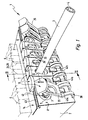
- eine perspektivische Teildarstellung einer mögli- chen ersten Bauform der erfindungsgemäßen fluid- technischen Vorrichtung, wobei der Übersichtlich- keit wegen nur einer der möglichen mehreren an- schließbaren Fluidschläuche abgebildet ist,
Figur 2- die Anordnung aus
Figur 1 bei vom Anschlusskörper komplett weggeschwenkten Halteschiebern, Figur 3- einen Schnitt durch die Anordnung aus
Figur 1 gemäß Schnittlinie III-III, wobei der Halteschieber bei Einnahme der Haltestellung gezeigt ist, Figur 4- die in
Figur 3 Figur 5- einen Schnitt durch die Anordnung aus
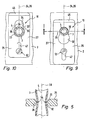
Figur 1 im Bereich einer Anschlusseinrichtung gemäß Schnittli- nie V-V ausFiguren 1 und9 , wobei eine mögliche Verformung des festgeklemmten Fluidschlauches er- sichtlich ist, - Figur 6
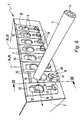
- eine perspektivische Teildarstellung einer modifi- zierten Bauform der fluidtechnischen Vorrichtung, wobei wiederum nur einer von mehreren anschließba- ren Fluidschläuchen gezeigt ist,
Figur 7- die Anordnung aus
Figur 6 im Schnitt gemäß Schnitt- linie VII-VII und im Bereich des Fluidkanals des Anschlusskörpers, teilweise aufgebrochen, das Ganze unmittelbar vor dem Festziehen einer Spannschraube, Figur 8- die
Anordnung aus Figur 7 bei in der Freigabestel- lung befindlichem Halteschieber und - Figuren 9 und 10
- Schnitte durch die
Anordnungen aus Figuren 7 und 8 gemäß Schnittlinie IX-IX und X-X.
- FIG. 1
- a partial perspective view of a possible first design of the fluidic device according to the invention, wherein the clarity is shown because of only one of the possible several connectable fluid hoses,
- FIG. 2
- the arrangement
FIG. 1 with holding slides completely pivoted away from the connection body, - FIG. 3
- a section through the arrangement
FIG. 1 according to section line III-III, wherein the retaining slide is shown on receipt of the holding position, - FIG. 4
- in the
FIG. 3 shown arrangement with pivoted away from the connection body retaining slide at the moment of insertion of the fluid to be connected hose, which is indicated by arrows, the subsequent movement of the retaining slide, - FIG. 5
- a section through the arrangement
FIG. 1 in the area of a connection device according to section line VVFIGS. 1 and9 wherein a possible deformation of the clamped fluid tube is evident, - FIG. 6
- 2 shows a partial perspective view of a modified design of the fluid power device, wherein in turn only one of a plurality of connectable fluid tubes is shown,
- FIG. 7
- the arrangement
FIG. 6 in section according to section VII-VII and in the region of the fluid channel of the connection body, partially broken, the whole immediately before tightening a clamping screw, - FIG. 8
- the arrangement
FIG. 7 with holding slide located in the release position and - FIGS. 9 and 10
- Cut through the arrangements
FIGS. 7 and 8 according to section line IX-IX and XX.
Die in
Bei dem Anschlusskörper 2 handelt es sich insbesondere um einen Ventilträger, der mit einem oder mehreren zur Steuerung von Fluidströmen geeigneten Ventilen 6 bestückbar oder bestückt ist. Die Ventile 6 sind elektrisch aktivierbar, entweder direkt oder indirekt mittels Vorsteuerstufen. In der Zeichnung sind sie nur in
Der Anschlusskörper 2 hat insbesondere eine block- oder plattenförmige Gestalt. Abweichende Formgebungen sind jedoch ebenfalls möglich.The
Bei den mit je einem Fluidschlauch 3 verbindbaren Fluidkanälen 5 des Ausführungsbeispiels handelt es sich um Arbeitskanäle, über die die Zufuhr und Abfuhr von Druckmedium zu beziehungsweise von einem nicht dargestellten Verbraucher stattfindet, beispielsweise ein mittels Fluidkraft betätigbarer Antrieb. Die Fluidkanäle 5 münden jeweils mit einer Anschlussöffnung 7 zu einer im Folgenden als Anschlussfläche 8 bezeichneten Außenfläche des Anschlusskörpers 2 aus, wobei der anzuschließende Fluidschlauch 3 durch die Anschlussöffnung 7 hindurch in den sich daran anschließenden Kanalendabschnitt 12 des Fluidkanals 5 gemäß Pfeil 13 einsteckbar ist. Der Fluidschlauch 3 stellt dann die Fluidverbindung zwischen dem betreffenden Fluidkanal 5 und dem externen Verbraucher her.The connectable to each
Die Fluidkanäle 5 verlaufen im Innern des Anschlusskörpers 2 und münden mit ihren den Anschlussöffnungen 7 entgegengesetzten Enden zu einer Bestückungsfläche 14 aus, an der die Ventile 6 installiert sind. Dort kommunizieren sie mit Kanälen der Ventile 6.The
In nicht näher dargestellter Weise ist der Anschlusskörper 2 in der Regel noch von mindestens einem Speisekanal und mindestens einem Abführkanal durchsetzt, über die eine zentrale Einspeisung und Abfuhr des Druckmediums erfolgt. Diese Kanäle münden so zu den Bestückungsflächen 14, dass sie mit sämtlichen Ventilen 6 kommunizieren.In a manner not shown in detail, the connecting
Bei einer nicht dargestellten Ausführungsform sind die Ventile 6 in den Anschlusskörper 2 integriert. Der Anschlusskörper 2 kann insbesondere ein unmittelbarer Bestandteil eines oder mehrerer Ventile sein, indem er beispielsweise, gemäß einer nicht dargestellten Bauform, ein Ventilgehäuse bildet.In one embodiment, not shown, the valves 6 are integrated into the
Abweichend von der abgebildeten Mehrfachausstattung mit zum Anschluss eines Fluidschlauches 3 geeigneten Anschlussöffnungen 7, kann der Anschlusskörper 2 auch über nur eine einzige solche Anschlussöffnung 7 verfügen.Deviating from the illustrated multiple equipment with suitable for connecting a
Enthält der Anschlusskörper 2 eine Mehrzahl von Anschlussöffnungen 7, sind diese zweckmäßigerweise in einer durch einen Doppelpfeil bei 15 angedeuteten Aufreihungsrichtung aufeinanderfolgend angeordnet. Die Aufreihungsrichtung 15 kann insbesondere mit der Längsrichtung des Anschlusskörpers 2 zusammenfallen.If the
Bei dem Anschlusskörper 2 kann es sich um einen in Längsrichtung ununterbrochenen einheitlichen Körper handeln, oder aber um ein segmentiertes Gebilde. Die einzelnen Segmente können jeweils mindestens eine der Anschlussöffnungen 7 aufweisen und sind in der Aufreihungsrichtung 15 unter Bildung einer Baugruppe insbesondere lösbar aneinander angesetzt.The
Die anschließbaren Fluidschläuche 3 sind aufgrund ihrer Elastizität leicht biegbar. Sie können auch problemlos mit einem geeigneten Schneidwerkzeug auf die jeweils gewünschte Länge abgelängt werden. Es handelt sich um Kunststoffschläuche, bevorzugt aus Polyurethanmaterial.The
Jeder Anschlussöffnung 7 ist eine Anschlusseinrichtung 16 zur lösbaren, klemmenden Fixierung eines beliebigen Fluidschlauches 3 zugeordnet. Die Anschlusseinrichtung 16 ist zur Gänze Bestandteil des Anschlusskörpers 2. Am Fluidschlauch 3 finden sich keine Komponenten der Anschlusseinrichtung 16.Each
Die Anschlusseinrichtungen 16 ermöglichen das Anschließen des zugeordneten Fluidschlauches 3 im Rahmen einer einfachen Steckverbindung. Um die Fluidverbindung zu lösen, wird der Fluidschlauch 3 nach vorheriger Manipulation an der zugeordneten Anschlusseinrichtung 16 einfach herausgezogen.The
Anhand insbesondere der
Das Anschlussende 17 des eingesteckten Fluidschlauches 3 ist in radialer Richtung bezüglich des Anschlusskörpers 2 abgestützt. Die Abstützfunktion kann der Anschlusskörper 2 unmittelbar selbst übernehmen, wenn der Kanalendabschnitt 12 einen dem nominalen Außendurchmesser des Fluidschlauches 3 entsprechenden Innendurchmesser aufweist.The
Abweichend hiervon hat der Kanalendabschnitt 12 bei den Ausführungsbeispielen einen größeren Querschnitt als der Fluidschlauch 3. Den Zwischenraum füllt eine in den Kanalendabschnitt 12 eingesetzte und bevorzugt eingepresste Zentrierhülse 22 aus. Deren Innendurchmesser entspricht im Wesentlichen dem nominalen Außendurchmesser des Fluidschlauches 3, wobei ersichtlich ist, dass man durch Verwendung von Zentrierhülsen 22 unterschiedlicher Innendurchmesser eine Anpassung des Anschlusskörpers 2 an Fluidschläuche 3 unterschiedlicher nominaler Außendurchmesser vornehmen kann.Notwithstanding this, the
Die Zentrierhülse 22 kann eine Metallhülse sein, sie besteht vorzugsweise jedoch aus Kunststoffmaterial.The centering
In dem Kanalendabschnitt 12 befindet sich des Weiteren ein Dichtungsring 23. Er ist so angeordnet, dass er vom Anschlussende 17 des eingesteckten Fluidschlauches 3 durchsetzt wird und an dessen Außenumfang dichtend anliegt. Gleichzeitig stützt er sich dichtend an der Begrenzungsfläche des Kanalendabschnittes 12 ab. Dadurch ist ein Entweichen von Druckmedium am Fluidschlauch 3 vorbei verhindert.In the
Der Dichtungsring 23 ist zweckmäßigerweise mit bezüglich der Zentrierhülse 22 koaxialer Anordnung axial zwischen der Zentrierhülse 22 und der Anschlagfläche 18 platziert. Auf diese Weise wird er durch die Zentrierhülse 22 in dem Kanalendabschnitt 12 verliersicher gehalten.The sealing
Jede Anschlusseinrichtung 16 enthält einen relativ zum Anschlusskörper 2 in Richtung einer Betätigungsachse 24 verschiebbaren Halteschieber 25. Der Halteschieber 25 ist insbesondere ein längliches Gebilde, wobei seine Längsachse 26 vorzugsweise mit der Betätigungsachse 24 zusammenfällt.Each
Der Halteschieber 25 ist der Anschlussfläche 8 vorgelagert. Vor jeder Anschlussöffnung 7 erstreckt sich ein Halteschieber 25, der die zugeordnete Anschlussöffnung 7 stellungsabhängig in mehr oder weniger großem Maße überdeckt.The retaining
Der Halteschieber ist zweckmäßigerweise als Flachschieber ausgeführt. Er verfügt über ein im Wesentlichen plattenförmiges Schieber-Hauptelement 27, das derart vor der Anschlussfläche 8 angeordnet oder positionierbar ist, dass seine Hauptausdehnungsebene rechtwinkelig zur Längsachse 28 der zugeordneten Anschlussöffnung 7 orientiert ist. Diese Längsachse 28 ist gleichzeitig die Längsachse des Kanalendabschnittes 12.The retaining slide is expediently designed as a flat slide. It has a substantially plate-shaped slider
Der Zustand, den der Halteschieber 25 einnimmt, wenn er so positioniert ist, dass die Betätigungsachse 24 rechtwinkelig zu der Längsachse 28 verläuft, sei im Folgenden als Umschaltzustand bezeichnet. Bei Einnahme dieses Umschaltzustandes kann der Halteschieber 25 zwischen einer in
Die Haltestellung ist auch noch in
Der Halteschieber 25 ist im Bereich seines Schieber-Hauptelements 27 von einer Durchtrittsöffnung 32 durchsetzt. Diese hat einen länglichen Querschnitt und erstreckt sich längs der. Längsachse 26. Sie hat einen sich über ihre Länge hinweg verändernden Querschnitt mit einem Durchsteckabschnitt 33 größerer Breite und einem sich daran in Richtung der Betätigungsachse 24 anschließenden Halteabschnitt 34 geringerer Breite. Am einfachsten lässt sich diese Kontur durch eine schlüssellochförmige Gestaltung der Durchtrittsöffnung 32 erreichen, wie sie aus
Die beiden stirnseitigen Endabschnitte der länglichen Durchtrittsöffnung 32 sind zweckmäßigerweise konkav gewölbt. Die Übergangsbereiche 35 zwischen den beiden Abschnitten 33, 34 der Durchtrittsöffnung 32 sind insbesondere abgerundet.The two end-side end portions of the
Die rechtwinkelig zu der Betätigungsachse 24 gemessenen Breitenabmessungen des Durchsteckabschnittes 33 sind größer als der nominale Außendurchmesser des Fluidschlauches 3. Unter dem nominalen Außendurchmesser des Fluidschlauches 3 ist der im unverformten Zustand gemessene Außendurchmesser zu verstehen.The width dimensions of the push-through
Durch diese gegenseitige maßliche Abstimmung ist gewährleistet, dass der Fluidschlauch 3 ohne Behinderung im Bereich des Durchsteckabschnittes 33 durch die Durchtrittsöffnung 32 hindurchsteckbar ist.By this mutual dimensional adjustment is ensured that the
Im Gegensatz dazu ist die entsprechend gemessene Breite des Halteabschnittes 34 geringer als der nominale Außendurchmesser des Fluidschlauches 3. Wenn der Fluidschlauch 3 die Durchtrittsöffnung 32 im Bereich des Halteabschnittes 34 durchsetzt, erfährt er durch die den Halteabschnitt 34 seitlich begrenzenden Schieberabschnitte 36 eine radiale Beaufschlagung, die dazu führt, dass die Schlauchwandung des Fluidschlauches 3, insbesondere in radialer Richtung, elastisch verformt wird. Aufgrund der sich hierbei aufbauenden Rückstellkräfte ergibt sich eine klemmende Fixierung des Fluidschlauches 3 in dem Halteabschnitt 34.In contrast, the corresponding measured width of the holding
Gemäß der Schnittdarstellung in
Bei dem Ausführungsbeispiel der
Nach diesem Einstecken wird manuell eine Betätigungskraft FB auf den Halteschieber 25 ausgeübt. Dadurch wird die Durchtrittsöffnung 32 mit ihrem Halteabschnitt 34 quer zur Schlauch-Längsrichtung auf den Fluidschlauch 3 aufgeschoben. Dies ergibt die schon erwähnte Haltestellung, in der der Fluidschlauch 3 durch den Halteschieber 25 derart klemmend am Außenumfang beaufschlagt ist, dass er nicht mehr herausgezogen werden kann.After this insertion, an actuating force F B is manually exerted on the retaining
Um den Fluidschlauch 3 wieder zu lösen, ist der Halteschieber 25 lediglich in der entgegengesetzten Richtung zu verlagern, bis er neuerlich die Freigabestellung einnimmt, die das Herausziehen des Fluidschlauches 3 ermöglicht.In order to release the
Diese Funktionsbeschreibung gilt entsprechend für das Ausführungsbeispiel der
Allen Ausführungsbeispielen ist gemeinsam, dass der angeschlossene Fluidschlauch 3 jeweils unmittelbar selbst durch die Durchtrittsöffnung 32 des Halteschiebers 25 hindurch in die Anschlussöffnung 7 des Anschlusskörpers 2 eingesteckt ist. Die Schnittstelle der Verbindungsmaßnahmen liegt also unmittelbar am Fluidschlauch, der mithin keiner vorherigen Bestückung mit irgendwelchen zusätzlichen Anschlusssteckern bedarf.All embodiments have in common that the connected
Die Bauform mit einer zusätzlich zu der linearen Verschiebemöglichkeit vorhandenen Schwenkmöglichkeit 37 eignet sich insbesondere für eine kostengünstige Realisierungsform mit aus Kunststoffmaterial bestehendem Halteschieber 25, der einstückig an den insoweit ebenfalls aus Kunststoffmaterial bestehenden Anschlusskörper 2 angeformt ist. Das gesamte Bauteil kann hier kostengünstig in Kunststoff-Spritzgießtechnik hergestellt werden, ohne dass die Notwendigkeit bestünde, die Halteschieber 25 nachträglich mechanisch am Anschlusskörper 2 zu fixieren.The design with an addition to the linear displacement possibility existing pivoting
Konkret sieht das Ausführungsbeispiel der
Der Gelenkabschnitt 38 befindet sich zweckmäßigerweise am einen der beiden längs orientierten Endabschnitte des Halteschiebers 25. Über diesen Gelenkabschnitt 38 kann bei Bedarf die schon erwähnte einstückige Verbindung zwischen dem Halteschieber 25 und dem Anschlusskörper 2 hergestellt sein.The
Bevorzugt ist der Halteschieber 25, insbesondere an seinem dem Gelenkabschnitt 38 entgegengesetzten Endabschnitt, mit einer ersten Hakenstruktur 42 ausgestattet. Selbige weist in Richtung des Gelenkabschnitts 38. Am Anschlusskörper 2 ist eine komplementäre erste Verankerungsstruktur 43 ausgebildet, mit der die erste Hakenstruktur 42 bei herangeschwenktem Halteschieber 25 in Verhakungseingriff bringbar ist.Preferably, the retaining
Der Gelenkabschnitt 38 ist zweckmäßigerweise so ausgebildet, dass er den Halteschieber 25 normalerweise in einer Position hält, die es der ersten Hakenstruktur 32 nicht ermöglicht, allein durch Verschwenken 37 in oder außer Eingriff mit der ersten Verankerungsstruktur 43 zu gelangen. Um diese Maßnahmen zu ergreifen, bedarf es einer der Schwenkbewegung 37 überlagerten Zugbeaufschlagung des Halteschiebers 25 in Richtung seiner Längsachse 26 und hierbei weg von dem Gelenkabschnitt 38. Der Gelenkabschnitt 38 wird hierbei elastisch gedehnt, und die erste Hakenstruktur 42 kann über die erste Verankerungsstruktur 43 hinwegbewegt werden. Beim anschließenden Loslassen des Halteschiebers 25 wird die erste Hakenstruktur 42 durch den Gelenkabschnitt 38 auf Zug beaufschlagt, im Sinne eines Eingreifens in die erste Verankerungsstruktur 43.The
Dieser Bewegungsablauf ist in
Schon während dieses Bewegungsablaufes 44 kann der Fluidschlauch 3 ein Stückweit durch die Durchtrittsöffnung 32 hindurchgesteckt sein, wie dies in
Die durch die elastische Verformung hervorgerufene Zugkraft seitens des Gelenkabschnittes 38 reicht normalerweise nicht aus, um den Halteschieber 25 bei eingestecktem Fluidschlauch 3 in die Haltestellung zu verlagern. Hierzu wird neuerlich die schon erwähnte Betätigungskraft FB aufgebracht. Gleichzeitig wird hierbei der Verhakungseingriff zwischen den beiden Strukturen 42, 43 vertieft.The induced by the elastic deformation tensile force on the part of the
Die erste Hakenstruktur 42 befindet sich zweckmäßigerweise an einem dem Gelenkabschnitt 38 entgegengesetzten Kopfabschnitt 45 des Halteschiebers 25, der gleichzeitig einen Betätigungsabschnitt bildet, der zur manuellen Einwirkung zum Zwecke der Handhabung des Halteschiebers 25 vorgesehen ist.The
Der Gelenkabschnitt 38 hat zweckmäßigerweise eine gebogene oder bügelförmige Struktur. Beim Ausführungsbeispiel setzt er sich aus zwei nebeneinanderliegenden federelastischen Gelenkbügeln 46 zusammen, die funktionell mit einem Filmscharnier vergleichbar sind.The
Aufgrund der Elastizität des Gelenkabschnittes 38 kann unter Umständen allein durch den Eingriff von erster Hakenstruktur 42 und erster Verankerungsstruktur 43 kein ausreichend fester Halt des Halteschiebers 25 in der Haltestellung gewährleistet werden. Es ist daher empfehlenswert, an in Richtung der Betätigungsachse 24 beabstandeter Stelle eine zweite Hakenstruktur 42a vorzustehen, die in vergleichbarer Weise wie bei den beiden ersten Strukturen 42, 43 mit einer zweiten Verankerungsstruktur 43a in Verhakungseingriff bringbar ist.Due to the elasticity of the
Exemplarisch ist die zweite Hakenstruktur 43a am Anschlusskörper 2 angeordnet, und die zweite Verankerungsstruktur 43a befindet sich am Halteschieber 25, wenngleich auch eine umgekehrte Anbringungsweise möglich ist, wie dies im Übrigen auch für die beiden ersten Strukturen 42, 43 gilt.By way of example, the
Bevorzugt ist die zweite Verankerungsstruktur 43a von dem zwischen den beiden Gelenkbügeln 46 verlaufenden Randabschnitt des Halteschiebers 25 gebildet. Die zweite Hakenstruktur 42a ragt zweckmäßigerweise von der Anschlussfläche 8 weg und zwischen den beiden Gelenkbügeln 46 hindurch, um den vorgenannten Randabschnitt des Halteschiebers 25 hintergreifen zu können.The
Auf diese Weise ergibt sich eine Zwei-Punkt-Verankerung des in Haltestellung befindlichen Halteschiebers 25, sodass er sich auch hohen, auf den Fluidschlauch 3 einwirkenden Zugkräften widersetzen kann.In this way, there is a two-point anchorage of the retaining
Bei dem Ausführungsbeispiel der
Bei gelöster, jedoch weiterhin in den Anschlusskörper 2 eingeschraubter Spannschraube 48 kann der Halteschieber 25 zwischen der Haltestellung und der Freigabestellung verschoben werden. Jede dieser Stellungen, insbesondere aber die Haltestellung, kann dadurch gesichert werden, dass die Spannschraube 48 festgezogen und dadurch der Halteschieber 25 zwischen dem Schraubenkopf 52 und dem Anschlusskörper 2 eingespannt wird. Ein versehentliches Lösen der Haltestellung wird dadurch vermieden.When dissolved, but still screwed into the
Der Schraubenschaft 53 bildet bei gelöster Spannschraube 48 einen Bolzen, der als Führungselement mit den Flanken des Langloches 47 zusammenarbeiten kann. Insbesondere wenn, wie beim Ausführungsbeispiel, mehrere Halteschieber 25 mit zueinander parallelen Längsachsen Seite an Seite nebeneinanderliegend angeordnet sind, kann sich die angestrebte Verschiebeführung aber auch schon durch den gegenseitigen Kontakt der jeweils benachbarten Halteschieber 25 im Bereich ihrer Längsränder einstellen.The
Der Schraubenschaft 53 oder alternativ ein anderer, das Langloch 47 durchsetzender Bolzen kann auch einen Anschlag bilden, der durch Zusammenwirken mit den das Langloch stirnseitig begrenzenden Schieberabschnitten den Verschiebeweg für den Halteschieber 25 begrenzt.The
Auch an dem bezüglich des Anschlusskörpers 2 separat ausgebildeten Halteschieber 25 befindet sich einenends zweckmäßigerweise ein manuell beaufschlagbarer Betätigungsabschnitt 45 zur Einleitung der Betätigungskraft für die Verschiebebewegung des Halteschiebers 25.Also at the respect to the connecting
Aus
Claims (18)
- Fluidic device with at least one connection body (2), through which passes at least one fluid passage (5) which leads out via a connection orifice (7) to the outer surface of the connection body (2), and with at least one flexible fluid hose (3) with elastomeric properties, which is or may be connected by means of a connection device (16), as part of a plug-in connection, to the fluid passage or passages (5), wherein the connection device (16) contains a holding slide (25), slidably mounted or mountable on the connection body (2) in the direction of an axis of actuation (24) running at right-angles to the longitudinal axis (28) of the connection orifice (7), through which runs a through passage (32) which has an insertion section (33) and a holding section (34), narrower than the former and adjoining it in the direction of the axis of actuation (24), wherein the holding slide (25) may be positioned either in a release position, in which the insertion section (33) is flush with the connection orifice (7), or in a holding position in which the holding section (34) is aligned with the connection orifice (7), characterised in that the connected fluid hose (3) is inserted directly itself through the through passage (32) of the holding slide (25) into the connection orifice (7) of the connection body (2), wherein the width of the through passage (32) in the area of the insertion section (33) is greater, and in the area of the holding section (34) is less than the nominal outside diameter of the fluid hose (3), in such a way that the fluid hose (3) in the release position of the holding slide (25) may be inserted unimpeded through the through passage (32) into the connection orifice (7) and removed from it, and in the holding position of the holding slide (25) is held, with deformation of its hose wall, clamped by the slide sections (36) bounding the side of the holding section (34).
- Device according to claim 1, characterised in that the through passage (32) is made in the manner of a keyhole.
- Device according to claim 1 or 2, characterised in that the slide sections (36) bounding the holding section (34) have a cross-section contour tapering towards the holding section (34) and are expediently tapered in a blade-like manner.
- Device according to any of claims 1 to 3, characterised in that the holding slide (25) has at least one oblong hole (47) extending in the direction of the axis of actuation (24), through which passes a pin (53) fixed to the connection body (2).
- Device according to claim 4, characterised in that the pin (53) forms a stop which, through cooperation with the slide sections bounding the end of the oblong hole (47), defines the sliding path for the holding slide (25).
- Device according to claim 4 or 5, characterised in that the pin is formed by the shank (53) of a clamping bolt (48), screwed into the connection body (2), the screw head (52) of which forms a clamping element, by means of which the holding slide (25) may be clamped releasably to the connection body (2) to secure its position.
- Device according to any of claims 1 to 6, characterised in that the holding slide (25) is a separate component from the connection body (2).
- Device according to any of claims 1 to 7, characterised in that the holding slide (25) is made of metal.
- Device according to any of claims 1 to 8, characterised in that the holding slide (25) is fixed movably to the connection body (2) via an elastically deformable hinge section (38) in such a way that it may be displaced in the direction of its longitudinal axis (26) and expediently may also be swivelled towards and away from the connection body (2), wherein the hinge section (38) is expediently comprised of at least one spring-elastic deformable hinged bracket (46).
- Device according to claim 9, characterised in that the holding slide (25), in the position in which it is swivelled on to the connection body (2), is adjustable by shifting in the direction of its longitudinal axis (26) coinciding with the axis of actuation (24) between a released position allowing swivelling, and a locked position which prevents swivelling.
- Device according to claim 10, characterised in that there is provided on the holding slide (25) and/or on the connection body (2) a hook structure (42, 42a) which is able to engage behind an anchoring structure (43, 43a) formed on the respective other element (2, 25), wherein the bringing into or out of engagement between the hook structure (42, 42a) and the anchoring structure (43, 43a) may be effected by sliding the holding slide (25) swivelled on to the connection body (2) in the direction of the axis of actuation (24).
- Device according to claim 11, characterised in that the holding slide (25) is pressure-loaded by the hinge section (38) in such a way that the hook structure or structures (42, 42a) is or are biased in the direction of engagement with the anchoring structure (43, 43a).
- Device according to any of claims 9 to 12, characterised in that the holding slide (25) is joined integrally with the connection body (2) via the hinge section (38).
- Device according to any of claims 9 to 13, characterised in that the holding slide (25), the hinge section (38) and the area of the connection body (2) joined to the hinge section (38) are made of plastic material.
- Device according to any of claims 1 to 14, characterised in that a centring sleeve (22) encompassing the inserted fluid hose (3) is inserted and in particular pressed into the passage end section (12) of the fluid passage (5) adjoining the connection orifice (7).
- Device according to any of claims 1 to 15, characterised in that there is provided in the passage end section (12) of the fluid passage (5) adjoining the connection orifice (7) a seal ring (23) encompassing the inserted fluid hose (3) and which is expediently located axially between the centring sleeve (22) and a boundary surface (18) of the fluid passage (5) lying opposite and axially inwards of the former.
- Device according to any of claims 1 to 16, characterised in that there are provided on the connection body (2) in a direction of lining-up (15) several consecutive connection orifices (7), each assigned a connection device (16) with a holding slide (25), wherein the holding slides (25) are mounted next to one another on their long sides with parallel longitudinal axes (26), and wherein expediently adjacent holding slides (25) abut one another with their long-side edge sections, under mutual guidance.
- Device according to any of claims 1 to 17, characterised in that the connection body (2) is formed by a valve carrier equipped with at least one valve (6).
Applications Claiming Priority (2)
| Application Number | Priority Date | Filing Date | Title |
|---|---|---|---|
| DE202006011624U DE202006011624U1 (en) | 2006-07-29 | 2006-07-29 | Fluid device e.g. for motor vehicle brake system, has retaining section formed within depressed opening of each slide gate valve and has width smaller than width of passing through section within opening and nominal diameter of fluid hose |
| PCT/EP2007/001834 WO2008014829A1 (en) | 2006-07-29 | 2007-03-03 | Hydraulically operated device |
Publications (2)
| Publication Number | Publication Date |
|---|---|
| EP2047110A1 EP2047110A1 (en) | 2009-04-15 |
| EP2047110B1 true EP2047110B1 (en) | 2011-08-03 |
Family
ID=37085672
Family Applications (1)
| Application Number | Title | Priority Date | Filing Date |
|---|---|---|---|
| EP07723027A Not-in-force EP2047110B1 (en) | 2006-07-29 | 2007-03-03 | Hydraulically operated device |
Country Status (5)
| Country | Link |
|---|---|
| US (1) | US8075022B2 (en) |
| EP (1) | EP2047110B1 (en) |
| CN (1) | CN101495763B (en) |
| DE (1) | DE202006011624U1 (en) |
| WO (1) | WO2008014829A1 (en) |
Families Citing this family (9)
| Publication number | Priority date | Publication date | Assignee | Title |
|---|---|---|---|---|
| DE102007023160A1 (en) * | 2007-05-16 | 2008-11-20 | Robert Bosch Gmbh | Hydraulic and / or pneumatic device and hydraulic and / or pneumatic system |
| DE502007002698D1 (en) * | 2007-11-24 | 2010-03-11 | Festo Ag & Co Kg | Control cabinet with internal valve arrangement |
| US9188571B2 (en) * | 2011-08-26 | 2015-11-17 | Waters Technologies Corporation | Chromatography apparatus having diffusion bonded coupler |
| DE102015005265A1 (en) * | 2015-04-11 | 2016-10-13 | Testo Ag | Probe holder for a measuring instrument |
| US10292308B2 (en) * | 2015-07-28 | 2019-05-14 | Futurewei Technologies, Inc. | Fluid coupling mating apparatus and method |
| EP3388728B1 (en) * | 2017-04-12 | 2020-02-12 | Mahle International GmbH | Pipe connector for connecting two pipe sections |
| US10792639B2 (en) * | 2017-04-26 | 2020-10-06 | Massachusetts Institute Of Technology | Reconfigurable chemical synthesis systems and methods |
| JP6953472B2 (en) * | 2019-04-26 | 2021-10-27 | Ckd株式会社 | Manifold |
| US20230015663A1 (en) * | 2021-07-12 | 2023-01-19 | Sanctuary Cognitive Systems Corporation | Hydraulic fitting, and applications thereof in robot systems |
Family Cites Families (18)
| Publication number | Priority date | Publication date | Assignee | Title |
|---|---|---|---|---|
| US2839073A (en) * | 1956-03-21 | 1958-06-17 | Kestral Corp | Valve for inflatable articles |
| US3758138A (en) * | 1971-10-21 | 1973-09-11 | R Roseman | Tube connection for fluid handling apparatus |
| US3929356A (en) * | 1974-11-13 | 1975-12-30 | Gen Motors Corp | Tube to block mounting assembly |
| DE2849133A1 (en) * | 1978-11-13 | 1980-05-29 | Voss Armaturen | Brake pipe union to valve housing - comprises plug held in bore by external tangential locking devices |
| US4453747A (en) * | 1982-06-01 | 1984-06-12 | Bimba Charles W | Connector system for flexible tubing |
| US4600221A (en) * | 1985-09-30 | 1986-07-15 | Bimba Charles W | Connection system for flexible tubing |
| DE3705136A1 (en) * | 1987-02-18 | 1988-09-01 | Bosch Siemens Hausgeraete | Closure safeguard for a run-off hose of a washing machine or dishwasher |
| US5040831A (en) * | 1990-01-12 | 1991-08-20 | Phil Lewis | Non threaded pipe connector system |
| DE4014666C1 (en) * | 1990-05-08 | 1991-11-21 | Mercedes-Benz Aktiengesellschaft, 7000 Stuttgart, De | |
| DE4209000C1 (en) | 1992-03-20 | 1993-05-27 | Mercedes-Benz Aktiengesellschaft, 7000 Stuttgart, De | Connector for fluid carrying pipes - has coaxial ring groove with sealing ring in each opening in the housing and has tensioning device with clamping lugs |
| US5343889A (en) * | 1992-09-21 | 1994-09-06 | Jaw Horng Chang | Nozzle for inflatable objects |
| US5453098A (en) * | 1994-05-09 | 1995-09-26 | Imed Corporation | Two step IV fluid flow stop |
| BR9600812A (en) * | 1996-02-26 | 1997-12-23 | Tampas Click Ltda | Quick connector |
| JP3508381B2 (en) * | 1996-04-26 | 2004-03-22 | 東海ゴム工業株式会社 | One-touch connection device for focusing hose |
| DE19755743C1 (en) | 1997-12-16 | 1999-03-25 | Festo Ag & Co | Connector for pressure hoses |
| US6222128B1 (en) * | 1999-04-20 | 2001-04-24 | Arlington Industries, Inc. | Cable support |
| FR2844333B1 (en) * | 2002-09-11 | 2004-11-26 | Bosch Gmbh Robert | DEVICE FOR QUICK CONNECTION OF MALE AND FEMALE ORGANS AND RESERVOIR ASSEMBLY FOR BRAKE FLUID THEREOF |
| US8336736B2 (en) * | 2008-05-15 | 2012-12-25 | Schroeder Industries, Inc. | Flow control and manifold assembly |
-
2006
- 2006-07-29 DE DE202006011624U patent/DE202006011624U1/en not_active Expired - Lifetime
-
2007
- 2007-03-03 US US12/309,700 patent/US8075022B2/en not_active Expired - Fee Related
- 2007-03-03 WO PCT/EP2007/001834 patent/WO2008014829A1/en active Application Filing
- 2007-03-03 EP EP07723027A patent/EP2047110B1/en not_active Not-in-force
- 2007-03-03 CN CN200780028450XA patent/CN101495763B/en not_active Expired - Fee Related
Also Published As
| Publication number | Publication date |
|---|---|
| EP2047110A1 (en) | 2009-04-15 |
| CN101495763A (en) | 2009-07-29 |
| DE202006011624U1 (en) | 2006-09-28 |
| US20090189390A1 (en) | 2009-07-30 |
| CN101495763B (en) | 2012-06-13 |
| US8075022B2 (en) | 2011-12-13 |
| WO2008014829A1 (en) | 2008-02-07 |
Similar Documents
| Publication | Publication Date | Title |
|---|---|---|
| EP2047110B1 (en) | Hydraulically operated device | |
| EP1637790B1 (en) | Connecting device for fluid conduits | |
| DE4327825C2 (en) | Throttle check element | |
| EP2427683B1 (en) | Coupling piece | |
| EP1250547A1 (en) | Connection device for a fluid line | |
| DE102010037545A1 (en) | Pneumatic coupling module, in particular for a zero-point clamping system for a machine tool | |
| DE1085721B (en) | Clamp connection | |
| DE102005058161B4 (en) | Quick release for the installation area | |
| DE3923579A1 (en) | Connector for plastics pipes - is in one piece with widening bore socket for holding ring and sealing ring | |
| EP3730705A1 (en) | Sanitary valve | |
| DE19725999C1 (en) | Plug connection device and fluid distribution device equipped with one or more plug connection devices | |
| EP2102509B1 (en) | Tie-rod and module arrangement clamped together thereto | |
| EP2623841B1 (en) | Partition piece for a fluid channel and fluids device with such a partition piece | |
| EP1304522B1 (en) | Vent coupling with force compensation at the operating sleeve | |
| EP3230648B1 (en) | Prefabricated valve assembly, assembly method for assembling the valve assembly, receiving part of a dry coupling for fluid equipped with the valve assembly, and dry coupling for fluid which has the receiving part | |
| DE3628543A1 (en) | CONNECTOR | |
| WO2008138678A1 (en) | Hydraulic and/or pneumatic device and hydraulic and/or pneumatic system | |
| DE112017003127T5 (en) | speed control | |
| EP1745234B1 (en) | Hose clamping device | |
| DE3013235A1 (en) | Poppet valve for regulating the flow of a pressurized fluid | |
| EP1602831A1 (en) | Actuating device activated by fluid pressure | |
| DE19812044C1 (en) | Thread insert for pneumatic or hydraulic systems | |
| DE10058967A1 (en) | Pipe connector comprises sleeve made up of two rings with inwardly-facing teeth, clamping arms separated by longitudinal slits being attached to each ring and arms on one ring fitting between arms on other | |
| DE3901466C2 (en) | ||
| EP3101318A1 (en) | Valve module |
Legal Events
| Date | Code | Title | Description |
|---|---|---|---|
| PUAI | Public reference made under article 153(3) epc to a published international application that has entered the european phase |
Free format text: ORIGINAL CODE: 0009012 |
|
| 17P | Request for examination filed |
Effective date: 20081205 |
|
| AK | Designated contracting states |
Kind code of ref document: A1 Designated state(s): AT BE BG CH CY CZ DE DK EE ES FI FR GB GR HU IE IS IT LI LT LU LV MC MT NL PL PT RO SE SI SK TR |
|
| AX | Request for extension of the european patent |
Extension state: AL BA HR MK RS |
|
| DAX | Request for extension of the european patent (deleted) | ||
| RBV | Designated contracting states (corrected) |
Designated state(s): CH DE FR GB IT LI |
|
| GRAP | Despatch of communication of intention to grant a patent |
Free format text: ORIGINAL CODE: EPIDOSNIGR1 |
|
| GRAS | Grant fee paid |
Free format text: ORIGINAL CODE: EPIDOSNIGR3 |
|
| GRAA | (expected) grant |
Free format text: ORIGINAL CODE: 0009210 |
|
| AK | Designated contracting states |
Kind code of ref document: B1 Designated state(s): CH DE FR GB IT LI |
|
| REG | Reference to a national code |
Ref country code: GB Ref legal event code: FG4D Free format text: NOT ENGLISH |
|
| REG | Reference to a national code |
Ref country code: CH Ref legal event code: NV Representative=s name: TROESCH SCHEIDEGGER WERNER AG Ref country code: CH Ref legal event code: EP |
|
| REG | Reference to a national code |
Ref country code: DE Ref legal event code: R096 Ref document number: 502007007857 Country of ref document: DE Effective date: 20111006 |
|
| PLBE | No opposition filed within time limit |
Free format text: ORIGINAL CODE: 0009261 |
|
| STAA | Information on the status of an ep patent application or granted ep patent |
Free format text: STATUS: NO OPPOSITION FILED WITHIN TIME LIMIT |
|
| 26N | No opposition filed |
Effective date: 20120504 |
|
| REG | Reference to a national code |
Ref country code: DE Ref legal event code: R097 Ref document number: 502007007857 Country of ref document: DE Effective date: 20120504 |
|
| REG | Reference to a national code |
Ref country code: FR Ref legal event code: PLFP Year of fee payment: 9 |
|
| PGFP | Annual fee paid to national office [announced via postgrant information from national office to epo] |
Ref country code: IT Payment date: 20150323 Year of fee payment: 9 |
|
| PGFP | Annual fee paid to national office [announced via postgrant information from national office to epo] |
Ref country code: FR Payment date: 20150319 Year of fee payment: 9 |
|
| PGFP | Annual fee paid to national office [announced via postgrant information from national office to epo] |
Ref country code: CH Payment date: 20160322 Year of fee payment: 10 |
|
| PGFP | Annual fee paid to national office [announced via postgrant information from national office to epo] |
Ref country code: GB Payment date: 20160309 Year of fee payment: 10 |
|
| REG | Reference to a national code |
Ref country code: FR Ref legal event code: ST Effective date: 20161130 |
|
| PG25 | Lapsed in a contracting state [announced via postgrant information from national office to epo] |
Ref country code: FR Free format text: LAPSE BECAUSE OF NON-PAYMENT OF DUE FEES Effective date: 20160331 |
|
| PG25 | Lapsed in a contracting state [announced via postgrant information from national office to epo] |
Ref country code: IT Free format text: LAPSE BECAUSE OF NON-PAYMENT OF DUE FEES Effective date: 20160303 |
|
| REG | Reference to a national code |
Ref country code: CH Ref legal event code: PL |
|
| GBPC | Gb: european patent ceased through non-payment of renewal fee |
Effective date: 20170303 |
|
| PG25 | Lapsed in a contracting state [announced via postgrant information from national office to epo] |
Ref country code: CH Free format text: LAPSE BECAUSE OF NON-PAYMENT OF DUE FEES Effective date: 20170331 Ref country code: GB Free format text: LAPSE BECAUSE OF NON-PAYMENT OF DUE FEES Effective date: 20170303 Ref country code: LI Free format text: LAPSE BECAUSE OF NON-PAYMENT OF DUE FEES Effective date: 20170331 |
|
| PGFP | Annual fee paid to national office [announced via postgrant information from national office to epo] |
Ref country code: DE Payment date: 20180301 Year of fee payment: 12 |
|
| REG | Reference to a national code |
Ref country code: DE Ref legal event code: R119 Ref document number: 502007007857 Country of ref document: DE |
|
| PG25 | Lapsed in a contracting state [announced via postgrant information from national office to epo] |
Ref country code: DE Free format text: LAPSE BECAUSE OF NON-PAYMENT OF DUE FEES Effective date: 20191001 |