EP2046478B1 - Filtereinheit mit einem konischen gewinde - Google Patents
Filtereinheit mit einem konischen gewinde Download PDFInfo
- Publication number
- EP2046478B1 EP2046478B1 EP07787441A EP07787441A EP2046478B1 EP 2046478 B1 EP2046478 B1 EP 2046478B1 EP 07787441 A EP07787441 A EP 07787441A EP 07787441 A EP07787441 A EP 07787441A EP 2046478 B1 EP2046478 B1 EP 2046478B1
- Authority
- EP
- European Patent Office
- Prior art keywords
- filter element
- housing
- thread
- threads
- filter
- Prior art date
- Legal status (The legal status is an assumption and is not a legal conclusion. Google has not performed a legal analysis and makes no representation as to the accuracy of the status listed.)
- Active
Links
Images


Classifications
-
- B—PERFORMING OPERATIONS; TRANSPORTING
- B01—PHYSICAL OR CHEMICAL PROCESSES OR APPARATUS IN GENERAL
- B01D—SEPARATION
- B01D46/00—Filters or filtering processes specially modified for separating dispersed particles from gases or vapours
-
- B—PERFORMING OPERATIONS; TRANSPORTING
- B01—PHYSICAL OR CHEMICAL PROCESSES OR APPARATUS IN GENERAL
- B01D—SEPARATION
- B01D46/00—Filters or filtering processes specially modified for separating dispersed particles from gases or vapours
- B01D46/24—Particle separators, e.g. dust precipitators, using rigid hollow filter bodies
- B01D46/2403—Particle separators, e.g. dust precipitators, using rigid hollow filter bodies characterised by the physical shape or structure of the filtering element
- B01D46/2411—Filter cartridges
- B01D46/2414—End caps including additional functions or special forms
-
- B—PERFORMING OPERATIONS; TRANSPORTING
- B01—PHYSICAL OR CHEMICAL PROCESSES OR APPARATUS IN GENERAL
- B01D—SEPARATION
- B01D46/00—Filters or filtering processes specially modified for separating dispersed particles from gases or vapours
- B01D46/24—Particle separators, e.g. dust precipitators, using rigid hollow filter bodies
-
- B—PERFORMING OPERATIONS; TRANSPORTING
- B01—PHYSICAL OR CHEMICAL PROCESSES OR APPARATUS IN GENERAL
- B01D—SEPARATION
- B01D2265/00—Casings, housings or mounting for filters specially adapted for separating dispersed particles from gases or vapours
- B01D2265/02—Non-permanent measures for connecting different parts of the filter
- B01D2265/021—Anti-rotational means
-
- B—PERFORMING OPERATIONS; TRANSPORTING
- B01—PHYSICAL OR CHEMICAL PROCESSES OR APPARATUS IN GENERAL
- B01D—SEPARATION
- B01D2265/00—Casings, housings or mounting for filters specially adapted for separating dispersed particles from gases or vapours
- B01D2265/02—Non-permanent measures for connecting different parts of the filter
- B01D2265/029—Special screwing connections, threaded sections
Definitions
- the invention relates to a filter unit having a housing and a cylindrical filter element which can be inserted therein and which is connected at the end to an end disk.
- Filter units which comprise with their housing a substantially cylindrical filter element which is accessible after removal of a lid and can be replaced.
- plug and screw connections are known for attachment of the filter element at the bottom of the housing.
- Plug connections are not always sufficiently strong to press the filter element with its sealing surfaces axially against the housing bottom in order to effect a good seal between the filter element and the housing bottom can.
- threaded connections several threads must be provided in order to effect a sufficiently strong screw, so that unscrewing the filter element during maintenance requires a corresponding amount of time.
- care must also be taken to ensure that the threads of the covers and housing are inserted exactly into one another, otherwise the filter housing may be damaged.
- bayonet locks are known, but have the disadvantage of being able to achieve only selectively high contact forces, whereas the between the latches lying areas, especially with deformable plastic elements, can wegfedern.
- An annular seal between the cover and the housing may not be sufficiently firmly pressed, especially with large diameters of the air filter unit with a bayonet lock. Since the feed in the axial direction in a bayonet lock can not be affected, the necessary bias of the seal by the operator is not adjustable, so that may possibly come due to tolerances in the seal geometry to leaks.
- a filter element which has a conical inner thread formed on an end plate.
- the object of the invention is therefore to provide in a filter unit of the type mentioned a solid in operation and in case of maintenance quickly to be solved connection of the filter element and housing.
- a sawtooth thread has proven to be advantageous here, which is well suited as a movement thread.
- other thread forms are possible.
- a conical sawtooth thread is suitable, which has a diameter of about 100 mm 4 to 5 threads, which are arranged in a cone angle of 6 ° to 12 °.
- Fig. 1 a schematic section through a first embodiment of a filter unit
- Fig. 2 a section through a filter unit in perspective view
- Fig. 3a . 3b a detail of the first embodiment in different assembly stages, each in section and
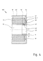
- Fig. 4 a detail of a second embodiment in section.
- Fig. 1 the filter unit 100 according to the invention is shown in a schematic sectional view.
- a filter element 10 Inside a case, which consists of a Housing pot 40 and a cover member 20 is formed, a filter element 10 is arranged.
- the filter element 10 comprises a filter bellows 11, which is formed, for example, from a pleated filter paper wound into a cylinder tube body.
- the filter bellows 11 is connected at its two ends with end plates 13, 14 and forms together with these a cylindrical, hollow body.
- the sealing of the ring-shaped end disk 14 relative to the housing pot or the housing bottom 41 is essential, since otherwise the dirt-laden medium could flow past the filter element 10 directly to the outlet opening 43.
- the end plate 14 has a shoulder 15 with a thread 16.
- the shoulder 15 is formed conically with a cone angle ⁇ of 8 ° to 12 ° with respect to the central axis.
- a shoulder 42 which is provided with a conical internal thread 46, in which the external thread 16 of the paragraph 15 can engage.
- the thread filter element 10 and housing part 40 can be firmly connected.
- a ring seal 19 seals the gap between the end plate 14 of the filter element 14 and the housing bottom 41.
- a shoulder 17 is formed, which is provided in the illustrated embodiment with a groove 18.
- an elevation 21 is formed on the end face 27, from which pins 22 extend radially inwardly, which can engage in the grooves 18, so that a bayonet connection between the cover element 20 and the filter element 10 is formed
- Fig. 1 only schematically illustrated filter unit is in Fig. 2 again shown in section through a specific embodiment.
- the filter element 10 is surrounded by an additional collar 28, so that there is an annular gap between the outside of the collar 28 and the housing wall of the housing part 20.
- a collar 48 comprises the filter element 10.
- Fig. 3a shows in detail the connection between the filter element 10 and the housing pot 40 of the filter unit 100.
- To the end plate 14 of the filter element 10 of the shoulder 15 is formed, which protrudes in the direction of the housing bottom 41 and is provided with an external thread 16.
- the shoulder 15 encloses a central flow channel 12 in the filter element 10, which opens to an outlet opening 43 in the housing bottom 41.
- On the housing bottom 41 of the shoulder 42 is formed, the conical internal thread 46 is compatible with the external thread 16 of the shoulder 15 at the end plate 14.
- each of the webs of the thread 15 are directly in front of the grooves of the thread 46 and vice versa.
- a rotation of about 1 to 1 1 ⁇ 2 revolutions is then sufficient to fully engage the threads and to screw the filter element 10 firmly into the shoulder 42 of the housing bottom 41.
- Fig. 3b represented where the threads 16, 46 are engaged with each other and the filter element 10 has been moved axially so far on the housing bottom 41, that a ring seal 19 is pressed firmly. This prevents air from the flow path located on the outer circumference of the housing element 40 to flow past the filter element 10 through the outlet opening 43.
- Fig. 4 shows a kinematically reverse Austechnologieüngsbeispiels a filter unit 100 ', in which at the housing bottom 41' a shoulder 42 'is provided with external thread and the filter element 10' is a threaded bore 16 'is provided. Also in this embodiment, the connection is made via two conical threads 16 ', 46' with a cone angle ⁇ . Again, in the installed state, a ring seal 19 'between end plate 14' and housing bottom 41 'is pressed.
Landscapes
- Chemical & Material Sciences (AREA)
- Chemical Kinetics & Catalysis (AREA)
- Physics & Mathematics (AREA)
- Geometry (AREA)
- Filtering Of Dispersed Particles In Gases (AREA)
- Infusion, Injection, And Reservoir Apparatuses (AREA)
- Electrical Discharge Machining, Electrochemical Machining, And Combined Machining (AREA)
- Filtration Of Liquid (AREA)
- Sampling And Sample Adjustment (AREA)
Description
- Die Erfindung betrifft eine Filtereinheit mit einem Gehäuse und einem darin einsetzbaren, zylindrischen Filterelement welches endseitig jeweils mit eine Endscheibe verbunden ist.
- Filtereinheiten sind bekannt, die mit ihrem Gehäuse ein im Wesentlichen zylindrisches Filterelement umfassen, das nach Abnahme eines Deckels zugänglich ist und ausgetauscht werden kann. Zur Befestigung des filterelements am Boden des Gehäuses sind Steck- und Schraubverbindungen bekannt. Steckverbindungen sind nicht immer ausreichend fest, um das Filterelement mit seinen Dichtflächen axial gegen den Gehäuseboden zu drücken, um eine gute Abdichtung zwischen Filterelement und Gehäuseboden bewirken zu können. Bei Schraubverbindungen müssen mehrere Gewindegänge vorgesehen sein, um eine ausreichend feste Verschraubung bewirken zu können, so dass das Losschrauben des Filterelements bei der Wartung entsprechend viel Zeit benötigt. Beim Aufschrauben des Deckels ist zusätlich sorgfältig darauf zu achten, dass die Gewindegänge von Deckeln und Gehäuse exakt ineinander eingeführt werden, da sonst das Filtergehäuse beschädigt werden kann.
- Weiterhin sind Bajonettverschlüsse bekannt, die jedoch den Nachteil haben, nur punktuell hohe Anpresskräfte erzielen zu können, wohingegen die zwischen den Verriegelungen liegenden Bereiche, gerade bei verformbaren Kunststoffelementen, wegfedern können. Eine ringförmige Dichtung zwischen Deckel und Gehäuse wird gerade bei großen Durchmessern der Luftfiltereinheit bei einem Bajonettverschluss möglicherweise nicht ausreichend fest angepresst. Da der Vorschub in axialer Richtung bei einer Bajonettverriegelung nicht beeinflusst werden kann, ist die nötige Vorspannung der Dichtung vom Bediener nicht einstellbar, so dass möglicherweise aufgrund von Toleranzen in der Dichtungsgeometrie zu Undichtigkeiten kommen kann.
- Aus der
WO2007/085427 A1 ist ein Filterelement bekannt, welches an einer Endscheibe ein konisch ausgebildetes Innengewinde aufweist. - Aufgabe der Erfindung ist es somit, bei einer Filtereinheit der eingangs genannten Art eine im Betrieb feste und im Wartungsfall schnell zu lösende Verbindung von Filterelement und Gehäuse zu schaffen.
- Diese Aufgabe wird durch eine Filtereinheit mit den Merkmalen des Anspruchs 1 gelöst.
- Aufgrund der Konizität von Gewindeabsatz und Gewindebohrung ist eine Selbstzentrierung gegeben, wenn das Filterelement auf das Gehäuseelement geschoben wird. Es genügt dann eine Drehung um einen relativ kleinen Winkel, um eine Vielzahl von Gewindegängen miteinander in Eingriff zu bringen und so eine entsprechend hohe Festigkeit der Gewindeverbindung gegenüber axialen Kräften zu bewirken.
- Als vorteilhaft hat sich hier ein Sägezahngewinde erwiesen, das als Bewegungsgewinde gut geeignet ist. Selbstverständlich sind auch andere Gewindeformen möglich.
- Beispielsweise ist ein konisches Sägezahngewinde geeignet, das bei einem Durchmesser von ca. 100 mm 4 bis 5 Gewindegänge aufweist, die in einem Kegelwinkel von 6° bis 12° angeordnet sind.
- Weitere vorteilhafte Ausgestaltungen der Erfindung sind den weiteren Unteransprüchen zu entnehmen und werden nachfolgend mit Bezug auf die Ausführungsbeispiele beschrieben.
- Die Erfindung wird nachfolgend mit Bezug auf die Zeichnung näher erläutert. Die Figuren zeigen im Einzelnen:
-
Fig. 1 einen schematischen Schnitt durch eine erste Ausführungsform einer Filtereinheit, -
Fig. 2 einen Schnitt durch eine Filtereinheit in perspektivischer Ansicht, -
Fig. 3a ,3b ein Detail der ersten Ausführungsform in verschiedenen Montagestadien, jeweils im Schnitt und -
Fig. 4 ein Detail einer zweiten Ausführungsform im Schnitt. - In
Fig. 1 ist die erfindungsgemäße Filtereinheit 100 in einer schematischen Schnittdarstellung gezeigt. Im Inneren eines Gehäuses, welches aus einem Gehäusetopf 40 und einem Deckelelement 20 gebildet ist, ist ein Filterelement 10 angeordnet. Das Filterelement 10 umfasst einen Filterbalg 11, der beispielsweise aus einem zu einem Zylinderrohrkörper gewickelten, plissierten Filterpapier gebildet ist. Der Filterbalg 11 ist an seinen beiden Enden mit Endscheiben 13, 14 verbunden und bildet mit diesen zusammen einen zylindrischen, hohlen Körper. Luft gelangt an einem nicht dargestellten Einlaufstutzen des Gehäuses vom Außenumfang her ins Gehäuse, strömt durch den Filterbalg 11 des Filterelements 10 und dessen zentralen Strömungskanal 12 und strömt an einer zentral an einem Gehäuseboden 41 angeordneten Auslassöffnung 43 wieder heraus. - Dabei ist insbesondere die Abdichtung der ringförmig ausgebildeten Endscheibe 14 gegenüber dem Gehäusetopf bzw. dem Gehäuseboden 41 wesentlich, da ansonsten das Schmutz befrachtete Medium am Filterelement 10 vorbei direkt zum Auslassöffnung 43 strömen könnte. Hierzu besitzt die Endscheibe 14 einen Absatz 15 mit einem Gewinde 16. Der Absatz 15 ist konisch mit einem Kegelwinkel α von 8° bis 12° in Bezug auf die Mittelachse ausgebildet.
- Gegenüberliegend befindet sich an dem Gehäuseboden 41 ein Absatz 42, der mit einem konischen Innengewinde 46 versehen ist, in welches das Außengewinde 16 des Absatzes 15 eingreifen kann. Über die Gewinde können Filterelement 10 und Gehäuseteil 40 fest miteinander verbunden werden.
- Eine Ringdichtung 19 dichtet den Spalt zwischen der Endscheibe 14 des Filterelements 14 und dem Gehäuseboden 41 ab.
- An der anderen Endscheibe 13 des Filterelements 10 ist ein Absatz 17 angeformt, der im dargestellten Ausführungsbeispiel mit einer Rille 18 versehen ist. Am Deckelelement 20 des Gehäuses ist an die Stirnseite 27 eine Überhöhung 21 angeformt, von der aus sich Zapfen 22 radial nach innen erstrecken, welche in die Rillen 18 eingreifen können, so dass eine Bajonettverbindung zwischen Deckelelement 20 und Filterelement 10 ausgebildet ist
- Die in
Fig. 1 nur schematisch dargestellte Filtereinheit ist inFig. 2 nochmals im Schnitt durch ein konkretes Ausführungsbeispiel gezeigt. Deutlich erkennbar ist an dem innen liegenden, ebenfalls geschnittenen Filterelement 10 ein Innenrohr, welches keine geschlossene Außenwandung aufweist, sondern eine Gitterstruktur hat, um eine radiale Luftströmung durch den Filterbalg 11 in den zentralen Strömungskanal 12 so wenig wie möglich zu behindern. - Im Bereich des Deckels 20 ist das filterelement 10 von einem zusätzlichen Kragen 28 umfasst, so dass sich zwischen der Außenseite des Kragens 28 und der Gehäusewandung des Gehäuseteils 20 ein Ringspalt ergibt. Gleiches gilt für die gegenüberliegende Seite, wo ein Kragen 48 das Filterelement 10 umfasst. Bei tangentialer Einströmung der Rohluft am Einlaufstutzen läuft die in das Gehäuse eingeleitete Luftmasse am Innenumfang der Gehäusewandung um, wodurch schwere Staubpartikel abgeschieden werden und an dem Abscheiderstutzen 29 abfließen können, und strömt dann radial von außen nach innen durch den Filterbalg 11.
-
Fig. 3a zeigt im Detail die Verbindung zwischen dem Filterelement 10 und dem Gehäusetopf 40 der Filtereinheit 100. An die Endscheibe 14 des Filterelements 10 ist der Absatz 15 angeformt, der in Richtung des Gehäusebodens 41 hervorspringt und mit einem Außengewinde 16 versehen ist. Wie durch die gestrichelten Linien angedeutet, umschließt der Absatz 15 einen zentralen Strömungskanal 12 im Filterelement 10, der sich zu einer Auslassöffnung 43 im Gehäuseboden 41 hin öffnet. Am Gehäuseboden 41 ist der Absatz 42 angeformt, dessen konisches Innengewinde 46 kompatibel zum Außengewinde 16 des Absatzes 15 an der Endscheibe 14 ist. - In der in
Fig. 3a eingestellten Situation befindet sich das Filterelement 10 mit seinem Absatz 15 bereits innerhalb der Gewindebohrung des Ansatzes 42, jedoch stehen aufgrund der Konizität die Gewindegänge bei dieser axialen Lage des Filterelements 10 gegenüber dem Gehäuseboden 41 noch nicht miteinander im Eingriff. Zur Verdeutlichung ist inFig. 3a die Spaltweite zwischen Außengewinde 16 und Innengewinde 46 etwas überzeichnet. - Wird das Filterelement 10 noch weiter vorgeschoben, dann liegen jeweils die Stege des Gewindes 15 direkt vor den Rillen des Gewindes 46 und umgekehrt. Es genügt dann eine Drehung von etwa 1 bis 1 ½ Umdrehungen, um die Gewindegänge vollends in Eingriff zu bringen und das Filterelement 10 fest in den Absatz 42 des Gehäuseboden 41 einzuschrauben.
- Die Endsituation ist in
Fig. 3b dargestellt, wo die Gewinde 16, 46 miteinander im Eingriff sind und das Filterelement 10 soweit axial auf den Gehäuseboden 41 zu bewegt worden ist, dass eine Ringdichtung 19 fest angepresst wird. Diese verhindert, dass Luft von dem am Außenumfang des Gehäuseelements 40 befindlichen Strömungsweg am Fitterelement 10 vorbei durch die Auslassöffnung 43 strömen kann. -
Fig. 4 zeigt ein kinematisch umgekehrtes Ausführüngsbeispiel einer Filtereinheit 100' , bei der am Gehäuseboden 41' ein Absatz 42' mit Außengewinde vorgesehen ist und am Filterelement 10' eine Gewindebohrung 16' vorgesehen ist. Auch bei diesem Ausführungsbeispiel wird die Verbindung über zwei konische Gewinde 16', 46' mit einem Kegelwinkel α hergestellt. Wiederum ist im Einbauzustand eine Ringdichtung 19' zwischen Endscheibe 14' und Gehäuseboden 41' verpresst. - Bei dem Ausführungsbeispiel nach
Fig. 4 ist darüber hinaus vorgesehen, dass ein Rastzapfen 14.1' von der Endscheibe 14' hervorsteht. Wird das Filterelement 10' über die Gewinde 16', 46' verschraubt, so rastet der Rastvorsprung 14.1' in der vorgesehenen Endlage in einer entsprechenden Ausnehmung 44' am Gehäuseboden ein, wodurch eine Verdrehsicherung gegeben ist. Durch mehrere Ausnehmungen können verschiedene Rastpositionen vorgegeben werden.
Claims (7)
- Filtereinheit (100) mit wenigstens einem Gehäuseelement (40) und einem darin einsetzbaren, zylindrischen Filterelement (10) welches endseitig jeweils mit einer Endscheibe (13, 14) verbunden ist, dadurch gekennzeichnet, dass ein Gehäuseboden (41) ein Gewinde (46) aufweist und das Filterelement (10) an wenigstens einer Endscheibe (13) einen Absatz (15) mit einem Gegengewinde (16) aufweist, wobei das Gewinde und das Gegengewinde jeweils konisch ausgebildet und miteinander in Eingriff zu bringen sind, wobei das Gewinde (46) ein Innengewinde und das Gegengewinde (16) ein Außengewinde ist.
- Filtereinheit (100; 100') nach Anspruch 1, dadurch gekennzeichnet, dass die Gewinde (16, 46; 16' , 46') einen Teil eines sich entlang der Mittelachse des Filterelements (10; 10') und des Gehäuses (40; 40') erstreckenden Strömungskanal (12; 12') und/oder eine Gehäuseöffnung (43, 43') umschließen.
- Filtereinheit (100; 100' nach Anspruch 1 oder 2, dadurch gekennzeichnet, dass das konische Gewinde (16, 46; 16' , 46') ein Sägezahngewinde ist.
- Filtereinheit (100) nach wenigstens einem der Ansprüche 1 bis 3, dadurch gekennzeichnet, dass die Gewinde (16, 46; 16' , 46') einen Kegelwinkel α von 6° bis 12° aufweisen.
- Filtereinheit (100, 100') nach wenigstens einem der Ansprüche 1 bis 4, dadurch gekennzeichnet, dass bei einem am Gehäuseboden (41, 41) angeschraubten Filterelement (10; 10') 4 bis 5 Gewindegänge beider Gewinde (16, 46; 16' , 46') miteinander in Eingriff sind.
- Filtereinheit (100') nach wenigstens einem der Ansprüche 1 bis 5, dadurch gekennzeichnet, dass im Einbauzustand des Filterelements zwischen der Endscheibe (14') des Filterelements (10') und dem Gehäuseboden (41') in wenigstens einer Winkellage eine Rastverbindung ausgebildet ist.
- Filtereinheit (100') nach Anspruch 6, dadurch gekennzeichnet, dass die Rastverbindung durch einen halbkugelförmigen Rastvorsprung (14.1') an der Endscheibe (14') und eine Ausnehmung (44') im Gehäuseboden (41') auszubilden ist.
Priority Applications (2)
| Application Number | Priority Date | Filing Date | Title |
|---|---|---|---|
| EP10172513A EP2241365B1 (de) | 2006-08-03 | 2007-07-12 | Filtereinheit mit einem konischen Gewinde |
| PL10172513T PL2241365T3 (pl) | 2006-08-03 | 2007-07-12 | Jednostka filtracyjna z gwintem stożkowym |
Applications Claiming Priority (2)
| Application Number | Priority Date | Filing Date | Title |
|---|---|---|---|
| DE202006011990U DE202006011990U1 (de) | 2006-08-03 | 2006-08-03 | Filtereinheit mit einem radial geteilten Gehäuse |
| PCT/EP2007/057170 WO2008015088A1 (de) | 2006-08-03 | 2007-07-12 | Filtereinheit mit einem konischen gewinde |
Related Child Applications (1)
| Application Number | Title | Priority Date | Filing Date |
|---|---|---|---|
| EP10172513.3 Division-Into | 2010-08-11 |
Publications (2)
| Publication Number | Publication Date |
|---|---|
| EP2046478A1 EP2046478A1 (de) | 2009-04-15 |
| EP2046478B1 true EP2046478B1 (de) | 2011-01-05 |
Family
ID=38521745
Family Applications (2)
| Application Number | Title | Priority Date | Filing Date |
|---|---|---|---|
| EP07787441A Active EP2046478B1 (de) | 2006-08-03 | 2007-07-12 | Filtereinheit mit einem konischen gewinde |
| EP10172513A Active EP2241365B1 (de) | 2006-08-03 | 2007-07-12 | Filtereinheit mit einem konischen Gewinde |
Family Applications After (1)
| Application Number | Title | Priority Date | Filing Date |
|---|---|---|---|
| EP10172513A Active EP2241365B1 (de) | 2006-08-03 | 2007-07-12 | Filtereinheit mit einem konischen Gewinde |
Country Status (9)
| Country | Link |
|---|---|
| US (1) | US8097154B2 (de) |
| EP (2) | EP2046478B1 (de) |
| KR (1) | KR101500763B1 (de) |
| CN (1) | CN101500684B (de) |
| AT (2) | ATE494054T1 (de) |
| DE (2) | DE202006011990U1 (de) |
| ES (1) | ES2380457T3 (de) |
| PL (1) | PL2241365T3 (de) |
| WO (1) | WO2008015088A1 (de) |
Families Citing this family (21)
| Publication number | Priority date | Publication date | Assignee | Title |
|---|---|---|---|---|
| WO2007056589A2 (en) | 2005-11-09 | 2007-05-18 | Donaldson Company, Inc. | Seal arrangement for filter element; filter element assembly: and, methods |
| DE102004029225A1 (de) | 2004-06-17 | 2006-01-12 | Hydac Filtertechnik Gmbh | Filtervorrichtung und Filterelement |
| DE102007017091A1 (de) * | 2007-04-10 | 2008-10-16 | Mahle International Gmbh | Ringfilterelement |
| DE202008010504U1 (de) * | 2008-08-07 | 2009-12-17 | Mann+Hummel Gmbh | Filtersystem zur Filtrierung von Fluiden |
| DE102008048155A1 (de) | 2008-09-19 | 2010-03-25 | Hydac Filtertechnik Gmbh | Filtervorrichtung und Filterelement |
| DE102010010964B4 (de) * | 2010-03-10 | 2022-12-22 | Mann+Hummel Gmbh | Filterelement zur Fluidfiltration und Luftfiltereinheit, insbesondere für Ansaugluft von Brennkraftmaschinen. |
| DE102012020574A1 (de) * | 2012-10-22 | 2014-04-24 | Mann + Hummel Gmbh | Filter |
| DE102013008986B4 (de) * | 2013-05-28 | 2020-04-23 | Mann+Hummel Gmbh | Filtereinrichtung, insbesondere Flüssigkeitsfilter |
| US9598919B1 (en) | 2015-09-30 | 2017-03-21 | Reme, L.L.C. | Modified filter screen |
| WO2017058220A1 (en) * | 2015-09-30 | 2017-04-06 | Reme, L.L.C. | Modified filter screen |
| US10413855B2 (en) | 2016-02-12 | 2019-09-17 | Donalson Company, Inc. | Filter elements, air cleaner assemblies, and methods of use and assembly |
| US11331606B2 (en) | 2016-03-01 | 2022-05-17 | Cummins Filtration Ip, Inc. | Torsional no filter no run system and method |
| DE202016102187U1 (de) * | 2016-04-25 | 2017-07-26 | Rath Gmbh - Zweigniederlassung Mönchengladbach | Filterelement zur Filtration von Abgasen oder Prozessgasen |
| US11554338B2 (en) | 2016-12-01 | 2023-01-17 | Donaldson Company, Inc. | Filter elements, air cleaner assemblies, and methods of use and assembly |
| CN106642432B (zh) * | 2016-12-30 | 2019-05-03 | 深圳市汇健医疗工程有限公司 | 一种高效过滤器密封装置 |
| RU2767116C2 (ru) | 2017-03-20 | 2022-03-16 | Дональдсон Компани, Инк. | Система, содержащая соединитель для соединения с элементом фильтрации текучей среды, элемент фильтрации текучей среды и способ их изготовления |
| WO2018197614A1 (en) * | 2017-04-28 | 2018-11-01 | Leybold Gmbh | Filter system |
| US20200114288A1 (en) * | 2018-10-10 | 2020-04-16 | Schroeder Industries, Llc | Filter assembly with authenticating filter element coupling and replaceable drop-in twist locking filter element therefor |
| CN112169396B (zh) * | 2020-10-27 | 2025-08-08 | 武汉易知鸟科技有限公司 | 一种盐电解质溶液多级过滤装置 |
| TWI761127B (zh) * | 2020-11-30 | 2022-04-11 | 謝典澤 | 隨身式空氣清淨裝置 |
| DE102024107682A1 (de) * | 2024-03-18 | 2025-09-18 | Mann+Hummel Gmbh | Filterelement, Ionentauscher-Filterelement und Filtersystem |
Family Cites Families (25)
| Publication number | Priority date | Publication date | Assignee | Title |
|---|---|---|---|---|
| US654592A (en) * | 1900-01-23 | 1900-07-31 | William Henry Barr | Filtering apparatus. |
| US1000000A (en) * | 1910-04-25 | 1911-08-08 | Francis H Holton | Vehicle-tire. |
| US3237771A (en) * | 1963-09-06 | 1966-03-01 | Fram Corp | Water-sensitive filter and flow monitor |
| FR1489013A (fr) * | 1965-11-05 | 1967-07-21 | Vallourec | Joint d'assemblage pour tubes métalliques |
| US3415382A (en) * | 1966-07-18 | 1968-12-10 | John E. Martin | Filter utilizing glass balls for filtering fluids |
| CA962605A (en) * | 1968-11-26 | 1975-02-11 | David Rosenberg | Disposable filter assembly |
| DE2706017A1 (de) * | 1977-02-12 | 1978-08-17 | Ultrafilter Gmbh | Filterelement |
| DE2915730C2 (de) * | 1979-04-19 | 1987-04-23 | Kronsbein, Dirk-Gustav, 4000 Düsseldorf | Patronenfilter |
| US4610467A (en) * | 1981-07-06 | 1986-09-09 | Dril-Quip, Inc. | Connector |
| US4537429A (en) * | 1983-04-26 | 1985-08-27 | Hydril Company | Tubular connection with cylindrical and tapered stepped threads |
| DE8714819U1 (de) * | 1987-11-06 | 1988-01-07 | Pall Deutschland GmbH, 6072 Dreieich | Kunststoffgehäuse |
| DE3805138A1 (de) * | 1988-02-19 | 1989-08-31 | Reinhold Fries | Filter |
| DE8804930U1 (de) * | 1988-04-14 | 1988-07-07 | Brahm, Wilhelm, 7247 Sulz | Filtervorrichtung zum Filtern von gasförmigen Medien |
| US5164082A (en) * | 1991-12-17 | 1992-11-17 | Lin Tzu Fu | Water filter having lever controlled plunger |
| US5667678A (en) * | 1995-04-13 | 1997-09-16 | Advanced Performance Technology, Inc. | Plastic fluid filter and method for assembling same |
| US5961678A (en) | 1995-07-07 | 1999-10-05 | Flair Corporation | Filter drainage layer attachment |
| US5985143A (en) * | 1998-09-08 | 1999-11-16 | Lin; Maw-Chang | Structure water filter outer shell |
| US6235194B1 (en) * | 2000-03-08 | 2001-05-22 | Parker-Hannifin Corporation | Recharge and filter assembly with replaceable cartridge |
| DE10261314A1 (de) * | 2002-12-27 | 2004-07-08 | Mann + Hummel Gmbh | Kraftstoffilter |
| US7434697B2 (en) * | 2004-02-16 | 2008-10-14 | Fleetguard Inc. | Disposable, spin-on filter |
| DE102004029225A1 (de) | 2004-06-17 | 2006-01-12 | Hydac Filtertechnik Gmbh | Filtervorrichtung und Filterelement |
| US7077955B1 (en) * | 2005-05-10 | 2006-07-18 | Mao-Chang Lin | Joint used in one of a water inlet or water outlet of a filter cylinder or a filter casing |
| DE102005026292A1 (de) * | 2005-06-08 | 2006-12-14 | Robert Bosch Gmbh | Filtereinrichtung mit einem Filterelement |
| DE102006003949B4 (de) | 2006-01-26 | 2008-04-30 | Carl Freudenberg Kg | Filterelement mit Anschlusselement |
| EP1984672A2 (de) | 2006-01-30 | 2008-10-29 | Rational AG | Verfahren zum führen von reinigungsvorgängen in einer fluidaufnahmevorrichtung eines nahrungsmittelbehandlungsgeräts sowie fluidaufnahmevorrichtung und nahrungsmittelbehandlungsgerät hierfür |
-
2006
- 2006-08-03 DE DE202006011990U patent/DE202006011990U1/de not_active Expired - Lifetime
-
2007
- 2007-07-12 DE DE502007006203T patent/DE502007006203D1/de active Active
- 2007-07-12 ES ES10172513T patent/ES2380457T3/es active Active
- 2007-07-12 KR KR1020097002109A patent/KR101500763B1/ko not_active Expired - Fee Related
- 2007-07-12 US US12/376,012 patent/US8097154B2/en active Active
- 2007-07-12 CN CN2007800288271A patent/CN101500684B/zh active Active
- 2007-07-12 AT AT07787441T patent/ATE494054T1/de active
- 2007-07-12 EP EP07787441A patent/EP2046478B1/de active Active
- 2007-07-12 AT AT10172513T patent/ATE542589T1/de active
- 2007-07-12 WO PCT/EP2007/057170 patent/WO2008015088A1/de not_active Ceased
- 2007-07-12 PL PL10172513T patent/PL2241365T3/pl unknown
- 2007-07-12 EP EP10172513A patent/EP2241365B1/de active Active
Also Published As
| Publication number | Publication date |
|---|---|
| DE502007006203D1 (de) | 2011-02-17 |
| KR20090034945A (ko) | 2009-04-08 |
| EP2241365A1 (de) | 2010-10-20 |
| EP2046478A1 (de) | 2009-04-15 |
| ATE542589T1 (de) | 2012-02-15 |
| ATE494054T1 (de) | 2011-01-15 |
| US20100181243A1 (en) | 2010-07-22 |
| ES2380457T3 (es) | 2012-05-11 |
| PL2241365T3 (pl) | 2012-07-31 |
| WO2008015088A1 (de) | 2008-02-07 |
| CN101500684A (zh) | 2009-08-05 |
| KR101500763B1 (ko) | 2015-03-09 |
| DE202006011990U1 (de) | 2007-12-20 |
| US8097154B2 (en) | 2012-01-17 |
| CN101500684B (zh) | 2012-04-11 |
| EP2241365B1 (de) | 2012-01-25 |
Similar Documents
| Publication | Publication Date | Title |
|---|---|---|
| EP2046478B1 (de) | Filtereinheit mit einem konischen gewinde | |
| EP2046479B2 (de) | Luftfiltereinheit mit einem radial geteilten gehäuse | |
| EP2373398B1 (de) | Filterelement und druckluftfilter zum abscheiden von fremdstoffen aus einem druckluftstrom | |
| EP1967247B1 (de) | Druckluft-Filter und zugehöriger Adapter | |
| EP2862613B1 (de) | Filtersystem mit Dichtung | |
| EP4161677B1 (de) | Filtervorrichtung | |
| EP2704813B1 (de) | Endscheibe für ein filterelement, entsprechendes filterelement und entsprechender filter | |
| EP3352876A1 (de) | Filtervorrichtung mit kupplungselement | |
| DE102013020499A1 (de) | Filtergehäuse, Fluidfilter sowie Verfahren zur Montage des Deckels des Filtergehäuses auf einem Nippel des Fluidfilters | |
| EP1834686A1 (de) | Filtervorrichtung | |
| EP4357000B1 (de) | Filtervorrichtung | |
| EP4312681B1 (de) | Filter mit zentrierung | |
| DE602004012297T2 (de) | Rückspülbarer filter mit schleuderabreinigung | |
| EP4171781B1 (de) | Filtereinrichtung mit einem filterelement | |
| WO2022218701A1 (de) | Filtervorrichtung | |
| DE102011003537A1 (de) | Ventilgehäusekörper | |
| DE102004029641B4 (de) | Vorrichtung zum Filtern von Fluiden | |
| DE102015007182B4 (de) | Filterelement und Filtersystem | |
| EP3544714B1 (de) | Filterelement und fluidfilter mit drehbarem bajonettring | |
| EP3328701A1 (de) | Kupplungssystem, insbesondere kupplungssystem zur pneumatischen verbindung einer pneumatischen bremsanlage eines zugfahrzeuges und eines anhängers | |
| EP4061505A1 (de) | Luftfilter mit einem primärluftauslass und einem sekundärluftauslass | |
| EP4098344B1 (de) | Filtereinrichtung mit filterelement | |
| EP2006592B1 (de) | Kupplung | |
| DE102023003101A1 (de) | Filtervorrichtung und Filterelement | |
| DE102018206022B4 (de) | Wartungsgerät |
Legal Events
| Date | Code | Title | Description |
|---|---|---|---|
| PUAI | Public reference made under article 153(3) epc to a published international application that has entered the european phase |
Free format text: ORIGINAL CODE: 0009012 |
|
| 17P | Request for examination filed |
Effective date: 20090202 |
|
| AK | Designated contracting states |
Kind code of ref document: A1 Designated state(s): AT BE BG CH CY CZ DE DK EE ES FI FR GB GR HU IE IS IT LI LT LU LV MC MT NL PL PT RO SE SI SK TR |
|
| AX | Request for extension of the european patent |
Extension state: AL BA HR MK RS |
|
| RIN1 | Information on inventor provided before grant (corrected) |
Inventor name: BAUDER, RALF Inventor name: DWORATZEK, KLEMENS Inventor name: ACKERMANN, STEFFEN |
|
| 17Q | First examination report despatched |
Effective date: 20090526 |
|
| GRAP | Despatch of communication of intention to grant a patent |
Free format text: ORIGINAL CODE: EPIDOSNIGR1 |
|
| GRAS | Grant fee paid |
Free format text: ORIGINAL CODE: EPIDOSNIGR3 |
|
| GRAA | (expected) grant |
Free format text: ORIGINAL CODE: 0009210 |
|
| AK | Designated contracting states |
Kind code of ref document: B1 Designated state(s): AT BE BG CH CY CZ DE DK EE ES FI FR GB GR HU IE IS IT LI LT LU LV MC MT NL PL PT RO SE SI SK TR |
|
| REG | Reference to a national code |
Ref country code: GB Ref legal event code: FG4D Free format text: NOT ENGLISH |
|
| REG | Reference to a national code |
Ref country code: CH Ref legal event code: EP |
|
| REG | Reference to a national code |
Ref country code: IE Ref legal event code: FG4D Free format text: LANGUAGE OF EP DOCUMENT: GERMAN |
|
| REF | Corresponds to: |
Ref document number: 502007006203 Country of ref document: DE Date of ref document: 20110217 Kind code of ref document: P |
|
| REG | Reference to a national code |
Ref country code: DE Ref legal event code: R096 Ref document number: 502007006203 Country of ref document: DE Effective date: 20110217 |
|
| REG | Reference to a national code |
Ref country code: NL Ref legal event code: VDEP Effective date: 20110105 |
|
| PG25 | Lapsed in a contracting state [announced via postgrant information from national office to epo] |
Ref country code: SI Free format text: LAPSE BECAUSE OF FAILURE TO SUBMIT A TRANSLATION OF THE DESCRIPTION OR TO PAY THE FEE WITHIN THE PRESCRIBED TIME-LIMIT Effective date: 20110105 |
|
| LTIE | Lt: invalidation of european patent or patent extension |
Effective date: 20110105 |
|
| PG25 | Lapsed in a contracting state [announced via postgrant information from national office to epo] |
Ref country code: SE Free format text: LAPSE BECAUSE OF FAILURE TO SUBMIT A TRANSLATION OF THE DESCRIPTION OR TO PAY THE FEE WITHIN THE PRESCRIBED TIME-LIMIT Effective date: 20110105 Ref country code: LV Free format text: LAPSE BECAUSE OF FAILURE TO SUBMIT A TRANSLATION OF THE DESCRIPTION OR TO PAY THE FEE WITHIN THE PRESCRIBED TIME-LIMIT Effective date: 20110105 Ref country code: GR Free format text: LAPSE BECAUSE OF FAILURE TO SUBMIT A TRANSLATION OF THE DESCRIPTION OR TO PAY THE FEE WITHIN THE PRESCRIBED TIME-LIMIT Effective date: 20110406 Ref country code: LT Free format text: LAPSE BECAUSE OF FAILURE TO SUBMIT A TRANSLATION OF THE DESCRIPTION OR TO PAY THE FEE WITHIN THE PRESCRIBED TIME-LIMIT Effective date: 20110105 Ref country code: PT Free format text: LAPSE BECAUSE OF FAILURE TO SUBMIT A TRANSLATION OF THE DESCRIPTION OR TO PAY THE FEE WITHIN THE PRESCRIBED TIME-LIMIT Effective date: 20110505 Ref country code: ES Free format text: LAPSE BECAUSE OF FAILURE TO SUBMIT A TRANSLATION OF THE DESCRIPTION OR TO PAY THE FEE WITHIN THE PRESCRIBED TIME-LIMIT Effective date: 20110416 Ref country code: IS Free format text: LAPSE BECAUSE OF FAILURE TO SUBMIT A TRANSLATION OF THE DESCRIPTION OR TO PAY THE FEE WITHIN THE PRESCRIBED TIME-LIMIT Effective date: 20110505 |
|
| REG | Reference to a national code |
Ref country code: IE Ref legal event code: FD4D |
|
| PG25 | Lapsed in a contracting state [announced via postgrant information from national office to epo] |
Ref country code: FI Free format text: LAPSE BECAUSE OF FAILURE TO SUBMIT A TRANSLATION OF THE DESCRIPTION OR TO PAY THE FEE WITHIN THE PRESCRIBED TIME-LIMIT Effective date: 20110105 Ref country code: PL Free format text: LAPSE BECAUSE OF FAILURE TO SUBMIT A TRANSLATION OF THE DESCRIPTION OR TO PAY THE FEE WITHIN THE PRESCRIBED TIME-LIMIT Effective date: 20110105 Ref country code: CY Free format text: LAPSE BECAUSE OF FAILURE TO SUBMIT A TRANSLATION OF THE DESCRIPTION OR TO PAY THE FEE WITHIN THE PRESCRIBED TIME-LIMIT Effective date: 20110105 Ref country code: BG Free format text: LAPSE BECAUSE OF FAILURE TO SUBMIT A TRANSLATION OF THE DESCRIPTION OR TO PAY THE FEE WITHIN THE PRESCRIBED TIME-LIMIT Effective date: 20110405 Ref country code: NL Free format text: LAPSE BECAUSE OF FAILURE TO SUBMIT A TRANSLATION OF THE DESCRIPTION OR TO PAY THE FEE WITHIN THE PRESCRIBED TIME-LIMIT Effective date: 20110105 |
|
| PG25 | Lapsed in a contracting state [announced via postgrant information from national office to epo] |
Ref country code: DK Free format text: LAPSE BECAUSE OF FAILURE TO SUBMIT A TRANSLATION OF THE DESCRIPTION OR TO PAY THE FEE WITHIN THE PRESCRIBED TIME-LIMIT Effective date: 20110105 Ref country code: IE Free format text: LAPSE BECAUSE OF FAILURE TO SUBMIT A TRANSLATION OF THE DESCRIPTION OR TO PAY THE FEE WITHIN THE PRESCRIBED TIME-LIMIT Effective date: 20110105 Ref country code: EE Free format text: LAPSE BECAUSE OF FAILURE TO SUBMIT A TRANSLATION OF THE DESCRIPTION OR TO PAY THE FEE WITHIN THE PRESCRIBED TIME-LIMIT Effective date: 20110105 |
|
| PLBE | No opposition filed within time limit |
Free format text: ORIGINAL CODE: 0009261 |
|
| STAA | Information on the status of an ep patent application or granted ep patent |
Free format text: STATUS: NO OPPOSITION FILED WITHIN TIME LIMIT |
|
| PG25 | Lapsed in a contracting state [announced via postgrant information from national office to epo] |
Ref country code: SK Free format text: LAPSE BECAUSE OF FAILURE TO SUBMIT A TRANSLATION OF THE DESCRIPTION OR TO PAY THE FEE WITHIN THE PRESCRIBED TIME-LIMIT Effective date: 20110105 Ref country code: CZ Free format text: LAPSE BECAUSE OF FAILURE TO SUBMIT A TRANSLATION OF THE DESCRIPTION OR TO PAY THE FEE WITHIN THE PRESCRIBED TIME-LIMIT Effective date: 20110105 Ref country code: RO Free format text: LAPSE BECAUSE OF FAILURE TO SUBMIT A TRANSLATION OF THE DESCRIPTION OR TO PAY THE FEE WITHIN THE PRESCRIBED TIME-LIMIT Effective date: 20110105 |
|
| 26N | No opposition filed |
Effective date: 20111006 |
|
| PG25 | Lapsed in a contracting state [announced via postgrant information from national office to epo] |
Ref country code: MT Free format text: LAPSE BECAUSE OF FAILURE TO SUBMIT A TRANSLATION OF THE DESCRIPTION OR TO PAY THE FEE WITHIN THE PRESCRIBED TIME-LIMIT Effective date: 20110105 Ref country code: IT Free format text: LAPSE BECAUSE OF FAILURE TO SUBMIT A TRANSLATION OF THE DESCRIPTION OR TO PAY THE FEE WITHIN THE PRESCRIBED TIME-LIMIT Effective date: 20110105 |
|
| BERE | Be: lapsed |
Owner name: MANN+HUMMEL G.M.B.H. Effective date: 20110731 |
|
| REG | Reference to a national code |
Ref country code: DE Ref legal event code: R097 Ref document number: 502007006203 Country of ref document: DE Effective date: 20111006 |
|
| PG25 | Lapsed in a contracting state [announced via postgrant information from national office to epo] |
Ref country code: MC Free format text: LAPSE BECAUSE OF NON-PAYMENT OF DUE FEES Effective date: 20110731 |
|
| REG | Reference to a national code |
Ref country code: CH Ref legal event code: PL |
|
| GBPC | Gb: european patent ceased through non-payment of renewal fee |
Effective date: 20110712 |
|
| REG | Reference to a national code |
Ref country code: FR Ref legal event code: ST Effective date: 20120330 |
|
| PG25 | Lapsed in a contracting state [announced via postgrant information from national office to epo] |
Ref country code: FR Free format text: LAPSE BECAUSE OF NON-PAYMENT OF DUE FEES Effective date: 20110801 Ref country code: LI Free format text: LAPSE BECAUSE OF NON-PAYMENT OF DUE FEES Effective date: 20110731 Ref country code: BE Free format text: LAPSE BECAUSE OF NON-PAYMENT OF DUE FEES Effective date: 20110731 Ref country code: CH Free format text: LAPSE BECAUSE OF NON-PAYMENT OF DUE FEES Effective date: 20110731 |
|
| PG25 | Lapsed in a contracting state [announced via postgrant information from national office to epo] |
Ref country code: GB Free format text: LAPSE BECAUSE OF NON-PAYMENT OF DUE FEES Effective date: 20110712 |
|
| PG25 | Lapsed in a contracting state [announced via postgrant information from national office to epo] |
Ref country code: LU Free format text: LAPSE BECAUSE OF NON-PAYMENT OF DUE FEES Effective date: 20110712 |
|
| REG | Reference to a national code |
Ref country code: AT Ref legal event code: MM01 Ref document number: 494054 Country of ref document: AT Kind code of ref document: T Effective date: 20120731 |
|
| PG25 | Lapsed in a contracting state [announced via postgrant information from national office to epo] |
Ref country code: TR Free format text: LAPSE BECAUSE OF FAILURE TO SUBMIT A TRANSLATION OF THE DESCRIPTION OR TO PAY THE FEE WITHIN THE PRESCRIBED TIME-LIMIT Effective date: 20110105 |
|
| PG25 | Lapsed in a contracting state [announced via postgrant information from national office to epo] |
Ref country code: HU Free format text: LAPSE BECAUSE OF FAILURE TO SUBMIT A TRANSLATION OF THE DESCRIPTION OR TO PAY THE FEE WITHIN THE PRESCRIBED TIME-LIMIT Effective date: 20110105 Ref country code: AT Free format text: LAPSE BECAUSE OF NON-PAYMENT OF DUE FEES Effective date: 20120731 |
|
| REG | Reference to a national code |
Ref country code: DE Ref legal event code: R081 Ref document number: 502007006203 Country of ref document: DE Owner name: MANN+HUMMEL GMBH, DE Free format text: FORMER OWNER: MANN+HUMMEL GMBH, 71638 LUDWIGSBURG, DE |
|
| P01 | Opt-out of the competence of the unified patent court (upc) registered |
Effective date: 20230530 |
|
| PGFP | Annual fee paid to national office [announced via postgrant information from national office to epo] |
Ref country code: DE Payment date: 20250722 Year of fee payment: 19 |