EP2046185B1 - Mop assembly with fastener channels for cleaning substrate fastening strips - Google Patents
Mop assembly with fastener channels for cleaning substrate fastening strips Download PDFInfo
- Publication number
- EP2046185B1 EP2046185B1 EP07805084.6A EP07805084A EP2046185B1 EP 2046185 B1 EP2046185 B1 EP 2046185B1 EP 07805084 A EP07805084 A EP 07805084A EP 2046185 B1 EP2046185 B1 EP 2046185B1
- Authority
- EP
- European Patent Office
- Prior art keywords
- fastener
- mop head
- assembly
- support surface
- mop
- Prior art date
- Legal status (The legal status is an assumption and is not a legal conclusion. Google has not performed a legal analysis and makes no representation as to the accuracy of the status listed.)
- Ceased
Links
Images



Classifications
-
- A—HUMAN NECESSITIES
- A47—FURNITURE; DOMESTIC ARTICLES OR APPLIANCES; COFFEE MILLS; SPICE MILLS; SUCTION CLEANERS IN GENERAL
- A47L—DOMESTIC WASHING OR CLEANING; SUCTION CLEANERS IN GENERAL
- A47L13/00—Implements for cleaning floors, carpets, furniture, walls, or wall coverings
- A47L13/10—Scrubbing; Scouring; Cleaning; Polishing
- A47L13/20—Mops
- A47L13/24—Frames for mops; Mop heads
- A47L13/254—Plate frames
- A47L13/256—Plate frames for mops made of cloth
-
- A—HUMAN NECESSITIES
- A47—FURNITURE; DOMESTIC ARTICLES OR APPLIANCES; COFFEE MILLS; SPICE MILLS; SUCTION CLEANERS IN GENERAL
- A47L—DOMESTIC WASHING OR CLEANING; SUCTION CLEANERS IN GENERAL
- A47L13/00—Implements for cleaning floors, carpets, furniture, walls, or wall coverings
- A47L13/10—Scrubbing; Scouring; Cleaning; Polishing
- A47L13/20—Mops
- A47L13/24—Frames for mops; Mop heads
- A47L13/254—Plate frames
-
- A—HUMAN NECESSITIES
- A47—FURNITURE; DOMESTIC ARTICLES OR APPLIANCES; COFFEE MILLS; SPICE MILLS; SUCTION CLEANERS IN GENERAL
- A47L—DOMESTIC WASHING OR CLEANING; SUCTION CLEANERS IN GENERAL
- A47L13/00—Implements for cleaning floors, carpets, furniture, walls, or wall coverings
- A47L13/10—Scrubbing; Scouring; Cleaning; Polishing
- A47L13/42—Details
Definitions
- the sponge substrate is often held on the mop head by a clamp, a retention bar, a screw, or some other similar fastening mechanism.
- a cooperative fastener has included on the surface of the sponge and was configured to attach to a fastener on the mop head.
- the particular fastener used with a particular mop head is often designed for a very specific cleaning substrate and consequently does not fasten other cleaning substrates with the same success, if it can fasten the other cleaning substrate at all. Consequently, most available mop heads that utilize a disposable cleaning substrate require a different mop head be obtained if the user wishes to utilize a different disposable cleaning substrate. This results in increased costs to the user and the user having a collection of mops if they desire to use different cleaning substrates.
- fasteners means devices that fasten, join, connect, secure, hold, or clamp components together.
- Fasteners include, but are not limited to, screws, nuts and bolts, rivets, snap-fits, tacks, nails, loop fasteners, and interlocking male/female connectors, such as fishhook connectors, a fish hook connector includes a male portion with a protrusion on its circumference. Inserting the male portion into the female portion substantially permanently locks the two portions together.
- Couple includes, but is not limited to, joining, connecting, fastening, linking, or associating two things integrally or interstitially together.
- the term “configure(s)”, “configured” or “configuration(s)” means to design, arrange, set up, or shape with a view to specific applications or uses. For example: a military vehicle that was configured for rough terrain; configured the computer by setting the system's parameters.
- operable means being in a configuration such that use or operation is possible.
- operably connect(s) or “operably connected” refers to the relation of elements being so configured that a use or an operation is possible through their cooperation. For example: the machine is operable; the wheel is operably connected to the axle.
- Hinges refers to a jointed or flexible device that connects and permits pivoting or turning of a part to a stationary component.
- Hinges include, but are not limited to, metal pivotable connectors, such as those used to fasten a door to frame, and living hinges.
- Living hinges may be constructed from plastic and formed integrally between two members. A living hinge permits pivotable movement of one member in relation to another connected member.
- the term “substantially” refers to something which is done to a great extent or degree; for example, “substantially covered” means that a thing is at least 95% covered.
- alignment refers to the spatial property possessed by an arrangement or position of things in a straight line or in parallel lines.
- orientation or “position” used interchangeably herein refer to the spatial property of a place where or way in which something is situated; for example, “the position of the hands on the clock.”
- nonwoven fabric means a web having a structure of individual fibers or threads which are interlaid, but not in an identifiable manner as in a knitted fabric.
- Nonwoven fabrics or webs have been formed from many processes such as for example, meltblowing processes, spunbonding processes, and bonded carded web processes.
- the basis weight of nonwoven fabrics is usually expressed in ounces of material per square yard (osy) or grams per square meter (g/m 2 or gsm) and the fiber diameters useful are usually expressed in microns. (Note that to convert from osy to gsm, multiply osy by 33.91).
- spunbond As used herein, the term “spunbond”, “spunbonded”, and “spunbonded filaments” refers to small diameter continuous filaments which are formed by extruding a molten thermoplastic material as filaments from a plurality of fine, usually circular, capillaries of a spinnerette with the diameter of the extruded filaments then being rapidly reduced as by, for example, eductive drawing and/or other well-known spun-bonding mechanisms.
- the production of spunbonded nonwoven webs is illustrated in patents such as, for example, in U.S. Pat. No. 4,340,563 to Appel et al. , and U.S. Pat. No. 3,692,618 to Dorschner et al.
- meltblown means fibers formed by extruding a molten thermoplastic material through a plurality of fine, usually circular die capillaries as molten threads or filaments into converging high velocity gas (e.g. air) streams which attenuate the filaments of molten thermoplastic material to reduce their diameter, which may be to microfiber diameter. Thereafter, the meltblown fibers are carried by the high velocity gas stream and are deposited on a collecting surface to form a web of randomly dispersed meltblown fibers.
- high velocity gas e.g. air
- multilayer laminate means a laminate wherein one or more of the layers may be spunbond and/or meltblown such as a spunbond/meltblown/spunbond (SMS) laminate and others as disclosed in U.S. Patent 4,041,203 to Brock et al. , U.S. Patent 5,169,706 to Collier, et al , US Patent 5,145,727 to Potts et al. , US Patent 5,178,931 to Perkins et al. and U.S. Patent 5,188,885 to Timmons et al.
- SMS spunbond/meltblown/spunbond
- Such a laminate may be made by sequentially depositing onto a moving forming belt first a spunbond fabric layer, then a meltblown fabric layer and last another spunbond layer and then bonding the laminate in a manner described below.
- the fabric layers may be made individually, collected in rolls, and combined in a separate bonding step.
- Such fabrics usually have a basis weight of from about 0.1 to 12 osy (6 to 400 gsm), or more particularly from about 0.40 to about 3 osy.
- Multilayer laminates for many applications also have one or more film layers which may take many different configurations and may include other materials like foams, tissues, woven or knitted webs and the like.
- the invention is characterised as set out in claim 1.
- the disposable substrate mop can accommodate different fasteners and easily replace those fasteners when worn, to accommodate different substrates, and increase the longevity of the substrate mop.
- the mop head design effectively distributes forces applied to mop head through a mop handle.
- the area of unused cleaning substrate be minimized and the usage of the entire cleaning substrate be maximized.
- the present invention is directed to a mop head assembly for use with a handle and a cleaning substrate.
- the mop head assembly includes a lower substrate support surface, at least one fastener channel associated with the lower substrate support surface, and fastener strips that can be inserted into to fastener channel.
- Such a fastener strip is configured to couple the lower substrate support surface to a cleaning substrate.
- more than one fastener channel may be present on the lower substrate support surface, multiple fastener strips may be present in the same fastener channel. More than one type of fastener strip are used.
- the lower substrate support surface is convexly curved, an end cap is releaseably attached to the end of the lower substrate support surface, and the end cap may include an brush, scrubbing tool, or rounded shape.
- the assembly may include an upper surface. That upper surface may additionally include a secondary substrate attachment point.
- a secondary attachment point may be a fastener channel and fastener strip.
- the assembly may include a mop handle releaseably engaged with a socket mount on the mop head assembly.
- the mop handle may be a quick-release handle including a proximal end proximate to the mop head and a distal end distal to the mop head; a quick-release coupling assembly positioned on the proximate end of the handle, the quick-release coupling assembly configured to releaseably couple the handle to the head mount; and a button actuator positioned on the distal end of the handle, the button actuator operably connected to the quick-release coupling assembly.
- the handle may additionally include a coupler shroud that cooperatively couples with the head mount, the button actuator may be recessed within the end of the shaft, and the handle may include an ergonomic, freely-rotating knob.
- the present invention is also directed to a mop head assembly as described above, but also including a cross-member associated with the lower substrate support surface.
- the cross-member extending between the opposing end edges of the lower substrate support surface and where the cross-member is configured such that forces applied to a central portion of the cross-member are distributed along the cross-member toward the end edges of the lower substrate support surface.
- the system includes a plurality of fastener strips. That plurality of fastener strips may include a variety of different types of fastener strips and may include an indicia. Additionally the system may include a variety of different types of cleaning substrates which may include an indicia.
- the mop head 200 of the present invention includes a lower substrate support surface 203 to which a disposable cleansing substrate may be coupled during use of the mop head 200.
- One or more fastener channels 171 may be associated with the lower substrate support surface 203 and may be configured to contain one or more fastener strips 181.
- Such fastener strips 181 may be configured to couple the lower substrate support surface 203 to the disposable cleansing substrate.
- the mop head 200 may also include a cross-member 211.
- the cross-member 211 spans the width of the mop head 200, from one end edge 115 to the opposite end edge 115.
- the cross-member 211 would desirably be centrally positioned between, and runs generally parallel to, the front edge 111 and the back edge 113 of the mop head 200.
- the cross-member 211 is configured with the mop head 200 to bring all of the elements of the mop into cooperation.
- a head mount 161 may be coupled to the cross-member at a central position on the cross-member 211 between the opposed end edges 115; the head mount 161 configured to releaseably couple the mop head 200 with a handle.
- the cross-member 211 is intended to be coupled to the mop head 200 in such a way that the cross-member 211 is in working communication with the lower substrate support surface 203.
- the cross-member 211 partially illustrated in FIG. 7 is secured to the end edge 115 of the lower substrate support surface 203 by a cross-member collar 213.
- One or more of such collars 213 may be included along the width mop head 200 to better couple the cross-member 211 to the lower substrate support surface 203.
- the configuration illustrated in FIG. 7 is only one possible configuration of how the cross-member 211 may be coupled to the mop head 200; the cross-member 211 may be coupled to the mop head 200 by any means or fashion that the cross-member 211 is working communication with the lower substrate support surface 203.
- the mop head 200 may be coupled with a handle 10 and a disposable cleaning substrate 83, as illustrated in FIG. 5 .
- the forces applied to the handle 10 are communicated through the head mount 161, through the cross-member 211, and across the width of the lower substrate support surface 203.
- the user By translating the forces applied to the centrally located handle 10 to the entire width of the lower substrate support surface 203 of the mop head 200, the user is able to apply pressure across the entire width of the mop head 200. Resultantly, the user may make better use the entire lower substrate surface 203 to clean the floor, or other surface the mop is being used to clean.
- the cross-member 211 is preferably hollow to better couple with end caps 221 having a cross-member plug 223 (see FIG. 7 ) and to decrease the weight of the mop head 200.
- the thickness of the hollow cross-member 211 is a function of the materials used to make the cross-member 211, the inside diameter required to accommodate a particular cross-member plug 223, and the strength and weight desired. One skilled in the art would see how such variables could be balanced to produce the cross-member 211.
- the cross-member 211 may be made from any material that meets the needs of the particular mop head 200. For example, a stronger cross-member 211 may be desired for commercial applications while a lighter cross-member 211 may be desired for home applications. Other considerations may include, but are not limited to, weight, durability, compatibility with chemicals and substances the mop head 200 may come in contact, appearance, ease of cleaning, colors available, disposability, and the like.
- the cross-member may be made of a metal, plastic, or wood. More particularly, the cross-member 211 may be made of aluminum, stainless steel, ABS-plastic, or the like. Again, one skilled in the art would see how such variables could be balanced to produce the cross-member 211.
- the mop head 200 is generally rectangular in shape with a side-to-side width (the distance between the end edges 115 of the mop head 200) greater than its front-to-back depth (the distance between the front edge 111 and the back edge 113 of the mop head 200).
- the mop head 200 may be any size and shape, symmetrical or asymmetrical that is desired for the particular cleaning needs being addressed.
- the mop head 200 may have a side-to-side width of between about 10 inches (254mm) and about 72 inches (1.8m) and a front-to-back depth of between about 4 inches (102mm) and about 16 inches (406mm), though other sizes are possible.
- a mop head 200 intended for commercial use may have a width of about 48 inches (1.2m) and a depth of about 12 inches (305mm), while a mop head 200 intended for domestic use may have a width of about 10 inches (254mm) and a depth of about 6 inches (152mm).
- the dimensions of the mop head 200 may be any width and depth that is desired to meet the particular cleaning application.
- the lower substrate support surface 203, the upper surface 205, and the end caps 221 are slightly convexly curved between the front edge 111 and the back edge 113 of the mop head 200.
- the cross-sectional profile of the mop head 200 is generally oblate in shape, however other shapes, symmetrical and asymmetrical, are possible.
- the thickness of the mop head 200 may vary between the front and back of the mop head 200.
- the mop head 200 may have a thickness between about 0.5 inches (12.2mm) and about 2 inches (50.8mm) in the center and be thinner at both the front edge 111 and back edge 113, though other sizes and cross-sectional profiles are possible.
- the lower substrate support surface 203 maybe made from any material that meets the needs of the particular mop head 200.
- the lower substrate support surface 203 may be desired for commercial applications may utilize a heavier and/or stronger material, while a lighter material may be desired for home applications.
- Other considerations may include, but are not limited to, weight, durability, compatibility with the cleaning substrate(s) to be used, compatibility with chemicals and substances the surface 203 may come in contact, appearance, ease of cleaning, colors available, disposability, and the like.
- the lower substrate support surface 203 may be made of a metal or plastic. More particularly, the lower substrate support surface 203 may be made of aluminum, stainless steel, ABS-plastic, or the like. One skilled in the art would see how such variables could be balanced to produce the lower substrate support surface 203.
- the mop head 200 may also include an upper surface 205.
- Such an upper surface 205 may be separate surface mated to the lower substrate support surface 203, may be the opposite size of the lower substrate support surface 203, or may be one surface of a singular tubular shape, opposite and in opposition to the lower substrate support surface 203 (as is shown in FIGS. 1 and 5 ).
- the upper surface 205 may be made of the same material as the lower substrate support surface 203 or may a made of a different material.
- One skilled in the art would see how the same variables balance in the construction of the lower substrate support surface 203 could be balanced for the upper surface 205.
- the mop head 200 of the present invention may also include a pair of end caps 221 coupled to either end edge 115 of the mop head 200.
- the end caps 221 may be desirable to keep the fastener strips 181 within any fastener channels 171 extending from the end edge 115 of the mop head 200.
- the end caps 221 are desirably configured to be releaseably coupled to the end edge 115 such that the end cap 221 may be removed from the end edge 115 when a fastener strip 181 is to be removed or inserted into the fastener channel 171, and then re-coupled to the end edge 115.
- the end cap 221 may include an end cap grip 225 by which the user may grasp the end cap 221 when removing the end cap 221 from or replacing the end cap 221 on to the mop head 200.
- the end caps 221 may be cooperatively shaped to easily couple with the lower substrate support surface 203, and the upper surface 205. As shown in FIGS. 1, 2 , 4 , 5 and 7 , the end caps 221 may have an edge that is convexly curved to match the curve of the lower substrate support surface 203.
- the end cap 221 may be coupled to the mop head 200 by any method or means that would allow the end cap 221 to removed and replaced in order to insert fastener strips 181, while remaining securely in place on the mop head 200 when the mop head 200 is in use.
- the end cap 221 may be secured to the mop head 200 with an end cap fastener 227 the works cooperatively with a coupler on the mop head 200.
- a cross-member plug 223 may be included on the end cap 221 to work cooperatively with a cross-member 211.
- the end cap 221 may be fastened to the mop head 200 by friction fit into the end edge 115 of the mop head 200.
- Other types of fastening methods and fasteners are known and could be used to releaseably couple the end caps 221 to the mop head 200.
- the end cap 221 may provide additional functionality to the mop head 200. As shown in FIGS. 8A, 8B and 8C , various shapes, tools or other items may be included with the end cap 221.
- the end cap 221 may include a rounded end cap 191 that may help prevent the mop head 200 from scraping walls or other surfaces while using the mop.
- the end cap 221 may include a brush end cap 193.
- the fixed end cap 221 may include a scrubbing edged end cap 195 having ridges made of a scrubbing material (e.g., rubber, plastic, sponge).
- a scrubbing material e.g., rubber, plastic, sponge
- the lower substrate support surface 203 and the end caps 221 may be convexly curved from the front edge 111 to the back edge 113 of the mop head 200.
- Traditional dry dust mops, disposable cleaning substrate mops, and sponge mops typically have a flat surface that contacts the surface to be cleaned (i.e., a floor). Such a flat-contacting surface maximizes the contact of the mop head or substrate with the floor, however, dust, dirt and debris tends to pile up at the edges of such mops, leaving the central portion of the mop or substrate unused.
- a greater percentage of the entire cleaning substrate surface may be used.
- the mop head 200 of the present invention is intended to be used with a disposable cleaning substrate 83.
- cleaning substrates are widely available and well understood.
- substrates may be woven, nonwoven, laminates, composites, or combinations thereof, and may be made from natural fibers, synthetic fibers, or combinations thereof.
- the disposable cleaning substrate may be a spunbonded polypropylene material, a knitted polyester substrate, a microfiber substrate made with a polyester/polyamide yam, a stabilized open-cell thermoplastic foam laminate, a hydroentangled nonwoven composite material, a sponge substrate, or other such substrates as may be desired for particular cleaning needs.
- cleaning substrates may be provided as a dry substrate or as a saturated substrate.
- the cleaning substrate may include additional substances such as cleansers, disinfectants, sanitizers, fragrances, or the like.
- the disposable cleaning substrate may also be electric treated to impart a static electric charge to the material to attract dust to the charged substrate.
- the disposable cleaning substrate may be made from particular materials (such as rubber, spunbonded polypropylene, spunlace fabrics, or combinations thereof) that may develop such a static electric charge during it use on particular surfaces.
- FIGS. 2 , 3 and 4 illustrate the fastener channels 171 that are included on the mop head 200 of the present invention.
- the fastener channels 171 are associated with the lower substrate support surface 203 to couple a disposable cleaning substrate to the mop head 200.
- Such fastener channels 171 extend from the end edges 115 of the mop head 200 so that fastener strips 181 may be easily inserted into the fastener channels 171.
- the fastener channels 171 are preferably located near the front edge 111 and back edge 113 of the lower substrate support surface 203 and extend generally parallel to such edges 111, 113.
- the fastener channel 171 may be configured is such a way as to securely retain the fastener strip 181 within the channel 171 while allowing the particular fastener 185 of the strip 181 to extend out of the plane of the lower substrate support surface 203 to engage a disposable cleaning substrate.
- the fastener strip 181 includes a fastener 185 and a backing 183 that secures the fastener 185 to the strip 181.
- the backing 183 additionally provides some degree of rigidity to the fastener strip 181, such that the fastener strip 181 is not easily pulled out of the fastener channel 171 by any manner other than from the end edge 115 of the mop head 200.
- the fastener 185 present on the fastener strip 181 may be any fastener attached to a backing strip 183 that is compatible with the particular cleaning substrate material to be affixed to the mop head 200.
- the fasteners may be appropriate to directly attach to the substrate material or they may cooperatively couple with a substrate fastener 93 (see FIG. 16 ) included on the cleaning substrate.
- Non-limiting examples of such fasteners that may be used with the fastener strips 181 may include independent fasteners such as hook fasteners (as shown in FIG. 4 ), pressure-sensitive adhesives, and the like, as well as cooperative fasteners such as hook-and-loop fasteners, snaps, magnets, buttons, and the like.
- fastener strips 181 each utilizing a different type of fastener 185, are provided to accommodate a variety of different disposable cleaning substrates that the user may want to utilize.
- a fastener strip having an adhesive fastener may be provided for a cleaning substrate laminate having a film backing layer
- a fastener strip having a hook fastener may be provided to accommodate a spunbonded polypropylene cleaning substrate
- a more tenacious hook fastener may be provided on yet another fastener strip to accommodate a microfiber cleaning substrate intended for more vigorous cleaning.
- fastener strip having an adhesive fastener may be provided for a cleaning substrate laminate having a film backing layer
- a fastener strip having a hook fastener may be provided to accommodate a spunbonded polypropylene cleaning substrate
- a more tenacious hook fastener may be provided on yet another fastener strip to accommodate a microfiber cleaning substrate intended for more vigorous cleaning.
- fasteners work better with different types of substrates and would be able to provide an appropriate variety of fast
- the mop head 200 illustrated in FIG. 2 shows two fastener channels 171 that extend across the entire width of the mop head 200 and a single fastener strip 181 may be present in each of the fastener channels 171.
- fastener strips 181 and fastener channels 171 are possible.
- one type of fastener strip 181 may be used in the fastener channel 171 next to the front edge 111 and a different type of fastener strip 181 may be used in the fastener channel 171 next to the back edge 113 of the mop head 200.
- multiple shorter fastener strips 181 may occupy the same fastener channel.
- the multiple fastener strips 181 may all utilize the same type of fastener or they may include fastener strips 181 utilizing different types of fasteners.
- the multiple fastener strips 181 may be inserted in the fastener channel 171 in such a way that they are in contact with one another or they may be separated by a channel spacer 175 (see FIG. 4 ) that is inserted into the fastener channel 171 between such fastener strips 181.
- FIG. 4 illustrates another possible configuration of fastener channels. As shown, combinations of long fastener channels 171 may be used in combination with partial fastener channels 173. Both FIGS. 2 and 4 illustrate fastener channels 171 near the front and back edges 111, 113 of the mop head 200. However, the fastener channels 171 may also, or may alternatively, be present on the front edge 111, the back edge 113, and/or included on the upper surface 205.
- one or more secondary attachment structures 207 may be present on the upper surface 205 to assist the fastener channel(s) 171 to retain the disposable cleaning substrate 83 during use of the mop head 200.
- the a secondary attachment structure 207 may be a toothed structure that grasps substrate 83 pushed into its teeth.
- Other secondary attachment structures 207 are possible and may include one or more different types of attachment structures.
- the secondary attachment structure 207 may be another fastener channel 171 including a fastener strip 181.
- Other non-limiting examples of such attachment structures 207 may include pressure sensitive adhesives, clips, screws, clamps, hook fasteners, or other such fasteners as are well known.
- fastener channel 171 configurations including the position, length and number of such channels
- fastener strips 181 including length, fastener types and number of such strips
- secondary attachment structures 207 including types, position, and number of such structures
- a cleaning system including such a mop head 200 may be provided to the user to meet their varied cleaning needs.
- the user could be supplied with a plurality of disposable cleaning substrates including different types of substrates that may be appropriate for different cleaning needs. Additionally, the user could be supplied with a variety of fastener strips of different types and sizes that are configured to work with the variety of disposable cleaning substrates supplied.
- instructions could also be provided to the user. The instruction may also provide the user with best fastener strip or combination of fastener strips to be used for a particular substrate.
- each of the plurality of disposable cleaning substrates and each of the fastener strips may include indicia that would help differentiate between the various substrates, differentiate between the various substrates, help match fastener strips with the appropriate cleaning substrates, or other messages that are desired to be conveyed to the user.
- indicia may be any word(s), numeral(s), line(s), symbol(s), picture(s), color(s) and/or combination(s) thereof, that convey the desired message.
- cleaning substrates and the fastener strips that work best with those substrates may include matching symbols or may be the same color. Instructions may also be included to help the user understand the various indicia used and / or help them match specific substrates, fastener strips, or characteristic traits with specific indicia.
- the mop head 200 of the present invention may be included as part of a mop system that also includes a handle configured to be coupled to the head mount 161.
- a handle may be a traditional mop stick, as are well known, having a conventional threaded tip that screws into the head mount 161 or some other similar common coupling mechanism.
- the handle of the mop system be a quick-release handle 10 that allows the user to disengage the handle 10 from the mop head 200 without having to bend over, reposition the mop, or otherwise come in close contact with the potentially dirty mop head 200.
- such a quick-release handle 10 may include an elongated shaft 12 having two opposite ends; a proximal end 16 and a distal end 18.
- the proximal end 16 is proximate to the mop head 200 to which the handle 10 is to be attached.
- the distal end 18 is distal to the proximal end 16 and proximate to the user.
- the proximal end 16 includes the quick-release coupling assembly 20 that will cooperate with and couple the handle 10 to a mop head 200.
- the proximal end 16 is also considered as the attachment end of the handle 10 and the terms "proximal end" and "attachment end may be used interchangeably.
- the distal end 18 will have a grip 41 by which the user may grasp the handle 10.
- the distal end 18 is also considered the grip end of the handle 10 and the terms “distal end” and “grip end” may be used interchangeably.
- the distal end 18 accommodates the button actuator 45 which the user depresses to release the coupling assembly 20 from any mop head 200 that may be coupled with the proximal end 16 of the handle 10.
- the user can release a mop head 200 from the handle 10 by manipulating the distal end 18 rather than repositioning the handle, bending over, or going anywhere near the potentially dirty proximal end 16 of the tool.
- the elongated shaft 12 is shown in FIG. 9 as generally cylindrical in shape, having a circular cross-section, as is common for most commonly available long tool handles. As such, the elongated shaft 12 has a single peripheral surface 14.
- the cross-sectional shape of the elongated shaft 12 may be elliptical, polygonal, or any other symmetrical or asymmetrical shape. Any such alternative cross-sectional shape may provide the elongated shaft 12 with additional peripheral surfaces 14.
- the elongated shaft 12 have a length of about 36 inches (0.9m) to about 72 inches (1.8m).
- the elongated shaft will preferably be about 5 feet (1.5m) in length, similar to the length of commonly available tool handles.
- the elongated shaft 12 should have an outside diameter suitable for the intended tool mop heads 200 and that is comfortable for use by range of user hand sizes. Typically, the outside diameter will be in the range of about 0.5 inches (12.7mm) to about 1.5 inches (38.1 mm). Preferably, the outside diameter of the shaft 12 will be similar to that of commonly available handles, 0.75 inches (19.1mm).
- the shaft 12 illustrated in FIG. 9 is generally uniform in its diameter from the proximal end 16 to the distal end 18. However, the shaft 12 may alternatively have a nonuniform diameter along its length and may have sections of uniform and nonuniform diameter along its length.
- the elongated shaft 12 is hollow to accommodate the push rod 31 and the other associated elements of the button actuator 45 and quick-release coupling assembly 20.
- the hollowed nature of the shaft 12 also decreases the weight of the handle 10 and the amount of material used in making the handle 10.
- the thickness of the hollow elongated shaft 12 is a function of the materials used to make the shaft 12, the inside diameter required to accommodate the elements to be accommodated within the shaft 12, and the strength and weight desired. One skilled in the art would see how such variables could be balanced to produce the desired shaft 12.
- the elongated shaft 12 may be made from any material that meets the needs of the various mop heads 200 with which such a handle 10 is expected to be used. For example, a stronger shaft 12 may be desired for commercial applications while a lighter shaft may be desired for home applications. Other considerations may include, but are not limited to, weight, durability, compatibility with chemicals and substances the handle may come in contact, appearance, ease of cleaning, colors available, disposability, and the like.
- the shaft 12 may be made of a metal, plastic, or wood. More particularly, the shaft 12 may be made of aluminum, stainless steel, ABS-plastic, or the like. Again, one skilled in the art would see how such variables could be balanced to produce the desired shaft 12.
- the quick-release coupling assembly 20 is positioned on the proximal end 16 of the handle 10 and is configured to be coupled with a mop head 200.
- the coupling assembly 20 may utilize any releasable coupling mechanism, as are well known, to releaseably couple with a mop head 200.
- a releasable coupling mechanism may utilize a detent ball assembly (as illustrated in FIGS. 10 , 11A and 11B ), a collet, a chuck, a clamping spring, a bayonet mount, a barbed fastener, a ribbed shank clip fastener, or other such mechanisms or any combination thereof.
- the mechanism of the coupling assembly 20 is actuated by the user pressing and releasing the button actuator 45 on the distal end 18 of the shaft 12.
- the button actuator 45 is operably connected with the coupling assembly 20 by the push rod 31 which extends along the length of the shaft 12, from the button actuator 45 to the coupling assembly 20.
- the button actuator 45 is the terminus of the push rod 31 on the distal end 18 of the handle 10.
- a stop collar 33 is fitted around and attached to push rod 31 by a pin 34.
- a spring 35 around the push rod 31 and compressed between the stop collar 33 and the end wall of the stepped tip 21 of the coupling assembly 20 keeps the push rod 31 biased toward the distal end 18.
- the coupling assembly 20 at the proximal end 16 of the shaft 16 includes a stepped tip 21 having a first end 711 inserted into the proximal end 16 of the shaft 12 and a second end 719 that extends from the end of the shaft 12 and into the socket mount 63 of a head mount 61 of a working head or mop head 200 to which the handle 10 is to be coupled.
- the stepped tip 21 has an internal longitudinal channel 22 that extends the length of the stepped tip 21, from the first end 711 to the second end 719.
- the first section 712 of the stepped tip 21 near the first end 711 has a diameter slightly smaller than the inside diameter of the shaft 12 such that the stepped tip 21 may be snuggly fit into the proximal end 16 of the shaft 12.
- a lip section 714 of the stepped tip 21 seats the stepped tip 21 in the proximal end 16 of the shaft 12 and prevents the stepped tip 21 from being pushed further into the shaft 12.
- the push rod 31 extends into the longitudinal channel 22 of the stepped tip 21.
- a stop rod 23 extends from the proximal end of the push rod 31 and is attached to the end of the push rod 31.
- the stop rod 23 extends out of the longitudinal channel 22 at the second end 719 of the stepped tip 21 and is capped by a head portion 25.
- the head portion 25 has a conical portion 26 that extends around the stop rod 23 inside the longitudinal channel 22.
- the third section 718 of the stepped tip 21 additionally includes ports 29 that extend from the longitudinal channel 22 to the outer surface of the stepped tip 21.
- a single detent ball 27 is retained by each port 29 and against the stop rod 23 or the conical portion 26.
- the spring 35 between the stop collar 33 and the first end 711 of the stepped tip 21 biases the push rod 31 toward the distal end 18 of the shaft 12.
- the stop rod 23 attached to both the head portion 25 and the push rod 31 is subsequently pulled into contact with the second end 719 of the stepped tip 21.
- the head portion 25 is only pulled to the second end 719 and thus the spring 35 cannot push the push rod 31 further toward the distal end 18 or pull the stop rod further into the stepped tip 21.
- the coupling assembly 20 and push rod 31 are held in a neutral state by the spring 35.
- the head portion 25 is pulled to the second end 719 of the stepped tip 21 such that the conical portion 26 of the head 25 is pulled into the longitudinal channel 22.
- the conical portion 26 engages the detent balls 27 and pushes them into the ports 29 such that the detent balls partially extend outside of the exterior wall of the third section 718 of the stepped tip 21.
- FIG. 11 B illustrates the release configuration of the handle 10 and coupling assembly 20.
- the button actuator 45 When the user depresses the button actuator 45 at the distal end 18, the push rod 31 and the stop collar 33 is pushed toward the proximal end 16 of the shaft 12, compressing the spring 35 between the stop collar 33 and the first end 711 of the stepped tip 21.
- the stop rod 23, including the head 25, is consequently pushed away from the second end 719 of the stepped tip 21.
- the detent balls 27 are allowed to fall back into the longitudinal channel 22 and against the stop rod 23.
- the spring 35 returns the handle 10 to the engaged, or neutral, configuration as illustrated in FIG. 11A .
- the generic head mount 61 includes a socket mount 63 into which the coupling assembly 20 may be inserted.
- a retention stop 65 within the socket mount 63 cooperatively engages with the coupling assembly 20 to securely couple the working head and the quick-release handle 10.
- Such a retention stop 65 may be anything within the socket mount 63 that cooperatively engages the detent balls 27 of the coupling assembly 20.
- the retention stop 65 may be a ring fixed within the socket mount 63 (as shown in FIGS. 11 A and 11 B ), recesses within the wall of the socket mount 63, holes in the socket mount 63 (as shown in FIG. 9 ), or another configuration which can engage the detent balls 27.
- the stepped tip 21 In operation, when the coupling assembly 20 is inserted into the socket mount 63, the stepped tip 21 would proceed from the mouth of the socket recess 67 toward the recess terminus 67.
- the detent ball 27 When the coupling assembly 20 is in the engaged (neutral) configuration, the detent ball 27 are pushed out of the ports 29 by the conical portion 26 of the head 25, as discussed above.
- the inside diameter of the ring used as the retention stop 65 shown in FIGS. 11A and 11 B is designed to be slightly larger than the outer diameter of the third portion 718 of the stepped tip 21.
- the detent balls 27 are forced into the ports 29 and push against the conical portion 26 and consequently push the head 25 from the second end 719.
- the detent balls 27 clear the retention stop 65 and are again forced out of the ports 29 by the conical portion 26.
- the detent balls 27 engage the retention stop 65 as illustrated in the engaged configuration shown in FIG. 11A .
- the socket mount 63 includes a socket recess 67 on the recess terminus side of the retention stop 65. Such a recess 67 allows enough room for the head 25 to extend from stepped tip 21 as necessary for the detent balls 27 to drop inside the stepped tip 21 during insertion of the coupling assembly 20 or release of the working head, as discussed above.
- coupling assembly 20 with the detent ball 27 mechanism described and illustrated in FIGS. 10 , 11A and 11 B , is only one possible coupling assembly 20 that may be used in the handle 10 of the present invention.
- other coupling mechanisms are contemplated for the coupling assembly 20 to couple the handle 10 with a mop head 200 and operably connect to the button actuator 45 such that the mop head 200 is released from the handle 10 when the button actuator 45 is manipulated.
- the socket mount 63 may additionally be threaded from the mouth of the socket mount 63 to the retention stop 65. Such a socket mount 63 could then also accept a standard handle with a thread tip, if the user so desired.
- the second section 716 of the stepped tip 21 is designed to have an outside diameter slightly smaller than the inside diameter of the socket mount 63. This ensures that the coupling assembly 20 snuggly fits within the socket mount 63 such that the mop head 200 is securely and solidly held at the end of the handle 10. If the socket mount 63 is threaded, the second section 716 would need to have an outside diameter slightly smaller that the threads.
- a second spring could be included inside of the socket mount 63, attached to the recess terminus 69. Such a spring would be compressed upon insertion of the coupling assembly 20 into the socket mount 63. When the button actuator 45 was subsequently pressed to release the working head from the handle 10, such a spring would then bias the socket mount 63 off of the coupling assembly 20.
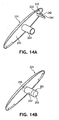
- FIGS. 14A and 14B illustrate two non-limiting examples of coupling mechanisms that may be included on the end caps 221.
- FIG. 14A shows the interior surface 231 of such an end cap 221 including a cross-member plug 223 and a barbed fastener 241.
- the cross-member plug 223 could fit within the cross-member 211 and the barb 242 of the barbed fastener 241 could engage a retention ridge (not shown) present within the mop head 200.
- a finger hole 243 would allow the user to manipulate and disengage the barbed fastener 241 from the retention ridge.
- the end cap of FIG. 14B shows the interior surface 231 of an end cap 221 including a cross-member plug 223 and a quick-release coupling assembly 251.
- the quick-release coupling assembly 251 of the end cap 221 may be the same mechanism as described for coupling assembly 20 of the quick-release handle 10 (as shown in FIGS. 9 , 10 , 11A and 11B ).
- the quick-release coupling assembly 251 could couple the end cap 221 to the cross-member 211 with the detent balls 257 of the coupling assembly 251 engaging a retention stop or recesses within the end of the cross-member 211.
- the user could depress a button 255 that actuates a push rod and head 253 assembly to release the detent balls 257 in a manner similar to that discussed in regard for the coupling assembly 20 of the quick-release handle 10.
- FIGS. 14A and 14B are only two examples of possible coupling mechanism and are not meant to be limiting.
- Other coupling mechanism utilizing the cross-member 211 and/or other components may be possible to releaseably couple the end caps 221 to the mop head 200.
- Coupler shroud 71 Additional stability may be added to the connection of the head mount 161 of the mop head 200 and the coupling assembly 20 by the inclusion of a coupler shroud 71 at the proximal end 16 of the shaft 12. As shown generally in FIGS. 5 and 6 , the coupler shroud 71 has portions that both protect the exposed coupling assembly 20 from damage and cooperate with the designs of the head mounts 161 to securely couple the mop head 200 and handle 10.
- FIGS. 5 and 6 An example of a coupler shroud 71 and cooperating head mount 161 is shown in FIGS. 5 and 6 .
- the illustrated coupler shroud 71 and the head mount 161 are cooperatively designed such that coupler shroud 71 fits within the head mount 161 and the heat mount 161 fits within the coupler shroud 71.
- Such a cooperative design ensures a snug and solid coupling of the mop head 200 attached to the head mount 161 and the handle 10. As such, the mop head 200 would be unable to rotate about the shaft axis. Additionally, such a head mount 161 along with the coupler shroud 71 could help protect the coupling assembly 20 from damage and minimize the contact the coupling assembly 20 has with the outside environment during use.
- a head mount 161 by including a head coupler 75.
- the head coupler 75 connects the head mount 161 to the cross-member 211 of the mop head 200.
- the particular head coupler 75 shown in FIGS. 1 , 5 and 6 has a coupler bracket 79 that fits around a portion of the cross-member 211.
- a coupler spacer 77 cooperates with the coupler bracket 79 to hold the coupler bracket 79 against the support shaft 151.
- a pin 169 through the head mount 161, coupler bracket 79, and the coupler spacer 77 couples the head mount 161 and head coupler 75.
- the head coupler 75 allows the head coupler 75, the attached head mount 161, and the coupled quick-release handle 10 to rotate about the cross-member 211 and consequently allows the distal end 18 of the handle 10 to move vertically relative to the floor and the mop head 200. Additionally, the head coupler 75 is designed to interact with the head mount 161 such that the head mount 161 and coupled handle 10 may pivot on the pin 169 of the head coupler 75 such that the distal end 18 of the handle 10 may be pivoted from side-to-side, relative to the mop head 200.
- any handle coupled to the head mount 161 may be rotated to either side of mop head 200.
- either the front edge 111 or the back edge 113 of the mop head 500 may act as the leading edge of the mop assembly.
- This type of mop head 200 configuration along with a convexly curved lower substrate support surface 203 may help maximize the usage of a coupled disposable cleaning substrate.
- the distal end 18 may be equipped with a grip 41 and a knob 43.
- the grip 41 has a slightly larger diameter than the shaft 12 and is preferably made of material, or is otherwise designed, to facilitate grasping of the shaft 12. Additionally, such a grip 41 should be designed to have the necessary durability required for the typical use of such handle 10.
- the grip 41 may be made of rubber, plastic, metal, or the like. Such materials may be given a texture through processing or through design by the addition of ridges, patterns, or divots to the surface of the grip 41 (as shown in FIGS. 9 , 12A and 12B ).
- the grip 41 may additionally have a knob 43 that also provides the user with more comfort than a traditional stick used with common brooms or mops.
- a traditional stick used with common brooms or mops Generally, such traditional sticks merely have the end rounded off and cause fatigue to the user's hand and often result in blisters or calluses in the palm of the hand after extended use. The small diameter of the end of such traditional sticks causes discomfort and is often difficult for the user to fully grasp.
- a knob 43 such as shown in FIGS. 12A, 12B and 13 , provides the user with a much larger diameter end to the handle 10 compared to traditional sticks.
- the larger diameter of the knob 43, relative to traditional sticks makes the knob 43 much easier to grasp.
- By increasing the surface area of the distal end surface 19 of the knob 43 the forces experienced by the user's hand are spread out over a greater surface area than can be achieved by a rounded end of a traditional stick. Such a better distribution of forces result in a reduction in the amount of fatigue the user experience in their hand.
- the knob 43 may be formed as a unitary part of the terminus of the grip 41 or it may be an additional part added to the distal end 18 of the shaft 12.
- the knob 43 shown in FIGS. 12A, 12B and 13 is only intended to be an exemplary shape for such a knob 43; the knob 43 may be any size and shape, symmetrical or asymmetrical, that allows the user to comfortably grasp and utilize the handle 10.
- the shape of the knob 43 is extended to the grip 41 of the distal end 18 of the handle10.
- This functional grab area 44 of the knob 43 allows a user to maintain a grip of the knob 43, when the user pushes the handle 10 away from their body. This is particularly useful in mopping when a user will regularly "cast out” a mop and then bring the handle 10 and mop back to themselves.
- the button actuator 45 is also present at the distal end 18 of the handle 10. As shown in FIGS. 12A and 13 , the button actuator 45 is incorporated into the knob 43 and is recessed within the distal end surface 19. As such, the user may grasp the knob 43 during use without unintentionally depressing the button actuator 45 and accidentally releasing the mop head 200.
- the button actuator 45 shown in FIGS. 12A, 12B, and 13 is merely the terminus of the push rod 31. However, the button actuator 45 may be a separate piece attached or otherwise operably connected to the push rod 31
- the knob 43 may additionally have the added ability to freely rotate 360-degrees on the terminus of the distal end 18 of the shaft 12. Such a freely-rotating knob 43 would reduce the rubbing and twisting that the user's hand experiences when using traditional sticks. By allowing the knob 43 to freely rotate, the user may maintain a grasp on the knob 43 during regular use of the tool and avoid the fatigue and blisters that often accompanied use of a traditional push broom, mop, or floor duster.
- the rotation of the knob 43 may be accomplished with by any type of mechanical bearings, as are well known, that allow the desired 360-degrees of free rotation.
- the rotation may be accomplished with sliding bearings or bushings, rolling-element bearings (such as ball bearings, roller bearings, taper roller bearings), fluid bearings, magnetic bearings, or the like.
- the rotation of the knob 43 is accomplished with a track of ball bearings 51 that are held in place by cooperative recesses in both the end of the grip 41 and in the knob 43.
- the ball bearings 51 allow the knob 43 to freely-rotate a full 360-degrees about the axis of the shaft 12, on the end of the grip 41.
- FIGS. 12A, 12B and 13 The assembly of the freely-rotating knob 43 is illustrated in FIGS. 12A, 12B and 13 .
- a shaft sleeve 53 is associated with the knob 43 such that the shaft sleeve 53 fits over the push rod 31 when the knob 43 and associated shaft sleeve 53 are inserted into shaft 12.
- a knob-connecting collar 55 inserted into the shaft 12 fits around the shaft collar 53.
- a set screw 57 is inserted from the exterior of the handle 10, through the grip 41, through the shaft 12, and into the knob-connecting collar 55. As such, the set screw 57, holds the knob-connecting collar 55 in place within the interior of the shaft 12.
- the set screw 57 is aligned with a notch 59 circumscribed on the exterior of the shaft sleeve 53. With the set screw 57 in place within the notch 59, the knob 43 is held firmly in place on the terminus of the handle 10 and against the ball bearings 51. As such the knob 43 may freely rotate 360-degrees upon the ball bearings 51, the shaft sleeve 53 is allowed to also freely rotate within the shaft 12, and the knob 43 is kept from being pulled from the end of the handle 10.
- the shaft sleeve 53 has an interior diameter that allows the push rod 31 to pass through the shaft sleeve 53 such that knob 43 and shaft sleeve 53 may freely rotate about push rod 31.
- the button actuator 45 is recessed within the distal end surface 19. When in use, the knob 43 freely rotates about the button actuator 45 and push rod 31 without the risk of the user unintentionally depressing the button actuator 45 or the nonrotating button actuator 45 rubbing on the palm of the user's hand
- the disposable cleaning substrate may be provided in a continuous web format.
- a continuous web format may provide a more conveniently stored than a multitude of individual cleaning substrates.
- the continuous web of substrate could be configured to be a selectable-size substrate 85 such that user need only store one continuous web of substrate rather than multiple sizes of individual substrates.
- the continuous web of selectable-size substrate 85 may have lines of weakness 87 at regular intervals along the length of the web 85.
- Such lines of weakness 87 may be perforations, scoring, areas of weakened material, or other similar character that allows a portion of the cleaning substrate to be removed from the continuous web of substrate 85.
- the regular interval between the lines of weakness 87 would be an interval that would balance the needs of various widths of mop heads 200.
- the system of the present invention may include floor mops having head widths of 12 inches (305mm), 18 inches (457mm), 24 inches (610mm), 36 inches (914mm), and 48 inches (1.2m).
- a selectable-size substrate 85 would preferably have lines of weakness 87 at 6-inch (152mm) intervals. The user would then be able to easily tear off any appropriate length of substrate 85 for the particular width head that they were using.
- Such disposable cleaning substrates may be a single flat sheet as shown in FIG. 15 , a folded or two-ply sheet as shown in FIG. 16 , a tubular substrate, or other formats that could be provided as a continuous web and as necessary for the various mop heads 200 of the system. As shown in FIG. 16 , such substrates may additionally include substrate fasteners 93 that may interact with the particular mop heads 200 to attach the substrate to those mop heads 200.
- the selectable-size substrate shown in FIG. 15 is provided in a roll format 89.
- the roll 89 could be mounted in a roll product dispenser, as are commonly available and widely understood. Such a dispenser could be available on the wall, on a cart, or wherever would be most convenient for the user of the system.
- the selectable-size substrate 85 may be provided to the user in a container 98, such as shown in FIG. 16 .
- the substrate 85 could be stored and dispensed from the container 98 through a dispensing opening 97 in the container 98.
- the substrate 85 may be available in the container 98 in any format that is desired. It may be a roll 89, as in FIG. 15 , merely piled in the container 98, or may be festooned within the container 98.
- the container 98 may have a separator 99 that the user could use to more easily separate the cleaning substrate along the lines of weakness 87.
- Such containers 98 may also include indicia that would help the user identify the amount or type of substrate contained, instructions on proper use, disposal instructions, or other messages that are desired to be conveyed to the user.
- indicia may be any word(s), numeral(s), line(s), symbol(s), picture(s), color(s) and/or combination(s) thereof, that convey the desired message.
- the container 98 may have additional features such as viewing slots such the user can see the amount of remaining substrate, mounting brackets for mounting the container 98 on a support surface, disposal / recycling features, or other such characteristics that enhance the system and make it easier to use.
Landscapes
- Cleaning Implements For Floors, Carpets, Furniture, Walls, And The Like (AREA)
Description
- Various versions of floor mops are commonly available for the variety of cleaning needs in both commercial and domestic consumer environments. For example, cotton string floor dust mops are commonly seen cleaning the dust and debris from school and public building hallways. One problem with such cotton string dust mops is that the dirt and debris can build up in the cotton substrate. Such mop heads need to be regularly cleaned or replaced. Cleaning or replacing the substrate can be cumbersome and may result in significant added cost to the user.
- Smaller versions of such dust mops are readily available for consumer home use and utilize disposable cleaning substrates that are applied to the mop head. The disposable cleaning substrate is most commonly wrapped across the floor-contacting surface of such mop heads and both of the substrate's free ends are fastened to the upper surface of the mop head. Various methods have been used to fasten such substrates to these mop heads including ties, clamps, teeth, screws, and other fasteners.
- In the case of mops using a disposable sponge substrate, the sponge substrate is often held on the mop head by a clamp, a retention bar, a screw, or some other similar fastening mechanism. In one case a cooperative fastener has included on the surface of the sponge and was configured to attach to a fastener on the mop head.
- The problem with any type of fastener used on such mop heads to couple the cleaning substrate to the mop head is that the fastener often wears out, breaks, or becomes fouled with prolonged use. Once the fastener mechanism wears out, breaks or becomes too fouled to be use, the user is forced to purchase a new mop.
- Additionally, the particular fastener used with a particular mop head is often designed for a very specific cleaning substrate and consequently does not fasten other cleaning substrates with the same success, if it can fasten the other cleaning substrate at all. Consequently, most available mop heads that utilize a disposable cleaning substrate require a different mop head be obtained if the user wishes to utilize a different disposable cleaning substrate. This results in increased costs to the user and the user having a collection of mops if they desire to use different cleaning substrates.
- Finally, most mops that use a disposable cleaning substrate fasten the cleaning substrate to the mop head in such a way that a portion of the cleaning substrate is used in the fastener and become available for use in cleaning. Such a use of a portion of the cleaning substrate is an inefficient use of such a cleaning substrate.
- Other problems common with most consumer dry dust or wet mops are related to the design of the mop head. Generally, the handle of such mops are connected at the center of the upper surface of such mop heads. The forces that user applied to the mop head, through the handle, are focused to this connection point; less force is translated to the peripheral edges of the mop head. This problem become exaggerated with larger or more flexible mop heads.
- Additionally, the design of most available consumer dry and wet mops using a disposable cleaning substrate have a flat bottom surface that the substrate is held against. The flat surface ensures a high degree of contact of the cleaning substrate with the surface to be cleaned. However, such a design results in more dust and debris being collected along the front edge of the substrate rather than utilizing the entire substrate surface. As the edges become more soiled the substrate has to be replaced before the central portion of the substrate have been used. Another inefficient use of such a disposable cleaning substrate. A mop head assembly as set out in the first part of claim 1 is known from
US-A-3,996,639 . - As used herein, the term "fasteners" means devices that fasten, join, connect, secure, hold, or clamp components together. Fasteners include, but are not limited to, screws, nuts and bolts, rivets, snap-fits, tacks, nails, loop fasteners, and interlocking male/female connectors, such as fishhook connectors, a fish hook connector includes a male portion with a protrusion on its circumference. Inserting the male portion into the female portion substantially permanently locks the two portions together.
- As used herein, the term "couple" includes, but is not limited to, joining, connecting, fastening, linking, or associating two things integrally or interstitially together.
- As used herein, the term "configure(s)", "configured" or "configuration(s)" means to design, arrange, set up, or shape with a view to specific applications or uses. For example: a military vehicle that was configured for rough terrain; configured the computer by setting the system's parameters.
- As used here, the term "operable" or "operably" means being in a configuration such that use or operation is possible. Similarly, "operably connect(s)" or "operably connected" refers to the relation of elements being so configured that a use or an operation is possible through their cooperation. For example: the machine is operable; the wheel is operably connected to the axle.
- As used herein, the term "hinge" refers to a jointed or flexible device that connects and permits pivoting or turning of a part to a stationary component. Hinges include, but are not limited to, metal pivotable connectors, such as those used to fasten a door to frame, and living hinges. Living hinges may be constructed from plastic and formed integrally between two members. A living hinge permits pivotable movement of one member in relation to another connected member.
- As used herein, the term "substantially" refers to something which is done to a great extent or degree; for example, "substantially covered" means that a thing is at least 95% covered.
- As used herein, the term "alignment" refers to the spatial property possessed by an arrangement or position of things in a straight line or in parallel lines.
- As user herein, the terms "orientation" or "position" used interchangeably herein refer to the spatial property of a place where or way in which something is situated; for example, "the position of the hands on the clock."
- As used herein the terms "nonwoven fabric", "nonwoven material", or "nonwoven web" means a web having a structure of individual fibers or threads which are interlaid, but not in an identifiable manner as in a knitted fabric. Nonwoven fabrics or webs have been formed from many processes such as for example, meltblowing processes, spunbonding processes, and bonded carded web processes. The basis weight of nonwoven fabrics is usually expressed in ounces of material per square yard (osy) or grams per square meter (g/m2 or gsm) and the fiber diameters useful are usually expressed in microns. (Note that to convert from osy to gsm, multiply osy by 33.91).
- As used herein, the term "spunbond", "spunbonded", and "spunbonded filaments" refers to small diameter continuous filaments which are formed by extruding a molten thermoplastic material as filaments from a plurality of fine, usually circular, capillaries of a spinnerette with the diameter of the extruded filaments then being rapidly reduced as by, for example, eductive drawing and/or other well-known spun-bonding mechanisms. The production of spunbonded nonwoven webs is illustrated in patents such as, for example, in
U.S. Pat. No. 4,340,563 to Appel et al. , andU.S. Pat. No. 3,692,618 to Dorschner et al. - As used herein the term "meltblown" means fibers formed by extruding a molten thermoplastic material through a plurality of fine, usually circular die capillaries as molten threads or filaments into converging high velocity gas (e.g. air) streams which attenuate the filaments of molten thermoplastic material to reduce their diameter, which may be to microfiber diameter. Thereafter, the meltblown fibers are carried by the high velocity gas stream and are deposited on a collecting surface to form a web of randomly dispersed meltblown fibers. Such a process is disclosed, in various patents and publications, including NRL Report 4364, "Manufacture of Super-Fine Organic Fibers" by B. A. Wendt, E. L. Boone and D.D. Fluharty; NRL Report 5265, "An Improved Device For The Formation of Super-Fine Thermoplastic Fibers" by K.D. Lawrence, R. T. Lukas, J. A. Young; and
U.S. Patent No. 3,849,241, issued November 19, 1974, to Butin , et at. - As used herein "multilayer laminate" means a laminate wherein one or more of the layers may be spunbond and/or meltblown such as a spunbond/meltblown/spunbond (SMS) laminate and others as disclosed in
U.S. Patent 4,041,203 to Brock et al. ,U.S. Patent 5,169,706 to Collier, et al ,US Patent 5,145,727 to Potts et al. ,US Patent 5,178,931 to Perkins et al. andU.S. Patent 5,188,885 to Timmons et al. Such a laminate may be made by sequentially depositing onto a moving forming belt first a spunbond fabric layer, then a meltblown fabric layer and last another spunbond layer and then bonding the laminate in a manner described below. Alternatively, the fabric layers may be made individually, collected in rolls, and combined in a separate bonding step. Such fabrics usually have a basis weight of from about 0.1 to 12 osy (6 to 400 gsm), or more particularly from about 0.40 to about 3 osy. Multilayer laminates for many applications also have one or more film layers which may take many different configurations and may include other materials like foams, tissues, woven or knitted webs and the like. - These terms may be defined with additional language in the remaining portions of the specification.
- The invention is characterised as set out in claim 1. The disposable substrate mop can accommodate different fasteners and easily replace those fasteners when worn, to accommodate different substrates, and increase the longevity of the substrate mop. In one embodiment the mop head design effectively distributes forces applied to mop head through a mop handle. Preferably, the area of unused cleaning substrate be minimized and the usage of the entire cleaning substrate be maximized.
- The present invention is directed to a mop head assembly for use with a handle and a cleaning substrate. The mop head assembly includes a lower substrate support surface, at least one fastener channel associated with the lower substrate support surface, and fastener strips that can be inserted into to fastener channel. Such a fastener strip is configured to couple the lower substrate support surface to a cleaning substrate.
- In various embodiments, more than one fastener channel may be present on the lower substrate support surface, multiple fastener strips may be present in the same fastener channel. More than one type of fastener strip are used. In other various embodiments, the lower substrate support surface is convexly curved, an end cap is releaseably attached to the end of the lower substrate support surface, and the end cap may include an brush, scrubbing tool, or rounded shape.
- In other embodiments, the assembly may include an upper surface. That upper surface may additionally include a secondary substrate attachment point. Such a secondary attachment point may be a fastener channel and fastener strip.
- In some embodiments, the assembly may include a mop handle releaseably engaged with a socket mount on the mop head assembly. The mop handle may be a quick-release handle including a proximal end proximate to the mop head and a distal end distal to the mop head; a quick-release coupling assembly positioned on the proximate end of the handle, the quick-release coupling assembly configured to releaseably couple the handle to the head mount; and a button actuator positioned on the distal end of the handle, the button actuator operably connected to the quick-release coupling assembly. Additionally, in various embodiments, the handle may additionally include a coupler shroud that cooperatively couples with the head mount, the button actuator may be recessed within the end of the shaft, and the handle may include an ergonomic, freely-rotating knob.
- The present invention is also directed to a mop head assembly as described above, but also including a cross-member associated with the lower substrate support surface. The cross-member extending between the opposing end edges of the lower substrate support surface and where the cross-member is configured such that forces applied to a central portion of the cross-member are distributed along the cross-member toward the end edges of the lower substrate support surface.
- The system includes a plurality of fastener strips. That plurality of fastener strips may include a variety of different types of fastener strips and may include an indicia. Additionally the system may include a variety of different types of cleaning substrates which may include an indicia.
-
-
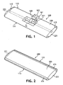
FIG. 1 is a perspective view of a mop head of the present invention; -
FIG. 2 is a perspective view of a lower substrate support surface of the mop head ofFIG. 1 , showing the fastener channels on the lower substrate support surface; -
FIG. 3 is a partial perspective view of the lower substrate support surface of the mop head ofFIG. 1 , showing the fastener channel and a fastener strip; -
FIG. 4 is a perspective view of lower substrate support surface of the mop head ofFIG. 1 , showing another fastener channel configuration; -
FIG. 5 is a partial perspective view of the mop head ofFIG. 1 shown coupled with a quick-release handle and illustrating a disposable cleaning substrate being coupled to the mop head, the disposable cleaning substrate shown being wrapped across the lower substrate support surface and using secondary attachment structures on the upper surface of the mop head to assist in securing the cleaning substrate; -
FIG. 6 is a partial perspective view of the mounting head of the mop head ofFIG. 1 , the mounting head positioned to engage the coupling assembly of the quick-release handle; -
FIG. 7 is a partial perspective exploded view of an end cap of the mop head ofFIG. 1 ; -
FIG. 8A is a perspective view of a rounded end cap that may be used with the mop head ofFIG. 1 ; -
FIG. 8B is a perspective view of a brush end cap that may be used with the mop head ofFIG. 1 ; -
FIG. 8C is a perspective view of a scrubber end cap that may be used with the mop head ofFIG. 1 ; -
FIG. 9 is a perspective view of a quick-release handle; -
FIG. 10 is a partial perspective exploded view of a quick-release coupling assembly of the handle ofFIG. 9 ; -
FIG. 11A is a cross-sectional view of a quick-release coupling assembly of the handle ofFIG. 9 taken along line 11-11, shown in an engaged configuration with a generic socket mount (illustrated by phantom lines); -
FIG. 11B is a cross-sectional view of the quick-release coupling assembly of the handle ofFIG. 9 taken along line 11-11, shown in a release configuration in relation to the generic socket mount (illustrated by phantom lines); -
FIG. 12A is a partial perspective view of the distal end of the quick-release handle ofFIG. 9 showing a grip, a freely-rotating knob, and a button actuator; -
FIG. 12B is a partial perspective exploded view of the distal end of the quick-release handle ofFIG. 12A ; -
FIG. 13 is a cross-sectional view of the distal end of the quick-release handle ofFIG. 12A taken along the line 13-13; -
FIG. 14A is a perspective view of the inside surface of an end cap including a barbed fastener; -
FIG. 14B is a perspective view of the inside surface of an end cap including a quick-release coupling assembly and showing a button (by dotted lines) that actuates the quick-release coupling assembly; -
FIG. 15 is a perspective view of a continuous web of selectable-width cleaning substrate in a roll format; and -
FIG. 16 is a perspective view of a continuous web of selectable-width cleaning substrate and disposed within a container. - Reference will now be made in detail to one or more embodiments of the invention, examples of which are illustrated in the drawings. Each example and embodiment is provided by way of explanation of the invention, and is not meant as a limitation of the invention. For example, features illustrated or described as part of one embodiment may be used with another embodiment to yield still a further embodiment. It is intended that the invention include these and other modifications and variations as coming within the scope of the invention.
- Referring to
FIGS. 1 - 8C in general, themop head 200 of the present invention includes a lowersubstrate support surface 203 to which a disposable cleansing substrate may be coupled during use of themop head 200. One ormore fastener channels 171 may be associated with the lowersubstrate support surface 203 and may be configured to contain one or more fastener strips 181. Such fastener strips 181 may be configured to couple the lowersubstrate support surface 203 to the disposable cleansing substrate. - As shown in
FIG. 1 , themop head 200 may also include across-member 211. The cross-member 211 spans the width of themop head 200, from oneend edge 115 to theopposite end edge 115. Also, the cross-member 211 would desirably be centrally positioned between, and runs generally parallel to, thefront edge 111 and theback edge 113 of themop head 200. - The cross-member 211 is configured with the
mop head 200 to bring all of the elements of the mop into cooperation. Ahead mount 161 may be coupled to the cross-member at a central position on the cross-member 211 between the opposed end edges 115; thehead mount 161 configured to releaseably couple themop head 200 with a handle. The cross-member 211 is intended to be coupled to themop head 200 in such a way that the cross-member 211 is in working communication with the lowersubstrate support surface 203. - For example, the cross-member 211 partially illustrated in
FIG. 7 is secured to theend edge 115 of the lowersubstrate support surface 203 by across-member collar 213. One or more ofsuch collars 213 may be included along thewidth mop head 200 to better couple the cross-member 211 to the lowersubstrate support surface 203. The configuration illustrated inFIG. 7 is only one possible configuration of how the cross-member 211 may be coupled to themop head 200; the cross-member 211 may be coupled to themop head 200 by any means or fashion that the cross-member 211 is working communication with the lowersubstrate support surface 203. - In use, the
mop head 200 may be coupled with ahandle 10 and a disposable cleaning substrate 83, as illustrated inFIG. 5 . When the user pushes on thehandle 10 to clean a surface with the attachedmop head 200, the forces applied to thehandle 10 are communicated through thehead mount 161, through the cross-member 211, and across the width of the lowersubstrate support surface 203. By translating the forces applied to the centrally located handle 10 to the entire width of the lowersubstrate support surface 203 of themop head 200, the user is able to apply pressure across the entire width of themop head 200. Resultantly, the user may make better use the entirelower substrate surface 203 to clean the floor, or other surface the mop is being used to clean. - The cross-member 211 is preferably hollow to better couple with
end caps 221 having a cross-member plug 223 (seeFIG. 7 ) and to decrease the weight of themop head 200. The thickness of thehollow cross-member 211 is a function of the materials used to make the cross-member 211, the inside diameter required to accommodate a particularcross-member plug 223, and the strength and weight desired. One skilled in the art would see how such variables could be balanced to produce the cross-member 211. - The cross-member 211 may be made from any material that meets the needs of the
particular mop head 200. For example, astronger cross-member 211 may be desired for commercial applications while alighter cross-member 211 may be desired for home applications. Other considerations may include, but are not limited to, weight, durability, compatibility with chemicals and substances themop head 200 may come in contact, appearance, ease of cleaning, colors available, disposability, and the like. Typically, the cross-member may be made of a metal, plastic, or wood. More particularly, the cross-member 211 may be made of aluminum, stainless steel, ABS-plastic, or the like. Again, one skilled in the art would see how such variables could be balanced to produce the cross-member 211. - As shown in
FIGS. 1 and 2 , themop head 200 is generally rectangular in shape with a side-to-side width (the distance between the end edges 115 of the mop head 200) greater than its front-to-back depth (the distance between thefront edge 111 and theback edge 113 of the mop head 200). However, themop head 200 may be any size and shape, symmetrical or asymmetrical that is desired for the particular cleaning needs being addressed. Generally, themop head 200 may have a side-to-side width of between about 10 inches (254mm) and about 72 inches (1.8m) and a front-to-back depth of between about 4 inches (102mm) and about 16 inches (406mm), though other sizes are possible. By way of non-limiting example, amop head 200 intended for commercial use may have a width of about 48 inches (1.2m) and a depth of about 12 inches (305mm), while amop head 200 intended for domestic use may have a width of about 10 inches (254mm) and a depth of about 6 inches (152mm). The dimensions of themop head 200 may be any width and depth that is desired to meet the particular cleaning application. - As illustrated in
FIGS. 1 and 2 , the lowersubstrate support surface 203, theupper surface 205, and the end caps 221 are slightly convexly curved between thefront edge 111 and theback edge 113 of themop head 200. Resultantly, the cross-sectional profile of themop head 200 is generally oblate in shape, however other shapes, symmetrical and asymmetrical, are possible. Thus the thickness of themop head 200 may vary between the front and back of themop head 200. Generally, themop head 200 may have a thickness between about 0.5 inches (12.2mm) and about 2 inches (50.8mm) in the center and be thinner at both thefront edge 111 andback edge 113, though other sizes and cross-sectional profiles are possible. - The lower
substrate support surface 203 maybe made from any material that meets the needs of theparticular mop head 200. For example, the lowersubstrate support surface 203 may be desired for commercial applications may utilize a heavier and/or stronger material, while a lighter material may be desired for home applications. Other considerations may include, but are not limited to, weight, durability, compatibility with the cleaning substrate(s) to be used, compatibility with chemicals and substances thesurface 203 may come in contact, appearance, ease of cleaning, colors available, disposability, and the like. Typically, the lowersubstrate support surface 203 may be made of a metal or plastic. More particularly, the lowersubstrate support surface 203 may be made of aluminum, stainless steel, ABS-plastic, or the like. One skilled in the art would see how such variables could be balanced to produce the lowersubstrate support surface 203. - Typically, as shown in
FIGS. 1 and5 , themop head 200 may also include anupper surface 205. Such anupper surface 205 may be separate surface mated to the lowersubstrate support surface 203, may be the opposite size of the lowersubstrate support surface 203, or may be one surface of a singular tubular shape, opposite and in opposition to the lower substrate support surface 203 (as is shown inFIGS. 1 and5 ). As such, theupper surface 205 may be made of the same material as the lowersubstrate support surface 203 or may a made of a different material. One skilled in the art would see how the same variables balance in the construction of the lowersubstrate support surface 203 could be balanced for theupper surface 205. - As illustrated in
FIGS. 1, 2 ,4 ,5 , and7 , themop head 200 of the present invention may also include a pair ofend caps 221 coupled to either endedge 115 of themop head 200. The end caps 221 may be desirable to keep the fastener strips 181 within anyfastener channels 171 extending from theend edge 115 of themop head 200. The end caps 221 are desirably configured to be releaseably coupled to theend edge 115 such that theend cap 221 may be removed from theend edge 115 when afastener strip 181 is to be removed or inserted into thefastener channel 171, and then re-coupled to theend edge 115. As shown inFIG. 7 , theend cap 221 may include anend cap grip 225 by which the user may grasp theend cap 221 when removing theend cap 221 from or replacing theend cap 221 on to themop head 200. - The end caps 221 may be cooperatively shaped to easily couple with the lower
substrate support surface 203, and theupper surface 205. As shown inFIGS. 1, 2 ,4 ,5 and7 , the end caps 221 may have an edge that is convexly curved to match the curve of the lowersubstrate support surface 203. Theend cap 221 may be coupled to themop head 200 by any method or means that would allow theend cap 221 to removed and replaced in order to insert fastener strips 181, while remaining securely in place on themop head 200 when themop head 200 is in use. - As shown in
FIG. 7 , theend cap 221 may be secured to themop head 200 with anend cap fastener 227 the works cooperatively with a coupler on themop head 200. Additionally, across-member plug 223 may be included on theend cap 221 to work cooperatively with a cross-member 211. Alternatively, theend cap 221 may be fastened to themop head 200 by friction fit into theend edge 115 of themop head 200. Other types of fastening methods and fasteners are known and could be used to releaseably couple the end caps 221 to themop head 200. - Additionally, the
end cap 221 may provide additional functionality to themop head 200. As shown inFIGS. 8A, 8B and 8C , various shapes, tools or other items may be included with theend cap 221. In the example ofFIG. 8A , theend cap 221 may include arounded end cap 191 that may help prevent themop head 200 from scraping walls or other surfaces while using the mop. In the example ofFIG. 8B , theend cap 221 may include abrush end cap 193. In the example ofFIG. 6C , thefixed end cap 221 may include a scrubbing edgedend cap 195 having ridges made of a scrubbing material (e.g., rubber, plastic, sponge). Such examples are not intended to be limiting; one skilled in the art could see how other items could be incorporated into anend cap 221 to add functionality to themop head 200. - As discussed above, the lower
substrate support surface 203 and the end caps 221 may be convexly curved from thefront edge 111 to theback edge 113 of themop head 200. Traditional dry dust mops, disposable cleaning substrate mops, and sponge mops typically have a flat surface that contacts the surface to be cleaned (i.e., a floor). Such a flat-contacting surface maximizes the contact of the mop head or substrate with the floor, however, dust, dirt and debris tends to pile up at the edges of such mops, leaving the central portion of the mop or substrate unused. By providing a slight convex curve to the lowersubstrate support surface 203 of the present invention, a greater percentage of the entire cleaning substrate surface may be used. - The
mop head 200 of the present invention is intended to be used with a disposable cleaning substrate 83. Such cleaning substrates are widely available and well understood. Typically such substrates may be woven, nonwoven, laminates, composites, or combinations thereof, and may be made from natural fibers, synthetic fibers, or combinations thereof. By way of non-limiting examples, the disposable cleaning substrate may be a spunbonded polypropylene material, a knitted polyester substrate, a microfiber substrate made with a polyester/polyamide yam, a stabilized open-cell thermoplastic foam laminate, a hydroentangled nonwoven composite material, a sponge substrate, or other such substrates as may be desired for particular cleaning needs. - Additionally, such cleaning substrates may be provided as a dry substrate or as a saturated substrate. The cleaning substrate may include additional substances such as cleansers, disinfectants, sanitizers, fragrances, or the like. The disposable cleaning substrate may also be electric treated to impart a static electric charge to the material to attract dust to the charged substrate. Similarly, the disposable cleaning substrate may be made from particular materials (such as rubber, spunbonded polypropylene, spunlace fabrics, or combinations thereof) that may develop such a static electric charge during it use on particular surfaces.
-
FIGS. 2 ,3 and 4 illustrate thefastener channels 171 that are included on themop head 200 of the present invention. Thefastener channels 171 are associated with the lowersubstrate support surface 203 to couple a disposable cleaning substrate to themop head 200.Such fastener channels 171 extend from the end edges 115 of themop head 200 so that fastener strips 181 may be easily inserted into thefastener channels 171. As seen inFIG. 2 , thefastener channels 171 are preferably located near thefront edge 111 andback edge 113 of the lowersubstrate support surface 203 and extend generally parallel tosuch edges - As seen in
FIG. 3 , thefastener channel 171 may be configured is such a way as to securely retain thefastener strip 181 within thechannel 171 while allowing theparticular fastener 185 of thestrip 181 to extend out of the plane of the lowersubstrate support surface 203 to engage a disposable cleaning substrate. Typically, as shown inFIG. 3 , thefastener strip 181 includes afastener 185 and abacking 183 that secures thefastener 185 to thestrip 181. Thebacking 183 additionally provides some degree of rigidity to thefastener strip 181, such that thefastener strip 181 is not easily pulled out of thefastener channel 171 by any manner other than from theend edge 115 of themop head 200. - The
fastener 185 present on thefastener strip 181 may be any fastener attached to abacking strip 183 that is compatible with the particular cleaning substrate material to be affixed to themop head 200. The fasteners may be appropriate to directly attach to the substrate material or they may cooperatively couple with a substrate fastener 93 (seeFIG. 16 ) included on the cleaning substrate. Non-limiting examples of such fasteners that may be used with the fastener strips 181 may include independent fasteners such as hook fasteners (as shown inFIG. 4 ), pressure-sensitive adhesives, and the like, as well as cooperative fasteners such as hook-and-loop fasteners, snaps, magnets, buttons, and the like. - Additionally, different types of fastener strips 181, each utilizing a different type of
fastener 185, are provided to accommodate a variety of different disposable cleaning substrates that the user may want to utilize. For example, a fastener strip having an adhesive fastener may be provided for a cleaning substrate laminate having a film backing layer, a fastener strip having a hook fastener may be provided to accommodate a spunbonded polypropylene cleaning substrate, and a more tenacious hook fastener may be provided on yet another fastener strip to accommodate a microfiber cleaning substrate intended for more vigorous cleaning. One skilled in the art would understand that different types of fasteners work better with different types of substrates and would be able to provide an appropriate variety of fastener strips to accommodate the substrates that a user intends to utilize. - The
mop head 200 illustrated inFIG. 2 shows twofastener channels 171 that extend across the entire width of themop head 200 and asingle fastener strip 181 may be present in each of thefastener channels 171. However, other combinations of fastener strips 181 andfastener channels 171 are possible. For example, for themop head 200 shown inFIG. 2 , one type offastener strip 181 may be used in thefastener channel 171 next to thefront edge 111 and a different type offastener strip 181 may be used in thefastener channel 171 next to theback edge 113 of themop head 200. - In another example, multiple shorter fastener strips 181 may occupy the same fastener channel. In such instances, the multiple fastener strips 181 may all utilize the same type of fastener or they may include fastener strips 181 utilizing different types of fasteners. Additionally, the multiple fastener strips 181 may be inserted in the
fastener channel 171 in such a way that they are in contact with one another or they may be separated by a channel spacer 175 (seeFIG. 4 ) that is inserted into thefastener channel 171 between such fastener strips 181. -
FIG. 4 illustrates another possible configuration of fastener channels. As shown, combinations oflong fastener channels 171 may be used in combination withpartial fastener channels 173. BothFIGS. 2 and4 illustratefastener channels 171 near the front andback edges mop head 200. However, thefastener channels 171 may also, or may alternatively, be present on thefront edge 111, theback edge 113, and/or included on theupper surface 205. - Additionally, one or more
secondary attachment structures 207 may be present on theupper surface 205 to assist the fastener channel(s) 171 to retain the disposable cleaning substrate 83 during use of themop head 200. As shown inFIG. 5 , the asecondary attachment structure 207 may be a toothed structure that grasps substrate 83 pushed into its teeth. Othersecondary attachment structures 207 are possible and may include one or more different types of attachment structures. Thesecondary attachment structure 207 may be anotherfastener channel 171 including afastener strip 181. Other non-limiting examples ofsuch attachment structures 207 may include pressure sensitive adhesives, clips, screws, clamps, hook fasteners, or other such fasteners as are well known. - One skilled in the art would be able to understand that various combinations of
fastener channel 171 configurations (including the position, length and number of such channels), fastener strips 181 (including length, fastener types and number of such strips), and secondary attachment structures 207 (including types, position, and number of such structures) could be configured to couple a particular disposable cleaning substrate 83 to themop head 200. It is also understood how alternate configurations would be appropriate for other types of cleaning substrates. - A cleaning system including such a
mop head 200 may be provided to the user to meet their varied cleaning needs. The user could be supplied with a plurality of disposable cleaning substrates including different types of substrates that may be appropriate for different cleaning needs. Additionally, the user could be supplied with a variety of fastener strips of different types and sizes that are configured to work with the variety of disposable cleaning substrates supplied. To help the user determine the best substrates for their particular cleaning needs, instructions could also be provided to the user. The instruction may also provide the user with best fastener strip or combination of fastener strips to be used for a particular substrate. - Additionally, the each of the plurality of disposable cleaning substrates and each of the fastener strips may include indicia that would help differentiate between the various substrates, differentiate between the various substrates, help match fastener strips with the appropriate cleaning substrates, or other messages that are desired to be conveyed to the user. Such indicia may be any word(s), numeral(s), line(s), symbol(s), picture(s), color(s) and/or combination(s) thereof, that convey the desired message. By way of non-limiting example, cleaning substrates and the fastener strips that work best with those substrates may include matching symbols or may be the same color. Instructions may also be included to help the user understand the various indicia used and / or help them match specific substrates, fastener strips, or characteristic traits with specific indicia.
- The
mop head 200 of the present invention may be included as part of a mop system that also includes a handle configured to be coupled to thehead mount 161. Such a handle may be a traditional mop stick, as are well known, having a conventional threaded tip that screws into thehead mount 161 or some other similar common coupling mechanism. However, it is preferred that the handle of the mop system be a quick-release handle 10 that allows the user to disengage thehandle 10 from themop head 200 without having to bend over, reposition the mop, or otherwise come in close contact with the potentiallydirty mop head 200. - Referring to
FIGS. 9 to 13 in general, such a quick-release handle 10 may include anelongated shaft 12 having two opposite ends; aproximal end 16 and adistal end 18. Theproximal end 16 is proximate to themop head 200 to which thehandle 10 is to be attached. Thedistal end 18 is distal to theproximal end 16 and proximate to the user. Theproximal end 16 includes the quick-release coupling assembly 20 that will cooperate with and couple thehandle 10 to amop head 200. Theproximal end 16 is also considered as the attachment end of thehandle 10 and the terms "proximal end" and "attachment end may be used interchangeably. - Generally, the
distal end 18 will have agrip 41 by which the user may grasp thehandle 10. Thedistal end 18 is also considered the grip end of thehandle 10 and the terms "distal end" and "grip end" may be used interchangeably. Additionally, thedistal end 18 accommodates thebutton actuator 45 which the user depresses to release thecoupling assembly 20 from anymop head 200 that may be coupled with theproximal end 16 of thehandle 10. Thus, the user can release amop head 200 from thehandle 10 by manipulating thedistal end 18 rather than repositioning the handle, bending over, or going anywhere near the potentially dirtyproximal end 16 of the tool. - The
elongated shaft 12 is shown inFIG. 9 as generally cylindrical in shape, having a circular cross-section, as is common for most commonly available long tool handles. As such, theelongated shaft 12 has a singleperipheral surface 14. However, other cross-sectional shapes are contemplated and are considered within the scope of the present invention. By way of non-limiting examples, the cross-sectional shape of theelongated shaft 12 may be elliptical, polygonal, or any other symmetrical or asymmetrical shape. Any such alternative cross-sectional shape may provide theelongated shaft 12 with additionalperipheral surfaces 14. - Generally, it is desired that the
elongated shaft 12 have a length of about 36 inches (0.9m) to about 72 inches (1.8m). For a quick-release handle 10 for use with cleaning tool mop heads 200, the elongated shaft will preferably be about 5 feet (1.5m) in length, similar to the length of commonly available tool handles. Theelongated shaft 12 should have an outside diameter suitable for the intended tool mop heads 200 and that is comfortable for use by range of user hand sizes. Typically, the outside diameter will be in the range of about 0.5 inches (12.7mm) to about 1.5 inches (38.1 mm). Preferably, the outside diameter of theshaft 12 will be similar to that of commonly available handles, 0.75 inches (19.1mm). Also, theshaft 12 illustrated inFIG. 9 is generally uniform in its diameter from theproximal end 16 to thedistal end 18. However, theshaft 12 may alternatively have a nonuniform diameter along its length and may have sections of uniform and nonuniform diameter along its length. - The
elongated shaft 12 is hollow to accommodate thepush rod 31 and the other associated elements of thebutton actuator 45 and quick-release coupling assembly 20. The hollowed nature of theshaft 12 also decreases the weight of thehandle 10 and the amount of material used in making thehandle 10. The thickness of the hollow elongatedshaft 12 is a function of the materials used to make theshaft 12, the inside diameter required to accommodate the elements to be accommodated within theshaft 12, and the strength and weight desired. One skilled in the art would see how such variables could be balanced to produce the desiredshaft 12. - The
elongated shaft 12 may be made from any material that meets the needs of thevarious mop heads 200 with which such ahandle 10 is expected to be used. For example, astronger shaft 12 may be desired for commercial applications while a lighter shaft may be desired for home applications. Other considerations may include, but are not limited to, weight, durability, compatibility with chemicals and substances the handle may come in contact, appearance, ease of cleaning, colors available, disposability, and the like. Typically, theshaft 12 may be made of a metal, plastic, or wood. More particularly, theshaft 12 may be made of aluminum, stainless steel, ABS-plastic, or the like. Again, one skilled in the art would see how such variables could be balanced to produce the desiredshaft 12. - Additionally, designs in which the
shaft 12 is telescoping, collapsible, and/or foldable are also considered to be within the scope of the present invention. - As discussed above, the quick-
release coupling assembly 20 is positioned on theproximal end 16 of thehandle 10 and is configured to be coupled with amop head 200. Thecoupling assembly 20 may utilize any releasable coupling mechanism, as are well known, to releaseably couple with amop head 200. By way of non-limiting examples, such a releasable coupling mechanism may utilize a detent ball assembly (as illustrated inFIGS. 10 ,11A and 11B ), a collet, a chuck, a clamping spring, a bayonet mount, a barbed fastener, a ribbed shank clip fastener, or other such mechanisms or any combination thereof. - The mechanism of the
coupling assembly 20 is actuated by the user pressing and releasing thebutton actuator 45 on thedistal end 18 of theshaft 12. Thebutton actuator 45 is operably connected with thecoupling assembly 20 by thepush rod 31 which extends along the length of theshaft 12, from thebutton actuator 45 to thecoupling assembly 20. As can be seen in the example illustrated inFIGS. 10 ,11 A ,11 B ,12A, 12B and 13 , thebutton actuator 45 is the terminus of thepush rod 31 on thedistal end 18 of thehandle 10. At the proximal end of thepush rod 31, astop collar 33 is fitted around and attached to pushrod 31 by apin 34. Aspring 35 around thepush rod 31 and compressed between thestop collar 33 and the end wall of the steppedtip 21 of thecoupling assembly 20 keeps thepush rod 31 biased toward thedistal end 18. - As shown in
FIGS. 10 ,11 A, and 11B , thecoupling assembly 20 at theproximal end 16 of theshaft 16 includes a steppedtip 21 having afirst end 711 inserted into theproximal end 16 of theshaft 12 and asecond end 719 that extends from the end of theshaft 12 and into thesocket mount 63 of ahead mount 61 of a working head ormop head 200 to which thehandle 10 is to be coupled. The steppedtip 21 has an internal longitudinal channel 22 that extends the length of the steppedtip 21, from thefirst end 711 to thesecond end 719. Thefirst section 712 of the steppedtip 21 near thefirst end 711 has a diameter slightly smaller than the inside diameter of theshaft 12 such that the steppedtip 21 may be snuggly fit into theproximal end 16 of theshaft 12. Alip section 714 of the steppedtip 21 seats the steppedtip 21 in theproximal end 16 of theshaft 12 and prevents the steppedtip 21 from being pushed further into theshaft 12. - As illustrated in
FIGS. 11A and 11B , once the steppedtip 21 is installed in theshaft 12, thepush rod 31 extends into the longitudinal channel 22 of the steppedtip 21. Astop rod 23 extends from the proximal end of thepush rod 31 and is attached to the end of thepush rod 31. Thestop rod 23 extends out of the longitudinal channel 22 at thesecond end 719 of the steppedtip 21 and is capped by ahead portion 25. Thehead portion 25 has aconical portion 26 that extends around thestop rod 23 inside the longitudinal channel 22. When thestop rod 23 is attached to both thepush rod 31 and thehead portion 25, thespring 31 that biases thepush rod 31 toward the distal end 18 (as discussed above) also pulls thehead portion 25 against thesecond end 719 of the steppedtip 21. - The
third section 718 of the steppedtip 21 additionally includesports 29 that extend from the longitudinal channel 22 to the outer surface of the steppedtip 21. Asingle detent ball 27 is retained by eachport 29 and against thestop rod 23 or theconical portion 26. - When the
handle 10 andcoupling assembly 20 are in the engaged configuration, such as shown inFIG. 11A , thespring 35 between thestop collar 33 and thefirst end 711 of the steppedtip 21 biases thepush rod 31 toward thedistal end 18 of theshaft 12. Thestop rod 23 attached to both thehead portion 25 and thepush rod 31 is subsequently pulled into contact with thesecond end 719 of the steppedtip 21. Thehead portion 25 is only pulled to thesecond end 719 and thus thespring 35 cannot push thepush rod 31 further toward thedistal end 18 or pull the stop rod further into the steppedtip 21. In such an engaged configuration, thecoupling assembly 20 and pushrod 31 are held in a neutral state by thespring 35. - As shown in
FIG. 11A , when thecoupling assembly 20 is in the engaged state, thehead portion 25 is pulled to thesecond end 719 of the steppedtip 21 such that theconical portion 26 of thehead 25 is pulled into the longitudinal channel 22. Theconical portion 26 engages thedetent balls 27 and pushes them into theports 29 such that the detent balls partially extend outside of the exterior wall of thethird section 718 of the steppedtip 21. -
FIG. 11 B illustrates the release configuration of thehandle 10 andcoupling assembly 20. When the user depresses thebutton actuator 45 at thedistal end 18, thepush rod 31 and thestop collar 33 is pushed toward theproximal end 16 of theshaft 12, compressing thespring 35 between thestop collar 33 and thefirst end 711 of the steppedtip 21. Thestop rod 23, including thehead 25, is consequently pushed away from thesecond end 719 of the steppedtip 21. As theconical portion 26 of thehead 25 is pushed toward thesecond end 719, thedetent balls 27 are allowed to fall back into the longitudinal channel 22 and against thestop rod 23. When the user releases thebutton actuator 45, thespring 35 returns thehandle 10 to the engaged, or neutral, configuration as illustrated inFIG. 11A . - To work with the
coupling assembly 20, thegeneric head mount 61 includes asocket mount 63 into which thecoupling assembly 20 may be inserted. Aretention stop 65 within thesocket mount 63 cooperatively engages with thecoupling assembly 20 to securely couple the working head and the quick-release handle 10. Such aretention stop 65 may be anything within thesocket mount 63 that cooperatively engages thedetent balls 27 of thecoupling assembly 20. By way of non-limiting examples, theretention stop 65 may be a ring fixed within the socket mount 63 (as shown inFIGS. 11 A and 11 B ), recesses within the wall of thesocket mount 63, holes in the socket mount 63 (as shown inFIG. 9 ), or another configuration which can engage thedetent balls 27. - In operation, when the
coupling assembly 20 is inserted into thesocket mount 63, the steppedtip 21 would proceed from the mouth of thesocket recess 67 toward therecess terminus 67. When thecoupling assembly 20 is in the engaged (neutral) configuration, thedetent ball 27 are pushed out of theports 29 by theconical portion 26 of thehead 25, as discussed above. The inside diameter of the ring used as theretention stop 65 shown inFIGS. 11A and 11 B is designed to be slightly larger than the outer diameter of thethird portion 718 of the steppedtip 21. Thus, as the steppedtip 21 is inserted into thesocket mount 63, thethird portion 718 snugly passes into theretention stop 65, but the protrudingdetent balls 27 will come into contact with theretention stop 65. As the user continues to apply insertion pressure to the steppedtip 21, thedetent balls 27 are forced into theports 29 and push against theconical portion 26 and consequently push thehead 25 from thesecond end 719. Once the steppedtip 21 is pushed farther into thesocket mount 63, thedetent balls 27 clear theretention stop 65 and are again forced out of theports 29 by theconical portion 26. Thedetent balls 27 engage theretention stop 65 as illustrated in the engaged configuration shown inFIG. 11A . - The
socket mount 63 includes asocket recess 67 on the recess terminus side of theretention stop 65. Such arecess 67 allows enough room for thehead 25 to extend from steppedtip 21 as necessary for thedetent balls 27 to drop inside the steppedtip 21 during insertion of thecoupling assembly 20 or release of the working head, as discussed above. - The use of a
coupling assembly 20 with thedetent ball 27 mechanism described and illustrated inFIGS. 10 ,11A and 11 B , is only onepossible coupling assembly 20 that may be used in thehandle 10 of the present invention. As discussed above, other coupling mechanisms are contemplated for thecoupling assembly 20 to couple thehandle 10 with amop head 200 and operably connect to thebutton actuator 45 such that themop head 200 is released from thehandle 10 when thebutton actuator 45 is manipulated. - For increased universality, the
socket mount 63 may additionally be threaded from the mouth of thesocket mount 63 to theretention stop 65. Such asocket mount 63 could then also accept a standard handle with a thread tip, if the user so desired. - The
second section 716 of the steppedtip 21 is designed to have an outside diameter slightly smaller than the inside diameter of thesocket mount 63. This ensures that thecoupling assembly 20 snuggly fits within thesocket mount 63 such that themop head 200 is securely and solidly held at the end of thehandle 10. If thesocket mount 63 is threaded, thesecond section 716 would need to have an outside diameter slightly smaller that the threads.
Although not shown, a second spring could be included inside of thesocket mount 63, attached to therecess terminus 69. Such a spring would be compressed upon insertion of thecoupling assembly 20 into thesocket mount 63. When thebutton actuator 45 was subsequently pressed to release the working head from thehandle 10, such a spring would then bias thesocket mount 63 off of thecoupling assembly 20. - Returning briefly to the end caps 221 of the
mop head 200,such end caps 221 may be releaseably coupled to theend edge 115 of the mop head using similar coupling mechanism as discussed for thecoupling assembly 20 of thehandle 10.FIGS. 14A and 14B , illustrate two non-limiting examples of coupling mechanisms that may be included on theend caps 221.FIG. 14A shows theinterior surface 231 of such anend cap 221 including across-member plug 223 and abarbed fastener 241. When such aend cap 221 is coupled with theend edge 115 of themop head 115, thecross-member plug 223 could fit within thecross-member 211 and thebarb 242 of thebarbed fastener 241 could engage a retention ridge (not shown) present within themop head 200. When the user wished to release theend cap 221 ofFIG. 14A from themop head 200, afinger hole 243 would allow the user to manipulate and disengage thebarbed fastener 241 from the retention ridge. - Similarly, the end cap of
FIG. 14B shows theinterior surface 231 of anend cap 221 including across-member plug 223 and a quick-release coupling assembly 251. The quick-release coupling assembly 251 of theend cap 221 may be the same mechanism as described forcoupling assembly 20 of the quick-release handle 10 (as shown inFIGS. 9 ,10 ,11A and 11B ). The quick-release coupling assembly 251 could couple theend cap 221 to the cross-member 211 with thedetent balls 257 of thecoupling assembly 251 engaging a retention stop or recesses within the end of the cross-member 211. When the user wished to release theend cap 221 ofFIG. 14B from themop head 200, the user could depress abutton 255 that actuates a push rod andhead 253 assembly to release thedetent balls 257 in a manner similar to that discussed in regard for thecoupling assembly 20 of the quick-release handle 10. - The coupling mechanisms as described and illustrated by
FIGS. 14A and 14B are only two examples of possible coupling mechanism and are not meant to be limiting. Other coupling mechanism utilizing the cross-member 211 and/or other components may be possible to releaseably couple the end caps 221 to themop head 200. - Additional stability may be added to the connection of the
head mount 161 of themop head 200 and thecoupling assembly 20 by the inclusion of acoupler shroud 71 at theproximal end 16 of theshaft 12. As shown generally inFIGS. 5 and6 , thecoupler shroud 71 has portions that both protect the exposedcoupling assembly 20 from damage and cooperate with the designs of the head mounts 161 to securely couple themop head 200 and handle 10. - An example of a
coupler shroud 71 and cooperatinghead mount 161 is shown inFIGS. 5 and6 . The illustratedcoupler shroud 71 and thehead mount 161 are cooperatively designed such thatcoupler shroud 71 fits within thehead mount 161 and theheat mount 161 fits within thecoupler shroud 71. Such a cooperative design ensures a snug and solid coupling of themop head 200 attached to thehead mount 161 and thehandle 10. As such, themop head 200 would be unable to rotate about the shaft axis. Additionally, such ahead mount 161 along with thecoupler shroud 71 could help protect thecoupling assembly 20 from damage and minimize the contact thecoupling assembly 20 has with the outside environment during use. - As shown in
FIGS. 1 ,5 and6 , additional functionality may be added to ahead mount 161 by including ahead coupler 75. Thehead coupler 75 connects thehead mount 161 to thecross-member 211 of themop head 200. Theparticular head coupler 75 shown inFIGS. 1 ,5 and6 has acoupler bracket 79 that fits around a portion of the cross-member 211. Acoupler spacer 77 cooperates with thecoupler bracket 79 to hold thecoupler bracket 79 against the support shaft 151. Apin 169 through thehead mount 161,coupler bracket 79, and thecoupler spacer 77 couples thehead mount 161 andhead coupler 75. - The
head coupler 75, illustrated inFIGS. 7 and 8 , allows thehead coupler 75, the attachedhead mount 161, and the coupled quick-release handle 10 to rotate about the cross-member 211 and consequently allows thedistal end 18 of thehandle 10 to move vertically relative to the floor and themop head 200. Additionally, thehead coupler 75 is designed to interact with thehead mount 161 such that thehead mount 161 and coupled handle 10 may pivot on thepin 169 of thehead coupler 75 such that thedistal end 18 of thehandle 10 may be pivoted from side-to-side, relative to themop head 200. - Additionally, when the mop heads 200 of
FIGS. 1 and5 include such ahead coupler 75, any handle coupled to thehead mount 161 may be rotated to either side ofmop head 200. Thus, when in use, either thefront edge 111 or theback edge 113 of the mop head 500 may act as the leading edge of the mop assembly. This type ofmop head 200 configuration along with a convexly curved lowersubstrate support surface 203 may help maximize the usage of a coupled disposable cleaning substrate. - To aid the user in grasping the
handle 10, thedistal end 18 may be equipped with agrip 41 and aknob 43. Thegrip 41 has a slightly larger diameter than theshaft 12 and is preferably made of material, or is otherwise designed, to facilitate grasping of theshaft 12. Additionally, such agrip 41 should be designed to have the necessary durability required for the typical use ofsuch handle 10. For example, thegrip 41 may be made of rubber, plastic, metal, or the like. Such materials may be given a texture through processing or through design by the addition of ridges, patterns, or divots to the surface of the grip 41 (as shown inFIGS. 9 ,12A and 12B ). - The
grip 41, as shown inFIGS. 9 ,12A, 12B and 13 , may additionally have aknob 43 that also provides the user with more comfort than a traditional stick used with common brooms or mops. Generally, such traditional sticks merely have the end rounded off and cause fatigue to the user's hand and often result in blisters or calluses in the palm of the hand after extended use. The small diameter of the end of such traditional sticks causes discomfort and is often difficult for the user to fully grasp. - A
knob 43 such as shown inFIGS. 12A, 12B and 13 , provides the user with a much larger diameter end to thehandle 10 compared to traditional sticks. The larger diameter of theknob 43, relative to traditional sticks makes theknob 43 much easier to grasp. By increasing the surface area of thedistal end surface 19 of theknob 43, the forces experienced by the user's hand are spread out over a greater surface area than can be achieved by a rounded end of a traditional stick. Such a better distribution of forces result in a reduction in the amount of fatigue the user experience in their hand. - The
knob 43 may be formed as a unitary part of the terminus of thegrip 41 or it may be an additional part added to thedistal end 18 of theshaft 12. Theknob 43 shown inFIGS. 12A, 12B and 13 is only intended to be an exemplary shape for such aknob 43; theknob 43 may be any size and shape, symmetrical or asymmetrical, that allows the user to comfortably grasp and utilize thehandle 10. - As can be seen in
FIGS. 9 and12A , the shape of theknob 43 is extended to thegrip 41 of thedistal end 18 of the handle10. Thisfunctional grab area 44 of theknob 43 allows a user to maintain a grip of theknob 43, when the user pushes thehandle 10 away from their body. This is particularly useful in mopping when a user will regularly "cast out" a mop and then bring thehandle 10 and mop back to themselves. - Additionally, the
button actuator 45 is also present at thedistal end 18 of thehandle 10. As shown inFIGS. 12A and 13 , thebutton actuator 45 is incorporated into theknob 43 and is recessed within thedistal end surface 19. As such, the user may grasp theknob 43 during use without unintentionally depressing thebutton actuator 45 and accidentally releasing themop head 200. Thebutton actuator 45 shown inFIGS. 12A, 12B, and 13 is merely the terminus of thepush rod 31. However, thebutton actuator 45 may be a separate piece attached or otherwise operably connected to thepush rod 31 - The
knob 43, as shown inFIGS. 12A, 12B and 13 , may additionally have the added ability to freely rotate 360-degrees on the terminus of thedistal end 18 of theshaft 12. Such a freely-rotatingknob 43 would reduce the rubbing and twisting that the user's hand experiences when using traditional sticks. By allowing theknob 43 to freely rotate, the user may maintain a grasp on theknob 43 during regular use of the tool and avoid the fatigue and blisters that often accompanied use of a traditional push broom, mop, or floor duster. - The rotation of the
knob 43 may be accomplished with by any type of mechanical bearings, as are well known, that allow the desired 360-degrees of free rotation. By way of non-limiting examples, the rotation may be accomplished with sliding bearings or bushings, rolling-element bearings (such as ball bearings, roller bearings, taper roller bearings), fluid bearings, magnetic bearings, or the like. In the example shown inFIGS. 12A, 12B, and 13 , the rotation of theknob 43 is accomplished with a track ofball bearings 51 that are held in place by cooperative recesses in both the end of thegrip 41 and in theknob 43. Theball bearings 51 allow theknob 43 to freely-rotate a full 360-degrees about the axis of theshaft 12, on the end of thegrip 41. - The assembly of the freely-rotating
knob 43 is illustrated inFIGS. 12A, 12B and 13 . Ashaft sleeve 53 is associated with theknob 43 such that theshaft sleeve 53 fits over thepush rod 31 when theknob 43 and associatedshaft sleeve 53 are inserted intoshaft 12. A knob-connectingcollar 55 inserted into theshaft 12 fits around theshaft collar 53. Aset screw 57 is inserted from the exterior of thehandle 10, through thegrip 41, through theshaft 12, and into the knob-connectingcollar 55. As such, theset screw 57, holds the knob-connectingcollar 55 in place within the interior of theshaft 12. When theknob 43 and associatedshaft sleeve 53 are inserted into theshaft 12, theset screw 57 is aligned with anotch 59 circumscribed on the exterior of theshaft sleeve 53. With the setscrew 57 in place within thenotch 59, theknob 43 is held firmly in place on the terminus of thehandle 10 and against theball bearings 51. As such theknob 43 may freely rotate 360-degrees upon theball bearings 51, theshaft sleeve 53 is allowed to also freely rotate within theshaft 12, and theknob 43 is kept from being pulled from the end of thehandle 10. - Additionally, the
shaft sleeve 53 has an interior diameter that allows thepush rod 31 to pass through theshaft sleeve 53 such thatknob 43 andshaft sleeve 53 may freely rotate aboutpush rod 31. As shown inFIGS. 12A and 13 , thebutton actuator 45 is recessed within thedistal end surface 19. When in use, theknob 43 freely rotates about thebutton actuator 45 and pushrod 31 without the risk of the user unintentionally depressing thebutton actuator 45 or thenonrotating button actuator 45 rubbing on the palm of the user's hand - As an added benefit to the mop system of the present invention, the disposable cleaning substrate may be provided in a continuous web format. Such a continuous web format may provide a more conveniently stored than a multitude of individual cleaning substrates. Additionally, when users have more than one width of
mop head 200, the continuous web of substrate could be configured to be a selectable-size substrate 85 such that user need only store one continuous web of substrate rather than multiple sizes of individual substrates. - As shown in
FIG. 15 , the continuous web of selectable-size substrate 85 may have lines ofweakness 87 at regular intervals along the length of theweb 85. Such lines ofweakness 87 may be perforations, scoring, areas of weakened material, or other similar character that allows a portion of the cleaning substrate to be removed from the continuous web ofsubstrate 85. The regular interval between the lines ofweakness 87 would be an interval that would balance the needs of various widths of mop heads 200. For example, the system of the present invention may include floor mops having head widths of 12 inches (305mm), 18 inches (457mm), 24 inches (610mm), 36 inches (914mm), and 48 inches (1.2m). In such a system, a selectable-size substrate 85 would preferably have lines ofweakness 87 at 6-inch (152mm) intervals. The user would then be able to easily tear off any appropriate length ofsubstrate 85 for the particular width head that they were using. - Such disposable cleaning substrates may be a single flat sheet as shown in
FIG. 15 , a folded or two-ply sheet as shown inFIG. 16 , a tubular substrate, or other formats that could be provided as a continuous web and as necessary for thevarious mop heads 200 of the system. As shown inFIG. 16 , such substrates may additionally includesubstrate fasteners 93 that may interact with the particular mop heads 200 to attach the substrate to those mop heads 200. - The selectable-size substrate shown in
FIG. 15 is provided in aroll format 89. As such, theroll 89 could be mounted in a roll product dispenser, as are commonly available and widely understood. Such a dispenser could be available on the wall, on a cart, or wherever would be most convenient for the user of the system. Alternatively, the selectable-size substrate 85 may be provided to the user in a container 98, such as shown inFIG. 16 . Thesubstrate 85 could be stored and dispensed from the container 98 through a dispensingopening 97 in the container 98. Thesubstrate 85 may be available in the container 98 in any format that is desired. It may be aroll 89, as inFIG. 15 , merely piled in the container 98, or may be festooned within the container 98. - Additional functionality could also be added to the container 98. As shown in
FIG. 16 , the container 98 may have aseparator 99 that the user could use to more easily separate the cleaning substrate along the lines ofweakness 87. Such containers 98 may also include indicia that would help the user identify the amount or type of substrate contained, instructions on proper use, disposal instructions, or other messages that are desired to be conveyed to the user. Such indicia may be any word(s), numeral(s), line(s), symbol(s), picture(s), color(s) and/or combination(s) thereof, that convey the desired message. Additionally, or alternatively, the container 98 may have additional features such as viewing slots such the user can see the amount of remaining substrate, mounting brackets for mounting the container 98 on a support surface, disposal / recycling features, or other such characteristics that enhance the system and make it easier to use. - It will be appreciated that the foregoing examples and discussion, given for purposes of illustration, are not to be construed as limiting the scope of this invention, which is defined by the following claims and all equivalents thereto.
Claims (10)
- A mop head assembly (200) adapted for use with a handle (10) and a cleaning substrate (83), the mop assembly comprising:a lower substrate support surface (203) comprising a front edge (111), a back edge (113) and a pair of opposing end edges (115);at least one fastener channel (171) associated with the lower substrate support surface, the fastener channel extending from an end edge (115) of the lower substrate support surface; andat least one fastener strip (181), the fastener strip configured to be inserted, contained, and removed from the fastener channel (171), andwherein the fastener strip is configured to couple the lower substrate support surface to a cleaning substrate, characterised in that the assembly comprises a head mount (161) with a socket mount, wherein the socket mount is configured to releasably couple the mop head assembly (200) with a mop handle (10), and a plurality of fastener strips, wherein the plurality of fastener strips (181) comprises more than one type of fastener strip.
- The assembly of claim 1, further comprising a cross-member (211) associated with the lower substrate support surface (303), the cross-member extending between the opposing end edges of the lower substrate support surface,
wherein the cross-member is configured such that forces applied to a central portion of the cross-member are distributed along the cross-member toward the end edges of the lower substrate support surface, and
wherein the head mount (161) is coupled with the central portion of the cross-member. - The assembly of claim 1 or claim 2, wherein the lower substrate support surface (203) is convexly curved between the front edge and the back edge.
- The assembly of any one of the preceding claims, further comprising an end cap (221) releasably coupled to the mop head assembly at the end edge of the lower substrate support surface.
- The assembly of claim 4, wherein the end cap comprises a quick-release coupling assembly or a fastener, either of which configured to releasably couple the end cap to the mop head assembly.
- The assembly of claim 4 or claim 5, wherein the end cap (221) comprises a rounded shape, a brush or a scrubbing tool.
- The assembly of any one of the preceding claims, further comprising an upper surface (205) opposing the lower substrate support surface, the upper surface including a front edge, a back edge and a pair of opposing end edges.
- The assembly of claim 7, wherein the upper surface comprises at least one secondary attachment structure.
- The assembly of any one of the preceding claims, wherein the lower support surface comprises more than one fastener channel (171).
- The assembly of any preceding claim, wherein each of the fastener strips of the plurality of fastener strips comprises an indicia.
Applications Claiming Priority (2)
| Application Number | Priority Date | Filing Date | Title |
|---|---|---|---|
| US11/458,106 US7650665B2 (en) | 2006-07-18 | 2006-07-18 | Mop assembly with fastener channels |
| PCT/IB2007/052703 WO2008010145A2 (en) | 2006-07-18 | 2007-07-09 | Mop assembly with fastener channels for cleaning substrate fastening strips |
Publications (2)
| Publication Number | Publication Date |
|---|---|
| EP2046185A2 EP2046185A2 (en) | 2009-04-15 |
| EP2046185B1 true EP2046185B1 (en) | 2014-04-23 |
Family
ID=38666880
Family Applications (1)
| Application Number | Title | Priority Date | Filing Date |
|---|---|---|---|
| EP07805084.6A Ceased EP2046185B1 (en) | 2006-07-18 | 2007-07-09 | Mop assembly with fastener channels for cleaning substrate fastening strips |
Country Status (3)
| Country | Link |
|---|---|
| US (1) | US7650665B2 (en) |
| EP (1) | EP2046185B1 (en) |
| WO (1) | WO2008010145A2 (en) |
Families Citing this family (9)
| Publication number | Priority date | Publication date | Assignee | Title |
|---|---|---|---|---|
| CN102595991A (en) * | 2009-08-27 | 2012-07-18 | 弗罗伊登贝格家庭用品有限合伙公司 | Spray mop |
| US8578540B2 (en) | 2011-01-15 | 2013-11-12 | Bona AB | Vibrating mop head |
| USD661442S1 (en) | 2011-03-04 | 2012-06-05 | Freudenberg Household Products Lp | Spray mop head |
| USD653826S1 (en) * | 2011-04-28 | 2012-02-07 | 3M Innovative Properties Company | Mop head |
| WO2014107452A1 (en) * | 2013-01-02 | 2014-07-10 | Barry Wingate | System, method and apparatus, for a handle attachment for a mobile device |
| USD860563S1 (en) * | 2017-10-09 | 2019-09-17 | Ilkwon KIM | Mop |
| IT201800020749A1 (en) * | 2018-12-21 | 2020-06-21 | Tts Cleaning Srl | UPPER HANDLE OF A MOP BROOM EQUIPPED WITH A ROTATING ELEMENT |
| USD907871S1 (en) * | 2020-07-29 | 2021-01-12 | Ningbo Topleader Imp. & Exp.Co., Ltd | Twist dry mop |
| KR102772067B1 (en) * | 2022-03-03 | 2025-02-25 | 티아이피인터내셔날 주식회사 | Cleaning Cloth manufacturing device and zipper bag |
Family Cites Families (150)
| Publication number | Priority date | Publication date | Assignee | Title |
|---|---|---|---|---|
| US48327A (en) * | 1865-06-20 | Improvement in joints of folding rules | ||
| US102781A (en) * | 1870-05-10 | Improvement in chills for casting toothed-gear | ||
| US66465A (en) * | 1867-07-09 | Improvement in cupola and othee furnaces | ||
| US251943A (en) * | 1882-01-03 | Sash- balance | ||
| US11536A (en) * | 1854-08-15 | sweet | ||
| US188539A (en) * | 1877-03-20 | Improvement in milk-strainers | ||
| US28988A (en) * | 1860-07-03 | Detaching horses ekom vehicles | ||
| US68817A (en) * | 1867-09-10 | webber | ||
| US251941A (en) * | 1882-01-03 | Benjamin peobert and michael davin | ||
| US285387A (en) * | 1883-09-25 | Power-hammer | ||
| US283933A (en) * | 1883-08-28 | Thomas j | ||
| US9839A (en) * | 1853-07-12 | Apparatus for illustrating the motion oe pendulums upon the earth s | ||
| US265769A (en) * | 1882-10-10 | Feeder for thrashing-machines | ||
| US75587A (en) * | 1868-03-17 | gillman | ||
| US41A (en) * | 1836-10-08 | Frederick j | ||
| US244133A (en) * | 1881-07-12 | Combination toy | ||
| US60827A (en) * | 1867-01-01 | of white oak | ||
| US255418A (en) * | 1882-03-28 | Chaeles h | ||
| US182952A (en) * | 1876-10-03 | Improvement in thill-couplings | ||
| US88808A (en) * | 1869-04-13 | Improvement in sewing-machine | ||
| US191557A (en) * | 1877-06-05 | Improvement in portable fountains | ||
| US244131A (en) * | 1881-07-12 | Fire-engine | ||
| US74520A (en) * | 1868-02-18 | colton | ||
| US1605008A (en) | 1923-04-21 | 1926-11-02 | Smith William | Removable handle for scrubbing brushes and the like |
| US1609414A (en) | 1926-02-16 | 1926-12-07 | Thomas C Lenny | Brush |
| US1872589A (en) * | 1930-04-23 | 1932-08-16 | Krister Mfg Company | Cleaner |
| FR797405A (en) | 1935-11-08 | 1936-04-27 | O Cedar Ets | Cleaning and maintenance device |
| US2328287A (en) | 1942-08-22 | 1943-08-31 | John W Martin | Holder for mops and other articles |
| US2900652A (en) | 1955-11-28 | 1959-08-25 | W E Kautenberg Co | Quick change mop holder with outer hinged jaw |
| US3221356A (en) | 1963-02-05 | 1965-12-07 | Johnson & Johnson | Disposable cleaning swab |
| US3203029A (en) | 1963-06-21 | 1965-08-31 | Anthony W Serio | Detachable handle apparatus |
| US3208318A (en) | 1964-04-24 | 1965-09-28 | Peter M Roberts | Quick release for socket wrenches |
| US3395415A (en) | 1966-09-20 | 1968-08-06 | Ragnvald G. Leland | Cleaning devices having interchangeable heads |
| US3849241A (en) | 1968-12-23 | 1974-11-19 | Exxon Research Engineering Co | Non-woven mats by melt blowing |
| DE1950669C3 (en) | 1969-10-08 | 1982-05-13 | Metallgesellschaft Ag, 6000 Frankfurt | Process for the manufacture of nonwovens |
| US3605161A (en) | 1969-11-10 | 1971-09-20 | Theron V Moss | Attachment device for mops and the like |
| US3737938A (en) | 1971-06-24 | 1973-06-12 | American Uniform Co | Combination dust cloth and dust mop |
| US3792505A (en) | 1972-06-21 | 1974-02-19 | American Uniform Co | Combination dust cloth and dust mop |
| US3850533A (en) | 1972-07-06 | 1974-11-26 | Minnesota Mining & Mfg | Positional universal joint |
| US3778860A (en) | 1972-07-06 | 1973-12-18 | Minnesota Mining & Mfg | Mop frame assembly |
| GB1453447A (en) | 1972-09-06 | 1976-10-20 | Kimberly Clark Co | Nonwoven thermoplastic fabric |
| US3837031A (en) * | 1973-02-08 | 1974-09-24 | E Allaire | Mop frame |
| US3996639A (en) | 1975-08-28 | 1976-12-14 | Griffin Dana K | Dust mop with peel-off mop head |
| US4114223A (en) | 1977-05-09 | 1978-09-19 | Ritchie Buchanan | Mop having a removable cover |
| US4225998A (en) | 1979-03-20 | 1980-10-07 | Minnesota Mining And Manufacturing Company | Dust mop frame |
| US4247216A (en) * | 1979-08-22 | 1981-01-27 | Pansini Andrew L | Quick connect handle for swimming pool cleaning tools |
| JPS6037Y2 (en) | 1980-01-25 | 1985-01-05 | ダスキンフランチヤイズ株式会社 | Motsupu gripping tool |
| US4340563A (en) | 1980-05-05 | 1982-07-20 | Kimberly-Clark Corporation | Method for forming nonwoven webs |
| US4433931A (en) | 1980-12-31 | 1984-02-28 | Malish Terrance J | Adapter device for brooms or the like |
| US4685167A (en) | 1985-10-25 | 1987-08-11 | Milliken Research Corporation | Mop construction |
| US4763377A (en) | 1986-10-21 | 1988-08-16 | Flo-Pac Corporation | Swiveling scrub brush |
| US4819293A (en) | 1988-01-11 | 1989-04-11 | Aquality, Inc. | Adapter and pole assembly |
| US4852210A (en) | 1988-02-05 | 1989-08-01 | Krajicek Stephen W | Wet mop with interchangeable scrubbing pad and cloth wipe |
| US4962682A (en) | 1988-05-09 | 1990-10-16 | Rose Stephen T | Wrench extension and socket coupler |
| US5188885A (en) | 1989-09-08 | 1993-02-23 | Kimberly-Clark Corporation | Nonwoven fabric laminates |
| DE3937717A1 (en) | 1989-11-13 | 1991-05-16 | Henkel Kgaa | MOP COVER WITH TWO POCKETS AND ONE TAB |
| US5071489A (en) | 1990-01-04 | 1991-12-10 | Dow Brands, Inc. | Floor cleaner using disposable sheets |
| US5169706A (en) | 1990-01-10 | 1992-12-08 | Kimberly-Clark Corporation | Low stress relaxation composite elastic material |
| US5145727A (en) | 1990-11-26 | 1992-09-08 | Kimberly-Clark Corporation | Multilayer nonwoven composite structure |
| US5149576A (en) | 1990-11-26 | 1992-09-22 | Kimberly-Clark Corporation | Multilayer nonwoven laminiferous structure |
| US5343587A (en) * | 1991-01-24 | 1994-09-06 | Findley Mary L | Mop construction including detachable fabric cleaning element |
| US5207754A (en) | 1991-01-30 | 1993-05-04 | Flc, Inc. | Quick-release connector for mop handles and the like |
| GB2259474B (en) | 1991-09-13 | 1994-08-31 | Marcus Renzi | Handtools |
| US5288161A (en) | 1992-02-14 | 1994-02-22 | The Wooster Brush Company | Quick release lock mechanisms |
| USD348827S (en) | 1992-10-07 | 1994-07-19 | The Libman Company | Handle end pivot joint yoke |
| US5379478A (en) | 1992-12-18 | 1995-01-10 | Quickie Manufacturing Corporation | Swivel joint assembly for a dust mop |
| EP0610838B1 (en) | 1993-02-11 | 1997-04-02 | LEIFHEIT Aktiengesellschaft | Floor wiper |
| US5419015A (en) | 1993-07-06 | 1995-05-30 | Garcia; Teddy | Mop with removable interchangeable work pads |
| US5394594A (en) * | 1993-07-07 | 1995-03-07 | Avibank Mfg., Inc. | Ball locking device with interchangeable handles |
| US5402559A (en) | 1994-05-03 | 1995-04-04 | Allison; Dale L. | Floor scrubber |
| US5461749A (en) * | 1994-05-31 | 1995-10-31 | Minnesota Mining And Manufacturing Company | Floor mop and cleaning system |
| US5455980A (en) | 1994-06-28 | 1995-10-10 | Buchanan; Ritchie | Mop including a frame block holder with a removable tube-shaped cover |
| EP0697269A2 (en) | 1994-08-03 | 1996-02-21 | MELICONI S.p.A. | A pad for realization of tools, such as floor sponges, brushes, dusters and the like, for cleaning and otherwise treating surfaces |
| USD366740S (en) | 1994-08-11 | 1996-01-30 | Rubbermaid Incorporated | Dust mop head |
| JP2915840B2 (en) * | 1995-04-07 | 1999-07-05 | 花王株式会社 | Cleaning sheet |
| SE506927C2 (en) * | 1995-11-23 | 1998-03-02 | Lars Johnny Ensson | Mop stand system with fasteners for detachable attachment of retaining strips on whose underside Velcro straps are arranged |
| US5581839A (en) | 1995-11-29 | 1996-12-10 | Ferrell, Jr.; Leroy | Mop handle and mop |
| USD398724S (en) | 1996-01-10 | 1998-09-22 | Gregor Kohlruss | Pad with fastening strips for cleaning floors |
| US5740578A (en) | 1996-04-12 | 1998-04-21 | Moore; Terry D. | Dust mop |
| DE19622435A1 (en) | 1996-06-04 | 1997-12-11 | Mtt S A | Cleaning cloth for attachment to a cleaning cloth holder |
| US6119298A (en) * | 1999-01-12 | 2000-09-19 | Uni-Charm Corporation | Disposable wiping sheet |
| US5701628A (en) | 1996-07-26 | 1997-12-30 | Worldwide Integrated Resources, Inc. | Mop holder with a quick release locking nut |
| US5911258A (en) | 1996-11-18 | 1999-06-15 | Worldwide Integrated Resources, Inc. | Apparatus for connecting a broom head and a broom handle |
| US6023812A (en) | 1996-11-18 | 2000-02-15 | Worldwide Integrated Resources, Inc. | Dustpan apparatus |
| US5842810A (en) | 1996-11-18 | 1998-12-01 | Worldwide Integrated Resources, Inc. | Quick release adaptor for adapting a mop head and a mop handle |
| TW307179U (en) | 1996-11-22 | 1997-06-01 | Xing-Yuan Xu | Multi-directional mop structure improvement |
| EP0966222B1 (en) | 1997-03-11 | 2003-09-10 | Numatic International Limited | Foldable mop |
| US5901402A (en) | 1997-07-16 | 1999-05-11 | Williams; Stephen R. | Mop handle connector |
| SE513562C2 (en) | 1998-03-31 | 2000-10-02 | Lars Johnny Ensson | Device for shaft with spherical grip part having friction raising means |
| US5920944A (en) | 1998-05-04 | 1999-07-13 | Biggs; Blyth S. | Ergonomic mop apparatus |
| US6305046B1 (en) * | 1998-06-02 | 2001-10-23 | The Procter & Gamble Company | Cleaning implements having structures for retaining a sheet |
| US6810554B2 (en) | 1998-06-12 | 2004-11-02 | Rapid Brands Corporation | Cleaning tool with removable cleaning sheets |
| US6298517B1 (en) * | 1998-06-12 | 2001-10-09 | Mckay William D. | Cleaning tool with removable cleaning sheets |
| GB9816037D0 (en) | 1998-07-23 | 1998-09-23 | Addis Housewares Ltd | A mop |
| TW356005U (en) | 1998-08-01 | 1999-04-11 | Ri-Shun Liao | Structure for cleaning appliance with multiple function |
| US6842936B2 (en) | 1998-12-01 | 2005-01-18 | The Procter & Gamble Company | Adapter plates for cleaning implement |
| US7096531B2 (en) | 1998-12-01 | 2006-08-29 | The Procter & Gamble Company | Cleaning implement for cleaning a surface |
| US6331091B2 (en) | 1998-12-22 | 2001-12-18 | Gary A. Cross | Control-rod actuated axle assembly |
| US6243909B1 (en) * | 1999-02-01 | 2001-06-12 | Barbara Graham | Dust mop with replaceable electrostatically |
| DE19908259A1 (en) | 1999-02-25 | 2000-08-31 | Ferdinand Likosar | Wiper mop plate has cardan linked holder, sleeve, long handle, fork, tubular holder, thrust pieces and turning axes |
| JP3505101B2 (en) | 1999-03-12 | 2004-03-08 | Ykk株式会社 | Sheet-type synthetic resin fastening body and products with the fastening body |
| US6212917B1 (en) | 1999-06-15 | 2001-04-10 | R-Tex Llc | Quick-release lock assembly with compression/expansion capability |
| AT408829B (en) * | 1999-09-01 | 2002-03-25 | Trenz Diethard | BRUSH |
| USD465890S1 (en) | 2000-01-14 | 2002-11-19 | 3M Innovative Properties Company | Mop head |
| DE10003899C1 (en) | 2000-01-29 | 2001-09-20 | Leifheit Ag | Cleaning device has holder, removable cleaning sponge and removable cleaning cloth fixed to cleaning sponge by clamp slits along long sides of cleaning sponge |
| US20020042962A1 (en) * | 2000-02-24 | 2002-04-18 | Willman Kenneth William | Cleaning sheets comprising a polymeric additive to improve particulate pick-up and minimize residue left on surfaces and cleaning implements for use with cleaning sheets |
| US6540424B1 (en) * | 2000-03-24 | 2003-04-01 | The Clorox Company | Advanced cleaning system |
| US6976802B2 (en) | 2000-10-11 | 2005-12-20 | The Clorox Company | Fluid distribution nozzle and stream pattern |
| US6237182B1 (en) | 2000-04-12 | 2001-05-29 | Simon Ralph Cassar | Flexible elastomer floor dust mop attachment |
| JP2002000531A (en) | 2000-06-26 | 2002-01-08 | Koowa:Kk | Floor cleaning tools |
| DE10049334C2 (en) | 2000-10-05 | 2002-07-25 | Vermop Salmon Gmbh | Holder for a mop cover and wiping system |
| USD461029S1 (en) | 2000-11-09 | 2002-07-30 | Sponge-King Corporation Limited | Duster |
| USD464181S1 (en) | 2000-11-09 | 2002-10-08 | Spong-King Corporation Limited | Duster |
| USD461028S1 (en) | 2000-11-09 | 2002-07-30 | Spong-King Corporation Limited | Duster |
| USD458722S1 (en) | 2000-12-12 | 2002-06-11 | S. C. Johnson & Son, Inc. | Adjustable mop base yoke adaptor |
| US20040074520A1 (en) | 2001-03-09 | 2004-04-22 | Truong Jack G. | Double sided cleaning implement |
| US20030009839A1 (en) | 2001-06-25 | 2003-01-16 | Streutker Alen David | Cleaning implement and joint therefor |
| US6654980B2 (en) | 2001-08-17 | 2003-12-02 | Blyth S. Biggs | Sliding collar mop head retainer |
| CN100344255C (en) | 2001-09-20 | 2007-10-24 | 宝洁公司 | Cleaning implement |
| US6513199B1 (en) | 2001-10-26 | 2003-02-04 | Chun-Yong Cheng | Handle of a trowel |
| DE10153801B4 (en) | 2001-11-05 | 2008-08-28 | Carl Freudenberg Kg | Wiper plate for a cleaning device |
| US6681434B2 (en) | 2001-11-27 | 2004-01-27 | Watch Hill Harbor Technologies | Dual sided disposable cleaning cloth |
| US6820301B2 (en) | 2002-05-07 | 2004-11-23 | Quickie Manufacturing Corporation | Cleaning implement with removable cleaning element |
| US6854919B2 (en) | 2002-06-20 | 2005-02-15 | S.C. Johnson & Son, Inc. | Push-lock handle assembly |
| US6925686B2 (en) | 2002-06-20 | 2005-08-09 | S.C. Johnson & Son, Inc. | Twist-lock handle assembly |
| JP4302948B2 (en) | 2002-07-22 | 2009-07-29 | ユニ・チャーム株式会社 | Cleaning holder and cleaning article using the cleaning holder |
| JP4041706B2 (en) | 2002-07-22 | 2008-01-30 | ユニ・チャーム株式会社 | Cleaning holder and cleaning article using the cleaning holder |
| TW200412890A (en) | 2002-09-05 | 2004-08-01 | Novalabs L L C | Toilet cleaning apparatus and caddy |
| US6871372B2 (en) * | 2002-09-27 | 2005-03-29 | Quickie Manufacturing Corporation | Mop with cleaning head member and scrubber |
| US6736034B1 (en) | 2002-11-19 | 2004-05-18 | Scott J. E. Gonzales | Locking socket wrench device |
| JP2004208940A (en) | 2002-12-27 | 2004-07-29 | Kao Corp | Cleaning sheet |
| US6953299B2 (en) | 2003-01-16 | 2005-10-11 | The Clorox Company | Cleaning implement with interchangeable tool heads |
| TW588639U (en) | 2003-02-14 | 2004-05-21 | Jia-Yi Sie | Mop and connectors |
| US6804853B2 (en) | 2003-02-21 | 2004-10-19 | Jack Kuang-Huei Wang | Cleaning device |
| US6889917B2 (en) | 2003-03-10 | 2005-05-10 | S.C. Johnson & Son, Inc. | Cleaning device with universal motion quick disconnect head |
| CA2518441A1 (en) | 2003-03-11 | 2004-09-23 | The Procter & Gamble Company | Cleaning implement |
| SE0301292L (en) | 2003-05-02 | 2004-10-12 | Smart Products Scandinavia Ab | Mop stand for, among other things, a floor mop and mop for cleaning floors, among other things |
| US20040244133A1 (en) | 2003-06-04 | 2004-12-09 | Hongliu Li | Mop head having clips for retaining a washable fabric sheet |
| US7895697B2 (en) | 2003-06-05 | 2011-03-01 | Simon Ralph Cassar | Quick disconnect swivel connector for multiple cleaning devices |
| US7065825B2 (en) | 2003-06-23 | 2006-06-27 | The Clorox Company | Cleaning tool with gripping assembly for a disposable scrubbing head |
| MXPA06002512A (en) | 2003-09-03 | 2006-06-20 | Procter & Gamble | Multi-purpose cleaning implement. |
| US7386910B2 (en) | 2003-09-30 | 2008-06-17 | The Clorox Company | Cleaning tool assembly with a disposable cleaning implement |
| WO2005108016A1 (en) | 2004-05-05 | 2005-11-17 | Rubbermaid Commercial Products Llc | Mop having ergonomic handle and joint |
| US20050251941A1 (en) | 2004-05-14 | 2005-11-17 | Shurhold Industries, Inc. | Cleaning implement |
| US7491005B2 (en) | 2004-05-27 | 2009-02-17 | Aquastar, Inc; Aquastar Usa | Mop/cleaner handle |
| US7343638B2 (en) | 2004-06-25 | 2008-03-18 | The Clorox Company | Connector structure for a pivotable head |
| JP4546774B2 (en) | 2004-06-28 | 2010-09-15 | ユニ・チャーム株式会社 | Pipe handle and cleaning supplies using the pipe handle |
| US20060003912A1 (en) | 2004-07-02 | 2006-01-05 | Lindsay Jeffrey D | Kits of foam based cleaning elements |
| EP1786307A4 (en) | 2004-09-01 | 2007-11-07 | Unger Marketing Int | Dust mop having dust-collecting protrusions |
| US20060191557A1 (en) | 2005-02-25 | 2006-08-31 | Euro-Pro Operating Llc | Cleaning implement |
-
2006
- 2006-07-18 US US11/458,106 patent/US7650665B2/en not_active Expired - Fee Related
-
2007
- 2007-07-09 EP EP07805084.6A patent/EP2046185B1/en not_active Ceased
- 2007-07-09 WO PCT/IB2007/052703 patent/WO2008010145A2/en not_active Ceased
Also Published As
| Publication number | Publication date |
|---|---|
| EP2046185A2 (en) | 2009-04-15 |
| US20080016635A1 (en) | 2008-01-24 |
| WO2008010145A2 (en) | 2008-01-24 |
| WO2008010145A3 (en) | 2008-05-15 |
| US7650665B2 (en) | 2010-01-26 |
Similar Documents
| Publication | Publication Date | Title |
|---|---|---|
| EP2046186B1 (en) | Mop assembly with reversible head | |
| EP2053958B1 (en) | Adjustable-size mop head and selectable-size cleaning substrate | |
| EP2040886B1 (en) | Cleaning tool system comprising a quick-release handle | |
| WO2008010145A2 (en) | Mop assembly with fastener channels for cleaning substrate fastening strips | |
| JP6081972B2 (en) | Handle for removable cleaning tool | |
| EP1974646B1 (en) | Cleaning element and cleaning tool | |
| JP5443346B2 (en) | Cleaning tool with multiple surfaces | |
| US6606757B2 (en) | Flexible dust mop | |
| US20060168748A1 (en) | Cleaning tool assembly and related method of use | |
| US20180296043A1 (en) | Disposable toilet bowl scrub system | |
| US20060168750A1 (en) | Cleaning tool assembly and related method of use | |
| CN101146473A (en) | Cleaning pads for wet, damp or dry cleaning | |
| US20060213017A1 (en) | Reinforced handle for a cleaning system | |
| WO2011099561A1 (en) | Cleaning device | |
| US8438690B2 (en) | Cleaning tool and cleaning element holder | |
| EP4226828A1 (en) | Vacuum cleaner | |
| CN101150976A (en) | Cleaning device with liquid reservoir and replaceable nonwoven pad | |
| WO2003070080A1 (en) | Cleaning tool, and method for manufacturing cleaning portion constituting the cleaning tool | |
| US10471463B2 (en) | Multipurpose frame system | |
| CN1937949A (en) | Cleaning tool and holding part used therefor | |
| CN212816157U (en) | Cleaning tool | |
| WO2017027313A1 (en) | Cleaning head | |
| JP6297831B2 (en) | Cleaning sheet and cleaning tool having the same | |
| JP2008289758A (en) | Cleaner | |
| WO2001003567A1 (en) | Sponge mop |
Legal Events
| Date | Code | Title | Description |
|---|---|---|---|
| PUAI | Public reference made under article 153(3) epc to a published international application that has entered the european phase |
Free format text: ORIGINAL CODE: 0009012 |
|
| 17P | Request for examination filed |
Effective date: 20090128 |
|
| AK | Designated contracting states |
Kind code of ref document: A2 Designated state(s): AT BE BG CH CY CZ DE DK EE ES FI FR GB GR HU IE IS IT LI LT LU LV MC MT NL PL PT RO SE SI SK TR |
|
| AX | Request for extension of the european patent |
Extension state: AL BA HR MK RS |
|
| DAX | Request for extension of the european patent (deleted) | ||
| DAX | Request for extension of the european patent (deleted) | ||
| R17D | Deferred search report published (corrected) |
Effective date: 20080515 |
|
| RBV | Designated contracting states (corrected) |
Designated state(s): DE GB |
|
| 17Q | First examination report despatched |
Effective date: 20111128 |
|
| REG | Reference to a national code |
Ref country code: DE Ref legal event code: R079 Ref document number: 602007036268 Country of ref document: DE Free format text: PREVIOUS MAIN CLASS: A47L0013256000 Ipc: A47L0013254000 |
|
| GRAP | Despatch of communication of intention to grant a patent |
Free format text: ORIGINAL CODE: EPIDOSNIGR1 |
|
| RIC1 | Information provided on ipc code assigned before grant |
Ipc: A47L 13/42 20060101ALI20131113BHEP Ipc: A47L 13/256 20060101ALI20131113BHEP Ipc: A47L 13/254 20060101AFI20131113BHEP |
|
| DAX | Request for extension of the european patent (deleted) | ||
| INTG | Intention to grant announced |
Effective date: 20131125 |
|
| GRAS | Grant fee paid |
Free format text: ORIGINAL CODE: EPIDOSNIGR3 |
|
| GRAA | (expected) grant |
Free format text: ORIGINAL CODE: 0009210 |
|
| AK | Designated contracting states |
Kind code of ref document: B1 Designated state(s): DE GB |
|
| REG | Reference to a national code |
Ref country code: GB Ref legal event code: FG4D |
|
| REG | Reference to a national code |
Ref country code: DE Ref legal event code: R096 Ref document number: 602007036268 Country of ref document: DE Effective date: 20140528 |
|
| REG | Reference to a national code |
Ref country code: DE Ref legal event code: R097 Ref document number: 602007036268 Country of ref document: DE |
|
| PLBE | No opposition filed within time limit |
Free format text: ORIGINAL CODE: 0009261 |
|
| STAA | Information on the status of an ep patent application or granted ep patent |
Free format text: STATUS: NO OPPOSITION FILED WITHIN TIME LIMIT |
|
| 26N | No opposition filed |
Effective date: 20150126 |
|
| REG | Reference to a national code |
Ref country code: DE Ref legal event code: R097 Ref document number: 602007036268 Country of ref document: DE Effective date: 20150126 |
|
| PGFP | Annual fee paid to national office [announced via postgrant information from national office to epo] |
Ref country code: DE Payment date: 20180727 Year of fee payment: 12 |
|
| PGFP | Annual fee paid to national office [announced via postgrant information from national office to epo] |
Ref country code: GB Payment date: 20180727 Year of fee payment: 12 |
|
| REG | Reference to a national code |
Ref country code: DE Ref legal event code: R119 Ref document number: 602007036268 Country of ref document: DE |
|
| GBPC | Gb: european patent ceased through non-payment of renewal fee |
Effective date: 20190709 |
|
| PG25 | Lapsed in a contracting state [announced via postgrant information from national office to epo] |
Ref country code: DE Free format text: LAPSE BECAUSE OF NON-PAYMENT OF DUE FEES Effective date: 20200201 Ref country code: GB Free format text: LAPSE BECAUSE OF NON-PAYMENT OF DUE FEES Effective date: 20190709 |