EP2046026A1 - Outputting apparatus and image display apparatus - Google Patents
Outputting apparatus and image display apparatus Download PDFInfo
- Publication number
- EP2046026A1 EP2046026A1 EP07791080A EP07791080A EP2046026A1 EP 2046026 A1 EP2046026 A1 EP 2046026A1 EP 07791080 A EP07791080 A EP 07791080A EP 07791080 A EP07791080 A EP 07791080A EP 2046026 A1 EP2046026 A1 EP 2046026A1
- Authority
- EP
- European Patent Office
- Prior art keywords
- display
- head
- user
- video
- display element
- Prior art date
- Legal status (The legal status is an assumption and is not a legal conclusion. Google has not performed a legal analysis and makes no representation as to the accuracy of the status listed.)
- Ceased
Links
Images


Classifications
-
- G—PHYSICS
- G02—OPTICS
- G02B—OPTICAL ELEMENTS, SYSTEMS OR APPARATUS
- G02B27/00—Optical systems or apparatus not provided for by any of the groups G02B1/00 - G02B26/00, G02B30/00
- G02B27/01—Head-up displays
- G02B27/017—Head mounted
-
- G—PHYSICS
- G06—COMPUTING OR CALCULATING; COUNTING
- G06F—ELECTRIC DIGITAL DATA PROCESSING
- G06F3/00—Input arrangements for transferring data to be processed into a form capable of being handled by the computer; Output arrangements for transferring data from processing unit to output unit, e.g. interface arrangements
- G06F3/16—Sound input; Sound output
- G06F3/165—Management of the audio stream, e.g. setting of volume, audio stream path
-
- H—ELECTRICITY
- H04—ELECTRIC COMMUNICATION TECHNIQUE
- H04R—LOUDSPEAKERS, MICROPHONES, GRAMOPHONE PICK-UPS OR LIKE ACOUSTIC ELECTROMECHANICAL TRANSDUCERS; ELECTRIC HEARING AIDS; PUBLIC ADDRESS SYSTEMS
- H04R1/00—Details of transducers, loudspeakers or microphones
- H04R1/02—Casings; Cabinets ; Supports therefor; Mountings therein
- H04R1/028—Casings; Cabinets ; Supports therefor; Mountings therein associated with devices performing functions other than acoustics, e.g. electric candles
-
- H—ELECTRICITY
- H04—ELECTRIC COMMUNICATION TECHNIQUE
- H04R—LOUDSPEAKERS, MICROPHONES, GRAMOPHONE PICK-UPS OR LIKE ACOUSTIC ELECTROMECHANICAL TRANSDUCERS; ELECTRIC HEARING AIDS; PUBLIC ADDRESS SYSTEMS
- H04R2201/00—Details of transducers, loudspeakers or microphones covered by H04R1/00 but not provided for in any of its subgroups
- H04R2201/10—Details of earpieces, attachments therefor, earphones or monophonic headphones covered by H04R1/10 but not provided for in any of its subgroups
- H04R2201/103—Combination of monophonic or stereophonic headphones with audio players, e.g. integrated in the headphone
-
- H—ELECTRICITY
- H04—ELECTRIC COMMUNICATION TECHNIQUE
- H04R—LOUDSPEAKERS, MICROPHONES, GRAMOPHONE PICK-UPS OR LIKE ACOUSTIC ELECTROMECHANICAL TRANSDUCERS; ELECTRIC HEARING AIDS; PUBLIC ADDRESS SYSTEMS
- H04R2430/00—Signal processing covered by H04R, not provided for in its groups
- H04R2430/01—Aspects of volume control, not necessarily automatic, in sound systems
-
- H—ELECTRICITY
- H04—ELECTRIC COMMUNICATION TECHNIQUE
- H04R—LOUDSPEAKERS, MICROPHONES, GRAMOPHONE PICK-UPS OR LIKE ACOUSTIC ELECTROMECHANICAL TRANSDUCERS; ELECTRIC HEARING AIDS; PUBLIC ADDRESS SYSTEMS
- H04R2499/00—Aspects covered by H04R or H04S not otherwise provided for in their subgroups
- H04R2499/10—General applications
- H04R2499/15—Transducers incorporated in visual displaying devices, e.g. televisions, computer displays, laptops
Definitions
- the present invention relates to an output device and a video output device.
- WO2004/061519A1 discloses an example of the head-mounted display.
- Video display devices are configured in such a way that they are worn on a face while wrapped around a head.
- Video display devices are mainly classified into a binocular type and a monocular type.
- the binocular type the video display system is formed at positions corresponding to eyes.
- the monocular type the video display system is formed at a position corresponding to one of the right and left eyes.
- the head-mounted display includes a display unit which displays video and a headphone which supplies a sound.
- a manipulation component (such as a switch) for manipulating the head-mounted display and an operation display component may be provided in a control box or the like provided independently of a head-mounted display main body portion worn on a head. Recently, there is made an attempt to attach the manipulation component or the operation display component to a headphone portion of the head-mounted display main body portion worn on the head.
- the head-mounted display because the head-mounted display is worn on the head, there is a restriction to dimensions and a weight of the head-mounted display, and a large-capacity battery cannot be mounted on the head-mounted display. Therefore, there is a problem in that there is a limitation to a time the head-mounted display can be used without replacing or charging a battery.
- an object of the present invention is to provide an output device and a video display device which can be used for a long time without replacing or charging the battery.
- an output device which provides at least one of video and sound to a user while the user wears the output device on a user's head.
- the output device has a function of turning off a light-emitting element or a display element located at a position where the user cannot visually recognize the light-emitting element or the display element in wearing the output device.
- a video display device which displays video in front of an eye of a user while the user wears the video display device on a user's head.
- the video display device has a function of turning off a display element located at a position where the user cannot visually recognize the display element in wearing the video display device.
- an output device which provides at least one of video and sound to a user while the user wears the output device on a user's head.
- the output device has a function of turning off a light-emitting element or a display element located at a position where the user cannot visually recognize the light-emitting element or the display element in wearing the output device, when the video or sound is provided.
- a video display device which displays video in front of an eye of a user while the user wears the video display device on a user's head.
- the video display device has a function of turning off a display element located at a position where the user cannot visually recognize the display element in wearing the video display device, when the video is displayed.
- a video display device which displays video in front of an eye of a user while the user wears the video display device on a user's head.
- the video display device has a function of turning off a display element located at a position where the user cannot visually recognize the display element in wearing the video display device, when a display unit which displays the video is located at a position corresponding to the front of the eye of the user in wearing the video display device.
- the aspects of the present invention can provide the output device and video display device which can be used for a long time without replacing or charging a battery.
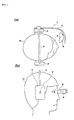
- Fig. 1 is a view showing an outline of a head-mounted display according to a first embodiment of the present invention.
- Fig. 1 (a) is a plan view of the head-mounted display, and
- Fig. 1(b) is a side view of the head-mounted display.
- headphones 2 and 3 are connected by a connection unit 4, and the connection unit 4 has elasticity.
- the head-mounted display 1 is worn on a head H such that the head-mounted display 1 is held by the elasticity of the connection unit 4 while ears are sandwiched between the headphones 2 and 3.
- a support arm 5 is attached to the headphone 3, and the support arm 5 is turnable about a turning axis which is of the lateral direction in wearing the head-mounted display 1.
- a display unit 6 is attached to a leading end portion of the support arm 5 so as to display a video to an eye E of a user.
- a display element 7 is provided in the headphone 2 so as to display an operation of the head-mounted display 1.
- the display element 7 such as LED is lit when the head-mounted display 1 can be used for left eye, and the display element 7 is turned off when the head-mounted display 1 can be used for right eye.
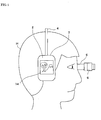
- Fig. 2 is a view showing an outline of a head-mounted display according to a second embodiment of the present invention.
- Fig. 2 (a) is a plan view of the head-mounted display
- Fig. 2(b) is a side view of the head-mounted display.
- the same component as that of Fig. 1 is designated by the same numeral, and the description will be omitted.
- the support arm 5 is turnable about a turning axis which is of a vertical direction of the paper plane to the headphone 3.
- a position of the display unit 6 can be switched between a state in which the display unit 6 is located in front of the eye E and a state in which the display unit 6 is retracted from the front of the eye E.
- a support-arm position detecting sensor 8 detects the states, and the electric power supply to the display element 7 is stopped to turn off the display element 7 when the position of the display unit 6 is located in front of the eye E in wearing the head-mounted display 1.
- the user wears the head-mounted display 1 to observe the video, when the position of the display unit 6 is located in front of the eye E in wearing the head-mounted display 1. In such cases, because the user cannot visibly recognize the display element 7, any troubles are not generated even if the display element 7 is turned off. Therefore, the battery life is lengthened because the need of the electric power supply to the display element 7 is eliminated.
- a human-body proximity switch 9 is provided, and the human-body proximity switch 9 is operated to detect that the user wears the head-mounted display 1 when the user wears the head-mounted display 1 on the head H.
- the human-body proximity switch 9 detects that the user wears the head-mounted display 1 on the head, the electric power supply to the display element 7 is stopped to turn off the display element 7.
- the battery life is lengthened because the need of the electric power supply to the display element 7 is eliminated.
- Fig. 3 is a side view showing an outline of a head-mounted display according to a third embodiment of the present invention.
- the head-mounted display of the third embodiment is substantially similar to the head-mounted display of the second embodiment except that a power status display 11, an HMD (Head-Mounted Display) content display screen 12, and a reproduced audio level display 13 are provided in the headphone 2.
- the power status display 11 is a light-emitting element such as LED which is lit when a main power supply of the head-mounted display is turned on.
- the HMD content display screen 12 is a display element such as a liquid crystal display.
- the HMD content display screen 12 displays contents (such as a title of reproduced music and a title of reproduced movie) reproduced by the display unit 6 or headphones 2 and 3 of the head-mounted display, and the HMD content display screen 12 displays a reproduction/stop state, a reproduction time, and the like.
- the reproduced audio level display 12 is a light-emitting element such as an LED indicator which indicates an audio signal level (magnitude) of contents (such as music) reproduced by the headphones 2 and 3.
- Fig. 4 is a side view showing an outline of a head-mounted display according to a fourth embodiment of the present invention.
- the head-mounted display of the fourth embodiment is substantially similar to the head-mounted display of the second embodiment except that an element for displaying a HMD display equivalent screen 14 is provided in the headphone 2.
- the HMD display equivalent screen 14 is a display element such as a liquid crystal display which displays the same video as that displayed on the display unit 6.
- electric power supplied to an unnecessary display element for display is waste from the viewpoint of energy saving, and viewing information is exposed to the outside in wearing the head-mounted display when a display area is enlarged in order to perform easy viewable display during non-wearing state of the head-mounted display.
- display contents should be in individual privacy, desirably the display contents should not be disclosed to the outside. Therefore, when the user wears the head-mounted display to use the head-mounted display, preferably the power status display 11, the HMD content display screen 12, the reproduced audio level display 13, and the HMD display equivalent screen 14 is turned off or not displayed.
- the head-mounted display 1 including the display unit 6 is described in the above-described embodiments.
- the items described in the embodiments may be applied to an output device such as an audio-dedicated headphone which supplies only sound without the display unit 6.
Landscapes
- Physics & Mathematics (AREA)
- Engineering & Computer Science (AREA)
- General Physics & Mathematics (AREA)
- Theoretical Computer Science (AREA)
- Optics & Photonics (AREA)
- General Health & Medical Sciences (AREA)
- Human Computer Interaction (AREA)
- Audiology, Speech & Language Pathology (AREA)
- General Engineering & Computer Science (AREA)
- Health & Medical Sciences (AREA)
- Multimedia (AREA)
- Acoustics & Sound (AREA)
- Signal Processing (AREA)
- Control Of Indicators Other Than Cathode Ray Tubes (AREA)
Abstract
Description
- The present invention relates to an output device and a video output device.
- Recently there have been various glasses-type video display devices in which video displayed on a display device such as a Liquid Crystal Display (LCD) is observed as a virtual image enlarged through an optical system having an eyepiece, a half mirror, or the like. The glasses-type video display devices are called a head-mounted display. For example,
WO2004/061519A1 (Patent Document 1) discloses an example of the head-mounted display. - Many video display devices are configured in such a way that they are worn on a face while wrapped around a head. Video display devices are mainly classified into a binocular type and a monocular type. In the binocular type, the video display system is formed at positions corresponding to eyes. In the monocular type, the video display system is formed at a position corresponding to one of the right and left eyes. Usually the head-mounted display includes a display unit which displays video and a headphone which supplies a sound.
- A manipulation component (such as a switch) for manipulating the head-mounted display and an operation display component may be provided in a control box or the like provided independently of a head-mounted display main body portion worn on a head. Recently, there is made an attempt to attach the manipulation component or the operation display component to a headphone portion of the head-mounted display main body portion worn on the head.
- Patent Document 1:
WO2004/061519A1 - In the head-mounted display, because the head-mounted display is worn on the head, there is a restriction to dimensions and a weight of the head-mounted display, and a large-capacity battery cannot be mounted on the head-mounted display. Therefore, there is a problem in that there is a limitation to a time the head-mounted display can be used without replacing or charging a battery.
- In view of the foregoing, an object of the present invention is to provide an output device and a video display device which can be used for a long time without replacing or charging the battery.
- In accordance with a first aspect of the present invention, an output device which provides at least one of video and sound to a user while the user wears the output device on a user's head, is provided. The output device has a function of turning off a light-emitting element or a display element located at a position where the user cannot visually recognize the light-emitting element or the display element in wearing the output device.
- In accordance with a second aspect of the present invention, a video display device which displays video in front of an eye of a user while the user wears the video display device on a user's head, is provided. The video display device has a function of turning off a display element located at a position where the user cannot visually recognize the display element in wearing the video display device.
- In accordance with a third aspect of the present invention, an output device which provides at least one of video and sound to a user while the user wears the output device on a user's head, is provided. The output device has a function of turning off a light-emitting element or a display element located at a position where the user cannot visually recognize the light-emitting element or the display element in wearing the output device, when the video or sound is provided.
- In accordance with a fourth aspect of the present invention, a video display device which displays video in front of an eye of a user while the user wears the video display device on a user's head, is provided. The video display device has a function of turning off a display element located at a position where the user cannot visually recognize the display element in wearing the video display device, when the video is displayed.
- In accordance with a fifth aspect of the present invention, a video display device which displays video in front of an eye of a user while the user wears the video display device on a user's head, is provided. The video display device has a function of turning off a display element located at a position where the user cannot visually recognize the display element in wearing the video display device, when a display unit which displays the video is located at a position corresponding to the front of the eye of the user in wearing the video display device.
- Accordingly, the aspects of the present invention can provide the output device and video display device which can be used for a long time without replacing or charging a battery.
-
-
Fig. 1 is a view showing an outline of a head-mounted display according to a first embodiment of the present invention. -
Fig. 2 is a view showing an outline of a head-mounted display according to a second embodiment of the present invention. -
Fig. 3 is a view showing an outline of a head-mounted display according to a third embodiment of the present invention. -
Fig. 4 is a view showing an outline of a head-mounted display according to a fourth embodiment of the present invention. -
- 1
- head-mounted display
- 2
- headphone
- 3
- headphone
- 4
- connection unit
- 5
- support arm
- 6
- display unit
- 7
- display element
- 8
- support-arm position detecting sensor
- 9
- human-body proximity switch
- 11
- power status display
- 12
- HMD content display screen
- 13
- reproduced audio level display
- 14
- HMD display equivalent screen
- Embodiments of the present invention will be described below with reference to the drawings.
Fig. 1 is a view showing an outline of a head-mounted display according to a first embodiment of the present invention.Fig. 1 (a) is a plan view of the head-mounted display, andFig. 1(b) is a side view of the head-mounted display. - In the head-mounted display 1,
headphones connection unit 4, and theconnection unit 4 has elasticity. In wearing the head-mounted display 1, the head-mounted display 1 is worn on a head H such that the head-mounted display 1 is held by the elasticity of theconnection unit 4 while ears are sandwiched between theheadphones support arm 5 is attached to theheadphone 3, and thesupport arm 5 is turnable about a turning axis which is of the lateral direction in wearing the head-mounted display 1. Adisplay unit 6 is attached to a leading end portion of thesupport arm 5 so as to display a video to an eye E of a user. - A
display element 7 is provided in theheadphone 2 so as to display an operation of the head-mounted display 1. For example, thedisplay element 7 such as LED is lit when the head-mounted display 1 can be used for left eye, and thedisplay element 7 is turned off when the head-mounted display 1 can be used for right eye. - In the embodiment, while the video is displayed on the
display unit 6, electric power supply to thedisplay element 7 is stopped to turn off thedisplay element 7. While the video is displayed on thedisplay unit 6, mostly the user wears the head-mounted display 1 to observe the video. In such cases, because the user cannot visibly recognize thedisplay element 7, any troubles are not generated even if thedisplay element 7 is turned off. Therefore, a battery life is lengthened because a need of the electric power supply to thedisplay element 7 is eliminated. -
Fig. 2 is a view showing an outline of a head-mounted display according to a second embodiment of the present invention.Fig. 2 (a) is a plan view of the head-mounted display, andFig. 2(b) is a side view of the head-mounted display. In the following drawings, the same component as that ofFig. 1 is designated by the same numeral, and the description will be omitted. - In
Fig. 2 , thesupport arm 5 is turnable about a turning axis which is of a vertical direction of the paper plane to theheadphone 3. In wearing the head-mounted display 1, a position of thedisplay unit 6 can be switched between a state in which thedisplay unit 6 is located in front of the eye E and a state in which thedisplay unit 6 is retracted from the front of the eye E. A support-armposition detecting sensor 8 detects the states, and the electric power supply to thedisplay element 7 is stopped to turn off thedisplay element 7 when the position of thedisplay unit 6 is located in front of the eye E in wearing the head-mounted display 1. Mostly the user wears the head-mounted display 1 to observe the video, when the position of thedisplay unit 6 is located in front of the eye E in wearing the head-mounted display 1. In such cases, because the user cannot visibly recognize thedisplay element 7, any troubles are not generated even if thedisplay element 7 is turned off. Therefore, the battery life is lengthened because the need of the electric power supply to thedisplay element 7 is eliminated. - In
Fig. 2 , a human-body proximity switch 9 is provided, and the human-body proximity switch 9 is operated to detect that the user wears the head-mounted display 1 when the user wears the head-mounted display 1 on the head H. When the human-body proximity switch 9 detects that the user wears the head-mounted display 1 on the head, the electric power supply to thedisplay element 7 is stopped to turn off thedisplay element 7. When the user wears the head-mounted display 1, because the user cannot visibly recognize thedisplay element 7, any troubles are not generated even if thedisplay element 7 is turned off. Therefore, the battery life is lengthened because the need of the electric power supply to thedisplay element 7 is eliminated. -
Fig. 3 is a side view showing an outline of a head-mounted display according to a third embodiment of the present invention. The head-mounted display of the third embodiment is substantially similar to the head-mounted display of the second embodiment except that apower status display 11, an HMD (Head-Mounted Display)content display screen 12, and a reproducedaudio level display 13 are provided in theheadphone 2. Thepower status display 11 is a light-emitting element such as LED which is lit when a main power supply of the head-mounted display is turned on. The HMDcontent display screen 12 is a display element such as a liquid crystal display. The HMDcontent display screen 12 displays contents (such as a title of reproduced music and a title of reproduced movie) reproduced by thedisplay unit 6 orheadphones content display screen 12 displays a reproduction/stop state, a reproduction time, and the like. The reproducedaudio level display 12 is a light-emitting element such as an LED indicator which indicates an audio signal level (magnitude) of contents (such as music) reproduced by theheadphones -
Fig. 4 is a side view showing an outline of a head-mounted display according to a fourth embodiment of the present invention. The head-mounted display of the fourth embodiment is substantially similar to the head-mounted display of the second embodiment except that an element for displaying a HMD displayequivalent screen 14 is provided in theheadphone 2. The HMD displayequivalent screen 14 is a display element such as a liquid crystal display which displays the same video as that displayed on thedisplay unit 6. - In the third and fourth embodiments, electric power supplied to an unnecessary display element for display is waste from the viewpoint of energy saving, and viewing information is exposed to the outside in wearing the head-mounted display when a display area is enlarged in order to perform easy viewable display during non-wearing state of the head-mounted display. Because display contents should be in individual privacy, desirably the display contents should not be disclosed to the outside. Therefore, when the user wears the head-mounted display to use the head-mounted display, preferably the
power status display 11, the HMDcontent display screen 12, the reproducedaudio level display 13, and the HMD displayequivalent screen 14 is turned off or not displayed. - The head-mounted display 1 including the
display unit 6 is described in the above-described embodiments. Alternatively, the items described in the embodiments may be applied to an output device such as an audio-dedicated headphone which supplies only sound without thedisplay unit 6.
Claims (5)
- An output device which provides at least one of video and sound to a user while the user wears the output device on a user's head, characterized in that the output device has a function of turning off a light-emitting element or a display element located at a position where the user cannot visually recognize the light-emitting element or the display element in wearing the output device.
- A video display device which displays video in front of an eye of a user while the user wears the video display device on a user's head, characterized in that the video display device has a function of turning off a display element located at a position where the user cannot visually recognize the display element in wearing the video display device.
- An output device which provides at least one of video and sound to a user while the user wears the output device on a user's head, characterized in that the output device has a function of turning off a light-emitting element or a display element located at a position where the user cannot visually recognize the light-emitting element or the display element in wearing the output device, when the video or sound is provided.
- A video display device which displays video in front of an eye of a user while the user wears the video display device on a user's head, characterized in that the video display device has a function of turning off a display element located at a position where the user cannot visually recognize the display element in wearing the video display device, when the video is displayed.
- A video display device which displays video in front of an eye of a user while the user wears the video display device on a user's head, characterized in that the video display device has a function of turning off a display element located at a position where the user cannot visually recognize the display element in wearing the video display device, when a display unit which displays the video is located at a position corresponding to the front of the eye of the user in wearing the video display device.
Applications Claiming Priority (2)
| Application Number | Priority Date | Filing Date | Title |
|---|---|---|---|
| JP2006201492 | 2006-07-25 | ||
| PCT/JP2007/064343 WO2008013110A1 (en) | 2006-07-25 | 2007-07-20 | Outputting apparatus and image display apparatus |
Publications (2)
| Publication Number | Publication Date |
|---|---|
| EP2046026A1 true EP2046026A1 (en) | 2009-04-08 |
| EP2046026A4 EP2046026A4 (en) | 2010-05-05 |
Family
ID=38981422
Family Applications (1)
| Application Number | Title | Priority Date | Filing Date |
|---|---|---|---|
| EP07791080A Ceased EP2046026A4 (en) | 2006-07-25 | 2007-07-20 | Outputting apparatus and image display apparatus |
Country Status (5)
| Country | Link |
|---|---|
| US (2) | US20090243966A1 (en) |
| EP (1) | EP2046026A4 (en) |
| JP (1) | JP5195426B2 (en) |
| CN (1) | CN101496400B (en) |
| WO (1) | WO2008013110A1 (en) |
Cited By (3)
| Publication number | Priority date | Publication date | Assignee | Title |
|---|---|---|---|---|
| EP2685733A4 (en) * | 2011-03-06 | 2014-09-10 | Sony Corp | DISPLAY SYSTEM, DISPLAY DEVICE, AND RELAY DEVICE |
| EP2424260A3 (en) * | 2010-08-30 | 2015-02-18 | Canon Kabushiki Kaisha | Image processing apparatus and image processing method |
| EP3019929A4 (en) * | 2013-07-10 | 2017-03-01 | LG Electronics Inc. | Head mounted display device including multiple user interface formats and method of controlling therefor |
Families Citing this family (23)
| Publication number | Priority date | Publication date | Assignee | Title |
|---|---|---|---|---|
| JP5428174B2 (en) * | 2008-03-24 | 2014-02-26 | 株式会社ニコン | Head mounted display device |
| US9606612B2 (en) | 2010-07-20 | 2017-03-28 | Empire Technology Development Llc | Augmented reality proximity sensing |
| JP5810540B2 (en) * | 2011-02-04 | 2015-11-11 | セイコーエプソン株式会社 | Head-mounted display device and method for controlling head-mounted display device |
| CN102345670A (en) * | 2011-06-24 | 2012-02-08 | 无锡杰思物流设备有限公司 | Rubber wrapping cutting roller |
| JP5936379B2 (en) * | 2012-02-07 | 2016-06-22 | シャープ株式会社 | Image display device |
| CN103364950B (en) * | 2012-03-31 | 2016-12-14 | 联想(北京)有限公司 | Display device and display packing |
| US8736692B1 (en) * | 2012-07-09 | 2014-05-27 | Google Inc. | Using involuntary orbital movements to stabilize a video |
| US9851787B2 (en) * | 2012-11-29 | 2017-12-26 | Microsoft Technology Licensing, Llc | Display resource management |
| WO2014129212A1 (en) * | 2013-02-22 | 2014-08-28 | ソニー株式会社 | Image display device, image display method, storage medium, and monitoring system |
| FR3006455A1 (en) * | 2013-05-31 | 2014-12-05 | Optinvent | OCULAR VISION SYSTEM WITH OPTICAL GUIDE POSITIONABLE IN TWO POSITIONS |
| CN104254025A (en) * | 2013-06-27 | 2014-12-31 | 麦祖怀 | Intelligent headset |
| US9183612B2 (en) | 2013-09-04 | 2015-11-10 | Qualcomm Incorporated | Wearable display device use-based data processing control |
| CN104516407B (en) * | 2013-09-27 | 2019-01-01 | 联想(北京)有限公司 | A kind of wearable electronic equipment and information processing method |
| US10761566B2 (en) | 2013-09-27 | 2020-09-01 | Beijing Lenovo Software Ltd. | Electronic apparatus and method for processing information |
| US8958158B1 (en) | 2013-12-03 | 2015-02-17 | Google Inc. | On-head detection for head-mounted display |
| JP6589855B2 (en) * | 2014-02-21 | 2019-10-16 | ソニー株式会社 | Head-mounted display, control device, and control method |
| CN103823305B (en) * | 2014-03-06 | 2016-09-14 | 成都贝思达光电科技有限公司 | A kind of nearly eye display optical system based on curved microlens array |
| US9933995B2 (en) * | 2015-01-25 | 2018-04-03 | Harman International Industries, Incorporated | Headphones with integral image display |
| US10545714B2 (en) * | 2015-09-04 | 2020-01-28 | Samsung Electronics Co., Ltd. | Dual screen head mounted display |
| KR102400900B1 (en) * | 2015-10-26 | 2022-05-23 | 엘지전자 주식회사 | System |
| WO2017140255A1 (en) * | 2016-02-17 | 2017-08-24 | 王浩 | Display device with adjustable angle of view |
| US10997943B2 (en) * | 2018-03-02 | 2021-05-04 | Facebook Technologies, Llc | Portable compute case for storing and wirelessly communicating with an eyewear device |
| WO2024209228A1 (en) * | 2023-04-03 | 2024-10-10 | Luxottica S.R.L. | Case for electronic devices and related electronic device |
Family Cites Families (40)
| Publication number | Priority date | Publication date | Assignee | Title |
|---|---|---|---|---|
| DE68909934T2 (en) * | 1989-08-11 | 1994-04-07 | Andre Tisseront | Hard hat. |
| US5815126A (en) * | 1993-10-22 | 1998-09-29 | Kopin Corporation | Monocular portable communication and display system |
| JP3679506B2 (en) * | 1996-06-03 | 2005-08-03 | キヤノン株式会社 | Display device |
| JP3530679B2 (en) * | 1996-06-14 | 2004-05-24 | キヤノン株式会社 | Imaging device with eyepiece detection function |
| US6289332B2 (en) * | 1999-02-26 | 2001-09-11 | Freightliner Corporation | Integrated message display system for a vehicle |
| US20020013852A1 (en) * | 2000-03-03 | 2002-01-31 | Craig Janik | System for providing content, management, and interactivity for thin client devices |
| JP2001128035A (en) * | 1999-10-26 | 2001-05-11 | Minolta Co Ltd | Digital camera |
| US7150526B2 (en) * | 2000-06-02 | 2006-12-19 | Oakley, Inc. | Wireless interactive headset |
| US6769767B2 (en) * | 2001-04-30 | 2004-08-03 | Qr Spex, Inc. | Eyewear with exchangeable temples housing a transceiver forming ad hoc networks with other devices |
| US7046230B2 (en) * | 2001-10-22 | 2006-05-16 | Apple Computer, Inc. | Touch pad handheld device |
| FI113130B (en) * | 2002-04-17 | 2004-02-27 | Nokia Corp | Portable, foldable electronic device equipped with telephone and camera functions |
| WO2004005868A2 (en) * | 2002-07-10 | 2004-01-15 | Lockheed Martin Corporation | Infrared camera system and method |
| JP2005534269A (en) * | 2002-07-26 | 2005-11-10 | オークレイ・インコーポレイテッド | Wireless interactive headset |
| JP3988632B2 (en) * | 2002-11-28 | 2007-10-10 | 日本電気株式会社 | Control method of glasses-type display |
| WO2004061519A1 (en) | 2002-12-24 | 2004-07-22 | Nikon Corporation | Head mount display |
| JP4069752B2 (en) * | 2003-01-31 | 2008-04-02 | 株式会社ニコン | Display device |
| US7806525B2 (en) * | 2003-10-09 | 2010-10-05 | Ipventure, Inc. | Eyeglasses having a camera |
| US7380936B2 (en) * | 2003-10-09 | 2008-06-03 | Ipventure, Inc. | Eyeglasses with a clock or other electrical component |
| US7255437B2 (en) * | 2003-10-09 | 2007-08-14 | Howell Thomas A | Eyeglasses with activity monitoring |
| US6982633B2 (en) * | 2003-05-12 | 2006-01-03 | Joshua Burdick | Helmet having a ring of light |
| DE602004023831D1 (en) * | 2003-05-12 | 2009-12-10 | Elbit Systems Ltd | METHOD AND SYSTEM FOR AUDIOVISUAL COMMUNICATION |
| WO2004107808A2 (en) * | 2003-05-28 | 2004-12-09 | Koninklijke Philips Electronics N.V. | Display screen loudspeaker |
| US7113811B2 (en) * | 2003-06-17 | 2006-09-26 | Agere Systems Inc. | System and method for conserving battery power in a mobile station |
| US20050017911A1 (en) * | 2003-07-21 | 2005-01-27 | Jen-Feng Lee | Helmet with built-in antenna |
| KR100608731B1 (en) * | 2003-12-22 | 2006-08-04 | 엘지전자 주식회사 | Swivel handset and call method using same |
| JP4373286B2 (en) * | 2004-05-06 | 2009-11-25 | オリンパス株式会社 | Head-mounted display device |
| JP2006005804A (en) * | 2004-06-18 | 2006-01-05 | Konica Minolta Photo Imaging Inc | System, method, and apparatus |
| US7653883B2 (en) * | 2004-07-30 | 2010-01-26 | Apple Inc. | Proximity detector in handheld device |
| US7327239B2 (en) * | 2004-08-06 | 2008-02-05 | Invision Systems, Llc | Heads-up speed display for vehicles |
| KR100677382B1 (en) * | 2004-11-09 | 2007-02-02 | 엘지전자 주식회사 | How to switch screen in mobile terminal |
| US7461162B2 (en) * | 2004-12-16 | 2008-12-02 | International Business Machines Corporation | Usage consciousness in HTTP/HTML for reducing unused data flow across a network |
| EP1833170A4 (en) * | 2004-12-24 | 2013-05-01 | Sharp Kk | Broadcast receiver |
| US20060166702A1 (en) * | 2005-01-24 | 2006-07-27 | Dietz Paul H | Cellular telephone with ear proximity display and lighting control |
| US8033830B2 (en) * | 2005-05-30 | 2011-10-11 | Honda Motor Co., Ltd. | Vehicle simulation system |
| US20060281499A1 (en) * | 2005-06-09 | 2006-12-14 | Farrow Daniel W | System and method for using a label to reduce the power consumption of a light source |
| US20070004451A1 (en) * | 2005-06-30 | 2007-01-04 | C Anderson Eric | Controlling functions of a handheld multifunction device |
| US8564544B2 (en) * | 2006-09-06 | 2013-10-22 | Apple Inc. | Touch screen device, method, and graphical user interface for customizing display of content category icons |
| US20080220820A1 (en) * | 2007-03-09 | 2008-09-11 | Sony Ericsson Mobile Communications Ab | Battery saving selective screen control |
| US8294659B2 (en) * | 2007-05-18 | 2012-10-23 | Apple Inc. | Secondary backlight indicator for portable media devices |
| US8068925B2 (en) * | 2007-06-28 | 2011-11-29 | Apple Inc. | Dynamic routing of audio among multiple audio devices |
-
2007
- 2007-07-20 JP JP2008526742A patent/JP5195426B2/en not_active Expired - Fee Related
- 2007-07-20 WO PCT/JP2007/064343 patent/WO2008013110A1/en not_active Ceased
- 2007-07-20 US US12/309,393 patent/US20090243966A1/en not_active Abandoned
- 2007-07-20 CN CN2007800280424A patent/CN101496400B/en not_active Expired - Fee Related
- 2007-07-20 EP EP07791080A patent/EP2046026A4/en not_active Ceased
-
2015
- 2015-12-22 US US14/978,366 patent/US20160110157A1/en not_active Abandoned
Cited By (5)
| Publication number | Priority date | Publication date | Assignee | Title |
|---|---|---|---|---|
| EP2424260A3 (en) * | 2010-08-30 | 2015-02-18 | Canon Kabushiki Kaisha | Image processing apparatus and image processing method |
| EP2685733A4 (en) * | 2011-03-06 | 2014-09-10 | Sony Corp | DISPLAY SYSTEM, DISPLAY DEVICE, AND RELAY DEVICE |
| RU2602363C2 (en) * | 2011-03-06 | 2016-11-20 | Сони Корпорейшн | Display system, display device and relay device |
| US10230938B2 (en) | 2011-03-06 | 2019-03-12 | Sony Corporation | Display system, display device, and relay device |
| EP3019929A4 (en) * | 2013-07-10 | 2017-03-01 | LG Electronics Inc. | Head mounted display device including multiple user interface formats and method of controlling therefor |
Also Published As
| Publication number | Publication date |
|---|---|
| US20090243966A1 (en) | 2009-10-01 |
| CN101496400B (en) | 2011-11-16 |
| US20160110157A1 (en) | 2016-04-21 |
| WO2008013110A1 (en) | 2008-01-31 |
| CN101496400A (en) | 2009-07-29 |
| JP5195426B2 (en) | 2013-05-08 |
| EP2046026A4 (en) | 2010-05-05 |
| JPWO2008013110A1 (en) | 2009-12-17 |
Similar Documents
| Publication | Publication Date | Title |
|---|---|---|
| US20090243966A1 (en) | Outputting apparatus and image display apparatus | |
| JP5120253B2 (en) | Head mounted display | |
| US8451229B2 (en) | Monocular video display device | |
| JP2009171505A (en) | Head mounted display | |
| JP2021121049A (en) | Power saving control program for head-mounted display devices and head-mounted display devices | |
| JP5071387B2 (en) | Display device | |
| JP2004233908A (en) | Head mounted display | |
| JP2013238813A (en) | Head-mounted display device | |
| JP5055585B2 (en) | Head mounted display | |
| JP2005072867A (en) | Head-attached display device | |
| JP2007052224A (en) | Image display apparatus | |
| JPWO2007145122A1 (en) | Video display device | |
| JP2006158479A (en) | Video display device | |
| JP4904976B2 (en) | Headphone and head mounted display | |
| JP2008048231A (en) | Head mounted display | |
| JP2008028552A (en) | Display device | |
| JP2007219116A (en) | Head mounted display | |
| JP2008147745A (en) | Audio output device | |
| JP2008147744A (en) | Output device | |
| JP4066453B2 (en) | Head mounted display | |
| JP2008048232A (en) | Head mounted display | |
| JP2008026681A (en) | Video display device | |
| JP2012070019A (en) | Output device | |
| JP2008048316A (en) | Head mounted display | |
| JP2004233783A (en) | Head mounted display |
Legal Events
| Date | Code | Title | Description |
|---|---|---|---|
| PUAI | Public reference made under article 153(3) epc to a published international application that has entered the european phase |
Free format text: ORIGINAL CODE: 0009012 |
|
| 17P | Request for examination filed |
Effective date: 20081230 |
|
| AK | Designated contracting states |
Kind code of ref document: A1 Designated state(s): AT BE BG CH CY CZ DE DK EE ES FI FR GB GR HU IE IS IT LI LT LU LV MC MT NL PL PT RO SE SI SK TR |
|
| AX | Request for extension of the european patent |
Extension state: AL BA HR MK RS |
|
| A4 | Supplementary search report drawn up and despatched |
Effective date: 20100401 |
|
| RAP1 | Party data changed (applicant data changed or rights of an application transferred) |
Owner name: NIKON CORPORATION |
|
| 17Q | First examination report despatched |
Effective date: 20100629 |
|
| DAX | Request for extension of the european patent (deleted) | ||
| REG | Reference to a national code |
Ref country code: DE Ref legal event code: R003 |
|
| STAA | Information on the status of an ep patent application or granted ep patent |
Free format text: STATUS: THE APPLICATION HAS BEEN REFUSED |
|
| 18R | Application refused |
Effective date: 20130314 |