EP2045924A1 - Semiconductor circuit - Google Patents
Semiconductor circuit Download PDFInfo
- Publication number
- EP2045924A1 EP2045924A1 EP08017216A EP08017216A EP2045924A1 EP 2045924 A1 EP2045924 A1 EP 2045924A1 EP 08017216 A EP08017216 A EP 08017216A EP 08017216 A EP08017216 A EP 08017216A EP 2045924 A1 EP2045924 A1 EP 2045924A1
- Authority
- EP
- European Patent Office
- Prior art keywords
- differential
- section
- semiconductor circuit
- transistor
- signal output
- Prior art date
- Legal status (The legal status is an assumption and is not a legal conclusion. Google has not performed a legal analysis and makes no representation as to the accuracy of the status listed.)
- Withdrawn
Links
Images


Classifications
-
- H—ELECTRICITY
- H03—ELECTRONIC CIRCUITRY
- H03K—PULSE TECHNIQUE
- H03K3/00—Circuits for generating electric pulses; Monostable, bistable or multistable circuits
- H03K3/02—Generators characterised by the type of circuit or by the means used for producing pulses
- H03K3/353—Generators characterised by the type of circuit or by the means used for producing pulses by the use, as active elements, of field-effect transistors with internal or external positive feedback
- H03K3/356—Bistable circuits
- H03K3/356104—Bistable circuits using complementary field-effect transistors
- H03K3/356113—Bistable circuits using complementary field-effect transistors using additional transistors in the input circuit
- H03K3/35613—Bistable circuits using complementary field-effect transistors using additional transistors in the input circuit the input circuit having a differential configuration
-
- G—PHYSICS
- G11—INFORMATION STORAGE
- G11C—STATIC STORES
- G11C7/00—Arrangements for writing information into, or reading information out from, a digital store
- G11C7/22—Read-write [R-W] timing or clocking circuits; Read-write [R-W] control signal generators or management
-
- H—ELECTRICITY
- H03—ELECTRONIC CIRCUITRY
- H03F—AMPLIFIERS
- H03F3/00—Amplifiers with only discharge tubes or only semiconductor devices as amplifying elements
- H03F3/45—Differential amplifiers
-
- H—ELECTRICITY
- H03—ELECTRONIC CIRCUITRY
- H03K—PULSE TECHNIQUE
- H03K19/00—Logic circuits, i.e. having at least two inputs acting on one output; Inverting circuits
- H03K19/0175—Coupling arrangements; Interface arrangements
-
- H—ELECTRICITY
- H03—ELECTRONIC CIRCUITRY
- H03K—PULSE TECHNIQUE
- H03K3/00—Circuits for generating electric pulses; Monostable, bistable or multistable circuits
- H03K3/02—Generators characterised by the type of circuit or by the means used for producing pulses
- H03K3/26—Generators characterised by the type of circuit or by the means used for producing pulses by the use, as active elements, of bipolar transistors with internal or external positive feedback
- H03K3/28—Generators characterised by the type of circuit or by the means used for producing pulses by the use, as active elements, of bipolar transistors with internal or external positive feedback using means other than a transformer for feedback
- H03K3/281—Generators characterised by the type of circuit or by the means used for producing pulses by the use, as active elements, of bipolar transistors with internal or external positive feedback using means other than a transformer for feedback using at least two transistors so coupled that the input of one is derived from the output of another, e.g. multivibrator
- H03K3/286—Generators characterised by the type of circuit or by the means used for producing pulses by the use, as active elements, of bipolar transistors with internal or external positive feedback using means other than a transformer for feedback using at least two transistors so coupled that the input of one is derived from the output of another, e.g. multivibrator bistable
- H03K3/288—Generators characterised by the type of circuit or by the means used for producing pulses by the use, as active elements, of bipolar transistors with internal or external positive feedback using means other than a transformer for feedback using at least two transistors so coupled that the input of one is derived from the output of another, e.g. multivibrator bistable using additional transistors in the input circuit
- H03K3/2885—Generators characterised by the type of circuit or by the means used for producing pulses by the use, as active elements, of bipolar transistors with internal or external positive feedback using means other than a transformer for feedback using at least two transistors so coupled that the input of one is derived from the output of another, e.g. multivibrator bistable using additional transistors in the input circuit the input circuit having a differential configuration
Definitions
- the present invention relates to a semiconductor circuit and, more particularly, to a semiconductor circuit to correct degradation in duty cycle of a differential signal to be output.
- CML current mode logic
- CMOS level signal level having a large amplitude
- Fig. 18 shows a schematic diagram of a circuit 1800 receiving differential clock signals that are small signals such as the CML level, to convert the differential clock signals into differential clock signals having a large amplitude such as the CMOS level to be distributed.
- multiple stages of differential amplifiers 1801 and 1802 first amplify differential clock signals IT and IB that are small signals of the CML level, and then output differential clock signals OT and OB that are converted into signals of the CMOS level.
- the differential clock signals IT and IB are abbreviated as IT/IB and the differential clock signals OT and OB are also abbreviated as OT/OB. The same is applied to other differential signals.
- the differential amplifiers 1801 and 1802 shown in Fig. 18 there is used a circuit disclosed in Japanese Patent No. 7-16158 .
- Examples of the circuit include a differential amplifier 1900 as shown in Fig. 19 .
- the differential amplifier 1900 includes NMOS transistors N1901a and N1901b, NMOS transistors N1902a and N1902b, and PMOS transistors P1903a and P1903b.
- the differential amplifier 1900 as shown in Fig. 19 when the differential signals IT/IB to be input have different offsets, there arises a problem in that offset components are also amplified, with the result that the degradation in duty cycle is increased.
- a differential amplifier 2000 disclosed in Japanese Unexamined Patent Application Publication No. 2007-60069 .
- the differential amplifier 2000 is constituted by adding PMOS transistors P2001a and P2001b, NMOS transistors N2002a and N2002b, and a transfer gate 2003 to the differential amplifier 1900.
- the solid line of Fig. 21 represents a frequency characteristic of the differential amplifier 2000
- the dashed line of Fig. 21 represents a frequency characteristic of the differential amplifier 1900.
- the differential amplifier 2000 suppresses the amplitude of a low-frequency component and amplifies the amplitude of a predetermined high-frequency component. Consideration is given to a case where the input differential signals IT/IB are input to the differential amplifier 2000 as shown in Fig. 22 .
- the input differential signals IT/IB shown in Fig. 22 have an amplitude Y1 and a difference in offset voltage of X1.
- the duty cycle of the differential signals is, for example, 60:40, whereby symmetry is lowered.
- the differential amplifier 2000 suppresses the amplitude of the low-frequency component and amplifies the amplitude of the predetermined high-frequency component, thereby suppressing an offset voltage component of each of the input differential signals IT/IB and amplifying the amplitude of a signal component having the amplitude Y1.
- the differential amplifier 2000 outputs output differential signals OT/OB having an amplitude of Y2 and a difference in offset voltage of X2.
- the degradation in duty cycle of the output differential signals OT/OB is improved, and the duty cycle is about 50:50.
- the correction of the degradation in duty cycle by the differential amplifier 2000 is effective only for the input differential signals IT/IB input to input terminals IT and IB of the differential amplifier 2000.
- Japanese Unexamined Patent Application Publication No. 11-274902 discloses a technique in which a low-pass filter is connected to a differential output of a differential receiver and a difference in output of the low-pass filter is amplified to be fed back to an input of the differential receiver, thereby correcting the duty cycle.
- elements such as transistors constituting a correction differential amplifier vary, there arises a problem in that an input offset cannot be compensated and the duty cycle of a differential signal to be output is degraded.
- a semiconductor circuit including: a differential input section to receive input differential signals; a load resistance section to output a voltage according to a current output by the differential input section; differential signal output terminals to output a differential signal corresponding to the voltage output from the load resistance section; a low-pass filter to extract a direct-current component of the differential signal output from the differential signal output terminals; and a load adjustment section to feed back the direct-current component extracted by the low-pass filter to adjust a resistance value of the load resistance section.
- the semiconductor circuit according to the present invention feeds back a DC voltage component of an offset from the differential signal output terminals, which is extracted from the low-pass filter, to the differential input section receiving the input differential signal.
- a feedback loop is constituted so that the DC voltage component fed back as described above is used by the load adjustment section to adjust the resistance value of the load resistance section. Accordingly, the circuit constituting the feedback loop corrects the degradation in duty cycle of the differential signals output from the differential signal output terminals.
- the present invention it is possible to correct not only the degradation in duty cycle of input differential signals, but also the degradation in duty cycle due to variations among transistors constituting the circuit itself, which cannot be corrected by the conventional differential amplifier, with a simple circuit configuration.
- the present invention is applied to a semiconductor circuit 100 to amplify small-amplitude differential clock signals and convert the amplified differential clock signals into large-amplitude differential clock signals.
- Fig. 1 shows an example of a schematic configuration of the semiconductor circuit 100 according to the first embodiment.
- the semiconductor circuit 100 includes differential amplifiers 110 and 120, CMOS inverters 130a and 130b, and a low-pass filter 140.
- the differential amplifier 110 receives input differential signals IT/IB and outputs amplified differential signals PB/PT.
- the differential amplifier 120 receives the differential signals PB/PT and outputs amplified differential signals QT/QB.
- the CMOS inverters 130a and 130b invert the differential signals QT/QB, respectively, and output differential signals OB/OT, respectively.
- the low-pass filter 140 receives the differential signals OB/OT and outputs voltage signals RB/RT, which are direct-current components of the differential signals OB/OT, to the differential amplifier 110.
- Fig. 2 shows a detailed circuit configuration of the semiconductor circuit 100 shown in Fig. 1 .
- the differential amplifier 110 includes a differential input section 111, a load resistance section 112, a load adjustment section 113, and differential signal output terminals 114a and 114b.
- the differential input section 111 includes NMOS transistors N111a and N111b.
- the NMOS transistors N111a and N111b have gates receiving the input differential signals IT/IB, respectively, and drains connected to nodes A1 and A2, respectively.
- the load adjustment section 113 includes NMOS transistors N112a and N112b.
- the NMOS transistors N112a and N112b have gates receiving the voltage signals RB/RT, respectively, which are direct-current components from the low-pass filter 140. Further, the NMOS transistors N112a and N112b have drains connected to sources of the NMOS transistors N111a and N111b, respectively, and sources each connected to a ground terminal.
- the load resistance section 112 includes NMOS transistors N113a and N113b.
- the NMOS transistors N113a and N113b have gates each receiving a predetermined voltage. Further, the NMOS transistors N113a and N113b have drains connected to the differential signal output terminals 114a and 114b, respectively, and sources connected to the nodes A1 and A2, respectively.
- the load resistance section 112 further includes PMOS transistors P114a and P114b.
- the PMOS transistors P114a and P114b have gates receiving potentials at the nodes A2 and A1, respectively. Further, the PMOS transistors P114a and P114b have sources each connected to a power supply voltage terminal, and drains connected to the differential signal output terminals 114a and 114b, respectively.
- the differential signal output terminals 114a and 114b output voltages as the differential signals PB/PT, respectively, to the differential amplifier 120.
- the voltages are generated by the load resistance section 112 with currents flowing through the transistors N111a and N111b of the differential input section 111 in accordance with the input differential signals IT/IB, respectively.
- the differential amplifier 120 includes a differential input section 121, a load resistance section 122, and differential signal output terminals 123a and 123b.
- the differential amplifier 120 functions as a differential buffer to amplify and output the input differential signals.
- the differential input section 121 includes NMOS transistors N121a and N121b.
- the NMOS transistors N121a and N121b have gates receiving the differential signals PB/PT, respectively, which are output from the differential amplifier 110. Further, the NMOS transistors N121a and N121b have sources each connected to the ground terminal, and drains connected to nodes B1 and B2, respectively.
- the load resistance section 122 includes NMOS transistors N122a and N122b.
- the NMOS transistors N122a and N122b have gates each receiving a predetermined voltage. Further, the NMOS transistors N122a and N122b have drains connected to the differential signal output terminals 123a and 123b, respectively, and sources connected to the nodes B1 and B2, respectively.
- the load resistance section 122 further includes PMOS transistors P123a and P123b.
- the PMOS transistors P123a and P123b have gates receiving potentials at the nodes B2 and B1, respectively. Further, the PMOS transistors P123a and P123b have sources each connected to the power supply voltage terminal, and drains connected to the differential signal output terminals 123a and 123b, respectively.
- the differential signal output terminals 123a and 123b output voltages as the differential signals QT/QB to the CMOS inverters 130a and 130b, respectively.
- the circuit configuration shown in Fig. 2 is similar to that of the differential amplifier 1900 of the related art, but the circuit may be realized in another circuit configuration.
- the CMOS inverters 130a and 130b buffer and invert the differential signals QT/QB, respectively, and output the signals as the differential signals OB/OT to nodes C1 and C2, respectively.
- the low-pass filter 140 includes transfer gates 141a and 141b and PMOS transistors P142a and P142b.
- the transfer gates 141a and 141b constitute a resistance section.
- the PMOS transistors P142a and P142b constitute a gate capacitance section 142.
- the transfer gate 141a is connected between the node C1 to which an output terminal of the CMOS inverter 130a is connected, and a node D1
- the transfer gate 141b is connected between the node C2 to which an output terminal of the CMOS inverter 130b is connected, and a node D2.
- the PMOS transistor P142a constituting the gate capacitance section 142 has a gate connected to the node D2, and a source and a drain that are connected to the node D1.
- the PMOS transistor P142b constituting the gate capacitance section 142 has a gate connected to the node D1, and a source and a drain that are connected to the node D2.
- the transfer gates 141a and 141b are used as resistor elements of the low-pass filter 140.
- Gate capacitances of the PMOS transistors P142a and P142b are used as capacitor elements of the low-pass filter 140.
- an RC low-pass filer is formed by a resistance value of each of the transfer gates 141a and 141b and a gate capacitance of each of the PMOS transistors P142a and P142b.
- the input differential signals IT/IB shown in Fig. 3 are small-amplitude sine waves obtained by adding an offset between differential signals, that is, superimposing a predetermined offset voltage on the signal IB, which degrades the duty cycle of the signals.
- the input differential signals IT/IB input to the differential amplifier 110 serving as a first-stage differential amplifier of the semiconductor circuit 100 are amplified by the differential amplifier 110 and output as the differential signals PB/PT, respectively.
- differential signals PB/PT input to the differential amplifier 120 serving as a second-stage differential amplifier are amplified by the differential amplifier 120 and output as the differential signals QT/QB, respectively.
- differential signals QT/QB are inverted into the differential signals OB/OT of the CMOS level by the third-stage CMOS inverters 130a and 130b, respectively, and the differential signals are output as a final output of the semiconductor circuit 100.
- a DC voltage component is extracted from each of the differential signals OB/OT by the low-pass filter 140, and the signals RB/RT, which are DC voltages, are output.
- the potentials of the signals RB/RT, which are DC voltages fluctuate in accordance with the amount of degradation in duty cycle.
- the duty cycle of the input differential signals IT/IB shown in Fig. 3 is degraded since the offset is added to the signal IB as described above.
- the duty cycle of the differential signals OB/OT is also degraded.
- the potential of the signal RT which is an output from the low-pass filter 140, becomes lower than the potential of the signal RB.
- the signals RB/RT are fed back to the load adjustment section 113 of the differential amplifier 110 serving as the first-stage differential amplifier of the semiconductor circuit 100. Then, the load adjustment section 113 adjusts the offset of the input of the differential input section 111 by using the signals RB/RT.
- the offset of the input of the signal IB is reduced, whereby the degradation in duty cycle due to the offset added to the signal IB is reduced.
- the degradation in duty cycle of the differential signals PB/PT which are output signals of the differential amplifier 110, is corrected.
- the corrected differential signals PB/PT are input to the second-stage differential amplifier 120, and are then output as differential signals QT/QB. Further, the differential signals QT/QB are input to the CMOS inverters 130a and 130b, respectively, and are then output as the differential signals OB/OT. Thus, the degradation in duty cycle of the differential signals OB/OT that are output from the CMOS inverters 130a and 130b, respectively, as the final output of the semiconductor circuit 100 is also corrected.
- the semiconductor circuit 100 feeds back the signals RB/RT corresponding to the differential signals OB/OT of the final output, to the first-stage differential amplifier 110.
- the correction is effective not only for the degradation in duty cycle of the input differential signals IT/IB, but also for the degradation in duty cycle due to the relative variations among transistors constituting the differential amplifiers 110 and 120 and the CMOS inverters 130a and 130b.
- consideration is given to a case where the input differential signals IT/IB, the duty cycle of which is not degraded, are input, while the duty cycle of the differential signals OB/OT is degraded due to the relative variations among transistors constituting the differential amplifiers 110 and 120.
- the signals RB/RT extracted from the differential signals OB/OT by the low-pass filter 140 fluctuate according to the offset generated by the differential amplifiers 110 and 120.
- the signals RB/RT which are fed back to the differential amplifier 110, control the offset of the input of the differential input section 111 to cause the load adjustment section 113 to reduce the offset.
- the semiconductor circuit 100 outputs the differential signals OB/OT as the final output of the circuit.
- the differential signals OB/OT are input to the low-pass filter 140, and then the signals RB/RT as the DC voltage components are extracted.
- the semiconductor circuit 100 causes the signals RB/RT to be fed back to the first-stage differential amplifier of the circuit to adjust the offset of the input, thereby correcting the degradation in duty cycle of the differential signals OB/OT as the final output signals.
- the semiconductor circuit 100 is capable of correcting not only the degradation in duty cycle of the input differential signals IT/IB input to the semiconductor circuit 100, but also the degradation in duty cycle due to the relative variations among transistors constituting the semiconductor circuit 100.
- the semiconductor circuit 100 is capable of enhancing the effect of correcting the degradation in duty cycle of the output signals. Further, since only the low-pass filter 140 and the load adjustment section 113 are added in the first embodiment, an increase in circuit scale is suppressed. Further, the circuit according to the first embodiment has advantages in that the low-pass filter 140 and the load adjustment section 113 have low power consumption, for example.
- the low-pass filter 140 may be configured as shown in Figs. 4 , 5 , and 6 .
- a source and a drain of each of PMOS transistors P143a and P143b, which constitute the gate capacitance section 142 may be connected to the ground terminal.
- a capacitor element C144 may be used instead of the gate capacitance section 142 of the PMOS transistors.
- resistor elements R145a and R145b may be used instead of the transfer gates 141a and 141b.
- the PMOS transistors constituting the gate capacitance section 142 may be replaced with NMOS transistors.
- resistor elements R145a and R145b may be used instead of the transfer gates 141a and 141b, and the capacitor element C144 may be used instead of the gate capacitance section 142.
- resistor elements R145a and R145b may be used instead of the transfer gates 141a and 141b
- capacitor element C144 may be used instead of the gate capacitance section 142.
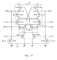
- the first-stage differential amplifier 110 may be configured as shown in Figs. 7 to 17 .
- the load adjustment section 113 is connected in series with the differential input section 111 and the load resistance section 112, but the load adjustment section 113 may be connected in parallel with the differential input section 111 and the load resistance section 112 as shown in Fig. 7 .
- the NMOS transistor N112a constituting the load adjustment section 113 is connected between the differential signal output terminal 114a and the ground terminal
- the NMOS transistor N112b constituting the load adjustment section 113 is connected between the differential signal output terminal 114b and the ground terminal.
- the load adjustment section 113 is connected between the nodes A1 and A2 and the ground terminal.
- the transistors N113a and N113b are replaced with the transistors N112a and N112b of the load adjustment section 113.
- the load adjustment section 113 is made up of the PMOS transistors P112a and P112b.
- the PMOS transistor P112a is connected between the power supply voltage terminal and the transistor P114a, and the PMOS transistor P112b is connected between the power supply voltage terminal and the transistor P114b.
- the load adjustment section 113 is made up of the PMOS transistors P112a and P112b.
- the PMOS transistor P112a is connected between the differential signal output terminal 114a and the power supply voltage terminal, and the PMOS transistor P112b is connected between the differential signal output terminal 114b and the power supply voltage terminal.
- the load resistance section 112 is made up of the PMOS transistors P114a and P114b.
- the gate of the PMOS transistor P114a is connected to the differential signal output terminal 114b, and the gate of the PMOS transistor P114b is connected to the differential signal output terminal 114a.
- the load resistance section 112 is connected in series with the differential input section 111 and the load adjustment section 113. In Fig. 13 , though the load resistance section 112 and the differential input section 111 have configurations similar to those of Fig.
- the NMOS transistor N112a of the load adjustment section 113 is connected between the differential signal output terminal 114a and the ground terminal, and the NMOS transistor N112b of the load adjustment section 113 is connected between the differential signal output terminal 114b and the ground terminal.
- the load adjustment section 113 is made up of the PMOS transistors P112a and P112b, and the PMOS transistors P112a and P112b are connected between the power supply voltage terminal and the load resistance section 112.
- the load resistance section 112 and the differential input section 111 have configurations similar to those of Fig.
- the load adjustment section 113 is made up of the PMOS transistors P112a and P112b.
- the PMOS transistor P112a is connected between the differential signal output terminal 114a and the power supply voltage terminal
- the PMOS transistor P112b is connected between the differential signal output terminal 114b and the power supply voltage terminal.
- circuits shown in Figs. 9 and 10 may be combined with each other as shown in Fig. 16 , and a plurality of load adjustment sections such as load adjustment sections 113a and 113b may be employed.
- the differential amplifier 110 may input a plurality of differential signals as well as a pair of input differential signals.
- a circuit configuration in which two pairs of input differential signals I1T/I1B and I2T/I2B are received and control is executed so as to select one of the two pairs of input differential signals in response to control signals S1/S2.
- the present invention is not limited to the above embodiments, but can be appropriately modified without departing from the gist of the present invention.
- the differential amplifier 110 instead of the three-stage configuration in which the differential amplifier 110 is connected with the differential amplifier 120 and the CMOS inverters 130a and 130b as shown in Fig. 2 , only one stage of the differential amplifier 110 may be used, or a plurality of differential buffers such as the differential amplifier 120 connected to the differential amplifier 110, may be connected to each other to form an odd number of multiple stages.
- Such a multistage configuration is suitable for a case where the input differential signal has a smaller amplitude and a case where a larger output load is driven.
- the conductivity type of each transistor constituting a circuit may be reversed.
Abstract
Description
- The present invention relates to a semiconductor circuit and, more particularly, to a semiconductor circuit to correct degradation in duty cycle of a differential signal to be output.
- In recent years, current mode logic (CML) has been attracting much attention as a high-speed signal transmission system. In the CML, a differential signal transmission system is employed to transmit signals. Moreover, in the CML, a signal level having a small amplitude (hereinafter, referred to as "CML level") is used, and in an internal circuit to which signals are transmitted, a signal level having a large amplitude (hereinafter, referred to as "CMOS level") in a range from a power supply voltage to a ground voltage is used.
-
Fig. 18 shows a schematic diagram of a circuit 1800 receiving differential clock signals that are small signals such as the CML level, to convert the differential clock signals into differential clock signals having a large amplitude such as the CMOS level to be distributed. As shown inFig. 18 , multiple stages of differential amplifiers 1801 and 1802 first amplify differential clock signals IT and IB that are small signals of the CML level, and then output differential clock signals OT and OB that are converted into signals of the CMOS level. Hereinafter, the differential clock signals IT and IB are abbreviated as IT/IB and the differential clock signals OT and OB are also abbreviated as OT/OB. The same is applied to other differential signals. - As the differential amplifiers 1801 and 1802 shown in
Fig. 18 , there is used a circuit disclosed in Japanese Patent No.7-16158 differential amplifier 1900 as shown inFig. 19 . Thedifferential amplifier 1900 includes NMOS transistors N1901a and N1901b, NMOS transistors N1902a and N1902b, and PMOS transistors P1903a and P1903b. In thedifferential amplifier 1900 as shown inFig. 19 , when the differential signals IT/IB to be input have different offsets, there arises a problem in that offset components are also amplified, with the result that the degradation in duty cycle is increased. - As shown in
Fig. 20 , as a countermeasure against the degradation in duty cycle, there is provided adifferential amplifier 2000 disclosed in Japanese Unexamined Patent Application Publication No.2007-60069 differential amplifier 2000 is constituted by adding PMOS transistors P2001a and P2001b, NMOS transistors N2002a and N2002b, and atransfer gate 2003 to thedifferential amplifier 1900. - The solid line of
Fig. 21 represents a frequency characteristic of thedifferential amplifier 2000, and the dashed line ofFig. 21 represents a frequency characteristic of thedifferential amplifier 1900. As apparent from the frequency characteristics shown inFig. 21 , thedifferential amplifier 2000 suppresses the amplitude of a low-frequency component and amplifies the amplitude of a predetermined high-frequency component. Consideration is given to a case where the input differential signals IT/IB are input to thedifferential amplifier 2000 as shown inFig. 22 . - The input differential signals IT/IB shown in
Fig. 22 have an amplitude Y1 and a difference in offset voltage of X1. In this case, even when the amplitude of both the input differential signals IT/IB is Y1, the duty cycle of the differential signals is, for example, 60:40, whereby symmetry is lowered. In this case, when the input differential signals IT/IB are input to thedifferential amplifier 2000, thedifferential amplifier 2000 suppresses the amplitude of the low-frequency component and amplifies the amplitude of the predetermined high-frequency component, thereby suppressing an offset voltage component of each of the input differential signals IT/IB and amplifying the amplitude of a signal component having the amplitude Y1. As a result, as shown inFig. 23 , thedifferential amplifier 2000 outputs output differential signals OT/OB having an amplitude of Y2 and a difference in offset voltage of X2. The degradation in duty cycle of the output differential signals OT/OB is improved, and the duty cycle is about 50:50. - However, the correction of the degradation in duty cycle by the
differential amplifier 2000 is effective only for the input differential signals IT/IB input to input terminals IT and IB of thedifferential amplifier 2000. In other words, it is impossible to prevent the degradation in duty cycle of the output differential clock signals due to relative process variations among transistors constituting thedifferential amplifier 2000 itself, imbalance in parasitic capacitance and parasitic resistance of wires of thedifferential amplifier 2000, and the like. Further, it is impossible to obtain the effect of correcting the degradation in duty cycle of the differential signals caused by relative variations among transistors constituting thedifferential amplifier 2000 and subsequent circuits. - Further, Japanese Unexamined Patent Application Publication No.
11-274902 - In one embodiment of the present invention, there is provided a semiconductor circuit including: a differential input section to receive input differential signals; a load resistance section to output a voltage according to a current output by the differential input section; differential signal output terminals to output a differential signal corresponding to the voltage output from the load resistance section; a low-pass filter to extract a direct-current component of the differential signal output from the differential signal output terminals; and a load adjustment section to feed back the direct-current component extracted by the low-pass filter to adjust a resistance value of the load resistance section.
- The semiconductor circuit according to the present invention feeds back a DC voltage component of an offset from the differential signal output terminals, which is extracted from the low-pass filter, to the differential input section receiving the input differential signal. A feedback loop is constituted so that the DC voltage component fed back as described above is used by the load adjustment section to adjust the resistance value of the load resistance section. Accordingly, the circuit constituting the feedback loop corrects the degradation in duty cycle of the differential signals output from the differential signal output terminals.
- According to the present invention, it is possible to correct not only the degradation in duty cycle of input differential signals, but also the degradation in duty cycle due to variations among transistors constituting the circuit itself, which cannot be corrected by the conventional differential amplifier, with a simple circuit configuration.
- The above and other objects, advantages and features of the present invention will be more apparent from the following description of certain preferred embodiments taken in conjunction with the accompanying drawings, in which:
-
Fig. 1 shows a schematic configuration of a semiconductor circuit according to a first embodiment of the present invention; -
Fig. 2 shows a detailed circuit configuration of the semiconductor circuit according to the first embodiment; -
Fig. 3 shows operational waveforms of the semiconductor circuit according to the first embodiment; -
Fig. 4 shows a circuit configuration of a low-pass filter of the semiconductor circuit according to the first embodiment; -
Fig. 5 shows another circuit configuration of the low-pass filter of the semiconductor circuit according to the first embodiment; -
Fig. 6 shows still another circuit configuration of the low-pass filter of the semiconductor circuit according to the first embodiment; -
Fig. 7 shows a circuit configuration of a differential amplifier of the semiconductor circuit according to the first embodiment; -
Fig. 8 shows another circuit configuration of the differential amplifier of the semiconductor circuit according to the first embodiment; -
Fig. 9 shows still another circuit configuration of the differential amplifier of the semiconductor circuit according to the first embodiment; -
Fig. 10 shows yet another circuit configuration of the differential amplifier of the semiconductor circuit according to the first embodiment; -
Fig. 11 shows further another circuit configuration of the differential amplifier of the semiconductor circuit according to the first embodiment; -
Fig. 12 shows further another circuit configuration of the differential amplifier of the semiconductor circuit according to the first embodiment; -
Fig. 13 shows further another circuit configuration of the differential amplifier of the semiconductor circuit according to the first embodiment; -
Fig. 14 shows further another circuit configuration of the differential amplifier of the semiconductor circuit according to the first embodiment; -
Fig. 15 shows further another circuit configuration of the differential amplifier of the semiconductor circuit according to the first embodiment; -
Fig. 16 shows further another circuit configuration of the differential amplifier of the semiconductor circuit according to the first embodiment; -
Fig. 17 shows further another circuit configuration of the differential amplifier of the semiconductor circuit according to the first embodiment; -
Fig. 18 shows a schematic configuration of a semiconductor circuit according to a related art; -
Fig. 19 shows a detailed circuit configuration of a semiconductor circuit according to a prior art; -
Fig. 20 shows a circuit configuration of a differential amplifier of a semiconductor circuit according to a prior art; -
Fig. 21 shows a circuit configuration of the differential amplifier of the semiconductor circuit according to the related art; -
Fig. 22 shows a differential signal input to the semiconductor circuit according to the related art; and -
Fig. 23 shows a differential signal output from the semiconductor circuit according to the related art. - The invention will now be described herein with reference to illustrative embodiments. Those skilled in the art will recognize that many alternative embodiments can be accomplished using the teachings of the present invention and that the invention is not limited to the embodiments illustrated for explanatory purposes.
- Hereinafter, a specific first embodiment of a semiconductor circuit to which the present invention is applied will be described in detail with reference to the drawings. In the first embodiment, the present invention is applied to a
semiconductor circuit 100 to amplify small-amplitude differential clock signals and convert the amplified differential clock signals into large-amplitude differential clock signals. -
Fig. 1 shows an example of a schematic configuration of thesemiconductor circuit 100 according to the first embodiment. Thesemiconductor circuit 100 includesdifferential amplifiers CMOS inverters pass filter 140. Thedifferential amplifier 110 receives input differential signals IT/IB and outputs amplified differential signals PB/PT. Thedifferential amplifier 120 receives the differential signals PB/PT and outputs amplified differential signals QT/QB. TheCMOS inverters pass filter 140 receives the differential signals OB/OT and outputs voltage signals RB/RT, which are direct-current components of the differential signals OB/OT, to thedifferential amplifier 110. -
Fig. 2 shows a detailed circuit configuration of thesemiconductor circuit 100 shown inFig. 1 . Thedifferential amplifier 110 includes adifferential input section 111, aload resistance section 112, aload adjustment section 113, and differentialsignal output terminals - The
differential input section 111 includes NMOS transistors N111a and N111b. The NMOS transistors N111a and N111b have gates receiving the input differential signals IT/IB, respectively, and drains connected to nodes A1 and A2, respectively. Theload adjustment section 113 includes NMOS transistors N112a and N112b. The NMOS transistors N112a and N112b have gates receiving the voltage signals RB/RT, respectively, which are direct-current components from the low-pass filter 140. Further, the NMOS transistors N112a and N112b have drains connected to sources of the NMOS transistors N111a and N111b, respectively, and sources each connected to a ground terminal. - The
load resistance section 112 includes NMOS transistors N113a and N113b. The NMOS transistors N113a and N113b have gates each receiving a predetermined voltage. Further, the NMOS transistors N113a and N113b have drains connected to the differentialsignal output terminals load resistance section 112 further includes PMOS transistors P114a and P114b. The PMOS transistors P114a and P114b have gates receiving potentials at the nodes A2 and A1, respectively. Further, the PMOS transistors P114a and P114b have sources each connected to a power supply voltage terminal, and drains connected to the differentialsignal output terminals signal output terminals differential amplifier 120. The voltages are generated by theload resistance section 112 with currents flowing through the transistors N111a and N111b of thedifferential input section 111 in accordance with the input differential signals IT/IB, respectively. - The
differential amplifier 120 includes adifferential input section 121, aload resistance section 122, and differentialsignal output terminals differential amplifier 120 functions as a differential buffer to amplify and output the input differential signals. - The
differential input section 121 includes NMOS transistors N121a and N121b. The NMOS transistors N121a and N121b have gates receiving the differential signals PB/PT, respectively, which are output from thedifferential amplifier 110. Further, the NMOS transistors N121a and N121b have sources each connected to the ground terminal, and drains connected to nodes B1 and B2, respectively. Theload resistance section 122 includes NMOS transistors N122a and N122b. The NMOS transistors N122a and N122b have gates each receiving a predetermined voltage. Further, the NMOS transistors N122a and N122b have drains connected to the differentialsignal output terminals load resistance section 122 further includes PMOS transistors P123a and P123b. The PMOS transistors P123a and P123b have gates receiving potentials at the nodes B2 and B1, respectively. Further, the PMOS transistors P123a and P123b have sources each connected to the power supply voltage terminal, and drains connected to the differentialsignal output terminals signal output terminals CMOS inverters Fig. 2 is similar to that of thedifferential amplifier 1900 of the related art, but the circuit may be realized in another circuit configuration. - The
CMOS inverters - The low-
pass filter 140 includestransfer gates transfer gates gate capacitance section 142. Thetransfer gate 141a is connected between the node C1 to which an output terminal of theCMOS inverter 130a is connected, and a node D1, and thetransfer gate 141b is connected between the node C2 to which an output terminal of theCMOS inverter 130b is connected, and a node D2. The PMOS transistor P142a constituting thegate capacitance section 142 has a gate connected to the node D2, and a source and a drain that are connected to the node D1. In a similar manner, the PMOS transistor P142b constituting thegate capacitance section 142 has a gate connected to the node D1, and a source and a drain that are connected to the node D2. - In this case, the
transfer gates pass filter 140. Gate capacitances of the PMOS transistors P142a and P142b are used as capacitor elements of the low-pass filter 140. In other words, an RC low-pass filer is formed by a resistance value of each of thetransfer gates pass filter 140 can output voltages of the direct-current components, which are extracted from the differential signals OB/OT that are output signals of thesemiconductor circuit 100, as the signals RB/RT. - Hereinafter, a description is given of operations of the circuit shown in
Fig. 2 with reference to the waveform chart ofFig. 3 . The input differential signals IT/IB shown inFig. 3 are small-amplitude sine waves obtained by adding an offset between differential signals, that is, superimposing a predetermined offset voltage on the signal IB, which degrades the duty cycle of the signals. The input differential signals IT/IB input to thedifferential amplifier 110 serving as a first-stage differential amplifier of thesemiconductor circuit 100 are amplified by thedifferential amplifier 110 and output as the differential signals PB/PT, respectively. - Further, the differential signals PB/PT input to the
differential amplifier 120 serving as a second-stage differential amplifier are amplified by thedifferential amplifier 120 and output as the differential signals QT/QB, respectively. Furthermore, the differential signals QT/QB are inverted into the differential signals OB/OT of the CMOS level by the third-stage CMOS inverters semiconductor circuit 100. - Further, a DC voltage component is extracted from each of the differential signals OB/OT by the low-
pass filter 140, and the signals RB/RT, which are DC voltages, are output. In this case, when the duty cycle of the differential signals OB/OT is degraded, the potentials of the signals RB/RT, which are DC voltages, fluctuate in accordance with the amount of degradation in duty cycle. - For example, the duty cycle of the input differential signals IT/IB shown in
Fig. 3 is degraded since the offset is added to the signal IB as described above. As a result, the duty cycle of the differential signals OB/OT is also degraded. Thus, as shown inFig. 3 , the potential of the signal RT, which is an output from the low-pass filter 140, becomes lower than the potential of the signal RB. The signals RB/RT are fed back to theload adjustment section 113 of thedifferential amplifier 110 serving as the first-stage differential amplifier of thesemiconductor circuit 100. Then, theload adjustment section 113 adjusts the offset of the input of thedifferential input section 111 by using the signals RB/RT. Through the adjustment, the offset of the input of the signal IB is reduced, whereby the degradation in duty cycle due to the offset added to the signal IB is reduced. As a result, the degradation in duty cycle of the differential signals PB/PT, which are output signals of thedifferential amplifier 110, is corrected. - The corrected differential signals PB/PT are input to the second-
stage differential amplifier 120, and are then output as differential signals QT/QB. Further, the differential signals QT/QB are input to theCMOS inverters CMOS inverters semiconductor circuit 100 is also corrected. - In this case, as described above, the
semiconductor circuit 100 feeds back the signals RB/RT corresponding to the differential signals OB/OT of the final output, to the first-stage differential amplifier 110. Thus, the correction is effective not only for the degradation in duty cycle of the input differential signals IT/IB, but also for the degradation in duty cycle due to the relative variations among transistors constituting thedifferential amplifiers CMOS inverters differential amplifiers pass filter 140 fluctuate according to the offset generated by thedifferential amplifiers differential amplifier 110, control the offset of the input of thedifferential input section 111 to cause theload adjustment section 113 to reduce the offset. - As described above, the
semiconductor circuit 100 according to the first embodiment of the present invention outputs the differential signals OB/OT as the final output of the circuit. The differential signals OB/OT are input to the low-pass filter 140, and then the signals RB/RT as the DC voltage components are extracted. Thesemiconductor circuit 100 causes the signals RB/RT to be fed back to the first-stage differential amplifier of the circuit to adjust the offset of the input, thereby correcting the degradation in duty cycle of the differential signals OB/OT as the final output signals. Thesemiconductor circuit 100 is capable of correcting not only the degradation in duty cycle of the input differential signals IT/IB input to thesemiconductor circuit 100, but also the degradation in duty cycle due to the relative variations among transistors constituting thesemiconductor circuit 100. Accordingly, as compared with the prior art in which only the degradation in duty cycle of the input differential signal is effectively corrected, thesemiconductor circuit 100 is capable of enhancing the effect of correcting the degradation in duty cycle of the output signals. Further, since only the low-pass filter 140 and theload adjustment section 113 are added in the first embodiment, an increase in circuit scale is suppressed. Further, the circuit according to the first embodiment has advantages in that the low-pass filter 140 and theload adjustment section 113 have low power consumption, for example. - Next, as a modified example of the first embodiment, the low-
pass filter 140 may be configured as shown inFigs. 4 ,5 , and6 . As shown inFig. 4 , a source and a drain of each of PMOS transistors P143a and P143b, which constitute thegate capacitance section 142, may be connected to the ground terminal. Further, as shown inFig. 5 , a capacitor element C144 may be used instead of thegate capacitance section 142 of the PMOS transistors. Furthermore, as shown inFig. 6 , resistor elements R145a and R145b may be used instead of thetransfer gates gate capacitance section 142 may be replaced with NMOS transistors. For example, resistor elements R145a and R145b may be used instead of thetransfer gates gate capacitance section 142. Thus, it is possible to use a combination of a plurality of the above-mentioned configuration examples at the same time. - Further, as another modified example of the first embodiment, the first-
stage differential amplifier 110 may be configured as shown inFigs. 7 to 17 . InFig. 2 , theload adjustment section 113 is connected in series with thedifferential input section 111 and theload resistance section 112, but theload adjustment section 113 may be connected in parallel with thedifferential input section 111 and theload resistance section 112 as shown inFig. 7 . In other words, the NMOS transistor N112a constituting theload adjustment section 113 is connected between the differentialsignal output terminal 114a and the ground terminal, and the NMOS transistor N112b constituting theload adjustment section 113 is connected between the differentialsignal output terminal 114b and the ground terminal. In the circuit configuration shown inFig. 7 , operations and a duty correction operation similar to those of the circuit configuration shown inFig. 2 are obtained. As compared with the circuit configuration shown inFig. 2 , the number of stages of vertically stacked transistors is reduced, which is disadvantageous in that current consumption increases but is advantageous in that the transistors can be operated at low power supply voltage. InFig. 8 , theload adjustment section 113 is connected between the nodes A1 and A2 and the ground terminal. InFig. 9 , the transistors N113a and N113b are replaced with the transistors N112a and N112b of theload adjustment section 113. InFig. 10 , theload adjustment section 113 is made up of the PMOS transistors P112a and P112b. The PMOS transistor P112a is connected between the power supply voltage terminal and the transistor P114a, and the PMOS transistor P112b is connected between the power supply voltage terminal and the transistor P114b. InFig. 11 , in a similar manner as in the circuit shown inFig. 10 , theload adjustment section 113 is made up of the PMOS transistors P112a and P112b. The PMOS transistor P112a is connected between the differentialsignal output terminal 114a and the power supply voltage terminal, and the PMOS transistor P112b is connected between the differentialsignal output terminal 114b and the power supply voltage terminal. - In
Fig. 12 , theload resistance section 112 is made up of the PMOS transistors P114a and P114b. The gate of the PMOS transistor P114a is connected to the differentialsignal output terminal 114b, and the gate of the PMOS transistor P114b is connected to the differentialsignal output terminal 114a. Theload resistance section 112 is connected in series with thedifferential input section 111 and theload adjustment section 113. InFig. 13 , though theload resistance section 112 and thedifferential input section 111 have configurations similar to those ofFig. 12 , the NMOS transistor N112a of theload adjustment section 113 is connected between the differentialsignal output terminal 114a and the ground terminal, and the NMOS transistor N112b of theload adjustment section 113 is connected between the differentialsignal output terminal 114b and the ground terminal. InFig. 14 , though theload resistance section 112 and thedifferential input section 111 have configurations similar to those ofFig. 12 , theload adjustment section 113 is made up of the PMOS transistors P112a and P112b, and the PMOS transistors P112a and P112b are connected between the power supply voltage terminal and theload resistance section 112. InFig. 15 , though theload resistance section 112 and thedifferential input section 111 have configurations similar to those ofFig. 12 , theload adjustment section 113 is made up of the PMOS transistors P112a and P112b. In addition, the PMOS transistor P112a is connected between the differentialsignal output terminal 114a and the power supply voltage terminal, and the PMOS transistor P112b is connected between the differentialsignal output terminal 114b and the power supply voltage terminal. - As still another modified example of the first embodiment, the circuits shown in
Figs. 9 and10 may be combined with each other as shown inFig. 16 , and a plurality of load adjustment sections such asload adjustment sections - Further, the
differential amplifier 110 may input a plurality of differential signals as well as a pair of input differential signals. For example, as shown inFig. 17 , it is possible to employ a circuit configuration in which two pairs of input differential signals I1T/I1B and I2T/I2B are received and control is executed so as to select one of the two pairs of input differential signals in response to control signals S1/S2. - Note that the present invention is not limited to the above embodiments, but can be appropriately modified without departing from the gist of the present invention. For example, instead of the three-stage configuration in which the
differential amplifier 110 is connected with thedifferential amplifier 120 and theCMOS inverters Fig. 2 , only one stage of thedifferential amplifier 110 may be used, or a plurality of differential buffers such as thedifferential amplifier 120 connected to thedifferential amplifier 110, may be connected to each other to form an odd number of multiple stages. Such a multistage configuration is suitable for a case where the input differential signal has a smaller amplitude and a case where a larger output load is driven. Further, the conductivity type of each transistor constituting a circuit may be reversed. - It is apparent that the present invention is not limited to the above embodiments, but may be modified and changed without departing from the scope and spirit of the invention.
Claims (20)
- A semiconductor circuit, comprising:a differential input section to receive input differential signals;a load resistance section to output a voltage according to a current output by the differential input section;differential signal output terminals to output a differential signal corresponding to the voltage output from the load resistance section;a low-pass filter to extract a direct-current component of the differential signal output from the differential signal output terminals; anda load adjustment section to feed back the direct-current component extracted by the low-pass filter to adjust a resistance value of the load resistance section.
- The semiconductor circuit according to claim 1, further comprising a plurality of stages of differential buffers connected between the differential signal output terminals and the low-pass filter.
- The semiconductor circuit according to claim 1, wherein the differential input section includes:a first transistor having a gate receiving one of the input differential signals; anda second transistor having a gate receiving another of the input differential signals.
- The semiconductor circuit according to claim 3, wherein the load resistance section includes:a third transistor connected between a first node connected to a drain of the first transistor, and one of the differential signal output terminals;a fourth transistor connected between a second node connected to a drain of the second transistor, and another of the differential signal output terminals;a fifth transistor having a drain connected to the one of the differential signal output terminals, and a gate connected to the second node; anda sixth transistor having a drain connected to the another of the differential signal output terminals, and a gate connected to the first node.
- The semiconductor circuit according to claim 1, wherein the load resistance section includes:a fifth transistor having a drain connected to one of the differential signal output terminals, and a gate connected to another of the differential signal output terminals; anda sixth transistor having a drain connected to the another of the differential signal output terminals, and a gate connected to the one of the differential signal output terminals.
- The semiconductor circuit according to claim 1, wherein:the load adjustment section is connected to a ground terminal;the load resistance section is connected to a power supply voltage terminal; andthe differential input section is connected between the load resistance section and the load adjustment section.
- The semiconductor circuit according to claim 1, wherein:the load adjustment section is connected to a power supply voltage terminal;the differential input section is connected to a ground terminal; andthe load resistance section is connected between the load adjustment section and the differential input section.
- The semiconductor circuit according to claim 1, wherein:the load resistance section is connected to a power supply voltage terminal;the differential input section is connected to a ground terminal; andthe load adjustment section is connected in parallel with the differential input section and the ground terminal.
- The semiconductor circuit according to claim 1, wherein:the load resistance section is connected to a power supply voltage terminal;the differential input section is connected to a ground terminal; andthe load adjustment section is connected in parallel with the load resistance section and a power supply voltage terminal.
- The semiconductor circuit according to claim 1, wherein the load adjustment section is connected between the differential signal output terminals and a ground terminal.
- The semiconductor circuit according to claim 1, wherein the load adjustment section is connected between the differential signal output terminals and a power supply voltage terminal.
- The semiconductor circuit according to claim 3, wherein the load resistance section includes:the load adjustment section connected between a first node connected to a drain of the first transistor, and one of the differential signal output terminals, and between a second node connected to a drain of the second transistor, and another of the differential signal output terminals;a fifth transistor having a gate connected to the second node, and a drain connected to the one of the differential signal output terminals; anda sixth transistor having a gate connected to the first node, and a drain connected to the another of the differential signal output terminals.
- The semiconductor circuit according to claim 12, wherein the differential input section is connected between the load resistance section and a ground terminal.
- The semiconductor circuit according to claim 1, wherein the low-pass filter includes a resistance section and a capacitance section.
- The semiconductor circuit according to claim 14, wherein the resistance section includes a transfer gate.
- The semiconductor circuit according to claim 14, wherein the resistance section includes a resistor element.
- The semiconductor circuit according to claim 14, wherein the capacitance section includes a gate capacitance of a transistor.
- The semiconductor circuit according to claim 14, wherein the capacitance section includes a capacitor element.
- The semiconductor circuit according to claim 14, wherein:the resistance section includes a first transfer gate and a second transfer gate, and the capacitance section includes a gate capacitance of a seventh transistor and a gate capacitance of an eighth transistor;the first transfer gate has one terminal receiving one of the differential signals output from the differential signal output terminals, and has another terminal connected to a third node;the second transfer gate has one terminal receiving another of the differential signals output from the differential signal output terminals, and has another terminal connected to a fourth node;the seventh transistor has a drain and a source that are connected to the third node, and has a gate connected to the fourth node; andthe eighth transistor has a drain and a source that are connected to the fourth node, and has a gate connected to the third node.
- The semiconductor circuit according to claim 14, wherein:the resistance section includes a first transfer gate and a second transfer gate, and the capacitance section includes a gate capacitance of a seventh transistor and a gate capacitance of an eighth transistor;the first transfer gate has one terminal receiving one of the differential signals output from the differential signal output terminals, and has another terminal connected to a third node;the second transfer gate has one terminal receiving another of the differential signals output from the differential signal output terminals, and has another terminal connected to a fourth node;the seventh transistor has a drain and a source that are connected to a ground terminal, and has a gate connected to the third node; andthe eighth transistor has a drain and a source that are connected to the ground terminal, and has a gate connected to the fourth node.
Applications Claiming Priority (1)
| Application Number | Priority Date | Filing Date | Title |
|---|---|---|---|
| JP2007259664A JP4412507B2 (en) | 2007-10-03 | 2007-10-03 | Semiconductor circuit |
Publications (1)
| Publication Number | Publication Date |
|---|---|
| EP2045924A1 true EP2045924A1 (en) | 2009-04-08 |
Family
ID=40148628
Family Applications (1)
| Application Number | Title | Priority Date | Filing Date |
|---|---|---|---|
| EP08017216A Withdrawn EP2045924A1 (en) | 2007-10-03 | 2008-09-30 | Semiconductor circuit |
Country Status (6)
| Country | Link |
|---|---|
| US (1) | US7768328B2 (en) |
| EP (1) | EP2045924A1 (en) |
| JP (1) | JP4412507B2 (en) |
| KR (1) | KR100996386B1 (en) |
| CN (1) | CN101404481B (en) |
| TW (1) | TWI385922B (en) |
Cited By (1)
| Publication number | Priority date | Publication date | Assignee | Title |
|---|---|---|---|---|
| CN104380605A (en) * | 2012-08-01 | 2015-02-25 | 瑞萨电子株式会社 | Level shift circuit, semiconductor device |
Families Citing this family (8)
| Publication number | Priority date | Publication date | Assignee | Title |
|---|---|---|---|---|
| KR100954111B1 (en) * | 2008-06-05 | 2010-04-23 | 주식회사 하이닉스반도체 | Semiconductor memory device |
| US7928765B2 (en) * | 2009-03-30 | 2011-04-19 | Lsi Corporation | Tuning high-side and low-side CMOS data-paths in CML-to-CMOS signal converter |
| JP5870368B2 (en) * | 2010-02-12 | 2016-03-01 | スペロ・デバイシーズ・インコーポレーテッド | Components that process wideband analog radio frequencies |
| KR101103070B1 (en) | 2010-04-30 | 2012-01-06 | 주식회사 하이닉스반도체 | Clock signal duty correction circuit |
| US8482352B2 (en) * | 2010-06-30 | 2013-07-09 | International Business Machines Corporation | Differential amplifier stage with integrated offset cancellation circuit |
| US8183921B1 (en) * | 2010-11-24 | 2012-05-22 | Altera Corporation | Offset cancellation for continuous-time circuits |
| US9407240B2 (en) | 2012-09-05 | 2016-08-02 | Spero Devices, Inc. | Bi-quad calibration |
| US9379709B2 (en) * | 2014-06-30 | 2016-06-28 | Finisar Corporation | Signal conversion |
Citations (7)
| Publication number | Priority date | Publication date | Assignee | Title |
|---|---|---|---|---|
| JPH01286618A (en) * | 1988-05-13 | 1989-11-17 | Nec Corp | Output circuit and logic circuit using it |
| JPH0716158A (en) | 1993-05-27 | 1995-01-20 | Sara Lee De Nv | Method and device for preparing drink |
| US5594387A (en) * | 1994-06-29 | 1997-01-14 | Nec Corporation | Amplifier circuit having nagative feedback loop for self-bias |
| JPH11274902A (en) | 1998-03-19 | 1999-10-08 | Fujitsu Ltd | Waveform-shaping circuit |
| US20040227572A1 (en) * | 2003-05-14 | 2004-11-18 | Mitsubishi Denki Kabushiki Kaisha | Input buffer circuit having function of canceling offset voltage |
| US20070046333A1 (en) * | 2005-08-23 | 2007-03-01 | Nec Electronics Corporation | Differential output circuit with stable duty |
| US20070159224A1 (en) * | 2005-12-21 | 2007-07-12 | Amar Dwarka | Duty-cycle correction circuit for differential clocking |
Family Cites Families (16)
| Publication number | Priority date | Publication date | Assignee | Title |
|---|---|---|---|---|
| JPH07114349B2 (en) * | 1988-12-28 | 1995-12-06 | 株式会社東芝 | Duty control circuit device |
| JPH06260920A (en) | 1993-03-04 | 1994-09-16 | Sumitomo Electric Ind Ltd | Logic circuit |
| US5471665A (en) * | 1994-10-18 | 1995-11-28 | Motorola, Inc. | Differential DC offset compensation circuit |
| US5631603A (en) * | 1995-09-29 | 1997-05-20 | Rockwell International Corporation | Offset cancellation for differential amplifiers |
| US5990716A (en) * | 1996-06-27 | 1999-11-23 | Lsi Logic Corporation | Method and system for recovering digital data from a transmitted balanced signal |
| US6188280B1 (en) * | 1998-08-27 | 2001-02-13 | Maxim Integrated Products | Differential amplifier with gain linearization through transconductance compensation |
| TW516265B (en) * | 2000-12-30 | 2003-01-01 | Silicon Integrated Sys Corp | DC offset canceling circuit used for variable gain amplifier |
| JP2003179447A (en) | 2001-12-10 | 2003-06-27 | Nec Electronics Corp | Variable-gain circuit |
| JP4335014B2 (en) * | 2002-03-15 | 2009-09-30 | ジェノム コーポレイション | System and method for compensating for line loss via a digital visual interface (DVI) link |
| JP3935777B2 (en) | 2002-05-28 | 2007-06-27 | 富士通株式会社 | Output circuit device |
| US7132882B2 (en) * | 2002-07-19 | 2006-11-07 | Avago Technologies Fiber Ip (Singapore) Pte. Ltd. | Amplifier having multiple offset-compensation paths and related systems and methods |
| JP2005026760A (en) | 2003-06-30 | 2005-01-27 | Fujitsu Ltd | Timing signal generating circuit and signal receiving circuit |
| JP4057990B2 (en) | 2003-10-23 | 2008-03-05 | 東芝マイクロエレクトロニクス株式会社 | Semiconductor integrated circuit device |
| JP3805769B2 (en) | 2003-12-17 | 2006-08-09 | 株式会社東芝 | Differential pair circuit and operational amplifier circuit |
| US7532065B2 (en) * | 2005-07-12 | 2009-05-12 | Agere Systems Inc. | Analog amplifier having DC offset cancellation circuit and method of offset cancellation for analog amplifiers |
| US7603084B2 (en) * | 2006-02-03 | 2009-10-13 | Wionics Technologies, Inc. | Method and apparatus for DC offset calibration |
-
2007
- 2007-10-03 JP JP2007259664A patent/JP4412507B2/en not_active Expired - Fee Related
-
2008
- 2008-09-11 US US12/232,144 patent/US7768328B2/en not_active Expired - Fee Related
- 2008-09-16 TW TW097135471A patent/TWI385922B/en not_active IP Right Cessation
- 2008-09-26 KR KR1020080094605A patent/KR100996386B1/en not_active IP Right Cessation
- 2008-09-30 EP EP08017216A patent/EP2045924A1/en not_active Withdrawn
- 2008-10-06 CN CN200810161948XA patent/CN101404481B/en not_active Expired - Fee Related
Patent Citations (8)
| Publication number | Priority date | Publication date | Assignee | Title |
|---|---|---|---|---|
| JPH01286618A (en) * | 1988-05-13 | 1989-11-17 | Nec Corp | Output circuit and logic circuit using it |
| JPH0716158A (en) | 1993-05-27 | 1995-01-20 | Sara Lee De Nv | Method and device for preparing drink |
| US5594387A (en) * | 1994-06-29 | 1997-01-14 | Nec Corporation | Amplifier circuit having nagative feedback loop for self-bias |
| JPH11274902A (en) | 1998-03-19 | 1999-10-08 | Fujitsu Ltd | Waveform-shaping circuit |
| US20040227572A1 (en) * | 2003-05-14 | 2004-11-18 | Mitsubishi Denki Kabushiki Kaisha | Input buffer circuit having function of canceling offset voltage |
| US20070046333A1 (en) * | 2005-08-23 | 2007-03-01 | Nec Electronics Corporation | Differential output circuit with stable duty |
| JP2007060069A (en) | 2005-08-23 | 2007-03-08 | Nec Electronics Corp | Differential output circuit |
| US20070159224A1 (en) * | 2005-12-21 | 2007-07-12 | Amar Dwarka | Duty-cycle correction circuit for differential clocking |
Cited By (5)
| Publication number | Priority date | Publication date | Assignee | Title |
|---|---|---|---|---|
| CN104380605A (en) * | 2012-08-01 | 2015-02-25 | 瑞萨电子株式会社 | Level shift circuit, semiconductor device |
| EP2882104A4 (en) * | 2012-08-01 | 2016-05-25 | Renesas Electronics Corp | Level shift circuit, semiconductor device |
| CN104380605B (en) * | 2012-08-01 | 2017-12-08 | 瑞萨电子株式会社 | Level shift circuit, semiconductor devices |
| CN107707247A (en) * | 2012-08-01 | 2018-02-16 | 瑞萨电子株式会社 | Level shift circuit |
| CN107707247B (en) * | 2012-08-01 | 2021-03-16 | 瑞萨电子株式会社 | Level shift circuit |
Also Published As
| Publication number | Publication date |
|---|---|
| JP4412507B2 (en) | 2010-02-10 |
| JP2009089311A (en) | 2009-04-23 |
| CN101404481B (en) | 2012-07-18 |
| CN101404481A (en) | 2009-04-08 |
| US7768328B2 (en) | 2010-08-03 |
| TW200929873A (en) | 2009-07-01 |
| KR20090034734A (en) | 2009-04-08 |
| KR100996386B1 (en) | 2010-11-24 |
| US20090091364A1 (en) | 2009-04-09 |
| TWI385922B (en) | 2013-02-11 |
Similar Documents
| Publication | Publication Date | Title |
|---|---|---|
| US7768328B2 (en) | Semiconductor circuit | |
| US7154294B2 (en) | Comparators capable of output offset calibration | |
| JP3935777B2 (en) | Output circuit device | |
| US20090091354A1 (en) | Semiconductor circuit | |
| US7298201B2 (en) | Clock buffer circuit having predetermined gain with bias circuit thereof | |
| JP4481314B2 (en) | Signal conversion circuit | |
| US7342418B2 (en) | Low voltage differential signal receiver | |
| US7795975B2 (en) | Class AB amplifier | |
| US6833760B1 (en) | Low power differential amplifier powered by multiple unequal power supply voltages | |
| US20070222479A1 (en) | Complementary signal generating circuit | |
| US7688145B2 (en) | Variable gain amplifying device | |
| US7443207B2 (en) | Differential output circuit with stable duty | |
| US10063236B2 (en) | Low-voltage differential signaling transmitter and receiver | |
| US8456196B2 (en) | High-speed comparator | |
| JP4571431B2 (en) | Signal amplification circuit | |
| JP6949463B2 (en) | Single differential conversion circuit | |
| US7057438B2 (en) | Output circuit and semiconductor integrated circuit incorporating it therein | |
| US11677359B2 (en) | Circuit which reuses current to synthesize negative impedance | |
| JP2009171338A (en) | Attenuation compensating circuit | |
| KR20100053031A (en) | Self biased differential amplifier with wide common mode input voltage range and input buffer | |
| US20100033249A1 (en) | Differential amplifier | |
| US20150008969A1 (en) | Semiconductor integrated circuit | |
| US8098097B2 (en) | Radio frequency buffer | |
| CN115021726A (en) | Clock buffer circuit and analog-to-digital converter | |
| JP2013026837A (en) | Voltage follower circuit |
Legal Events
| Date | Code | Title | Description |
|---|---|---|---|
| PUAI | Public reference made under article 153(3) epc to a published international application that has entered the european phase |
Free format text: ORIGINAL CODE: 0009012 |
|
| AK | Designated contracting states |
Kind code of ref document: A1 Designated state(s): AT BE BG CH CY CZ DE DK EE ES FI FR GB GR HR HU IE IS IT LI LT LU LV MC MT NL NO PL PT RO SE SI SK TR |
|
| AX | Request for extension of the european patent |
Extension state: AL BA MK RS |
|
| 17P | Request for examination filed |
Effective date: 20090804 |
|
| AKX | Designation fees paid |
Designated state(s): DE |
|
| 17Q | First examination report despatched |
Effective date: 20100810 |
|
| RAP1 | Party data changed (applicant data changed or rights of an application transferred) |
Owner name: RENESAS ELECTRONICS CORPORATION |
|
| STAA | Information on the status of an ep patent application or granted ep patent |
Free format text: STATUS: THE APPLICATION HAS BEEN WITHDRAWN |
|
| 18W | Application withdrawn |
Effective date: 20140523 |