EP2045903A2 - Gleichspannungswandler - Google Patents
Gleichspannungswandler Download PDFInfo
- Publication number
- EP2045903A2 EP2045903A2 EP08253227A EP08253227A EP2045903A2 EP 2045903 A2 EP2045903 A2 EP 2045903A2 EP 08253227 A EP08253227 A EP 08253227A EP 08253227 A EP08253227 A EP 08253227A EP 2045903 A2 EP2045903 A2 EP 2045903A2
- Authority
- EP
- European Patent Office
- Prior art keywords
- inductor
- input
- converter
- output
- voltage source
- Prior art date
- Legal status (The legal status is an assumption and is not a legal conclusion. Google has not performed a legal analysis and makes no representation as to the accuracy of the status listed.)
- Withdrawn
Links
Images


Classifications
-
- H—ELECTRICITY
- H02—GENERATION; CONVERSION OR DISTRIBUTION OF ELECTRIC POWER
- H02M—APPARATUS FOR CONVERSION BETWEEN AC AND AC, BETWEEN AC AND DC, OR BETWEEN DC AND DC, AND FOR USE WITH MAINS OR SIMILAR POWER SUPPLY SYSTEMS; CONVERSION OF DC OR AC INPUT POWER INTO SURGE OUTPUT POWER; CONTROL OR REGULATION THEREOF
- H02M3/00—Conversion of DC power input into DC power output
- H02M3/02—Conversion of DC power input into DC power output without intermediate conversion into AC
- H02M3/04—Conversion of DC power input into DC power output without intermediate conversion into AC by static converters
- H02M3/10—Conversion of DC power input into DC power output without intermediate conversion into AC by static converters using discharge tubes with control electrode or semiconductor devices with control electrode
- H02M3/145—Conversion of DC power input into DC power output without intermediate conversion into AC by static converters using discharge tubes with control electrode or semiconductor devices with control electrode using devices of a triode or transistor type requiring continuous application of a control signal
- H02M3/155—Conversion of DC power input into DC power output without intermediate conversion into AC by static converters using discharge tubes with control electrode or semiconductor devices with control electrode using devices of a triode or transistor type requiring continuous application of a control signal using semiconductor devices only
- H02M3/156—Conversion of DC power input into DC power output without intermediate conversion into AC by static converters using discharge tubes with control electrode or semiconductor devices with control electrode using devices of a triode or transistor type requiring continuous application of a control signal using semiconductor devices only with automatic control of output voltage or current, e.g. switching regulators
-
- H—ELECTRICITY
- H02—GENERATION; CONVERSION OR DISTRIBUTION OF ELECTRIC POWER
- H02M—APPARATUS FOR CONVERSION BETWEEN AC AND AC, BETWEEN AC AND DC, OR BETWEEN DC AND DC, AND FOR USE WITH MAINS OR SIMILAR POWER SUPPLY SYSTEMS; CONVERSION OF DC OR AC INPUT POWER INTO SURGE OUTPUT POWER; CONTROL OR REGULATION THEREOF
- H02M1/00—Details of apparatus for conversion
- H02M1/14—Arrangements for reducing ripples from DC input or output
- H02M1/15—Arrangements for reducing ripples from DC input or output using active elements
Definitions
- the present invention relates to a DC-DC converter, more specifically to a switching type DC-DC converter particularly suited for supplying operation power for various observation equipment installed on an artificial satellite by stepping-up the output voltage of a solar panel to a desired voltage required by those equipment as a load.
- the output voltage that is acquired from such solar panel is insufficient or impossible to stably provide a desired voltage required for properly operating various observation equipment that are mentioned hereinabove.
- a switching type DC-DC converter including one or more switching device for converting the output voltage from the solar panel into a desired voltage.
- DC-DC converters to be used in such satellites are absolutely required not only to output a stable voltage but also to be a low noise in which the generated noise level is quite low.
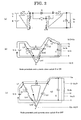
- Fig. 9 shows a general example of a conventional DC-DC converter (Boost converter).
- the DC-DC converter 90 comprises a coil (inductor) L and a switching device including, for example, a transistor or the like (simply referred to as a switch below) S connected in series between both ends of an input voltage source Vi and a parallel circuit of a load resistor R and a smoothing capacitor C connected across both ends of the switch S through a diode (rectifying device) D.
- a switching device including, for example, a transistor or the like (simply referred to as a switch below) S connected in series between both ends of an input voltage source Vi and a parallel circuit of a load resistor R and a smoothing capacitor C connected across both ends of the switch S through a diode (rectifying device) D.
- (b) is a transfer function of the DC-DC converter 90 as shown in (a).
- (c) shows ripple currents flowing through the inductor L and the diode D.
- (d) is a ripple voltage (or ripple potential) on the node a of the coil L and the diode D.
- (e) is a voltage on the coil L.
- ripple currents as shown in Fig. 9 (c) flow in response to ON/OFF operation of the switch S. That is, the ripple current flowing through the coil L is generally triangular. The amplitude of the triangular ripple current is proportional to the ON time of the switch S. And the energy stored in the coil L during the ON time of the switch S is supplied to the load R through the diode D during the OFF time of the switch S. In other words, it is possible to supply a desired voltage to load R by controlling the ON time of the switch S in response to the voltage Vi of the input voltage source.
- the ripple current in the coil L unavoidably accompanies with large noise at the switching frequency of the switch S as well as harmonic frequencies in the multiple times of the switching frequency.
- Such triangular ripple current provides a relatively low noise level as compared with, for example, a rectangular pulses but is not acceptable as a power supply for planet exploring space crafts in which highly sensitive observation equipment for observing very weak electric and/or magnetic field are installed.
- the present invention was made in consideration of the above circumstances and it is a primary object of the present invention to provide a DC-DC converter that is simple in circuit construction and capable of supplying a desired step-up output voltage that is non-inverted or has the same polarity as the input voltage.
- the DC-DC converter includes a series connection of an input inductance and a switching device connected between positive and negative terminals of an input voltage source and a load connected to the node of the input inductor and the switching device through a rectifying device for converting and outputting to the load a desired voltage of the same polarity as the input voltage source, further comprising:
- the DC-DC converter employs the following unique construction. That is, the DC-DC converter includes a series circuit of an input inductor and a switching device connected between positive and negative terminals of an input voltage source and a load connected to the node of the switching device and the input inductor through a rectifying device for converting and outputting a desired step-up voltage to the load a desired step-up voltage of the same polarity as the input voltage source, further comprising:
- the DC-DC converter according to the present invention exhibits the following unique advantages. That is, the construction is simple because mutually magnetically coupled input and output inductors as well as the intermediate inductors are only added to the conventional DC-DC converter. And it exhibits low noise by significantly reducing or essentially eliminating ripple currents in the input and output inductors. Moreover, since the input, output and intermediate inductors are magnetically coupled to equalize terminal voltages thereacross, a single transformer may be used to configure these inductors by winding coils on a common magnetic core. As a result, it finds particularly preferable applications as a power supply for planet exploration space crafts that absolutely require a stabilized low noise output voltage from a fluctuating input voltage source.
- Fig. 1 is a circuit schematic to illustrate the construction of the DC-DC converter.
- Fig. 1 (b) is the transfer function.
- Fig. 1 (c1) ⁇ (c4) shows current waveforms through a plurality of coils (inductors) constituting the DC-DC converter.
- Fig. 1 (d) shows ripple potential waveforms on various portions of the circuit as shown in Fig. 1 (a) .
- Fig. 1 (e) shows voltages across various coils.
- the DC-DC converter 10 comprises an input voltage source E such as, for example, a solar panels, an input coil (inductor) L1, a first intermediate capacitor C1 and a first intermediate coil Lm1 connected in series between positive and negative terminals of the input voltage source E, a switch (switching device) S and a second intermediate coil Lm2 connected in series between a node a of the input coil L1 and the first intermediate capacitor C1 and the negative terminal (-) of the input voltage source E, a second intermediate capacitor C2, an output coil L2 and a load (parallel connection of a resistor r and a smoothing capacitor C) connected in series across the second intermediate coil Lm2, and a diode (rectifying device) D connected between the node a and a node c of the second intermediate capacitor C2 and the output coil L2.
- E such as, for example, a solar panels
- an input coil (inductor) L1 an input coil (inductor) L1
- Fig. 1 (c1) ⁇ (c4) illustrate approximate waveforms of the ripple currents through the input coil L1, the first intermediate coil Lm1, the second intermediate coil Lm2 and the output coil L2 under different coupling conditions between these coils. That is, Fig. 1 (c1) illustrates ripple currents through the input coil L1, the first intermediate coil Lm1, the output coil L2 and the second intermediate coil Lm2 in case of no coupling between these coils from left to right in the drawing, respectively. They indicate in this case that all of the ripple currents through these coils L1, Lm1, L2 and Lm2 are large and triangular. Fig.
- Fig. 2 is the same circuit schematic as shown in Fig. 1 (a) showing the construction of the DC-DC converter 10 according to the present invention.
- Fig. 2 (b) shows currents flowing through the respective coils L1, L2, Lm1, Lm2, the capacitors C1, C2 and the load R as well as potentials on the nodes a - d when the switch S is ON.
- Fig. 2 (c) are currents through the respective coils L1, L2, Lm1, Lm2, the capacitors C1, C2 and the load R as well as potentials on the nodes a - d when the switch S is OFF.
- Fig. 2 (b) When the switch S is ON, exciting currents flow through all of the coils L1, L2, Lm1 and Lm2 as indicated by dotted lines in the drawing, thereby providing an output current through the load R from the input voltage source E.
- the current through the first intermediate capacitor C1 is in the discharging direction during the former half and in the charging direction during the latter half.
- the current through the second intermediate capacitor C2 is in the discharging direction.
- a releasing current flows from the input voltage source E through all of the coils L1, L2, Lm1 and Lm2 to provide an output current into the load R by way of the diode D.
- the direction of the current through the first intermediate capacitor C1 is in the charging direction during the former half, while in the discharging direction during the charging direction.
- the current through the second intermediate capacitor C2 is in the charging direction.
- the current is increasing (positive going) when the switch S is ON, while decreasing (negative going) when the switch S is OFF, thereby developing a triangular wave (note that the current is not a pulse wave, i.e., a rectangular wave) .
- the operation of the DC-DC converter 10 according to the present invention will be analyzed hereunder.
- the switch S is an ideal switch
- the diode D is also an ideal diode
- time durations when the switch S is ON and OFF are referred to as ton toff, respectively.
- each of the first intermediate capacitor C1 and the second intermediate capacitor C2 has sufficiently low impedance at the switching frequency of the switch S (i. e., these capacitors C1 and C2 have sufficiently large capacitance) and the first and second intermediate capacitors C1 and C2 can be considered as power sources having voltages equal to the voltage Vi of the input voltage source E and the voltage Vo of the output voltage, respectively.
- Va 1 / L ⁇ 1 + 1 / Lm ⁇ 1 / 1 / L ⁇ 1 + 1 / Lm ⁇ 1 + 1 / L ⁇ 2 + 1 / Lm ⁇ 2 ⁇ Vi ⁇ Vi / 2
- Vb - 1 / L ⁇ 2 + 1 / Lm ⁇ 2 / 1 / L ⁇ 1 + 1 / Lm ⁇ 1 + 1 / L ⁇ 2 + 1 / Lm ⁇ 2 ⁇ Vi ⁇ Vi ⁇ - Vi / 2
- Vc 1 / L ⁇ 1 + 1 / Lm ⁇ 1 / 1 / L ⁇ 1 + 1 / Lm ⁇ 1 + 1 / Lm ⁇ 2 + 1 / Lm ⁇ 2 ⁇ Vi +
- VL ⁇ 1 1 / L ⁇ 2 + 1 / Lm ⁇ 2 / 1 / L ⁇ 1 + 1 / Lm ⁇ 1 + 1 / L ⁇ 2 + 1 / Lm ⁇ 2 ⁇ Vi ⁇ Vi / 2
- VLm ⁇ 2 1 / L ⁇ 2 + 1 / Lm ⁇ 2 / 1 / L ⁇ 1 + 1 / Lm ⁇ 1 + 1 / L ⁇ 2 + 1 / Lm ⁇ 2 ⁇ Vi ⁇ Vi / 2
- VL ⁇ 2 1 / L ⁇ 1 + 1 / Lm ⁇ 1 / 1 / L ⁇ 1 + 1 / Lm ⁇ 1 + 1 / L ⁇ 2 + 1 / Lm ⁇ 2 ⁇ Vi ⁇ Vi / 2
- VL ⁇ 2 1 / L ⁇ 1 + 1 / Lm ⁇ 1 / 1 / L ⁇ 1 + 1 / Lm ⁇ 1 + 1 / Lm ⁇ 2 + 1 /
- Va ⁇ Vd Potentials (Va ⁇ Vd) on the respective nodes a ⁇ d are given by the following mathematical expressions.
- Va 1 / L ⁇ 1 + 1 / Lm ⁇ 1 ⁇ Vi + 1 / L ⁇ 2 + 1 / Lm ⁇ 2 ⁇ Vo / 1 / L ⁇ 1 + 1 / Lm ⁇ 1 + 1 / L ⁇ 2 + 1 / Lm ⁇ 2 ⁇ Vi + Vo / 2
- VL1 ⁇ VLm2 Voltages (VL1 ⁇ VLm2) across the respective coils L1 ⁇ Lm2 are given by the following mathematical expressions.
- VL ⁇ 1 - 1 / L ⁇ 2 + 1 / Lm ⁇ 2 / 1 / L ⁇ 1 + 1 / Lm ⁇ 1 + 1 / L ⁇ 2 + 1 / Lm ⁇ 2 ⁇ Vo - Vi ⁇ - Vo - Vi / 2
- the DC-DC converter 10 is capable of operating as a voltage step-up converter.
- the DC-DC converter 10 is capable of operating as a voltage step-up DC-DC converter in which the ripple currents through the input coil L1 and the output coil L2 are triangular.
- Fig. 3 (a) illustrates the two coils (namely input coil L1 and output coil L2) in the DC-DC converter circuit, ripple currents through these coils and voltages thereacross. If there are two coils L1 and L2 in the circuit that develop equal voltage across these coils as illustrated in Fig. 3 (a) and the coils L1 and L2 are coupled in the same polarity as shown in Fig. 3 (b) , these two coils L1 and L2 can be represented as the equivalent circuit as illustrated in Fig. 3 (c) .
- the coupling factor and the winding ratio of these two coils L1 and L2 satisfy the relationship as illustrated in Fig. 3 (d) (1), the ripple currents through these coils can be reduced to one half as compared to those before coupling. If the coupling factor and the winding ratio are of the relationship as illustrated in Fig. 3 (e) (2), the ripple current through the coil L1 remain unchanged from that before coupling but the ripple current through the coil L2 becomes zero (i. e., zero ripple). On the other hand, if the coupling factor and the winding ratio of the coils L1 and L2 are of the relationship as illustrated in Fig. 3 (f) (3), the ripple current through the coil L1 becomes zero, while the ripple current through the coil L2 remains unchanged from that before coupling.
- ripple current waveforms for suppressing the ripple current through only the input coil L1 by coupling only the input coil L1 and the first intermediate coil Lm1, the ripple current through only the output coil L2 by coupling only the output coil L2 and the second intermediate coil Lm2 and ripple currents through both of the input coil L1 and the output coil L2 by coupling the input coil L1 and the first intermediate coil Lm1 as well as the output coil L2 and the second intermediate coil Lm2.
- the coils to be coupled may be interchanged to have the similar result, i. e. , by coupling the input coil L1 and the second intermediate coil Lm2 and also the output coil L2 and the first intermediate coil Lm1.
- Fig. 4 shows a circuit schematic of a practical example of a DC-DC converter apparatus according to the present invention.
- the DC-DC converter apparatus 40 is designed to supply a stabilized step-up voltage to a load 46 such as an electrical/electronic circuit, another DC-DC converter, a battery or the like by the DC-DC converter 42 according to the present invention to which an unstable DC voltage from an input DC voltage source 44 is applied from a battery, a solar panel or the like.
- ON time of the switch S of the DC-DC converter 42 is controlled by a feedback control circuit 48 for providing a feedback so that a manner that the output voltage to the load 46 remains within a specified voltage range.
- the input coil L1 and the first intermediate coil Lm1 as well as the output coil L2 and the second intermediate coil Lm2 are properly magnetically coupled for significantly reducing the ripple currents through the input coil L1 and the output coil L2 or making such ripple currents substantially zero.
- the DC-DC converter apparatus 40 as shown in Fig. 4 comprises the DC-DC converter 42 including the input DC voltage source 42, the input coil L1, the output coil L2, intermediate coils Lm1, Lm2 and intermediate capacitors C1, C2, the load 46 including the load resistor R and the output (or smoothing) capacitor C and the feedback control circuit 48 for controlling the ON time of the switch by feeding back the output voltage across the load 46.
- Fig. 5 and Fig. 6 show operation waveforms that are simulation results of the ripple currents through the input coil L1 and the output coil L2 of the DC-DC converter apparatus 40 under the following zero ripple current conditions:
- Fig. 5 (a) - (h) illustrate operational waveforms in case of no coupling between the coils L1 ⁇ Lm2 of the DC-DC converter apparatus 40 as shown in Fig. 4 .
- Fig. 5 (a) ⁇ (d) are voltage waveforms across the coils L1, L2, Lm1 and Lm2, while Fig. 5 (e) - (h) are current waveforms through these coils, respectively. It is understood that the voltages across all of these coils L1 ⁇ Lm2 are equal and are Vi/2 ⁇ 60V when the switch S is ON and - (Vo - Vi)/2 ⁇ - 35V when the switch S is OFF.
- FIG. 6 (a) - (h) illustrate operation waveforms in case of coupling between the input coil L1 and the first intermediate coil Lm1 as well as between the output coil L2 and the second intermediate coil Lm2 of the DC-DC converter apparatus 40 as shown in Fig. 4 with the following coupling conditions.
- Fig. 6 (a) - (h) are voltage and current waveforms across and through the coils L1, L2, Lm1 and Lm2, respectively. Winding ratio:
- the voltages across all of the coils L1 ⁇ Lm2 are equal and are Vi/2 ⁇ 60V when the switch S is ON and - (Vo - Vi)/2 ⁇ - 35V when the switch S is OFF.
- the use of the DC-DC converter according to the present invention enables to reduce the ripple currents through the input coil L1 and the output coil L2 essentially zero, thereby significantly reducing noise as illustrated in Fig. 6 (e) and (f) .
- high electromagnetic adaptive performance helps to reduce the size of the filter to be added, thereby making the DC-DC converter compact.
- Fig. 7 shows a circuit schematic of another example of the DC-DC converter apparatus according to the present invention.
- the DC-Dc converter apparatus 70 comprises a DC-DC converter 72, a DC input voltage source 74, a load 76 and a feedback control circuit 78.
- the DC-DC converter apparatus 70 differs from the DC-DC converter apparatus 40 as shown in Fig. 4 in that the switch S of the DC-DC converter 72 comprises a bipolar transistor T and all other circuit configurations are essentially the same.
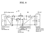
- Fig. 8 shows a circuit schematic of still another example of the DC-DC converter apparatus according to the present invention.
- This DC-DC converter apparatus 80 comprises a DC-DC converter 82, a DC input voltage source 84, a load 86 and a feedback control circuit 88.
- the DC-DC converter apparatus 80 is similar to the DC-DC converter apparatus 40, 70 as shown respectively in Figs. 4 and 7 , it differs in the use of power MOS FETs (abbreviated to MT) in place of the switch S and the diode D.
- a diode connected in parallel with each power MOSFET represents a parasitic diode.
- the output voltage is fed back by the feedback control circuit 88 by controlling ON time of the switch MT so that the output voltage is within a predetermined voltage range. Power loss of the power MOSFET can be reduced by turning ON the power MOSFET replacing the diode D in the OFF time of the switch MT (synchronous rectifying).
- the DC-DC converter according to the present invention having the particular construction and exhibiting unique advantages as described hereinabove finds wide applications. It can be applied to a power supply system and apparatus in which low noise is essential, such as a power supply system and apparatus that receives an input power from a solar panels, a power supply system and apparatus that receives an input power from a battery, a battery charging/discharging system and apparatus, or the like.
Landscapes
- Engineering & Computer Science (AREA)
- Power Engineering (AREA)
- Dc-Dc Converters (AREA)
- Control Of Electrical Variables (AREA)
- Photovoltaic Devices (AREA)
Applications Claiming Priority (1)
| Application Number | Priority Date | Filing Date | Title |
|---|---|---|---|
| JP2007259402A JP2009089564A (ja) | 2007-10-03 | 2007-10-03 | Dc/dcコンバータ |
Publications (2)
| Publication Number | Publication Date |
|---|---|
| EP2045903A2 true EP2045903A2 (de) | 2009-04-08 |
| EP2045903A3 EP2045903A3 (de) | 2010-06-30 |
Family
ID=40257509
Family Applications (1)
| Application Number | Title | Priority Date | Filing Date |
|---|---|---|---|
| EP08253227A Withdrawn EP2045903A3 (de) | 2007-10-03 | 2008-10-03 | Gleichspannungswandler |
Country Status (3)
| Country | Link |
|---|---|
| US (1) | US20090091952A1 (de) |
| EP (1) | EP2045903A3 (de) |
| JP (1) | JP2009089564A (de) |
Cited By (3)
| Publication number | Priority date | Publication date | Assignee | Title |
|---|---|---|---|---|
| WO2012172472A1 (en) * | 2011-06-17 | 2012-12-20 | Koninklijke Philips Electronics N.V. | Single switch driver device having lc filter, for driving a load, in particular an led unit |
| CN103490621A (zh) * | 2013-09-16 | 2014-01-01 | 华南理工大学 | 一种宽增益buck-boost变换器 |
| CN103490615A (zh) * | 2013-09-16 | 2014-01-01 | 华南理工大学 | 一种宽增益zeta变换器 |
Families Citing this family (5)
| Publication number | Priority date | Publication date | Assignee | Title |
|---|---|---|---|---|
| TWI399018B (zh) * | 2009-08-21 | 2013-06-11 | Ching Tsai Pan | 電流漣波消除電路 |
| CN106849670B (zh) * | 2017-03-10 | 2019-11-22 | 广州金升阳科技有限公司 | 一种反激式开关电源 |
| CN110323940B (zh) * | 2018-03-29 | 2020-10-30 | 台达电子工业股份有限公司 | 直流变换器、直流变换器模组及其连接方法 |
| CN110460035B (zh) * | 2019-08-30 | 2021-03-09 | 北方工业大学 | 基于鲁棒扰动观测器的dc-dc变换器动态补偿方法及系统 |
| US11316430B2 (en) | 2020-03-30 | 2022-04-26 | Qatar University | DC to DC switched inductor boost converter |
Citations (1)
| Publication number | Priority date | Publication date | Assignee | Title |
|---|---|---|---|---|
| JP2007259402A (ja) | 2006-02-22 | 2007-10-04 | Ntt Docomo Inc | 無線タグ判定システム及び無線タグ判定方法 |
Family Cites Families (2)
| Publication number | Priority date | Publication date | Assignee | Title |
|---|---|---|---|---|
| JPH04364358A (ja) * | 1991-06-10 | 1992-12-16 | Sumitomo Metal Ind Ltd | Dc−dcコンバータ |
| US6437999B1 (en) * | 2001-05-12 | 2002-08-20 | Technical Witts, Inc. | Power electronic circuits with ripple current cancellation |
-
2007
- 2007-10-03 JP JP2007259402A patent/JP2009089564A/ja active Pending
-
2008
- 2008-10-03 EP EP08253227A patent/EP2045903A3/de not_active Withdrawn
- 2008-10-03 US US12/244,932 patent/US20090091952A1/en not_active Abandoned
Patent Citations (1)
| Publication number | Priority date | Publication date | Assignee | Title |
|---|---|---|---|---|
| JP2007259402A (ja) | 2006-02-22 | 2007-10-04 | Ntt Docomo Inc | 無線タグ判定システム及び無線タグ判定方法 |
Cited By (8)
| Publication number | Priority date | Publication date | Assignee | Title |
|---|---|---|---|---|
| WO2012172472A1 (en) * | 2011-06-17 | 2012-12-20 | Koninklijke Philips Electronics N.V. | Single switch driver device having lc filter, for driving a load, in particular an led unit |
| CN103609198A (zh) * | 2011-06-17 | 2014-02-26 | 皇家飞利浦有限公司 | 用于驱动具体为led单元的负载的具有lc滤波器的单开关驱动器装置 |
| US9210749B2 (en) | 2011-06-17 | 2015-12-08 | Koninklijke Philips N.V. | Single switch driver device having LC filter for driving an LED unit |
| CN103609198B (zh) * | 2011-06-17 | 2016-10-19 | 皇家飞利浦有限公司 | 用于驱动负载的具有lc滤波器的单开关驱动器 |
| CN103490621A (zh) * | 2013-09-16 | 2014-01-01 | 华南理工大学 | 一种宽增益buck-boost变换器 |
| CN103490615A (zh) * | 2013-09-16 | 2014-01-01 | 华南理工大学 | 一种宽增益zeta变换器 |
| CN103490621B (zh) * | 2013-09-16 | 2016-01-20 | 华南理工大学 | 一种宽增益buck-boost变换器 |
| CN103490615B (zh) * | 2013-09-16 | 2016-01-20 | 华南理工大学 | 一种宽增益zeta变换器 |
Also Published As
| Publication number | Publication date |
|---|---|
| US20090091952A1 (en) | 2009-04-09 |
| JP2009089564A (ja) | 2009-04-23 |
| EP2045903A3 (de) | 2010-06-30 |
Similar Documents
| Publication | Publication Date | Title |
|---|---|---|
| EP2012416A1 (de) | Gleichspannungswandler | |
| EP2045903A2 (de) | Gleichspannungswandler | |
| USRE40907E1 (en) | Ripple cancellation circuit for ultra-low-noise power supplies | |
| EP1084531B1 (de) | Bidirektionaler ac/dc-spannungsregler | |
| US6232752B1 (en) | DC/DC converter with synchronous switching regulation | |
| US6549436B1 (en) | Integrated magnetic converter circuit and method with improved filtering | |
| EP1687888B1 (de) | Verfahren zur eingangsstromregelung und aktivleistungsfilter mit eingangsspannungs-vorwärtskopplung und ausgangslast-vorwärtskopplung | |
| EP2526615B1 (de) | Leistungsumwandlung mit nullspannungsschaltung | |
| US8754618B2 (en) | Control method for multi-phase DC-DC controller and multi-phase DC-DC controller | |
| JPH04351465A (ja) | Dc・dcコンバータ | |
| EP1427093A1 (de) | Gleichstrom-gleichstrom-wandler mit mehreren ausgängen | |
| US20030201761A1 (en) | Method and circuit for scaling and balancing input and output currents in a multi-phase DC-DC converter using different input voltages | |
| US20030142519A1 (en) | Synthetic ripple regulator | |
| DE102009041217A1 (de) | Spannungswandler und Verfahren zur Spannungswandlung | |
| JP5130542B2 (ja) | 降圧型スイッチングdc/dcコンバータ | |
| CA2227747A1 (en) | Buck regulator with plural outputs | |
| US4910653A (en) | Power converter with cascaded output transformers | |
| US6252383B1 (en) | Buck and boost power converters with non-pulsating input and output terminal currents | |
| US8817491B2 (en) | Electric power conversion system having an adaptable transformer turns ratio for improved efficiency | |
| US20020074977A1 (en) | Multi-output DC-DC converter and electronic apparatus using the same | |
| US20070041133A1 (en) | Switch mode power supply apparatus with multiple regulated outputs and a single feedback loop | |
| US20250047200A1 (en) | Single inductor multiple output regulator | |
| JPH07327366A (ja) | 電源装置 | |
| WO2007148886A1 (en) | Asymmetric half bridge converter | |
| KR102003688B1 (ko) | 다중 입력 싱글 인덕터 벅 부스트 컨버터 |
Legal Events
| Date | Code | Title | Description |
|---|---|---|---|
| PUAI | Public reference made under article 153(3) epc to a published international application that has entered the european phase |
Free format text: ORIGINAL CODE: 0009012 |
|
| AK | Designated contracting states |
Kind code of ref document: A2 Designated state(s): AT BE BG CH CY CZ DE DK EE ES FI FR GB GR HR HU IE IS IT LI LT LU LV MC MT NL NO PL PT RO SE SI SK TR |
|
| AX | Request for extension of the european patent |
Extension state: AL BA MK RS |
|
| PUAL | Search report despatched |
Free format text: ORIGINAL CODE: 0009013 |
|
| AK | Designated contracting states |
Kind code of ref document: A3 Designated state(s): AT BE BG CH CY CZ DE DK EE ES FI FR GB GR HR HU IE IS IT LI LT LU LV MC MT NL NO PL PT RO SE SI SK TR |
|
| AX | Request for extension of the european patent |
Extension state: AL BA MK RS |
|
| AKY | No designation fees paid | ||
| REG | Reference to a national code |
Ref country code: DE Ref legal event code: R108 Effective date: 20110208 Ref country code: DE Ref legal event code: 8566 |
|
| STAA | Information on the status of an ep patent application or granted ep patent |
Free format text: STATUS: THE APPLICATION IS DEEMED TO BE WITHDRAWN |
|
| 18D | Application deemed to be withdrawn |
Effective date: 20101230 |