EP2045880B1 - A connector in the field of telecommunications - Google Patents
A connector in the field of telecommunications Download PDFInfo
- Publication number
- EP2045880B1 EP2045880B1 EP07019489A EP07019489A EP2045880B1 EP 2045880 B1 EP2045880 B1 EP 2045880B1 EP 07019489 A EP07019489 A EP 07019489A EP 07019489 A EP07019489 A EP 07019489A EP 2045880 B1 EP2045880 B1 EP 2045880B1
- Authority
- EP
- European Patent Office
- Prior art keywords
- connector
- wires
- contacts
- wire
- cable
- Prior art date
- Legal status (The legal status is an assumption and is not a legal conclusion. Google has not performed a legal analysis and makes no representation as to the accuracy of the status listed.)
- Not-in-force
Links
- 238000009413 insulation Methods 0.000 description 18
- 230000005540 biological transmission Effects 0.000 description 7
- 230000000694 effects Effects 0.000 description 5
- 239000011888 foil Substances 0.000 description 5
- 238000005452 bending Methods 0.000 description 4
- 230000000295 complement effect Effects 0.000 description 4
- 238000006073 displacement reaction Methods 0.000 description 4
- 238000003780 insertion Methods 0.000 description 3
- 230000037431 insertion Effects 0.000 description 3
- 239000004020 conductor Substances 0.000 description 2
- 238000010292 electrical insulation Methods 0.000 description 2
- 238000005516 engineering process Methods 0.000 description 2
- 230000002452 interceptive effect Effects 0.000 description 2
- 239000002184 metal Substances 0.000 description 2
- 229910052751 metal Inorganic materials 0.000 description 2
- 238000005192 partition Methods 0.000 description 2
- 238000000926 separation method Methods 0.000 description 2
- 101150012579 ADSL gene Proteins 0.000 description 1
- 102100020775 Adenylosuccinate lyase Human genes 0.000 description 1
- 108700040193 Adenylosuccinate lyases Proteins 0.000 description 1
- RYGMFSIKBFXOCR-UHFFFAOYSA-N Copper Chemical compound [Cu] RYGMFSIKBFXOCR-UHFFFAOYSA-N 0.000 description 1
- 230000009286 beneficial effect Effects 0.000 description 1
- 238000004891 communication Methods 0.000 description 1
- 229910052802 copper Inorganic materials 0.000 description 1
- 239000010949 copper Substances 0.000 description 1
- 230000006866 deterioration Effects 0.000 description 1
- 238000012986 modification Methods 0.000 description 1
- 230000004048 modification Effects 0.000 description 1
- 238000012545 processing Methods 0.000 description 1
- 238000012360 testing method Methods 0.000 description 1
- 238000010618 wire wrap Methods 0.000 description 1
Images


Classifications
-
- H—ELECTRICITY
- H01—ELECTRIC ELEMENTS
- H01R—ELECTRICALLY-CONDUCTIVE CONNECTIONS; STRUCTURAL ASSOCIATIONS OF A PLURALITY OF MUTUALLY-INSULATED ELECTRICAL CONNECTING ELEMENTS; COUPLING DEVICES; CURRENT COLLECTORS
- H01R4/00—Electrically-conductive connections between two or more conductive members in direct contact, i.e. touching one another; Means for effecting or maintaining such contact; Electrically-conductive connections having two or more spaced connecting locations for conductors and using contact members penetrating insulation
- H01R4/24—Connections using contact members penetrating or cutting insulation or cable strands
- H01R4/2416—Connections using contact members penetrating or cutting insulation or cable strands the contact members having insulation-cutting edges, e.g. of tuning fork type
- H01R4/242—Connections using contact members penetrating or cutting insulation or cable strands the contact members having insulation-cutting edges, e.g. of tuning fork type the contact members being plates having a single slot
- H01R4/2425—Flat plates, e.g. multi-layered flat plates
- H01R4/2429—Flat plates, e.g. multi-layered flat plates mounted in an insulating base
- H01R4/2433—Flat plates, e.g. multi-layered flat plates mounted in an insulating base one part of the base being movable to push the cable into the slot
-
- A—HUMAN NECESSITIES
- A61—MEDICAL OR VETERINARY SCIENCE; HYGIENE
- A61P—SPECIFIC THERAPEUTIC ACTIVITY OF CHEMICAL COMPOUNDS OR MEDICINAL PREPARATIONS
- A61P35/00—Antineoplastic agents
-
- H—ELECTRICITY
- H01—ELECTRIC ELEMENTS
- H01R—ELECTRICALLY-CONDUCTIVE CONNECTIONS; STRUCTURAL ASSOCIATIONS OF A PLURALITY OF MUTUALLY-INSULATED ELECTRICAL CONNECTING ELEMENTS; COUPLING DEVICES; CURRENT COLLECTORS
- H01R13/00—Details of coupling devices of the kinds covered by groups H01R12/70 or H01R24/00 - H01R33/00
- H01R13/58—Means for relieving strain on wire connection, e.g. cord grip, for avoiding loosening of connections between wires and terminals within a coupling device terminating a cable
- H01R13/5841—Means for relieving strain on wire connection, e.g. cord grip, for avoiding loosening of connections between wires and terminals within a coupling device terminating a cable allowing different orientations of the cable with respect to the coupling direction
-
- H—ELECTRICITY
- H01—ELECTRIC ELEMENTS
- H01R—ELECTRICALLY-CONDUCTIVE CONNECTIONS; STRUCTURAL ASSOCIATIONS OF A PLURALITY OF MUTUALLY-INSULATED ELECTRICAL CONNECTING ELEMENTS; COUPLING DEVICES; CURRENT COLLECTORS
- H01R2201/00—Connectors or connections adapted for particular applications
- H01R2201/04—Connectors or connections adapted for particular applications for network, e.g. LAN connectors
Definitions
- the invention relates to a connector in the field of telecommunications providing an increased versatility regarding the connection of wires.
- connections are established by telecommunications and/or data lines. These connections can be made by wires, for example copper wires.
- Plural wires can be integrated with a cable and can be put together at a connector, such as a plug or a socket. By connecting two connectors of this type with each other, plural connections between the wires, which are connected with each of the connectors, are established.
- a type of connection can also be used in networks, such as local area networks, for any connections between devices being part of the network.
- Such a network may have an outlet in a work area and a patch panel in a data room.
- Connectors may be mounted in the outlets and/or the patch panels. Typical connectors are described in ICE 60603-7.
- cross-talk describes an effect in which the contacts of a telecommunications module act as small antennae, which transmit an interfering signal to adjacent contacts.
- the interfering signals are transmitted by a pair of wires and, therefore, by a pair of adjacent contacts.
- cross-talk between the contacts of a single pair is not an issue.
- cross-talk between the contacts of adjacent pairs should be reduced as far as possible.
- the contacts in conventional jack connectors may be in close proximity to one another. If these jack connectors are used in high performance communication systems, cross-talk between adjacent conductor pairs may occur. As regards cross-talk between pairs of wires, such cross-talk is reduced by twisting the pairs. Moreover, plural twisted pairs, which may be integrated in a cable, may be shielded from each other and/or twisted themselves. The shielding of an individual wire pair may be formed by a foil shielding, in other words, a metal foil or metalized foil formed around a twisted pair. As an alternative, individual pairs may be shielded by a braid. Finally, cross-talk between adjacent cables may be reduced by shielding the cables. In this context, the shielding of individual wire pairs may be formed as a foil shielding, and the shielding of the cable may be formed by a braid. Moreover, the cable may additionally have a drain wire.
- US 6,267,617 B1 describes a low current outlet having contact pins and an organizer cap, which, on being fixed to a base, establishes electrical contact between wires and the contact pins.
- the cap is provided with wire guides extending parallel to each other.
- US 2004/0229517 A1 is related to a jack having a terminal housing with a base through which one or more wire management tunnels extend.
- the tunnels may have openings facing opposite directions.
- US 5,957,720 A describes a socket having a connecting pusher which may be pushed by jaws fixed on the socket so as to engage wires arranged in the connecting pusher with insulation displacement contacts.
- US 6,793,515 B1 is related to a connecting cable having a cable manager with guides adapted to accommodate individual wires.
- EP 0 23 397 A1 discloses a connector with a plurality of contacts with which wires are connectable inside the connector and at least three wire openings, the wire openings are exposed in at least three different directions.
- the invention provides a connector in the field of telecommunications which has an improved versatility regarding the connection of wires.
- the connectors described herein have contacts with which wires are connectable.
- the wires are connectable with the contacts "inside" the connector, i.e. the interfaces between the wires and the connectors may, during use of the connector, be fully “hidden” and/or fully surrounded by parts of the connector's housing.
- Those portions of the contacts, where wires are connectable may, for example, be formed as insulation displacement contacts, as wire wrap contacts or in any other suitable manner.
- the contacts may have portions exposed outside the connector, so that a complementary connector also having contacts is connectable with the connector such that the contacts of the connectors are in electrical contact.
- the connector described herein may be a RJ45 type connector or a connector in line with ICE 60603-7.
- the wires which are connectable with the contacts of the connector, may be integrated with a cable and the connector described herein has at least three wire openings for inserting at least two wires through each opening.
- the wire openings are adapted to accommodate two wires, i.e. a pair of wires, which may be twisted, four wires, i.e. the two pairs, or more wires.
- at least one wire opening may be adapted to accommodate a cable, with which the wires are integrated.
- a cable may, for example, have four twisted wire pairs integrated therewith.
- the wire pairs may be shielded from each other, and a shielding as well as an electrical insulation may be provided around the wire pairs.
- the connectors described herein may be advantageous in that the "complete" cable may be inserted through a wire opening and guided in a suitable cable guide.
- a “complete” cable may have plural twisted wire pairs, for example, four wire pairs, shielding for the individual pairs and/or the cable shielding around all pairs, possibly a drain wire and, for example, as the outermost layer, an insulation.
- a wire opening is adapted to accommodate a "complete” cable, it can substantially be ruled out that the shielding and electrical insulation needs to be removed from the cable until the location, where the wires are separated from each other to individually connect them with contacts.
- cables, as described above may be formed “substantially balanced” by providing twisted wire pairs, twisting the twisted pairs themselves and providing appropriate shielding.
- This substantially balanced state is disturbed when the individual pairs, or even wires, are separated from each other.
- the desired, substantially balanced state may substantially be maintained if the wire openings are adapted to accommodate a "complete" cable.
- One or more wire openings may be adapted to allow the insertion of fewer wires then wires integrated with a cable.
- the wire openings which may, for example, be smaller in cross-section than the cable, may then allow to remove the insulation and shielding of cable and the separation of wires or wire pairs from each other at a defined location.
- insulation and shielding of a cable may be removed at the end of the cable for a certain distance, and the wires or wire pairs may be separated from each other and inserted into the connector, through the one or more wire openings, individually.
- a wire pair possibly together with its individual shielding, such as a foil shielding may be inserted into the connector through the one or more openings. This may be advantageous as the twisted wire pair may maintain the twisted state and may also be guided in this state, which may be beneficial from the viewpoint of shielding.
- the wire openings are exposed on an outside of the connector distal from the contacts.
- the wire openings can also be said to be exposed to a side where an incoming cable is to be connected with the connector. This side may be described to be generally opposite a side where a complementary connector is to be inserted.
- the wire openings exposed on the outside of the connector may be described to be remote or distal from the contacts.
- any connections between individual wires and the contacts may be formed within the connector.
- the wire openings is formed by an opening through hole or bore that serves to allow the insertion of wires or the cable in a certain direction at that point, where the opening, through hole or bore is formed.
- the wire openings are orientated in at least three different directions.
- the wire openings are exposed on the outside of the connector.
- a cable or wire may be inserted into an appropriate opening from outside the connector.
- cables arriving from underneath the floor, under a ceiling, in ducts or from behind panels may advantageously be inserted into the connector with their orientation being substantially maintained up to a position inside the connector. This may minimize the occurrence of undesired bendings of the cable, which is particularly advantageous when insulation and/or shielding have been removed from the cable. This is because in this state, i.e. with insulation and/or shielding removed, the desired arrangement of the wires may be difficult to maintain.
- the at least three openings may, for example, be exposed in different radial directions from a center region of the connector or a location where it is intended to disintegrate the wires of the cable and separate individual wires from each other.
- any unavoidable bending, to bring the wires into a proper orientation relative to the contacts may be done in a controlled manner, such as within the connector and by providing a defined orientation of recesses guiding the individual wires (described in more detail below) and other guides.
- the complete cable may not have to be bent at all. Rather, the necessary bending of the wires may be done at that point, where the wires are separated from each other. For example, the unavoidable bendings of the wires may be as close as possible to the contacts of the connector.
- the connector described herein may be mounted on printed circuit boards. Also in such a case, a cable may be connected with the connector as described above. As an alternative, or in addition to such a cable, a cable could be connected with conductors printed on the printed circuit board and connected with contacts of the connector.
- the printed circuit boards may be provided in active network equipment such as routers.
- the connectors may be mounted on patch panels and outlets that may be provided in walls or cable ducts.
- the wire openings may be arranged in pairs or groups of four, the openings of one pair or group being exposed in the same direction.
- the group of openings may be adapted to allow the insertion of all wires of a cable through the openings of a single group.
- substantially all wires of a cable, arriving at the connector with a particular orientation may substantially keep this orientation through the openings and up to a location inside the connector.
- the cable may arrive from any one of at least three different directions and may advantageously not have to be bent at the point of entry into the connector.
- each opening may, for example, be adapted to accommodate half or a quarter of the number of wires which are present in a cable.
- four wires i.e. two pairs can be inserted into each opening of a pair of openings.
- two wires i.e. one pair, may be inserted into each opening of a group of four openings.
- the wires may advantageously be kept spaced from each other already at their point of entry into the connector. In this manner, cross-talk may be minimized.
- a guide is formed adjacent each wire opening and has a certain extension in the direction of the wire or cable to be guided, to define the direction and shape of the wire or cable substantially throughout the extension of the guide.
- the guide may extend substantially straight, curved or angled. Wherever curves and/or angles are present, when the guide is adapted to guide the complete cable, the cable is advantageously bent as a complete cable, so that misalignments of the individual wires are unlikely, so that deterioration of the transmission performance and of the cross-talk properties may be minimized.
- the wire or cable guide may be formed by structures, such as partitions, webs and/or lugs adapted to keep individual wires or groups of wires apart from each other.
- channels which may have a closed cross-section, may be formed in the connector to guide individual wires or groups of wires to those contacts with which they are to be connected.
- the connector may have a colour coding to assist the person connecting wires with the connector in making the correct connections.
- At least one guide may be adapted to accommodate a cable with which all wires connectable with the contacts of the connector are integrated. Thus, a "complete" cable may be guided by the guide and the possibility of misarranging individual wires is particularly low. However, as indicated above, it may also be advantageous to adapt at least one guide to accommodate fewer wires, such as a single wire pair.
- the connector has a housing and at least one guide piece. At least one wire opening is be formed in the guide piece.
- both the housing and the guide piece may be designed with a specific focus on the functionality of the component.
- the housing may be designed to accommodate the contacts, the guide piece and, for example, any structures, such as latch hooks, screw openings or similar structures which allow the connector to be mounted to a patch panel, an outlet or similar surrounding as described above.
- the guide piece has wire or cable guides as mentioned above with any suitable structure, including those exemplary structures mentioned above.
- the guide piece may be adapted to be moved towards the contacts to connect the wires with the contacts. This movement and the resulting connection of wires may be effected manually so that there may be no need to provide and use specific tools.
- the guide piece not only has openings and adjacent guides but may also have at least one recess for accommodating at least one individual wire.
- the recess may be facing the contacts so that an individual wire may be accommodated in a manner to support its connection with a contact.
- the recesses that are adapted to guide individual wires may be formed of any other suitable structures for guiding individual wires, such as ribs or channels.
- the contacts may be formed as insulation displacement contacts having a contact slit, into which the wire is pushed to cut the insulation of the wire and allow the legs defining the contact slit to contact the metal part of the wire.
- the wires are accommodated in recesses, as described above, it has been found advantageous to push the wires into the contact slits in this accommodated position.
- it may be advantageous to provide at least one slot for accommodating at least one contact in the guide piece.
- the one or more slots may be used, together with the contacts accommodated therein, to guide the guide piece when it is moved towards the contacts.
- further guiding elements may be provided on the connector to guide the movement of the guide piece.
- the above-described step of pushing the wire into the contact slit while accommodated in the recess may be performed readily when at least one slot and at least one recess intersect each other.
- the guide piece may be adapted to be moved towards the contact to push the wires into the contacts.
- the housing may be provided with at least one drive piece adapted to drive the guide piece to the contacts.
- Such a drive piece may assist the operator connecting the wires with the contacts in establishing the connections.
- At least one drive piece may be particularly advantageous to form at least one drive piece as a pivotable flap having at least one projection adapted to drive the guide piece when the flap is pivoted. This allows an especially easy actuation of the drive piece to move the guide piece towards the contact. Moreover, through the action of the projection, a lever effect may be used.
- the guide piece can be moved towards the contacts relatively easily, when two projections are provided.
- Two projections may, moreover, be provided in a manner to locate at least one wire opening between two projections.
- an easy actuation of the guide piece may be combined with a ready access to the wire openings.
- connectors described herein may be provided as plugs or male connectors
- preferred embodiments of connectors may be formed as jacks or sockets, i.e. female connectors.
- FIG. 1 is a perspective rear view (i.e. from the side where the cable enters the connector) of the connector 10, partly disassembled.
- a housing 18 of the connector 10 may define a generally rectangular opening, within which contacts are exposed to allow the contacts of a complementary connector (not shown) to be electrically contacted.
- the housing may be provided with latch hooks 28 or similar structures to allow mounting the connector 10 to an appropriate surrounding.
- This may, for example, be performed by attaching the connector 10 to a panel from the rear side, so that the latch hook visible in FIG. 1 will protrude to the front side.
- the latch hook protruding through the rear wall may be hidden behind a front wall.
- a guide piece 20 having, in the embodiment shown, three openings 16 with adjacent guides 14 (one of them being formed on the underside and not visible in FIG. 1 ) may be moveable towards the contacts 12.
- a cable having a plurality of wires, with shielding and insulation around all the wires, may be inserted into either one of the cable guides 14 through the respective opening 16 visible in the figure.
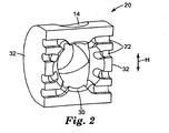
- the guide piece 20 is formed as a type of semi-cylinder with recesses 22 (see FIG. 2 ) adapted to accommodate individual wires being formed on the flat face and wire openings 16 being formed at three different positions along the curved face.
- the connector shown in FIG. 1 has two drive pieces in the form of pivotable flaps 24, each having a projection 26.
- the guide piece 20 may be placed in close proximity to the contacts 12, the pivotable flaps may be pivoted towards the guide piece 20, and the projections 26 may engaged the guide piece 20 to push it towards the contacts 12 when the pivotable flaps 24 are approaching their final position shown in FIG. 3 .
- the pivotable flaps 24 may be pivotable about an axis perpendicular to the direction in which the guide piece 20 is to be moved.
- the cable guides 14 have a certain extension from the semi-cylindrical surface visible in FIG. 1 towards the inside of the guide piece 20 visible in FIG. 2 .
- the guides 14 may have a substantially cylindrical inner wall, by which the cable may be guided.
- the guide piece 20 shown in FIG. 1 may additionally have openings formed at one or both (semicircular) side faces, i.e. those faces directed to the pivotable flaps 24.
- one or both pivotable flaps 24 may be formed with suitable openings to allow access to the above-described laterally open wire openings, which are not shown in FIG. 1 .
- the cable to be connected with the connector 10 may not only arrive at the connector 10 from the rear side, the top and the bottom, as seen in FIG. 1 , but also from one or both of the lateral sides.
- FIG. 2 shows the guide piece 20 of FIG. 1 from the side facing the contacts 12 (see FIG. 1 ).
- the cable guides 14 each terminate at approximately the same position inside the guide piece 20. At that location, the cable's insulation and shielding usually ends.
- the cable is inserted through the appropriate guide 14, and the insulation and shielding are removed and the end of the cable to expose the individual wires.
- the cable may then be arranged to allow the individual wires to be accommodated in recesses 22 visible in FIG. 2 .
- the insulation and shielding of the cable may terminate approximately at the position of the central opening 30, to which the recesses 22 extend.
- the recesses 22 each have a first portion, extending from the opening 30, which extends approximately radially from the opening 30. In other words, the first portions together have a somewhat star-like appearance. Second portions of the recesses 22 extend approximately parallel to each other. In the embodiment shown, the second portions of those recesses which are on different sides of the opening 30, but at approximately the same height along the height direction H, may be aligned with each other. However, the recesses 22 could also be arranged on a single side of the opening 30.
- the recesses 22 may have one or more flexible parts, portions and/or adaptors, to generally adapt their size to different sizes of wires.
- one or more recesses 22 may have one or more "half-pipes" having an onion-type structure and suitable to remove as many "layers" as necessary to make the recess large enough for accommodating a particular wire.
- Such flexible and/or removable parts may be made of rubber.
- the guide piece 20 After possibly removing the necessary parts of the recesses 22 and accommodating the wires therein, as described above with reference to FIG. 1 , the guide piece 20 is moved towards the contacts 12, so that each wire is pushed into a contact slit (not visible in FIG. 1 ). To allow this pushing of a wire accommodated in a recess 22 into the slit of contact 12, the guide piece 20 has, on the surface facing the viewer of FIG. 2 , a plurality of slots (not shown) for accommodating the contacts 12. The slots may intersect with the recesses 22.
- the guide piece 20 may be adapted to fit between contacts aligned along the lateral sides 32 of the guide piece 20 so that wires accommodated in the recesses 22 will also be pushed into the contacts positioned as described above.
- FIG. 3 shows the connector 10 with a cable 34 connected thereto.
- the cable 34 has been inserted from the bottom side
- the guide piece 20 has been moved towards the contacts 12 (see FIG. 1 ) and the pivotable flaps 24 have been pivoted towards each other to accommodate the guide piece 20 between them.
- the projections 26 have served to push the guide piece 20 in the above-described manner.
- that versatility of the connector 10 described herein may be advantageous in that the cable 34 could also be inserted from the top or straight from the rear.
- the wire opening 16, which is exposed at the rear side is arranged between the two projections 26.
- FIG. 4 shows a perspective view of another embodiment of a guide piece 120 which may be used in the connector 10 shown in FIGS. 1 and 3 or in another embodiment of a connector.
- the general appearance of the guide piece 120 differs from that shown in FIG. 2 in that it has the general shape of a cuboid with an extension 140 that generally corresponds to the thickest part of the semi-cylindrical shape of the guide piece 20 shown in FIG. 2 .
- openings 116 are exposed in three different directions.
- openings 116 visible in FIG. 4 at the front and rear sides are also formed at the lower side (not visible) of FIG. 4 .
- each opening 116 may, for example, be adapted to accommodate four wires, i.e. two pairs of wires.
- the insulation and shielding of a cable (not shown) with which eight wires, i.e. four wire pairs, are integrated, may end at the web 142, and the wires may be inserted through the openings 116, for example, four wires through each opening. That part of the web 142 that extends into the interior of the guide piece 120, denoted 114 in the drawing, may serve as a wire guide.
- these wire guides 114.1 and 114.2 formed on opposite sides may be extended into a partition (not shown) and/or may start at a location somewhat "inside" the guide piece 120, i.e. somewhat displaced towards the centre of the guide piece 120.
- wires of a left and right side may be advantageously separated from each other and guided.
- a web (not shown) formed across the openings (not shown) of extension 140 may be coplanar with the webs 142 visible in FIG. 4 .
- each side has, between the second 122.2 and third recess 122.3, i.e, approximately at the center of each side, an internal lug 144 protruding to the interior of the guide piece 120 and serving to separate those wires from each other, which are inserted into the recesses in front of the lug 144, on the one hand, and into the recesses behind the lug 144, on the other hand.
- four wires which may, for example, be inserted through the front and left side opening 116.1
- two wires of an upper wire pair may, for example, be inserted into recesses 122.1 and 122.2.
- the wires of a "lower" wire pair may continue at a location below the left side lug 144.1, to recesses 122.3 and 122.4 and may be inserted into these.
- each recess 122 has an entrance 146 which is somewhat narrower than the remainder of the recess 122.
- the entrances 146 may also be used to clamp wires accommodated therein. This also applies to the remainder of the recesses 122.
- the recess 122 may have an approximately circular cross-section adapted to accommodate wires having, together with their insulation, an approximately circular cross-section as well. When a wire is inserted into a recess 122, the insulation thereof may be briefly compressed, to allow the wire to pass the narrow entrance 146 and the wire then be accommodated in the recess 122. As can be seen from the recesses 122 on the right side of FIG.
- the recesses may be formed as generally rounded, V-shaped recesses towards the inside of the guide piece 120.
Landscapes
- Health & Medical Sciences (AREA)
- Chemical & Material Sciences (AREA)
- Chemical Kinetics & Catalysis (AREA)
- General Chemical & Material Sciences (AREA)
- Medicinal Chemistry (AREA)
- Nuclear Medicine, Radiotherapy & Molecular Imaging (AREA)
- Organic Chemistry (AREA)
- Pharmacology & Pharmacy (AREA)
- Life Sciences & Earth Sciences (AREA)
- Animal Behavior & Ethology (AREA)
- General Health & Medical Sciences (AREA)
- Public Health (AREA)
- Veterinary Medicine (AREA)
- Details Of Connecting Devices For Male And Female Coupling (AREA)
- Multi-Conductor Connections (AREA)
- Coupling Device And Connection With Printed Circuit (AREA)
- Connections By Means Of Piercing Elements, Nuts, Or Screws (AREA)
Priority Applications (14)
| Application Number | Priority Date | Filing Date | Title |
|---|---|---|---|
| EP07019489A EP2045880B1 (en) | 2007-10-04 | 2007-10-04 | A connector in the field of telecommunications |
| AT07019489T ATE497270T1 (de) | 2007-10-04 | 2007-10-04 | Verbinder auf dem gebiet der telekommunikation |
| ES07019489T ES2360249T3 (es) | 2007-10-04 | 2007-10-04 | Conector en el campo de las telecomunicaciones. |
| DE602007012257T DE602007012257D1 (de) | 2007-10-04 | 2007-10-04 | Verbinder auf dem Gebiet der Telekommunikation |
| PL07019489T PL2045880T3 (pl) | 2007-10-04 | 2007-10-04 | Złącze telekomunikacyjne |
| MX2010003190A MX2010003190A (es) | 2007-10-04 | 2008-09-30 | Conectador para el campo de telecomunicaciones. |
| JP2010528070A JP2010541181A (ja) | 2007-10-04 | 2008-09-30 | 電気通信技術におけるコネクタ |
| RU2010112251/07A RU2441302C2 (ru) | 2007-10-04 | 2008-09-30 | Разъем для применения в области телекоммуникаций |
| US12/680,948 US7967642B2 (en) | 2007-10-04 | 2008-09-30 | Connector in the field of telecommunications |
| TW097137553A TW200935684A (en) | 2007-10-04 | 2008-09-30 | A connector in the field of telecommunications |
| CN2008801103597A CN101821903B (zh) | 2007-10-04 | 2008-09-30 | 电信领域的连接器 |
| PCT/US2008/078258 WO2009046000A2 (en) | 2007-10-04 | 2008-09-30 | A connector in the field of telecommunications |
| BRPI0816509-2A2A BRPI0816509A2 (pt) | 2007-10-04 | 2008-09-30 | "conector no campo das telecomunicações" |
| ARP080104308A AR068717A1 (es) | 2007-10-04 | 2008-10-02 | Un conector en el campo de las telecomunicaciones |
Applications Claiming Priority (1)
| Application Number | Priority Date | Filing Date | Title |
|---|---|---|---|
| EP07019489A EP2045880B1 (en) | 2007-10-04 | 2007-10-04 | A connector in the field of telecommunications |
Publications (2)
| Publication Number | Publication Date |
|---|---|
| EP2045880A1 EP2045880A1 (en) | 2009-04-08 |
| EP2045880B1 true EP2045880B1 (en) | 2011-01-26 |
Family
ID=39111317
Family Applications (1)
| Application Number | Title | Priority Date | Filing Date |
|---|---|---|---|
| EP07019489A Not-in-force EP2045880B1 (en) | 2007-10-04 | 2007-10-04 | A connector in the field of telecommunications |
Country Status (14)
| Country | Link |
|---|---|
| US (1) | US7967642B2 (enExample) |
| EP (1) | EP2045880B1 (enExample) |
| JP (1) | JP2010541181A (enExample) |
| CN (1) | CN101821903B (enExample) |
| AR (1) | AR068717A1 (enExample) |
| AT (1) | ATE497270T1 (enExample) |
| BR (1) | BRPI0816509A2 (enExample) |
| DE (1) | DE602007012257D1 (enExample) |
| ES (1) | ES2360249T3 (enExample) |
| MX (1) | MX2010003190A (enExample) |
| PL (1) | PL2045880T3 (enExample) |
| RU (1) | RU2441302C2 (enExample) |
| TW (1) | TW200935684A (enExample) |
| WO (1) | WO2009046000A2 (enExample) |
Families Citing this family (10)
| Publication number | Priority date | Publication date | Assignee | Title |
|---|---|---|---|---|
| DE102011054563B3 (de) * | 2011-10-18 | 2013-01-24 | HARTING Electronics GmbH | Steckverbinder |
| US8961217B2 (en) | 2013-03-12 | 2015-02-24 | Carlisle Interconnect Technologies, Inc. | Electrical connector assembly with integrated latching system, strain relief, and EMI shielding |
| TWM479548U (zh) | 2014-01-08 | 2014-06-01 | Jyh Eng Technology Co Ltd | 多方進線連接器 |
| US9130283B1 (en) | 2014-02-18 | 2015-09-08 | Jyh Eng Technology Co., Ltd. | Electrical connector with multi-direction cable installation capability |
| US20170005444A1 (en) * | 2014-04-11 | 2017-01-05 | HARTING Electronics GmbH | Plug-in connector |
| US9147946B1 (en) * | 2014-05-30 | 2015-09-29 | Memie Mei Mei Wong | Electrical cable connector |
| CN106356690B (zh) * | 2016-10-28 | 2024-02-06 | 上海天诚通信技术股份有限公司 | 水晶头摆动装置 |
| JP2019125528A (ja) * | 2018-01-18 | 2019-07-25 | 株式会社オートネットワーク技術研究所 | 電線カバー、及びコネクタ |
| US12463391B2 (en) * | 2020-04-30 | 2025-11-04 | Commscope Technologies Llc | Modular telecommunications plug and method |
| WO2022093227A1 (en) * | 2020-10-29 | 2022-05-05 | Hewlett-Packard Development Company, L. P. | Cable guides |
Family Cites Families (34)
| Publication number | Priority date | Publication date | Assignee | Title |
|---|---|---|---|---|
| US4140907A (en) * | 1976-07-29 | 1979-02-20 | Nippon Telegraph And Telephone Public Corporation | Thermal-plain paper recording system |
| US4236779A (en) * | 1978-05-01 | 1980-12-02 | Bunker Ramo Corporation | EMI Shielded cable and connector assembly |
| US4711507A (en) * | 1985-10-07 | 1987-12-08 | Thomas & Betts Corporation | Electrical connector and latching apparatus therefor |
| US5192226A (en) * | 1992-05-06 | 1993-03-09 | Wang Tsan Chi | Double-output port cable assembly for notebook computers |
| US5199904A (en) * | 1992-08-06 | 1993-04-06 | Safco Corporation | Electrical offset adapter plug |
| US5413493A (en) * | 1993-01-15 | 1995-05-09 | Hubbell Incorporated | Electrical connector assembly, especially for electric vehicle |
| RU2035810C1 (ru) * | 1993-04-13 | 1995-05-20 | Малое научно-производственное предприятие "Ферро-Центр" | Сетевая штепсельная колодка с подавлением помех |
| JPH10241811A (ja) * | 1997-02-24 | 1998-09-11 | Nitto Kogyo Co Ltd | 通信用分岐アダプター |
| FR2760136B1 (fr) | 1997-02-27 | 1999-04-23 | Pouyet Sa | Prise femelle murale de type jack modulaire |
| FR2768862B1 (fr) | 1997-09-22 | 1999-12-24 | Infra Sa | Prise de courant faible a capuchon arriere organisateur |
| FR2769757B1 (fr) | 1997-10-15 | 1999-12-10 | Pouyet Sa | Prise murale au moins partiellement blindee, et procede de raccordement d'un cable electrique sur cette prise |
| EP0935314B9 (de) | 1998-02-06 | 2011-05-11 | Fred Schmitt | Steckverbinder-Gehäuse im 19 Zoll-Gerätesystem |
| US6348035B1 (en) * | 1998-09-09 | 2002-02-19 | Asahi Kogaku Kogyo Kabushiki Kaisha | Connection system for electronic endoscope |
| US6160485A (en) * | 1998-12-29 | 2000-12-12 | Applied Systems Engineering, Llc | Voltage level conditioning transceiver cable |
| DE19959823C2 (de) | 1999-12-10 | 2003-04-30 | Krone Gmbh | Verbindungskabel mit elektrischer Steckverbindung |
| US6506077B2 (en) * | 2000-07-21 | 2003-01-14 | The Siemon Company | Shielded telecommunications connector |
| DE10057869C1 (de) | 2000-11-21 | 2002-08-22 | Ria Btr Prod Gmbh | Steckverbinder für geschirmte Daten- und/oder Telekommunikations-Kabel |
| DE50211308D1 (de) * | 2001-08-20 | 2008-01-17 | Woertz Ag | Elektrische Klemme |
| DE10156251A1 (de) * | 2001-11-09 | 2003-05-22 | Ackermann Albert Gmbh Co | Elektrischer Verbinder |
| US7035112B2 (en) * | 2002-07-08 | 2006-04-25 | Aten International Co., Ltd. | Automatic switch |
| US6830488B2 (en) | 2003-05-12 | 2004-12-14 | Krone, Inc. | Modular jack with wire management |
| US7150657B2 (en) * | 2003-05-23 | 2006-12-19 | Nordx/Cdt Inc. | Wire lead guide and method for terminating a communications cable |
| TWM250195U (en) * | 2003-07-21 | 2004-11-11 | Fullyear Brother Entpr Co Ltd | Adapting base structure of computer connector |
| US20060094281A1 (en) | 2004-11-04 | 2006-05-04 | Carlyle, Inc. | Latching electrical connector assembly |
| US7182647B2 (en) * | 2004-11-24 | 2007-02-27 | Cooper Technologies Company | Visible break assembly including a window to view a power connection |
| US7112086B1 (en) | 2005-04-08 | 2006-09-26 | Hon Hai Precision Ind. Co., Ltd. | Electrical cable assembly having cable guide |
| US7641610B2 (en) * | 2005-08-09 | 2010-01-05 | Olympus Medical Systems Corporation | Endoscope electric connection device |
| PL1753093T3 (pl) | 2005-08-12 | 2009-01-30 | 3M Innovative Properties Co | Łącznik telekomunikacyjny |
| CN2854838Y (zh) * | 2005-10-24 | 2007-01-03 | 3M创新有限公司 | 低压电路用连接器件 |
| US7572133B2 (en) * | 2005-11-14 | 2009-08-11 | Cooper Technologies Company | Separable loadbreak connector and system |
| GB0625061D0 (en) * | 2006-12-15 | 2007-01-24 | Tyco Electronics Amp Es Sa | A connector for use in terminating communications cables |
| US7497736B2 (en) * | 2006-12-19 | 2009-03-03 | Fci Americas Technology, Inc. | Shieldless, high-speed, low-cross-talk electrical connector |
| US8262421B2 (en) * | 2007-02-23 | 2012-09-11 | Fci | Contact for electrical connector |
| TWM320772U (en) * | 2007-03-21 | 2007-10-11 | Surtec Ind Inc | Signal communication socket with pierce terminal |
-
2007
- 2007-10-04 PL PL07019489T patent/PL2045880T3/pl unknown
- 2007-10-04 DE DE602007012257T patent/DE602007012257D1/de active Active
- 2007-10-04 ES ES07019489T patent/ES2360249T3/es active Active
- 2007-10-04 AT AT07019489T patent/ATE497270T1/de not_active IP Right Cessation
- 2007-10-04 EP EP07019489A patent/EP2045880B1/en not_active Not-in-force
-
2008
- 2008-09-30 RU RU2010112251/07A patent/RU2441302C2/ru active
- 2008-09-30 JP JP2010528070A patent/JP2010541181A/ja active Pending
- 2008-09-30 BR BRPI0816509-2A2A patent/BRPI0816509A2/pt not_active Application Discontinuation
- 2008-09-30 TW TW097137553A patent/TW200935684A/zh unknown
- 2008-09-30 CN CN2008801103597A patent/CN101821903B/zh not_active Expired - Fee Related
- 2008-09-30 WO PCT/US2008/078258 patent/WO2009046000A2/en not_active Ceased
- 2008-09-30 MX MX2010003190A patent/MX2010003190A/es active IP Right Grant
- 2008-09-30 US US12/680,948 patent/US7967642B2/en not_active Expired - Fee Related
- 2008-10-02 AR ARP080104308A patent/AR068717A1/es unknown
Also Published As
| Publication number | Publication date |
|---|---|
| TW200935684A (en) | 2009-08-16 |
| RU2441302C2 (ru) | 2012-01-27 |
| BRPI0816509A2 (pt) | 2015-02-24 |
| JP2010541181A (ja) | 2010-12-24 |
| PL2045880T3 (pl) | 2011-06-30 |
| EP2045880A1 (en) | 2009-04-08 |
| MX2010003190A (es) | 2010-04-07 |
| ATE497270T1 (de) | 2011-02-15 |
| RU2010112251A (ru) | 2011-11-27 |
| WO2009046000A3 (en) | 2009-06-04 |
| WO2009046000A2 (en) | 2009-04-09 |
| US7967642B2 (en) | 2011-06-28 |
| AR068717A1 (es) | 2009-12-02 |
| DE602007012257D1 (de) | 2011-03-10 |
| CN101821903B (zh) | 2012-10-17 |
| ES2360249T3 (es) | 2011-06-02 |
| US20100273357A1 (en) | 2010-10-28 |
| CN101821903A (zh) | 2010-09-01 |
Similar Documents
| Publication | Publication Date | Title |
|---|---|---|
| EP2045884B1 (en) | A shielding attachable to a connector in the field of telecommunications, a combination of a connector and at least one shielding and a method of shielding a connector | |
| EP2045880B1 (en) | A connector in the field of telecommunications | |
| US7857635B2 (en) | Board edge termination back-end connection assemblies and communications connectors including such assemblies | |
| US7503810B1 (en) | Board edge termination back-end connection assemblies and communications jacks including such assemblies | |
| US7635285B2 (en) | Network connector and connection system | |
| US8650750B2 (en) | Process for assembling a data cable connector module | |
| US20130122737A1 (en) | High Bandwidth Jack with RJ45 Backwards Compatibility | |
| EP1221184A2 (en) | Vertical and right angle modular outlets | |
| US6062895A (en) | Patch plug with contact blades | |
| CN107925199B (zh) | Rj45插头 | |
| US5556307A (en) | Modular telecommunication jack assembly | |
| US6368143B1 (en) | Modular plug with two piece housing | |
| US9985359B2 (en) | Field terminable telecommunications connector | |
| CN114649714A (zh) | 数据插座 | |
| JP2020038852A (ja) | Rj45プラグ | |
| KR200311814Y1 (ko) | 티형 멀티잭 | |
| WO2007075590A2 (en) | Network connector and connection system |
Legal Events
| Date | Code | Title | Description |
|---|---|---|---|
| PUAI | Public reference made under article 153(3) epc to a published international application that has entered the european phase |
Free format text: ORIGINAL CODE: 0009012 |
|
| AK | Designated contracting states |
Kind code of ref document: A1 Designated state(s): AT BE BG CH CY CZ DE DK EE ES FI FR GB GR HU IE IS IT LI LT LU LV MC MT NL PL PT RO SE SI SK TR |
|
| AX | Request for extension of the european patent |
Extension state: AL BA HR MK RS |
|
| 17P | Request for examination filed |
Effective date: 20091005 |
|
| 17Q | First examination report despatched |
Effective date: 20091102 |
|
| AKX | Designation fees paid |
Designated state(s): AT BE BG CH CY LI |
|
| RBV | Designated contracting states (corrected) |
Designated state(s): AT BE BG CH CY CZ DE DK EE ES FI FR GB GR HU IE IS IT LI LT LU LV MC MT NL PL PT RO SE SI SK TR |
|
| REG | Reference to a national code |
Ref country code: DE Ref legal event code: 8566 |
|
| GRAP | Despatch of communication of intention to grant a patent |
Free format text: ORIGINAL CODE: EPIDOSNIGR1 |
|
| GRAS | Grant fee paid |
Free format text: ORIGINAL CODE: EPIDOSNIGR3 |
|
| GRAA | (expected) grant |
Free format text: ORIGINAL CODE: 0009210 |
|
| AK | Designated contracting states |
Kind code of ref document: B1 Designated state(s): AT BE BG CH CY CZ DE DK EE ES FI FR GB GR HU IE IS IT LI LT LU LV MC MT NL PL PT RO SE SI SK TR |
|
| REG | Reference to a national code |
Ref country code: GB Ref legal event code: FG4D |
|
| REG | Reference to a national code |
Ref country code: CH Ref legal event code: EP |
|
| REG | Reference to a national code |
Ref country code: IE Ref legal event code: FG4D |
|
| REF | Corresponds to: |
Ref document number: 602007012257 Country of ref document: DE Date of ref document: 20110310 Kind code of ref document: P |
|
| REG | Reference to a national code |
Ref country code: DE Ref legal event code: R096 Ref document number: 602007012257 Country of ref document: DE Effective date: 20110310 |
|
| REG | Reference to a national code |
Ref country code: NL Ref legal event code: T3 |
|
| REG | Reference to a national code |
Ref country code: ES Ref legal event code: FG2A Ref document number: 2360249 Country of ref document: ES Kind code of ref document: T3 Effective date: 20110602 |
|
| LTIE | Lt: invalidation of european patent or patent extension |
Effective date: 20110126 |
|
| REG | Reference to a national code |
Ref country code: PL Ref legal event code: T3 |
|
| PG25 | Lapsed in a contracting state [announced via postgrant information from national office to epo] |
Ref country code: IS Free format text: LAPSE BECAUSE OF FAILURE TO SUBMIT A TRANSLATION OF THE DESCRIPTION OR TO PAY THE FEE WITHIN THE PRESCRIBED TIME-LIMIT Effective date: 20110526 Ref country code: LT Free format text: LAPSE BECAUSE OF FAILURE TO SUBMIT A TRANSLATION OF THE DESCRIPTION OR TO PAY THE FEE WITHIN THE PRESCRIBED TIME-LIMIT Effective date: 20110126 Ref country code: PT Free format text: LAPSE BECAUSE OF FAILURE TO SUBMIT A TRANSLATION OF THE DESCRIPTION OR TO PAY THE FEE WITHIN THE PRESCRIBED TIME-LIMIT Effective date: 20110526 Ref country code: LV Free format text: LAPSE BECAUSE OF FAILURE TO SUBMIT A TRANSLATION OF THE DESCRIPTION OR TO PAY THE FEE WITHIN THE PRESCRIBED TIME-LIMIT Effective date: 20110126 Ref country code: GR Free format text: LAPSE BECAUSE OF FAILURE TO SUBMIT A TRANSLATION OF THE DESCRIPTION OR TO PAY THE FEE WITHIN THE PRESCRIBED TIME-LIMIT Effective date: 20110427 Ref country code: SE Free format text: LAPSE BECAUSE OF FAILURE TO SUBMIT A TRANSLATION OF THE DESCRIPTION OR TO PAY THE FEE WITHIN THE PRESCRIBED TIME-LIMIT Effective date: 20110126 |
|
| PG25 | Lapsed in a contracting state [announced via postgrant information from national office to epo] |
Ref country code: BG Free format text: LAPSE BECAUSE OF FAILURE TO SUBMIT A TRANSLATION OF THE DESCRIPTION OR TO PAY THE FEE WITHIN THE PRESCRIBED TIME-LIMIT Effective date: 20110426 Ref country code: FI Free format text: LAPSE BECAUSE OF FAILURE TO SUBMIT A TRANSLATION OF THE DESCRIPTION OR TO PAY THE FEE WITHIN THE PRESCRIBED TIME-LIMIT Effective date: 20110126 Ref country code: AT Free format text: LAPSE BECAUSE OF FAILURE TO SUBMIT A TRANSLATION OF THE DESCRIPTION OR TO PAY THE FEE WITHIN THE PRESCRIBED TIME-LIMIT Effective date: 20110126 Ref country code: BE Free format text: LAPSE BECAUSE OF FAILURE TO SUBMIT A TRANSLATION OF THE DESCRIPTION OR TO PAY THE FEE WITHIN THE PRESCRIBED TIME-LIMIT Effective date: 20110126 Ref country code: SI Free format text: LAPSE BECAUSE OF FAILURE TO SUBMIT A TRANSLATION OF THE DESCRIPTION OR TO PAY THE FEE WITHIN THE PRESCRIBED TIME-LIMIT Effective date: 20110126 Ref country code: CY Free format text: LAPSE BECAUSE OF FAILURE TO SUBMIT A TRANSLATION OF THE DESCRIPTION OR TO PAY THE FEE WITHIN THE PRESCRIBED TIME-LIMIT Effective date: 20110126 |
|
| PG25 | Lapsed in a contracting state [announced via postgrant information from national office to epo] |
Ref country code: EE Free format text: LAPSE BECAUSE OF FAILURE TO SUBMIT A TRANSLATION OF THE DESCRIPTION OR TO PAY THE FEE WITHIN THE PRESCRIBED TIME-LIMIT Effective date: 20110126 Ref country code: DK Free format text: LAPSE BECAUSE OF FAILURE TO SUBMIT A TRANSLATION OF THE DESCRIPTION OR TO PAY THE FEE WITHIN THE PRESCRIBED TIME-LIMIT Effective date: 20110126 |
|
| PG25 | Lapsed in a contracting state [announced via postgrant information from national office to epo] |
Ref country code: RO Free format text: LAPSE BECAUSE OF FAILURE TO SUBMIT A TRANSLATION OF THE DESCRIPTION OR TO PAY THE FEE WITHIN THE PRESCRIBED TIME-LIMIT Effective date: 20110126 Ref country code: CZ Free format text: LAPSE BECAUSE OF FAILURE TO SUBMIT A TRANSLATION OF THE DESCRIPTION OR TO PAY THE FEE WITHIN THE PRESCRIBED TIME-LIMIT Effective date: 20110126 Ref country code: SK Free format text: LAPSE BECAUSE OF FAILURE TO SUBMIT A TRANSLATION OF THE DESCRIPTION OR TO PAY THE FEE WITHIN THE PRESCRIBED TIME-LIMIT Effective date: 20110126 |
|
| PLBE | No opposition filed within time limit |
Free format text: ORIGINAL CODE: 0009261 |
|
| STAA | Information on the status of an ep patent application or granted ep patent |
Free format text: STATUS: NO OPPOSITION FILED WITHIN TIME LIMIT |
|
| 26N | No opposition filed |
Effective date: 20111027 |
|
| REG | Reference to a national code |
Ref country code: DE Ref legal event code: R097 Ref document number: 602007012257 Country of ref document: DE Effective date: 20111027 |
|
| PG25 | Lapsed in a contracting state [announced via postgrant information from national office to epo] |
Ref country code: MC Free format text: LAPSE BECAUSE OF NON-PAYMENT OF DUE FEES Effective date: 20111031 |
|
| REG | Reference to a national code |
Ref country code: CH Ref legal event code: PL |
|
| PG25 | Lapsed in a contracting state [announced via postgrant information from national office to epo] |
Ref country code: CH Free format text: LAPSE BECAUSE OF NON-PAYMENT OF DUE FEES Effective date: 20111031 Ref country code: LI Free format text: LAPSE BECAUSE OF NON-PAYMENT OF DUE FEES Effective date: 20111031 |
|
| REG | Reference to a national code |
Ref country code: IE Ref legal event code: MM4A |
|
| PG25 | Lapsed in a contracting state [announced via postgrant information from national office to epo] |
Ref country code: IE Free format text: LAPSE BECAUSE OF NON-PAYMENT OF DUE FEES Effective date: 20111004 |
|
| PG25 | Lapsed in a contracting state [announced via postgrant information from national office to epo] |
Ref country code: MT Free format text: LAPSE BECAUSE OF FAILURE TO SUBMIT A TRANSLATION OF THE DESCRIPTION OR TO PAY THE FEE WITHIN THE PRESCRIBED TIME-LIMIT Effective date: 20110126 |
|
| PG25 | Lapsed in a contracting state [announced via postgrant information from national office to epo] |
Ref country code: LU Free format text: LAPSE BECAUSE OF NON-PAYMENT OF DUE FEES Effective date: 20111004 |
|
| PG25 | Lapsed in a contracting state [announced via postgrant information from national office to epo] |
Ref country code: TR Free format text: LAPSE BECAUSE OF FAILURE TO SUBMIT A TRANSLATION OF THE DESCRIPTION OR TO PAY THE FEE WITHIN THE PRESCRIBED TIME-LIMIT Effective date: 20110126 |
|
| PG25 | Lapsed in a contracting state [announced via postgrant information from national office to epo] |
Ref country code: HU Free format text: LAPSE BECAUSE OF FAILURE TO SUBMIT A TRANSLATION OF THE DESCRIPTION OR TO PAY THE FEE WITHIN THE PRESCRIBED TIME-LIMIT Effective date: 20110126 |
|
| REG | Reference to a national code |
Ref country code: FR Ref legal event code: PLFP Year of fee payment: 9 |
|
| REG | Reference to a national code |
Ref country code: FR Ref legal event code: PLFP Year of fee payment: 10 |
|
| PGFP | Annual fee paid to national office [announced via postgrant information from national office to epo] |
Ref country code: GB Payment date: 20160928 Year of fee payment: 10 |
|
| REG | Reference to a national code |
Ref country code: FR Ref legal event code: PLFP Year of fee payment: 11 |
|
| PGFP | Annual fee paid to national office [announced via postgrant information from national office to epo] |
Ref country code: NL Payment date: 20170919 Year of fee payment: 11 |
|
| GBPC | Gb: european patent ceased through non-payment of renewal fee |
Effective date: 20171004 |
|
| PG25 | Lapsed in a contracting state [announced via postgrant information from national office to epo] |
Ref country code: GB Free format text: LAPSE BECAUSE OF NON-PAYMENT OF DUE FEES Effective date: 20171004 |
|
| REG | Reference to a national code |
Ref country code: DE Ref legal event code: R081 Ref document number: 602007012257 Country of ref document: DE Owner name: CORNING RESEARCH DEVELOPMENT CORP., CORNING, US Free format text: FORMER OWNER: 3M INNOVATIVE PROPERTIES CO., ST. PAUL, MINN., US Ref country code: DE Ref legal event code: R081 Ref document number: 602007012257 Country of ref document: DE Owner name: CORNING RESEARCH & DEVELOPMENT CORP., CORNING, US Free format text: FORMER OWNER: 3M INNOVATIVE PROPERTIES CO., ST. PAUL, MINN., US |
|
| REG | Reference to a national code |
Ref country code: GB Ref legal event code: 732E Free format text: REGISTERED BETWEEN 20180726 AND 20180801 |
|
| REG | Reference to a national code |
Ref country code: NL Ref legal event code: PD Owner name: CORNING RESEARCH & DEVELOPMENT CORPORATION; US Free format text: DETAILS ASSIGNMENT: CHANGE OF OWNER(S), ASSIGNMENT; FORMER OWNER NAME: 3M INNOVATIVE PROPERTIES COMPANY Effective date: 20180711 |
|
| REG | Reference to a national code |
Ref country code: FR Ref legal event code: PLFP Year of fee payment: 12 |
|
| REG | Reference to a national code |
Ref country code: ES Ref legal event code: PC2A Owner name: CORNING RESEARCH & DEVELOPMENT CORPORATION Effective date: 20181015 |
|
| REG | Reference to a national code |
Ref country code: NL Ref legal event code: MM Effective date: 20181101 |
|
| PG25 | Lapsed in a contracting state [announced via postgrant information from national office to epo] |
Ref country code: NL Free format text: LAPSE BECAUSE OF NON-PAYMENT OF DUE FEES Effective date: 20181101 |
|
| PGFP | Annual fee paid to national office [announced via postgrant information from national office to epo] |
Ref country code: IT Payment date: 20201014 Year of fee payment: 14 |
|
| PGFP | Annual fee paid to national office [announced via postgrant information from national office to epo] |
Ref country code: FR Payment date: 20210921 Year of fee payment: 15 |
|
| PGFP | Annual fee paid to national office [announced via postgrant information from national office to epo] |
Ref country code: PL Payment date: 20210917 Year of fee payment: 15 |
|
| PGFP | Annual fee paid to national office [announced via postgrant information from national office to epo] |
Ref country code: DE Payment date: 20210916 Year of fee payment: 15 Ref country code: ES Payment date: 20211112 Year of fee payment: 15 |
|
| PG25 | Lapsed in a contracting state [announced via postgrant information from national office to epo] |
Ref country code: IT Free format text: LAPSE BECAUSE OF NON-PAYMENT OF DUE FEES Effective date: 20211004 |
|
| REG | Reference to a national code |
Ref country code: DE Ref legal event code: R119 Ref document number: 602007012257 Country of ref document: DE |
|
| PG25 | Lapsed in a contracting state [announced via postgrant information from national office to epo] |
Ref country code: FR Free format text: LAPSE BECAUSE OF NON-PAYMENT OF DUE FEES Effective date: 20221031 Ref country code: DE Free format text: LAPSE BECAUSE OF NON-PAYMENT OF DUE FEES Effective date: 20230503 |
|
| REG | Reference to a national code |
Ref country code: ES Ref legal event code: FD2A Effective date: 20231127 |
|
| PG25 | Lapsed in a contracting state [announced via postgrant information from national office to epo] |
Ref country code: PL Free format text: LAPSE BECAUSE OF NON-PAYMENT OF DUE FEES Effective date: 20221004 |
|
| PG25 | Lapsed in a contracting state [announced via postgrant information from national office to epo] |
Ref country code: ES Free format text: LAPSE BECAUSE OF NON-PAYMENT OF DUE FEES Effective date: 20221005 |
|
| PG25 | Lapsed in a contracting state [announced via postgrant information from national office to epo] |
Ref country code: ES Free format text: LAPSE BECAUSE OF NON-PAYMENT OF DUE FEES Effective date: 20221005 |