EP2044641B1 - Festoxid-brennstoffzellenmodul mit mehrschichtiger anode - Google Patents
Festoxid-brennstoffzellenmodul mit mehrschichtiger anode Download PDFInfo
- Publication number
- EP2044641B1 EP2044641B1 EP07704961.7A EP07704961A EP2044641B1 EP 2044641 B1 EP2044641 B1 EP 2044641B1 EP 07704961 A EP07704961 A EP 07704961A EP 2044641 B1 EP2044641 B1 EP 2044641B1
- Authority
- EP
- European Patent Office
- Prior art keywords
- layer
- nickel
- ceramic
- current collector
- cermet
- Prior art date
- Legal status (The legal status is an assumption and is not a legal conclusion. Google has not performed a legal analysis and makes no representation as to the accuracy of the status listed.)
- Not-in-force
Links
- 239000000446 fuel Substances 0.000 title claims description 69
- 239000007787 solid Substances 0.000 title claims description 57
- PXHVJJICTQNCMI-UHFFFAOYSA-N Nickel Chemical compound [Ni] PXHVJJICTQNCMI-UHFFFAOYSA-N 0.000 claims description 234
- 239000000919 ceramic Substances 0.000 claims description 142
- 239000011195 cermet Substances 0.000 claims description 118
- 229910052759 nickel Inorganic materials 0.000 claims description 114
- 229910052751 metal Inorganic materials 0.000 claims description 74
- 239000002184 metal Substances 0.000 claims description 74
- MCMNRKCIXSYSNV-UHFFFAOYSA-N Zirconium dioxide Chemical compound O=[Zr]=O MCMNRKCIXSYSNV-UHFFFAOYSA-N 0.000 claims description 32
- 239000002245 particle Substances 0.000 claims description 32
- KDLHZDBZIXYQEI-UHFFFAOYSA-N Palladium Chemical compound [Pd] KDLHZDBZIXYQEI-UHFFFAOYSA-N 0.000 claims description 26
- BASFCYQUMIYNBI-UHFFFAOYSA-N platinum Chemical compound [Pt] BASFCYQUMIYNBI-UHFFFAOYSA-N 0.000 claims description 26
- 239000003792 electrolyte Substances 0.000 claims description 21
- RUDFQVOCFDJEEF-UHFFFAOYSA-N yttrium(III) oxide Inorganic materials [O-2].[O-2].[O-2].[Y+3].[Y+3] RUDFQVOCFDJEEF-UHFFFAOYSA-N 0.000 claims description 15
- WUAPFZMCVAUBPE-UHFFFAOYSA-N rhenium atom Chemical compound [Re] WUAPFZMCVAUBPE-UHFFFAOYSA-N 0.000 claims description 13
- 239000010948 rhodium Substances 0.000 claims description 13
- MHOVAHRLVXNVSD-UHFFFAOYSA-N rhodium atom Chemical compound [Rh] MHOVAHRLVXNVSD-UHFFFAOYSA-N 0.000 claims description 13
- RYGMFSIKBFXOCR-UHFFFAOYSA-N Copper Chemical compound [Cu] RYGMFSIKBFXOCR-UHFFFAOYSA-N 0.000 claims description 10
- 229910052802 copper Inorganic materials 0.000 claims description 10
- 239000010949 copper Substances 0.000 claims description 10
- 229910052763 palladium Inorganic materials 0.000 claims description 10
- 229910052697 platinum Inorganic materials 0.000 claims description 10
- 229910052702 rhenium Inorganic materials 0.000 claims description 10
- 229910052703 rhodium Inorganic materials 0.000 claims description 10
- CETPSERCERDGAM-UHFFFAOYSA-N ceric oxide Chemical compound O=[Ce]=O CETPSERCERDGAM-UHFFFAOYSA-N 0.000 claims description 9
- 229910000422 cerium(IV) oxide Inorganic materials 0.000 claims description 9
- 239000011148 porous material Substances 0.000 claims description 7
- 239000002923 metal particle Substances 0.000 claims description 4
- 230000000694 effects Effects 0.000 abstract description 2
- 238000000034 method Methods 0.000 abstract description 2
- 239000000126 substance Substances 0.000 abstract 6
- 210000003169 central nervous system Anatomy 0.000 abstract 4
- 238000003780 insertion Methods 0.000 abstract 1
- 230000037431 insertion Effects 0.000 abstract 1
- 210000002381 plasma Anatomy 0.000 abstract 1
- 230000036470 plasma concentration Effects 0.000 abstract 1
- 239000010410 layer Substances 0.000 description 136
- 239000000463 material Substances 0.000 description 17
- 239000002131 composite material Substances 0.000 description 12
- 229910000881 Cu alloy Inorganic materials 0.000 description 3
- 229910000990 Ni alloy Inorganic materials 0.000 description 3
- 229910001252 Pd alloy Inorganic materials 0.000 description 3
- 229910001260 Pt alloy Inorganic materials 0.000 description 3
- 229910000691 Re alloy Inorganic materials 0.000 description 3
- 229910000629 Rh alloy Inorganic materials 0.000 description 3
- 238000006243 chemical reaction Methods 0.000 description 3
- 150000002739 metals Chemical class 0.000 description 3
- 239000000203 mixture Substances 0.000 description 3
- 238000007254 oxidation reaction Methods 0.000 description 3
- 239000000376 reactant Substances 0.000 description 3
- 230000003197 catalytic effect Effects 0.000 description 2
- 230000001351 cycling effect Effects 0.000 description 2
- 229910000480 nickel oxide Inorganic materials 0.000 description 2
- GNRSAWUEBMWBQH-UHFFFAOYSA-N oxonickel Chemical compound [Ni]=O GNRSAWUEBMWBQH-UHFFFAOYSA-N 0.000 description 2
- 238000005325 percolation Methods 0.000 description 2
- UFHFLCQGNIYNRP-UHFFFAOYSA-N Hydrogen Chemical compound [H][H] UFHFLCQGNIYNRP-UHFFFAOYSA-N 0.000 description 1
- BQENXCOZCUHKRE-UHFFFAOYSA-N [La+3].[La+3].[O-][Mn]([O-])=O.[O-][Mn]([O-])=O.[O-][Mn]([O-])=O Chemical compound [La+3].[La+3].[O-][Mn]([O-])=O.[O-][Mn]([O-])=O.[O-][Mn]([O-])=O BQENXCOZCUHKRE-UHFFFAOYSA-N 0.000 description 1
- 238000007796 conventional method Methods 0.000 description 1
- 230000001419 dependent effect Effects 0.000 description 1
- 238000000151 deposition Methods 0.000 description 1
- 230000008021 deposition Effects 0.000 description 1
- 238000003487 electrochemical reaction Methods 0.000 description 1
- 239000007772 electrode material Substances 0.000 description 1
- 239000007789 gas Substances 0.000 description 1
- 239000001257 hydrogen Substances 0.000 description 1
- 229910052739 hydrogen Inorganic materials 0.000 description 1
- 238000007641 inkjet printing Methods 0.000 description 1
- 239000012212 insulator Substances 0.000 description 1
- 238000004519 manufacturing process Methods 0.000 description 1
- 230000003647 oxidation Effects 0.000 description 1
- 238000007750 plasma spraying Methods 0.000 description 1
- 238000007639 printing Methods 0.000 description 1
- 238000007650 screen-printing Methods 0.000 description 1
- 239000002356 single layer Substances 0.000 description 1
- 238000004544 sputter deposition Methods 0.000 description 1
- 229910052712 strontium Inorganic materials 0.000 description 1
- CIOAGBVUUVVLOB-UHFFFAOYSA-N strontium atom Chemical compound [Sr] CIOAGBVUUVVLOB-UHFFFAOYSA-N 0.000 description 1
- 239000000758 substrate Substances 0.000 description 1
- 238000005382 thermal cycling Methods 0.000 description 1
- 238000007751 thermal spraying Methods 0.000 description 1
- 238000010023 transfer printing Methods 0.000 description 1
Images


Classifications
-
- A—HUMAN NECESSITIES
- A61—MEDICAL OR VETERINARY SCIENCE; HYGIENE
- A61M—DEVICES FOR INTRODUCING MEDIA INTO, OR ONTO, THE BODY; DEVICES FOR TRANSDUCING BODY MEDIA OR FOR TAKING MEDIA FROM THE BODY; DEVICES FOR PRODUCING OR ENDING SLEEP OR STUPOR
- A61M15/00—Inhalators
- A61M15/08—Inhaling devices inserted into the nose
-
- H—ELECTRICITY
- H01—ELECTRIC ELEMENTS
- H01M—PROCESSES OR MEANS, e.g. BATTERIES, FOR THE DIRECT CONVERSION OF CHEMICAL ENERGY INTO ELECTRICAL ENERGY
- H01M4/00—Electrodes
- H01M4/86—Inert electrodes with catalytic activity, e.g. for fuel cells
- H01M4/8605—Porous electrodes
- H01M4/861—Porous electrodes with a gradient in the porosity
-
- H—ELECTRICITY
- H01—ELECTRIC ELEMENTS
- H01M—PROCESSES OR MEANS, e.g. BATTERIES, FOR THE DIRECT CONVERSION OF CHEMICAL ENERGY INTO ELECTRICAL ENERGY
- H01M4/00—Electrodes
- H01M4/86—Inert electrodes with catalytic activity, e.g. for fuel cells
- H01M4/8636—Inert electrodes with catalytic activity, e.g. for fuel cells with a gradient in another property than porosity
- H01M4/8642—Gradient in composition
-
- H—ELECTRICITY
- H01—ELECTRIC ELEMENTS
- H01M—PROCESSES OR MEANS, e.g. BATTERIES, FOR THE DIRECT CONVERSION OF CHEMICAL ENERGY INTO ELECTRICAL ENERGY
- H01M4/00—Electrodes
- H01M4/86—Inert electrodes with catalytic activity, e.g. for fuel cells
- H01M4/8647—Inert electrodes with catalytic activity, e.g. for fuel cells consisting of more than one material, e.g. consisting of composites
- H01M4/8657—Inert electrodes with catalytic activity, e.g. for fuel cells consisting of more than one material, e.g. consisting of composites layered
-
- H—ELECTRICITY
- H01—ELECTRIC ELEMENTS
- H01M—PROCESSES OR MEANS, e.g. BATTERIES, FOR THE DIRECT CONVERSION OF CHEMICAL ENERGY INTO ELECTRICAL ENERGY
- H01M4/00—Electrodes
- H01M4/86—Inert electrodes with catalytic activity, e.g. for fuel cells
- H01M4/90—Selection of catalytic material
- H01M4/9041—Metals or alloys
- H01M4/905—Metals or alloys specially used in fuel cell operating at high temperature, e.g. SOFC
- H01M4/9066—Metals or alloys specially used in fuel cell operating at high temperature, e.g. SOFC of metal-ceramic composites or mixtures, e.g. cermets
-
- H—ELECTRICITY
- H01—ELECTRIC ELEMENTS
- H01M—PROCESSES OR MEANS, e.g. BATTERIES, FOR THE DIRECT CONVERSION OF CHEMICAL ENERGY INTO ELECTRICAL ENERGY
- H01M8/00—Fuel cells; Manufacture thereof
- H01M8/02—Details
- H01M8/0202—Collectors; Separators, e.g. bipolar separators; Interconnectors
- H01M8/023—Porous and characterised by the material
-
- H—ELECTRICITY
- H01—ELECTRIC ELEMENTS
- H01M—PROCESSES OR MEANS, e.g. BATTERIES, FOR THE DIRECT CONVERSION OF CHEMICAL ENERGY INTO ELECTRICAL ENERGY
- H01M8/00—Fuel cells; Manufacture thereof
- H01M8/02—Details
- H01M8/0202—Collectors; Separators, e.g. bipolar separators; Interconnectors
- H01M8/0247—Collectors; Separators, e.g. bipolar separators; Interconnectors characterised by the form
-
- H—ELECTRICITY
- H01—ELECTRIC ELEMENTS
- H01M—PROCESSES OR MEANS, e.g. BATTERIES, FOR THE DIRECT CONVERSION OF CHEMICAL ENERGY INTO ELECTRICAL ENERGY
- H01M8/00—Fuel cells; Manufacture thereof
- H01M8/24—Grouping of fuel cells, e.g. stacking of fuel cells
- H01M8/241—Grouping of fuel cells, e.g. stacking of fuel cells with solid or matrix-supported electrolytes
- H01M8/2425—High-temperature cells with solid electrolytes
-
- H—ELECTRICITY
- H01—ELECTRIC ELEMENTS
- H01M—PROCESSES OR MEANS, e.g. BATTERIES, FOR THE DIRECT CONVERSION OF CHEMICAL ENERGY INTO ELECTRICAL ENERGY
- H01M4/00—Electrodes
- H01M4/86—Inert electrodes with catalytic activity, e.g. for fuel cells
- H01M2004/8678—Inert electrodes with catalytic activity, e.g. for fuel cells characterised by the polarity
- H01M2004/8684—Negative electrodes
-
- H—ELECTRICITY
- H01—ELECTRIC ELEMENTS
- H01M—PROCESSES OR MEANS, e.g. BATTERIES, FOR THE DIRECT CONVERSION OF CHEMICAL ENERGY INTO ELECTRICAL ENERGY
- H01M8/00—Fuel cells; Manufacture thereof
- H01M8/10—Fuel cells with solid electrolytes
- H01M8/12—Fuel cells with solid electrolytes operating at high temperature, e.g. with stabilised ZrO2 electrolyte
- H01M2008/1293—Fuel cells with solid oxide electrolytes
-
- Y—GENERAL TAGGING OF NEW TECHNOLOGICAL DEVELOPMENTS; GENERAL TAGGING OF CROSS-SECTIONAL TECHNOLOGIES SPANNING OVER SEVERAL SECTIONS OF THE IPC; TECHNICAL SUBJECTS COVERED BY FORMER USPC CROSS-REFERENCE ART COLLECTIONS [XRACs] AND DIGESTS
- Y02—TECHNOLOGIES OR APPLICATIONS FOR MITIGATION OR ADAPTATION AGAINST CLIMATE CHANGE
- Y02E—REDUCTION OF GREENHOUSE GAS [GHG] EMISSIONS, RELATED TO ENERGY GENERATION, TRANSMISSION OR DISTRIBUTION
- Y02E60/00—Enabling technologies; Technologies with a potential or indirect contribution to GHG emissions mitigation
- Y02E60/30—Hydrogen technology
- Y02E60/50—Fuel cells
Definitions
- the present invention relates to a solid oxide fuel cell and a solid oxide fuel cell module.
- JP07245107A discloses a solid oxide fuel cell comprising an air electrode, a fuel electrode and an electrolyte.
- the fuel electrode comprises a first layer arranged on the electrolyte, a second layer on the first layer and a third layer on the second layer.
- the first layer comprises a metal and ceramic cermet
- the second layer comprises a porous metal
- the third layer comprises a metal and ceramic cermet.
- US5273837 discloses a solid oxide fuel cell comprising a flexible electrolyte, an anode electrode and a cathode electrode.
- the anode electrode comprises a single layer bonded to the electrolyte.
- the anode electrode comprises an anode grid which extends completely through the thickness of the anode electrode.
- the anode grid comprises a nickel mesh and this is permanently bonded to the electrolyte and the mesh acts as a current collector for the anode electrode.
- An electrode material for the anode electrode consisting of a mixture of nickel and zirconia is applied to fill the openings in the nickel mesh.
- Solid oxide fuel cells comprising functionally graded anode electrodes and functionally graded cathode electrodes are known.
- the functionally graded anode and cathode electrodes generally comprise a first layer on the electrolyte and a second layer on the first layer.
- the first layer is arranged to optimise the electrochemical activity at the electrolyte and the second layer is arranged to provide electronic conduction perpendicular to the layers of the solid oxide fuel cells to allow current to flow from one solid oxide fuel cell to an adjacent solid oxide fuel cell via an interconnector.
- the second layers provide uniform current collection across the solid oxide fuel cells.
- Solid oxide fuel cell modules comprising a plurality of solid oxide fuel cells connected in electrical series are known.
- the solid oxide fuel cells are connected in series by interconnectors.
- the anode electrodes and cathode electrodes require coefficients of thermal expansion (CTE) close to that of the electrolyte as well as adequate adherence, or good interfacial bonding, with the electrolyte. Also, the anode electrodes and cathode electrodes are exposed to different operating environments and this gives rise to different material requirements for the anode electrodes and the cathode electrodes.
- the anode electrodes and cathode electrodes need to be thermally stable at high temperatures, chemically stable with respect to the electrolyte at high temperatures, have high electrical conductivity and be catalytic in either an oxidising or reducing atmosphere.
- anode electrodes and cathode electrodes must be porous to allow for the flow of gaseous products and reactants to and from the reaction sites. All of these requirements limit the number of materials available for selection for use as anode electrodes and the cathode electrodes.
- anode electrodes and cathode electrodes of a solid oxide fuel cell comprise composite materials, also known as cermets, and these composite materials comprise two or more materials.
- An anode electrode generally comprises a mixture of nickel and yttria stabilised zirconia (YSZ).
- the proportions of nickel and yttria stabilised zirconia (YSZ) is varied to adjust the coefficient of thermal expansion of the anode electrode to any value between that of nickel and yttria stabilised zirconia (YSZ).
- a sufficient proportion of nickel must be present in the anode electrode in order for the anode electrode to have good conductivity.
- the proportions of nickel and yttria stabilised zirconia (YSZ) in the anode electrode is a compromise between the requirement for a coefficient of thermal expansion (CTE) matching that of the electrolyte, normally yttria stabilised zirconia, and the requirement for high electrical conductivity.
- CTE coefficient of thermal expansion
- the anode electrode must be porous, the presence of pores in the anode electrode acts as an insulator and reduces the electrical conductivity of the anode electrode.
- the cathode electrode has similar requirements to the anode electrode and the cathode electrode generally comprises strontium doped lanthanum manganite composite material or cermet.
- the solid oxide fuel cells described in our published International patent application WO0229917A are arranged on an inert porous substrate.
- the geometry of the current collecting layers connecting the adjacent solid oxide fuel cells together has a very small cross-sectional area to length ratio.
- the ideal geometry to maximise conductance is to maximise the cross-sectional area to length ratio, by having a small length and large cross-sectional area.
- the dimensions of the current collecting layer is restricted in terms of width and length, because these are directly related to the solid oxide fuel cell geometry and electrolyte size and printing tolerances.
- the thickness of the current collecting layer is not governed by this geometry, but the thickness must not be excessively large in magnitude because a thick layer affects the mechanical integrity.
- anode and cathode electrodes are known.
- the conventional method to increase conductivity of the anode electrode and cathode electrode is to provide the second layers with enhanced electronic conduction.
- These second layers known as current collector layers, must be porous to allow product and reactant gases to flow to and from the reaction sites.
- Nickel is predominantly used in solid oxide fuel cells for the anode electrodes because nickel has good catalytic and electronic conductivity properties at high temperatures. Thus nickel would be a good material for the current collector layer.
- nickel and nickel oxide have a coefficient of thermal expansion that is larger than yttria stabilised zirconia (YSZ) and nickel and nickel oxide undergo a significant volume change when oxidised and reduced respectively.
- YSZ yttria stabilised zirconia
- nickel and nickel oxide undergo a significant volume change when oxidised and reduced respectively.
- small nickel particles, in a current collector layer or anode layer tend to coarsen due to the thermodynamic driving force to decrease the free energy by minimising the surface area, which alters the microstructure so that there is less percolation of the nickel particles. This leads to a decrease in electrical conductivity of the current collector layer or anode layer, with time.
- the rate of coarsening of the nickel particles is dependent upon the size of the nickel particles, smaller nickel particles coarsen at a faster rate than larger nickel particles.
- the present invention seeks to provide a novel solid oxide fuel cell, which reduces, preferably overcomes, the above-mentioned problem.
- the present invention provides a solid oxide fuel cell module comprising a plurality of solid oxide fuel cells, each fuel cell comprising an anode electrode, an electrolyte and a cathode electrode, a plurality of interconnectors being arranged to electrically connect the fuel cells in electrical series, each interconnector electrically connecting an anode electrode of one fuel cell to a cathode electrode of an adjacent fuel cell, the anode electrode comprising at least three layers, a first layer being arranged on the electrolyte, a second layer being arranged on the first layer and a third layer being arranged on the second layer, the first layer comprising a metal and ceramic cermet, the third layer comprising a metal and ceramic cermet, wherein the second layer comprising a current collector and a metal and ceramic cermet, and the current collector being embedded in the metal and ceramic cermet of the second layer, the current collector comprising a metal and ceramic cermet, the metal and ceramic cermet of the current collector having a higher concentration of metal than the
- the metal of the cermet comprising at least one of copper, nickel, palladium, platinum, rhenium or rhodium.
- the ceramic of the cermet comprising at least one of yttria stabilised zirconia, ceria or perovskite.
- the current collector may comprise metal and ceramic cermet, the metal and ceramic cermet of the current collector having different shaped and/or sized metal and ceramic particles than the shapes and/or sizes of the metal and ceramic particles of the metal and ceramic cermet of the first layer, second layer and third layer.
- the current collector may comprise metal and ceramic cermet, the metal and ceramic cermet of the current collector containing less pore formers than the metal and ceramic cermet of the first layer, second layer and third layer.
- the first layer may comprise a nickel and ceramic cermet, the second layer comprising a current collector embedded in a nickel and ceramic cermet and the third layer comprising a nickel and ceramic cermet.
- the current collector may comprise nickel and ceramic cermet, the nickel and ceramic cermet of the current collector having a higher concentration of nickel than the concentration of nickel in the nickel and ceramic cermet of the first layer, second layer and third layer.
- the current collector may comprise nickel and ceramic cermet, the nickel and ceramic cermet of the current collector having different sized nickel and ceramic particles than the sizes of the nickel and ceramic particles of the nickel and ceramic cermet of the first layer, second layer and third layer.
- the current collector may comprise nickel and ceramic cermet, the nickel and ceramic cermet of the current collector having less porosity than the nickel and ceramic cermet of the first layer, second layer and third layer.
- the current collector may comprise nickel and ceramic cermet, the nickel and ceramic cermet of the current collector having different shaped and/or sized nickel and ceramic particles than the shapes and/or sizes of the nickel and ceramic particles of the nickel and ceramic cermet of the first layer, second layer and third layer.
- the current collector may comprise nickel and ceramic cermet, the nickel and ceramic cermet of the current collector containing less pore formers than the nickel and ceramic cermet of the first layer, second layer and third layer.
- the second layer comprises a current collector mesh embedded in a metal and ceramic cermet.
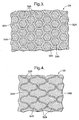
- the second layer may comprise a hexagonal current collector mesh in a metal and ceramic cermet.
- the second layer may comprise a sinusoidal current collector mesh in a metal and ceramic cermet.
- the second layer may comprise a plurality of discontinuous current collector members in a metal and ceramic cermet.
- the nickel and ceramic cermet may comprise nickel and yttria stabilised zirconia cermet, nickel and ceria cermet or nickel and perovskite cermet.
- the anode electrode may comprise a fourth layer arranged on the third layer and a fifth layer arranged on the fourth layer, the fourth layer comprising a current collector embedded in a metal and ceramic cermet and the fifth layer comprising a metal and ceramic cermet.
- the anode electrode may comprise a sixth layer arranged on the fifth layer and a seventh layer arranged on the sixth layer, the sixth layer comprising a current collector embedded in a metal and ceramic cermet and the seventh layer comprising a metal and ceramic cermet.
- a solid oxide fuel cell module 10 according to the present invention is shown in figure 1 and comprises a hollow support member 12 and a plurality of solid oxide fuel cells 16 spaced apart longitudinally on at least one flat surface 14 of the hollow support member 12.
- the hollow support member 12 has one or more passages 13 extending longitudinally therethrough for the supply of one of the reactants, for example fuel e.g. hydrogen.
- Each solid oxide fuel cell 16 comprises an anode electrode 18, an electrolyte 20 and a cathode electrode 22.
- a plurality of interconnectors 24 are arranged to electrically connect the solid oxide fuel cells 16 in electrical series. Each interconnector 24 electrically connects an anode electrode 18 of one solid oxide fuel cell 16 to a cathode electrode 22 of an adjacent solid oxide fuel cell 16.
- each solid oxide fuel cell 16 is arranged on the hollow support member 12, in the example where the fuel is supplied through the at least one passage 13 in the hollow support member 12.
- the electrolyte 20 of each solid oxide fuel cell 16 is arranged on the respective anode electrode 18 and the cathode electrode 22 of each solid oxide fuel cell 16 is arranged on the respective electrolyte 20.
- the anode electrode 18 of each solid oxide fuel cell 16 comprises a first layer 26 adjacent the electrolyte 20, a second layer 28 on the first layer 26 and a third layer 30 on the second layer 28, as shown in figure 2 .
- the first layer 26 comprises a nickel and ceramic cermet
- the second layer 28 comprises a current collector 32 embedded in a nickel and ceramic cermet 34
- the third layer 30 comprises a nickel and ceramic cermet.
- the current collector 32 may comprise nickel.
- the current collector 32 may comprise a nickel and ceramic cermet, the nickel and ceramic cermet of the current collector 32 having a higher concentration of nickel than the concentration of nickel in the nickel and ceramic cermet 34 of the first layer 26, second layer 28 and third layer 30.
- the current collector 32 may comprise a nickel and ceramic cermet, the nickel and ceramic cermet of the current collector 32 having different sized nickel and ceramic particles than the sizes of the nickel and ceramic particles of the nickel and ceramic cermet of the first layer 26, second layer 28 and third layer 30.
- the current collector 32 may comprise nickel and ceramic cermet, the nickel and ceramic cermet of the current collector 32 having less porosity than the nickel and ceramic cermet of the first layer 26, second layer 28 and third layer 30.
- the current collector 32 may comprise nickel and ceramic cermet, the nickel and ceramic cermet of the current collector 32 having different shaped and/or sized nickel and ceramic particles than the shapes and/or sizes of the nickel and ceramic particles of the nickel and ceramic cermet of the first layer 26, second layer 28 and third layer 30.
- the current collector 32 may comprise nickel and ceramic cermet, the nickel and ceramic cermet of the current collector 32 containing less pore formers than the nickel and ceramic cermet of the first layer 26, second layer 28 and third layer 30.
- the second layer 28 may comprise a current collector mesh 32 embedded in a nickel and ceramic cermet 34 such that the length of the current collector mesh 32 is not continuous in any one direction.
- the second layer 28 preferably comprises a hexagonal current collector mesh 32A in a nickel and ceramic cermet 34A as shown in figure 3 .
- the second layer 28 comprises a sinusoidal current collector mesh 32B in a nickel and ceramic cermet 34B, as shown in figure 4 .
- the second layer 28 comprises a plurality of discontinuous current collector members 32C in a nickel and ceramic cermet 34C, as shown in figure 5 .
- the arrangement is such as to minimise stresses in the anode electrode 18, while maximising in plane electrical conduction.
- the layers of the solid oxide fuel cells are preferably deposited by screen-printing, inkjet printing or transfer printing directly on the other layers.
- the layers of the solid oxide fuel cells may be deposited by radio frequency sputtering, thermal spraying or plasma spraying, but with the use of masks to limit the deposition to the areas required on the other layers.
- the nickel and ceramic cermet comprises nickel and yttria stabilised zirconia (YSZ) cermet or alternatively the nickel and ceramic cermet comprises nickel and ceria cermet or nickel and perovskite cermet.
- YSZ yttria stabilised zirconia
- the present invention provides a composite anode electrode with tailored microstructure to enhance in plane electrical conductance.
- the enhanced in plane electrical conductance is achieved by providing a current collector, (e.g. connected regions of the composite anode electrode with enhanced current collection capability) having more nickel and/or having less porosity, encapsulated in regions optimised for electrochemical reactions, having lots of reaction sites and a porous structure.
- the present invention allows materials to be used in the current collector of the composite anode electrode, which have a coefficient of thermal expansion (CTE) that is mismatched with respect to that of the electrolyte or which generate a volume change during oxidation or reduction.
- CTE coefficient of thermal expansion
- the re-oxidation cycling stability of the composite anode electrode is enhanced. This is achieved by arranging the current collector in patterns/shapes such that it is not continuous in any one direction, hence reducing stresses.
- the present invention allows materials to be used in the current collector of the composite anode electrode, which do not adhere/bond well to other solid oxide fuel cell materials. This is achieved by encapsulating the current collector within the anode electrode, so that only the anode electrode is in direct contact with the current collector and the adjacent layers and materials of the solid oxide fuel cells.
- the present invention provides a composite anode electrode microstructure, which has an enhanced thermal stability. Over time at high temperatures small nickel particles tend to coarsen, which alters the microstructure of the anode electrode so that there are less percolations of the nickel particles and hence this leads to a decrease in the in plane electrical conductivity in a conventional anode electrode.
- the current collector of the composite anode electrode has a denser nickel microstructure than a conventional anode electrode and hence the nickel particles will coarsen at a slower rate than the small nickel particles in the anode electrode and this leads to a slower decrease in the in plane electrical conductivity of the whole composite anode electrode over time.
- the first, second and third layers of the anode electrode may comprise other suitable metal and ceramic cermets, for example copper, palladium, platinum, rhenium or rhodium combined with yttria stabilised zirconia (YSZ), ceria or perovskite.
- the first, second and third layers of the anode electrode may comprise other suitable metal and ceramic cermets for example mixtures of two or more of copper, nickel, palladium, platinum, rhenium or rhodium combined with yttria stabilised zirconia (YSZ), ceria or perovskite.
- the current collector may comprise other suitable metals, for example copper, palladium, platinum, rhenium or rhodium or alloys of copper, nickel, palladium, platinum, rhenium and rhodium.
- the current collector may comprise other metal and ceramic cermets for example copper, palladium, platinum, rhenium or rhodium combined with yttria stabilised zirconia (YSZ), ceria or perovskite again with a higher concentration of metal in the current collector than in the first, second and third layers of the anode electrode.
- YSZ yttria stabilised zirconia
- the current collector may comprise other suitable metals, for example copper, palladium, platinum, rhenium or rhodium or alloys of copper, nickel, palladium, platinum, rhenium and rhodium.
- the current collector may comprise other metal and ceramic cermets for example copper, palladium, platinum, rhenium or rhodium combined with yttria stabilised zirconia (YSZ), ceria or perovskite again with different sized metal and ceramic particles in the metal and ceramic of the current collector than the sizes of the metal and ceramic particles in the first, second and third layers of the anode electrode.
- YSZ yttria stabilised zirconia
- the current collector may comprise other suitable metals, for example copper, palladium, platinum, rhenium or rhodium or alloys of copper, nickel, palladium, platinum, rhenium and rhodium.
- the current collector may comprise other metal and ceramic cermets for example copper, palladium, platinum, rhenium or rhodium combined with yttria stabilised zirconia (YSZ), ceria or perovskite again with less porosity in the metal and ceramic of the current collector than in the metal and ceramic of the first, second and third layers of the anode electrode.
- the metal and ceramic particles of the current collector may again have different sized and/or shaped particles metal and ceramic particles or less pore formers than the metal and ceramic particles of the first, second and third layers.
- anode electrode with a single current collector in the second layer of a three-layer anode electrode it is equally possible to provide an anode electrode with other suitable numbers of current collectors and layers. For example two current collectors in the second and fourth layers of a five- layer anode electrode or three current collectors in the second, fourth and sixth layers of a seven-layer anode electrode, etc.
- the current collector it is possible to arrange for the current collector to have a variation in the diameter, or cross-sectional area, of the holes in the hexagonal mesh of the current collector such that conduction perpendicular to the layers is different at different positions, for example to vary the conduction from one side to the other side of the anode electrode. It is possible to arrange for the current collector to have a variation in the diameter, or cross-sectional area, of the holes in the sinusoidal mesh of the current collector such that conduction perpendicular to the layers is different at different positions, for example to vary the conduction from one side to the other side of the anode electrode.
Landscapes
- Chemical & Material Sciences (AREA)
- Chemical Kinetics & Catalysis (AREA)
- Electrochemistry (AREA)
- General Chemical & Material Sciences (AREA)
- Engineering & Computer Science (AREA)
- Life Sciences & Earth Sciences (AREA)
- Sustainable Energy (AREA)
- Sustainable Development (AREA)
- Manufacturing & Machinery (AREA)
- Health & Medical Sciences (AREA)
- Composite Materials (AREA)
- Materials Engineering (AREA)
- Ceramic Engineering (AREA)
- Anesthesiology (AREA)
- Heart & Thoracic Surgery (AREA)
- Hematology (AREA)
- Biomedical Technology (AREA)
- Animal Behavior & Ethology (AREA)
- General Health & Medical Sciences (AREA)
- Public Health (AREA)
- Veterinary Medicine (AREA)
- Pulmonology (AREA)
- Bioinformatics & Cheminformatics (AREA)
- Otolaryngology (AREA)
- Inert Electrodes (AREA)
- Fuel Cell (AREA)
Claims (15)
- Festoxid-Brennstoffzellenmodul (10), das eine Mehrzahl von Festoxid-Brennstoffzellen (16) umfasst, wobei jede Brennstoffzelle (16) eine Anodenelektrode (18), einen Elektrolyt (20) und eine Kathodenelektrode (22) umfasst, wobei eine Mehrzahl von Zwischenverbindungsgliedem (24) so angeordnet ist, dass sie die Brennstoffzellen (16) in elektrischer Reihe elektrisch verbinden, wobei jedes Zwischenverbindungsglied (24) eine Anodenelektrode (18) einer Brennstoffzelle (16) mit einer Kathodenelektrode (22) einer benachbarten Brennstoffzelle (16) elektrisch verbindet, wobei die Anodenelektrode (18) mindestens drei Schichten (26, 28, 30) umfasst, wobei eine erste Schicht (26) auf dem Elektrolyt (20) angeordnet ist, wobei eine zweite Schicht (28) auf der ersten Schicht (26) angeordnet ist, und wobei eine dritte Schicht (30) auf der zweiten Schicht (28) angeordnet ist, wobei die erste Schicht (26) einen Keramik-Metall-Verbundwerkstoff, Cermet, umfasst, wobei die dritte Schicht (30) einen Keramik-Metall-Verbundwerkstoff, Cermet, umfasst, dadurch gekennzeichnet, dass die zweite Schicht (28) einen Stromabnehmer (32) und einen Keramik-Metall-Verbundwerkstoff, Cermet, (34) umfasst, wobei der Stromabnehmer (32) in den Keramik-Metall-Verbundwerkstoff, Cermet, (34) der zweiten Schicht eingebettet ist, wobei der Stromabnehmer (32) einen Keramik-Metall-Verbundwerkstoff, Cermet, umfasst; wobei der Keramik-Metall-Verbundwerkstoff, Cermet, des Stromabnehmers (32) eine höhere Metallkonzentration als die Metallkonzentration in dem Keramik-Metall-Verbundwerkstoff, Cermet, der ersten Schicht (26), der zweiten Schicht (28) und der dritten Schicht (30) aufweist, oder wobei der Keramik-Metall-Verbundwerkstoff des Stromabnehmers (32) Keramik- und Metallpartikel anderer Größe als die Keramik- und Metallpartikel des Keramik-Metall-Verbundwerkstoffs, Cermet, der ersten Schicht (26), der zweiten Schicht (28) und der dritten Schicht (30) aufweist, oder wobei der Keramik-Metall-Verbundwerkstoff, Cermet, des Stromabnehmers (32) eine geringere Porosität aufweist als der Keramik-Metall-Verbundwerkstoff der ersten Schicht (26), der zweiten Schicht (28) und der dritten Schicht (30).
- Festoxid-Brennstoffzellenmodul nach Anspruch 1, wobei das Metall des Keramik-Metall-Verbundwerkstoffs, Cermet, mindestens eines der folgenden Metalle umfasst: Kupfer, Nickel, Palladium, Platin, Rhenium oder Rhodium.
- Festoxid-Brennstoffzellenmodul nach Anspruch 1 oder Anspruch 2, wobei der Keramikwerkstoff des Keramik-Metall-Verbundwerkstoffs, Cermet, mindestens eines der folgenden umfasst: Yttriumoxid, stabilisiertes Zirconiumoxid, Cerdioxid oder Perowskit.
- Festoxid-Brennstoffzellenmodul nach Anspruch 1, wobei der Keramik-Metall-Verbundwerkstoff, Cermet, des Stromabnehmers (32) Keramik- und Metallpartikel in anderer Form und/oder anderer Größe als die Formen und/oder Größen der Keramik- und Metallpartikel des Keramik-Metall-Verbundwerkstoffs der ersten Schicht (26), der zweiten Schicht (28) und der dritten Schicht (30) aufweist.
- Festoxid-Brennstoffzellenmodul nach Anspruch 1, wobei der Keramik-Metall-Verbundwerkstoff, Cermet, des Stromabnehmers (32) weniger Porenbilder aufweist als der Keramik-Metall-Verbundwerkstoff, Cermet, der ersten Schicht (26), der zweiten Schicht (28) und der dritten Schicht (30).
- Festoxid-Brennstoffzellernnodul nach einem der Ansprüche 1 bis 3, wobei die erste Schicht (26) ein Nicke-Keramik-Cermet umfasst, wobei die zweite Schicht (28) einen Stromabnehmer (32) umfasst, der in ein Nicke-Keramik-Cermet eingebettet ist, und wobei die dritte Schicht (30) ein Nickel-Keramik-Cermet umfasst.
- Festoxid-Brennstoffzellenmodul nach Anspruch 6, wobei der Stromabnehmer (32) ein Nickel-Keramik-Cermet umfasst, wobei das Nickel-Keramik-Cermet des Stromabnehmers (32) eine höhere Nickelkonzentration aufweist als die Nickelkonzentration in dem Nickel-Keramik-Cermet der ersten Schicht (26), der zweiten Schicht (28) und der dritten Schicht (30).
- Festoxid-Brennstoffzellenmodul nach Anspruch 6, wobei der Stromabnehmer (32) ein Nickel-Keramik-Cermet umfasst, wobei das Nickel-Keramik-Cermet des Stromabnehmers (32) Nickel- und Keramikpartikel in anderen Größen als die Nickel- und Keramikpartikel des Nickel-Keramik-Cermet der ersten Schicht (26), der zweiten Schicht (28) und der dritten Schicht (30) aufweist.
- Festoxid-Brennstoffzellenmodul nach Anspruch 6, wobei der Stromabnehmer (32) ein Nickel-Keramik-Cermet umfasst, wobei das Nickel-Keramik-Cermet des Stromabnehmers (32) eine geringere Porosität aufweist als die Porosität des Nickel-Keramik-Cermet der ersten Schicht (26), der zweiten Schicht (28) und der dritten Schicht (30).
- Festoxid-Brennstoffzellenmodul nach Anspruch 9, wobei der Stromabnehmer (32) ein Nickel-Keramik-Cermet umfasst, wobei das Nickel-Keramik-Cermet des Stromabnehmers (32) Nickel- und Keramikpartikel in anderer Form und/oder in anderer Größe aufweist als die Nickel- und Keramikpartikel des Nickel-Keramik-Cermet der ersten Schicht (26), der zweiten Schicht (28) und der dritten Schicht (30).
- Festoxid-Brennstoffzellenmodul nach Anspruch 9, wobei der Stromabnehmer (32) ein Nickel-Keramik-Cermet umfasst, wobei das Nickel-Keramik-Cermet des Stromabnehmers (32) weniger Porenformer aufweist als das Nickel-Keramik-Cermet der ersten Schicht (26), der zweiten Schicht (28) und der dritten Schicht (30).
- Festoxid-Brennstoffzellenmodul nach einem der Ansprüche 1 bis 11, wobei der Stromabnehmer (32) ein Nickel-Keramik-Cermet umfasst, wobei die zweite Schicht (28) ein Stromabnehmernetz (32A, 32B) umfasst, das in einen Keramik-Metall-Verbundwerkstoff, Cermet, eingebettet ist.
- Festoxid-Brennstoffzellenmodul nach Anspruch 12, wobei die zweite Schicht (28) ein hexagonales Stromabnehmernetz (32A) in einem Keramik-Metall-Verbundwerkstoff, Cermet, umfasst.
- Festoxid-Brennstoffzellernnodul nach Anspruch 12, wobei die zweite Schicht (28) ein sinuskurvenförmiges Stromabnehmernetz (32A) in einem Keramik-Metall-Verbundwerkstoff, Cermet, umfasst.
- Feststoff-Brennstoffzellenmodul nach einem der Ansprüche 1 bis 11, wobei die zweite Schicht (28) eine Mehrzahl unterbrochener Stromabnehmerelemente (32C) in einem Keramik-Metall-Verbundwerkstoff, Cermet, umfasst.
Applications Claiming Priority (2)
| Application Number | Priority Date | Filing Date | Title |
|---|---|---|---|
| GBGB0602842.7A GB0602842D0 (en) | 2006-02-14 | 2006-02-14 | A Solid Oxide Fuel Cell And A Solid Oxide Fuel Cell Module |
| PCT/GB2007/000182 WO2007093759A1 (en) | 2006-02-14 | 2007-01-23 | A solid oxide fuel cell module with multilayered anode |
Publications (2)
| Publication Number | Publication Date |
|---|---|
| EP2044641A1 EP2044641A1 (de) | 2009-04-08 |
| EP2044641B1 true EP2044641B1 (de) | 2013-12-25 |
Family
ID=36119962
Family Applications (1)
| Application Number | Title | Priority Date | Filing Date |
|---|---|---|---|
| EP07704961.7A Not-in-force EP2044641B1 (de) | 2006-02-14 | 2007-01-23 | Festoxid-brennstoffzellenmodul mit mehrschichtiger anode |
Country Status (5)
| Country | Link |
|---|---|
| EP (1) | EP2044641B1 (de) |
| DK (1) | DK2044641T3 (de) |
| ES (1) | ES2441592T3 (de) |
| GB (1) | GB0602842D0 (de) |
| WO (1) | WO2007093759A1 (de) |
Families Citing this family (7)
| Publication number | Priority date | Publication date | Assignee | Title |
|---|---|---|---|---|
| US8828618B2 (en) * | 2007-12-07 | 2014-09-09 | Nextech Materials, Ltd. | High performance multilayer electrodes for use in reducing gases |
| JP5418975B2 (ja) | 2008-10-16 | 2014-02-19 | Toto株式会社 | 固体酸化物形燃料電池セル、及びそれを備える燃料電池モジュール |
| US8883368B2 (en) | 2008-11-21 | 2014-11-11 | Ballard Power Systems Inc. | Solid oxide fuel cell having rigidized support including nickel-based alloy |
| KR101741849B1 (ko) | 2008-12-08 | 2017-05-30 | 넥스테크 머티리얼스, 엘티디. | 고체 산화물 연료 전지 스택용 집전 장치 |
| EP2333883A1 (de) | 2009-11-18 | 2011-06-15 | Forschungszentrum Jülich Gmbh (FJZ) | Anode für eine Hochtemperatur-Brennstoffzelle sowie deren Herstellung |
| CN106654290B (zh) * | 2015-10-30 | 2019-06-25 | 中国科学院大连化学物理研究所 | 多级阶梯状孔结构水传输板及其制备 |
| DE102016122888A1 (de) * | 2016-11-28 | 2018-05-30 | Technische Universität Clausthal | Festoxidbrennstoffzelle, Brennstoffzellenstapel und Verfahren zur Herstellung einer Festoxidbrennstoffzelle |
Family Cites Families (9)
| Publication number | Priority date | Publication date | Assignee | Title |
|---|---|---|---|---|
| US5035962A (en) * | 1990-03-21 | 1991-07-30 | Westinghouse Electric Corp. | Layered method of electrode for solid oxide electrochemical cells |
| US5273837A (en) | 1992-12-23 | 1993-12-28 | Corning Incorporated | Solid electrolyte fuel cells |
| JPH07245107A (ja) | 1994-03-03 | 1995-09-19 | Fujikura Ltd | 固体電解質燃料電池 |
| AUPN876896A0 (en) * | 1996-03-18 | 1996-04-18 | Ceramic Fuel Cells Limited | An electrical interconnect for a planar fuel cell |
| AUPQ315499A0 (en) * | 1999-09-29 | 1999-10-21 | Ceramic Fuel Cells Limited | Fuel cell assembly |
| WO2001091218A2 (en) * | 2000-05-22 | 2001-11-29 | Acumentrics Corporation | Electrode-supported solid state electrochemical cell |
| GB0024106D0 (en) | 2000-10-03 | 2000-11-15 | Rolls Royce Plc | A solid oxide fuel cell stack and a method of manufacturing a solid oxide fuel cell stack |
| GB0217794D0 (en) * | 2002-08-01 | 2002-09-11 | Univ St Andrews | Fuel cell electrodes |
| US7781123B2 (en) * | 2005-06-06 | 2010-08-24 | Delphi Technologies, Inc. | Method and apparatus for forming electrode interconnect contacts for a solid-oxide fuel cell stack |
-
2006
- 2006-02-14 GB GBGB0602842.7A patent/GB0602842D0/en not_active Ceased
-
2007
- 2007-01-23 EP EP07704961.7A patent/EP2044641B1/de not_active Not-in-force
- 2007-01-23 DK DK07704961.7T patent/DK2044641T3/da active
- 2007-01-23 ES ES07704961.7T patent/ES2441592T3/es active Active
- 2007-01-23 WO PCT/GB2007/000182 patent/WO2007093759A1/en not_active Ceased
Also Published As
| Publication number | Publication date |
|---|---|
| GB0602842D0 (en) | 2006-03-22 |
| WO2007093759A1 (en) | 2007-08-23 |
| EP2044641A1 (de) | 2009-04-08 |
| DK2044641T3 (da) | 2014-01-27 |
| ES2441592T3 (es) | 2014-02-05 |
Similar Documents
| Publication | Publication Date | Title |
|---|---|---|
| EP1217676B1 (de) | Festoxidbrennstoffzelle mit einer Gasdiffusionsmatte und Festoxidbrennstoffzellenstapel mit einer derartigen Matte und einer Verbundleiterplatte | |
| CN100377404C (zh) | 固体电解质型燃料电池及其上使用的空气极集电体 | |
| EP1529318B1 (de) | Gasdurchlässiges substrat und seine verwendung in einer festoxid-brennstoffzelle | |
| AU784450B2 (en) | High performance ceramic fuel cell interconnect with integrated flowpaths and method for making same | |
| EP2044641B1 (de) | Festoxid-brennstoffzellenmodul mit mehrschichtiger anode | |
| EP3442064B1 (de) | Einheitszelle einer brennstoffzelle | |
| US20050136312A1 (en) | Compliant fuel cell system | |
| EP2043187B1 (de) | Festoxidbrennstoffzelle und Herstellungsverfahren dafür | |
| US20080107948A1 (en) | High Specific Power Solid Oxide Fuel Cell Stack | |
| US7651810B2 (en) | Interconnect supported fuel cell assembly, preform and method of fabrication | |
| JP2003115301A (ja) | 燃料電池用単セル及び固体電解質型燃料電池 | |
| AU2008277838B2 (en) | Cell materials variation in SOFC stacks to address thermal gradients in all planes | |
| JP4512911B2 (ja) | 固体電解質型燃料電池 | |
| EP1643013A1 (de) | Durch Bipolarplatten unterstützte Elektrolysevorrichtung, Vorform und Herstellungsverfahren | |
| US20070141435A1 (en) | Fuel cell with a brazed interconnect and method of assembling the same | |
| US20110269054A1 (en) | Fuel cell with a brazed interconnect and method of assembling the same | |
| JP7649810B2 (ja) | 電気化学セル | |
| EP1647323A2 (de) | Wärmeableitende metalische Lage für Ionenleiter mit mehreren Schichten | |
| JP2013026221A (ja) | ろう付けインターコネクトを有する燃料電池及びその組立方法 |
Legal Events
| Date | Code | Title | Description |
|---|---|---|---|
| PUAI | Public reference made under article 153(3) epc to a published international application that has entered the european phase |
Free format text: ORIGINAL CODE: 0009012 |
|
| 17P | Request for examination filed |
Effective date: 20081215 |
|
| AK | Designated contracting states |
Kind code of ref document: A1 Designated state(s): AT BE BG CH CY CZ DE DK EE ES FI FR GB GR HU IE IS IT LI LT LU LV MC NL PL PT RO SE SI SK TR |
|
| AX | Request for extension of the european patent |
Extension state: AL BA HR MK RS |
|
| 17Q | First examination report despatched |
Effective date: 20100825 |
|
| DAX | Request for extension of the european patent (deleted) | ||
| RAP1 | Party data changed (applicant data changed or rights of an application transferred) |
Owner name: LG FUEL CELL SYSTEMS, INC. |
|
| GRAP | Despatch of communication of intention to grant a patent |
Free format text: ORIGINAL CODE: EPIDOSNIGR1 |
|
| GRAS | Grant fee paid |
Free format text: ORIGINAL CODE: EPIDOSNIGR3 |
|
| GRAA | (expected) grant |
Free format text: ORIGINAL CODE: 0009210 |
|
| AK | Designated contracting states |
Kind code of ref document: B1 Designated state(s): AT BE BG CH CY CZ DE DK EE ES FI FR GB GR HU IE IS IT LI LT LU LV MC NL PL PT RO SE SI SK TR |
|
| REG | Reference to a national code |
Ref country code: GB Ref legal event code: FG4D |
|
| REG | Reference to a national code |
Ref country code: CH Ref legal event code: EP |
|
| REG | Reference to a national code |
Ref country code: AT Ref legal event code: REF Ref document number: 647013 Country of ref document: AT Kind code of ref document: T Effective date: 20140115 Ref country code: CH Ref legal event code: NV Representative=s name: MEYER AND KOLLEGEN, CH |
|
| REG | Reference to a national code |
Ref country code: DK Ref legal event code: T3 Effective date: 20140124 |
|
| REG | Reference to a national code |
Ref country code: NL Ref legal event code: T3 Ref country code: IE Ref legal event code: FG4D |
|
| REG | Reference to a national code |
Ref country code: ES Ref legal event code: FG2A Ref document number: 2441592 Country of ref document: ES Kind code of ref document: T3 Effective date: 20140205 |
|
| REG | Reference to a national code |
Ref country code: NL Ref legal event code: T3 |
|
| REG | Reference to a national code |
Ref country code: DE Ref legal event code: R096 Ref document number: 602007034420 Country of ref document: DE Effective date: 20140213 |
|
| PG25 | Lapsed in a contracting state [announced via postgrant information from national office to epo] |
Ref country code: LT Free format text: LAPSE BECAUSE OF FAILURE TO SUBMIT A TRANSLATION OF THE DESCRIPTION OR TO PAY THE FEE WITHIN THE PRESCRIBED TIME-LIMIT Effective date: 20131225 Ref country code: FI Free format text: LAPSE BECAUSE OF FAILURE TO SUBMIT A TRANSLATION OF THE DESCRIPTION OR TO PAY THE FEE WITHIN THE PRESCRIBED TIME-LIMIT Effective date: 20131225 Ref country code: SE Free format text: LAPSE BECAUSE OF FAILURE TO SUBMIT A TRANSLATION OF THE DESCRIPTION OR TO PAY THE FEE WITHIN THE PRESCRIBED TIME-LIMIT Effective date: 20131225 |
|
| REG | Reference to a national code |
Ref country code: AT Ref legal event code: MK05 Ref document number: 647013 Country of ref document: AT Kind code of ref document: T Effective date: 20131225 |
|
| REG | Reference to a national code |
Ref country code: LT Ref legal event code: MG4D |
|
| PG25 | Lapsed in a contracting state [announced via postgrant information from national office to epo] |
Ref country code: LV Free format text: LAPSE BECAUSE OF FAILURE TO SUBMIT A TRANSLATION OF THE DESCRIPTION OR TO PAY THE FEE WITHIN THE PRESCRIBED TIME-LIMIT Effective date: 20131225 |
|
| PG25 | Lapsed in a contracting state [announced via postgrant information from national office to epo] |
Ref country code: EE Free format text: LAPSE BECAUSE OF FAILURE TO SUBMIT A TRANSLATION OF THE DESCRIPTION OR TO PAY THE FEE WITHIN THE PRESCRIBED TIME-LIMIT Effective date: 20131225 Ref country code: IS Free format text: LAPSE BECAUSE OF FAILURE TO SUBMIT A TRANSLATION OF THE DESCRIPTION OR TO PAY THE FEE WITHIN THE PRESCRIBED TIME-LIMIT Effective date: 20140425 |
|
| PG25 | Lapsed in a contracting state [announced via postgrant information from national office to epo] |
Ref country code: SK Free format text: LAPSE BECAUSE OF FAILURE TO SUBMIT A TRANSLATION OF THE DESCRIPTION OR TO PAY THE FEE WITHIN THE PRESCRIBED TIME-LIMIT Effective date: 20131225 Ref country code: PT Free format text: LAPSE BECAUSE OF FAILURE TO SUBMIT A TRANSLATION OF THE DESCRIPTION OR TO PAY THE FEE WITHIN THE PRESCRIBED TIME-LIMIT Effective date: 20140428 Ref country code: CY Free format text: LAPSE BECAUSE OF FAILURE TO SUBMIT A TRANSLATION OF THE DESCRIPTION OR TO PAY THE FEE WITHIN THE PRESCRIBED TIME-LIMIT Effective date: 20131225 Ref country code: RO Free format text: LAPSE BECAUSE OF FAILURE TO SUBMIT A TRANSLATION OF THE DESCRIPTION OR TO PAY THE FEE WITHIN THE PRESCRIBED TIME-LIMIT Effective date: 20131225 Ref country code: PL Free format text: LAPSE BECAUSE OF FAILURE TO SUBMIT A TRANSLATION OF THE DESCRIPTION OR TO PAY THE FEE WITHIN THE PRESCRIBED TIME-LIMIT Effective date: 20131225 Ref country code: LU Free format text: LAPSE BECAUSE OF FAILURE TO SUBMIT A TRANSLATION OF THE DESCRIPTION OR TO PAY THE FEE WITHIN THE PRESCRIBED TIME-LIMIT Effective date: 20140123 Ref country code: AT Free format text: LAPSE BECAUSE OF FAILURE TO SUBMIT A TRANSLATION OF THE DESCRIPTION OR TO PAY THE FEE WITHIN THE PRESCRIBED TIME-LIMIT Effective date: 20131225 Ref country code: CZ Free format text: LAPSE BECAUSE OF FAILURE TO SUBMIT A TRANSLATION OF THE DESCRIPTION OR TO PAY THE FEE WITHIN THE PRESCRIBED TIME-LIMIT Effective date: 20131225 |
|
| REG | Reference to a national code |
Ref country code: DE Ref legal event code: R097 Ref document number: 602007034420 Country of ref document: DE |
|
| PG25 | Lapsed in a contracting state [announced via postgrant information from national office to epo] |
Ref country code: MC Free format text: LAPSE BECAUSE OF FAILURE TO SUBMIT A TRANSLATION OF THE DESCRIPTION OR TO PAY THE FEE WITHIN THE PRESCRIBED TIME-LIMIT Effective date: 20131225 |
|
| PLBE | No opposition filed within time limit |
Free format text: ORIGINAL CODE: 0009261 |
|
| STAA | Information on the status of an ep patent application or granted ep patent |
Free format text: STATUS: NO OPPOSITION FILED WITHIN TIME LIMIT |
|
| REG | Reference to a national code |
Ref country code: IE Ref legal event code: MM4A |
|
| 26N | No opposition filed |
Effective date: 20140926 |
|
| REG | Reference to a national code |
Ref country code: DE Ref legal event code: R097 Ref document number: 602007034420 Country of ref document: DE Effective date: 20140926 |
|
| PG25 | Lapsed in a contracting state [announced via postgrant information from national office to epo] |
Ref country code: IE Free format text: LAPSE BECAUSE OF NON-PAYMENT OF DUE FEES Effective date: 20140123 |
|
| PG25 | Lapsed in a contracting state [announced via postgrant information from national office to epo] |
Ref country code: SI Free format text: LAPSE BECAUSE OF FAILURE TO SUBMIT A TRANSLATION OF THE DESCRIPTION OR TO PAY THE FEE WITHIN THE PRESCRIBED TIME-LIMIT Effective date: 20131225 |
|
| REG | Reference to a national code |
Ref country code: FR Ref legal event code: PLFP Year of fee payment: 10 |
|
| PG25 | Lapsed in a contracting state [announced via postgrant information from national office to epo] |
Ref country code: BG Free format text: LAPSE BECAUSE OF FAILURE TO SUBMIT A TRANSLATION OF THE DESCRIPTION OR TO PAY THE FEE WITHIN THE PRESCRIBED TIME-LIMIT Effective date: 20131225 |
|
| PG25 | Lapsed in a contracting state [announced via postgrant information from national office to epo] |
Ref country code: GR Free format text: LAPSE BECAUSE OF FAILURE TO SUBMIT A TRANSLATION OF THE DESCRIPTION OR TO PAY THE FEE WITHIN THE PRESCRIBED TIME-LIMIT Effective date: 20140326 |
|
| PG25 | Lapsed in a contracting state [announced via postgrant information from national office to epo] |
Ref country code: HU Free format text: LAPSE BECAUSE OF FAILURE TO SUBMIT A TRANSLATION OF THE DESCRIPTION OR TO PAY THE FEE WITHIN THE PRESCRIBED TIME-LIMIT; INVALID AB INITIO Effective date: 20070123 |
|
| REG | Reference to a national code |
Ref country code: FR Ref legal event code: PLFP Year of fee payment: 11 |
|
| PGFP | Annual fee paid to national office [announced via postgrant information from national office to epo] |
Ref country code: NL Payment date: 20170119 Year of fee payment: 11 |
|
| PGFP | Annual fee paid to national office [announced via postgrant information from national office to epo] |
Ref country code: FR Payment date: 20170120 Year of fee payment: 11 Ref country code: DE Payment date: 20170120 Year of fee payment: 11 Ref country code: CH Payment date: 20170119 Year of fee payment: 11 |
|
| PGFP | Annual fee paid to national office [announced via postgrant information from national office to epo] |
Ref country code: DK Payment date: 20170119 Year of fee payment: 11 Ref country code: GB Payment date: 20170119 Year of fee payment: 11 Ref country code: BE Payment date: 20170119 Year of fee payment: 11 |
|
| PGFP | Annual fee paid to national office [announced via postgrant information from national office to epo] |
Ref country code: ES Payment date: 20170113 Year of fee payment: 11 Ref country code: IT Payment date: 20170124 Year of fee payment: 11 Ref country code: TR Payment date: 20170118 Year of fee payment: 11 |
|
| REG | Reference to a national code |
Ref country code: DE Ref legal event code: R119 Ref document number: 602007034420 Country of ref document: DE |
|
| REG | Reference to a national code |
Ref country code: DK Ref legal event code: EBP Effective date: 20180131 |
|
| REG | Reference to a national code |
Ref country code: CH Ref legal event code: PL |
|
| REG | Reference to a national code |
Ref country code: NL Ref legal event code: MM Effective date: 20180201 |
|
| GBPC | Gb: european patent ceased through non-payment of renewal fee |
Effective date: 20180123 |
|
| PG25 | Lapsed in a contracting state [announced via postgrant information from national office to epo] |
Ref country code: DE Free format text: LAPSE BECAUSE OF NON-PAYMENT OF DUE FEES Effective date: 20180801 Ref country code: FR Free format text: LAPSE BECAUSE OF NON-PAYMENT OF DUE FEES Effective date: 20180131 |
|
| REG | Reference to a national code |
Ref country code: FR Ref legal event code: ST Effective date: 20180928 |
|
| REG | Reference to a national code |
Ref country code: BE Ref legal event code: MM Effective date: 20180131 |
|
| PG25 | Lapsed in a contracting state [announced via postgrant information from national office to epo] |
Ref country code: CH Free format text: LAPSE BECAUSE OF NON-PAYMENT OF DUE FEES Effective date: 20180131 Ref country code: BE Free format text: LAPSE BECAUSE OF NON-PAYMENT OF DUE FEES Effective date: 20180131 Ref country code: LI Free format text: LAPSE BECAUSE OF NON-PAYMENT OF DUE FEES Effective date: 20180131 Ref country code: GB Free format text: LAPSE BECAUSE OF NON-PAYMENT OF DUE FEES Effective date: 20180123 Ref country code: NL Free format text: LAPSE BECAUSE OF NON-PAYMENT OF DUE FEES Effective date: 20180201 |
|
| PG25 | Lapsed in a contracting state [announced via postgrant information from national office to epo] |
Ref country code: DK Free format text: LAPSE BECAUSE OF NON-PAYMENT OF DUE FEES Effective date: 20180131 |
|
| PG25 | Lapsed in a contracting state [announced via postgrant information from national office to epo] |
Ref country code: IT Free format text: LAPSE BECAUSE OF NON-PAYMENT OF DUE FEES Effective date: 20180123 |
|
| REG | Reference to a national code |
Ref country code: ES Ref legal event code: FD2A Effective date: 20190731 |
|
| PG25 | Lapsed in a contracting state [announced via postgrant information from national office to epo] |
Ref country code: ES Free format text: LAPSE BECAUSE OF NON-PAYMENT OF DUE FEES Effective date: 20180124 |
|
| PG25 | Lapsed in a contracting state [announced via postgrant information from national office to epo] |
Ref country code: TR Free format text: LAPSE BECAUSE OF NON-PAYMENT OF DUE FEES Effective date: 20180123 |