EP1647323A2 - Wärmeableitende metalische Lage für Ionenleiter mit mehreren Schichten - Google Patents
Wärmeableitende metalische Lage für Ionenleiter mit mehreren Schichten Download PDFInfo
- Publication number
- EP1647323A2 EP1647323A2 EP05022212A EP05022212A EP1647323A2 EP 1647323 A2 EP1647323 A2 EP 1647323A2 EP 05022212 A EP05022212 A EP 05022212A EP 05022212 A EP05022212 A EP 05022212A EP 1647323 A2 EP1647323 A2 EP 1647323A2
- Authority
- EP
- European Patent Office
- Prior art keywords
- interconnect
- outer edge
- cathode
- anode
- solid electrolyte
- Prior art date
- Legal status (The legal status is an assumption and is not a legal conclusion. Google has not performed a legal analysis and makes no representation as to the accuracy of the status listed.)
- Ceased
Links
- 229910052751 metal Inorganic materials 0.000 title claims description 23
- 239000002184 metal Substances 0.000 title claims description 23
- 239000010416 ion conductor Substances 0.000 title 1
- BQCADISMDOOEFD-UHFFFAOYSA-N Silver Chemical compound [Ag] BQCADISMDOOEFD-UHFFFAOYSA-N 0.000 claims abstract description 32
- 229910052709 silver Inorganic materials 0.000 claims abstract description 31
- 239000004332 silver Substances 0.000 claims abstract description 31
- BASFCYQUMIYNBI-UHFFFAOYSA-N platinum Chemical compound [Pt] BASFCYQUMIYNBI-UHFFFAOYSA-N 0.000 claims abstract description 26
- KDLHZDBZIXYQEI-UHFFFAOYSA-N Palladium Chemical compound [Pd] KDLHZDBZIXYQEI-UHFFFAOYSA-N 0.000 claims abstract description 24
- 229910052697 platinum Inorganic materials 0.000 claims abstract description 13
- PCHJSUWPFVWCPO-UHFFFAOYSA-N gold Chemical compound [Au] PCHJSUWPFVWCPO-UHFFFAOYSA-N 0.000 claims abstract description 12
- 229910052737 gold Inorganic materials 0.000 claims abstract description 12
- 239000010931 gold Substances 0.000 claims abstract description 12
- 229910052763 palladium Inorganic materials 0.000 claims abstract description 12
- 229910052703 rhodium Inorganic materials 0.000 claims abstract description 12
- 239000010948 rhodium Substances 0.000 claims abstract description 12
- MHOVAHRLVXNVSD-UHFFFAOYSA-N rhodium atom Chemical compound [Rh] MHOVAHRLVXNVSD-UHFFFAOYSA-N 0.000 claims abstract description 12
- 239000007784 solid electrolyte Substances 0.000 claims description 40
- 239000000203 mixture Substances 0.000 claims description 14
- 230000002093 peripheral effect Effects 0.000 claims description 13
- 239000001301 oxygen Substances 0.000 abstract description 24
- 229910052760 oxygen Inorganic materials 0.000 abstract description 24
- QVGXLLKOCUKJST-UHFFFAOYSA-N atomic oxygen Chemical compound [O] QVGXLLKOCUKJST-UHFFFAOYSA-N 0.000 abstract description 21
- 238000004519 manufacturing process Methods 0.000 abstract description 6
- 230000008646 thermal stress Effects 0.000 abstract description 6
- 239000003792 electrolyte Substances 0.000 description 26
- 239000007789 gas Substances 0.000 description 21
- 239000000463 material Substances 0.000 description 21
- 239000012528 membrane Substances 0.000 description 11
- 239000000047 product Substances 0.000 description 11
- 238000000034 method Methods 0.000 description 8
- 239000004020 conductor Substances 0.000 description 7
- KFZMGEQAYNKOFK-UHFFFAOYSA-N Isopropanol Chemical compound CC(C)O KFZMGEQAYNKOFK-UHFFFAOYSA-N 0.000 description 6
- 239000000919 ceramic Substances 0.000 description 6
- 239000000976 ink Substances 0.000 description 6
- 238000000576 coating method Methods 0.000 description 5
- 238000004891 communication Methods 0.000 description 5
- 229910044991 metal oxide Inorganic materials 0.000 description 5
- 230000008901 benefit Effects 0.000 description 4
- 239000011248 coating agent Substances 0.000 description 4
- 238000005245 sintering Methods 0.000 description 4
- 239000007921 spray Substances 0.000 description 4
- 238000005507 spraying Methods 0.000 description 4
- 230000007423 decrease Effects 0.000 description 3
- 230000000694 effects Effects 0.000 description 3
- -1 oxygen ions Chemical class 0.000 description 3
- 229910000502 Li-aluminosilicate Inorganic materials 0.000 description 2
- FVROQKXVYSIMQV-UHFFFAOYSA-N [Sr+2].[La+3].[O-][Mn]([O-])=O Chemical compound [Sr+2].[La+3].[O-][Mn]([O-])=O FVROQKXVYSIMQV-UHFFFAOYSA-N 0.000 description 2
- 239000000853 adhesive Substances 0.000 description 2
- 230000001070 adhesive effect Effects 0.000 description 2
- 229910045601 alloy Inorganic materials 0.000 description 2
- 239000000956 alloy Substances 0.000 description 2
- WUOACPNHFRMFPN-UHFFFAOYSA-N alpha-terpineol Chemical compound CC1=CCC(C(C)(C)O)CC1 WUOACPNHFRMFPN-UHFFFAOYSA-N 0.000 description 2
- 230000001680 brushing effect Effects 0.000 description 2
- 239000002131 composite material Substances 0.000 description 2
- SQIFACVGCPWBQZ-UHFFFAOYSA-N delta-terpineol Natural products CC(C)(O)C1CCC(=C)CC1 SQIFACVGCPWBQZ-UHFFFAOYSA-N 0.000 description 2
- 230000000994 depressogenic effect Effects 0.000 description 2
- 238000001704 evaporation Methods 0.000 description 2
- 239000011888 foil Substances 0.000 description 2
- 239000002241 glass-ceramic Substances 0.000 description 2
- 230000003993 interaction Effects 0.000 description 2
- 150000002500 ions Chemical class 0.000 description 2
- 229910002075 lanthanum strontium manganite Inorganic materials 0.000 description 2
- 150000004706 metal oxides Chemical class 0.000 description 2
- 238000002156 mixing Methods 0.000 description 2
- 230000003647 oxidation Effects 0.000 description 2
- 238000007254 oxidation reaction Methods 0.000 description 2
- 238000010422 painting Methods 0.000 description 2
- 238000000926 separation method Methods 0.000 description 2
- 239000002002 slurry Substances 0.000 description 2
- 239000002904 solvent Substances 0.000 description 2
- 239000000126 substance Substances 0.000 description 2
- 229940116411 terpineol Drugs 0.000 description 2
- WRIDQFICGBMAFQ-UHFFFAOYSA-N (E)-8-Octadecenoic acid Natural products CCCCCCCCCC=CCCCCCCC(O)=O WRIDQFICGBMAFQ-UHFFFAOYSA-N 0.000 description 1
- LQJBNNIYVWPHFW-UHFFFAOYSA-N 20:1omega9c fatty acid Natural products CCCCCCCCCCC=CCCCCCCCC(O)=O LQJBNNIYVWPHFW-UHFFFAOYSA-N 0.000 description 1
- QSBYPNXLFMSGKH-UHFFFAOYSA-N 9-Heptadecensaeure Natural products CCCCCCCC=CCCCCCCCC(O)=O QSBYPNXLFMSGKH-UHFFFAOYSA-N 0.000 description 1
- 229910001316 Ag alloy Inorganic materials 0.000 description 1
- MYMOFIZGZYHOMD-UHFFFAOYSA-N Dioxygen Chemical compound O=O MYMOFIZGZYHOMD-UHFFFAOYSA-N 0.000 description 1
- ZQPPMHVWECSIRJ-UHFFFAOYSA-N Oleic acid Natural products CCCCCCCCC=CCCCCCCCC(O)=O ZQPPMHVWECSIRJ-UHFFFAOYSA-N 0.000 description 1
- 239000005642 Oleic acid Substances 0.000 description 1
- XIVRETJQLTUPPZ-UHFFFAOYSA-N [Ca+2].[La+3].[O-][Cr]([O-])=O Chemical compound [Ca+2].[La+3].[O-][Cr]([O-])=O XIVRETJQLTUPPZ-UHFFFAOYSA-N 0.000 description 1
- ZJIYREZBRPWMMC-UHFFFAOYSA-N [Sr+2].[La+3].[O-][Cr]([O-])=O Chemical compound [Sr+2].[La+3].[O-][Cr]([O-])=O ZJIYREZBRPWMMC-UHFFFAOYSA-N 0.000 description 1
- 230000002411 adverse Effects 0.000 description 1
- 230000004888 barrier function Effects 0.000 description 1
- 230000009286 beneficial effect Effects 0.000 description 1
- 230000015572 biosynthetic process Effects 0.000 description 1
- ZFARUSOUMSKJOE-UHFFFAOYSA-N calcium dioxido(oxo)manganese lanthanum(3+) Chemical compound [Mn](=O)([O-])[O-].[Ca+2].[La+3] ZFARUSOUMSKJOE-UHFFFAOYSA-N 0.000 description 1
- 229910010293 ceramic material Inorganic materials 0.000 description 1
- 238000006243 chemical reaction Methods 0.000 description 1
- 238000002425 crystallisation Methods 0.000 description 1
- 230000008025 crystallization Effects 0.000 description 1
- QGBSISYHAICWAH-UHFFFAOYSA-N dicyandiamide Chemical compound NC(N)=NC#N QGBSISYHAICWAH-UHFFFAOYSA-N 0.000 description 1
- 238000009792 diffusion process Methods 0.000 description 1
- 229910001882 dioxygen Inorganic materials 0.000 description 1
- 239000000835 fiber Substances 0.000 description 1
- 238000010304 firing Methods 0.000 description 1
- 230000004907 flux Effects 0.000 description 1
- 239000011521 glass Substances 0.000 description 1
- 230000017525 heat dissipation Effects 0.000 description 1
- 238000010438 heat treatment Methods 0.000 description 1
- QXJSBBXBKPUZAA-UHFFFAOYSA-N isooleic acid Natural products CCCCCCCC=CCCCCCCCCC(O)=O QXJSBBXBKPUZAA-UHFFFAOYSA-N 0.000 description 1
- 238000002844 melting Methods 0.000 description 1
- 230000008018 melting Effects 0.000 description 1
- 229910001092 metal group alloy Inorganic materials 0.000 description 1
- 150000002739 metals Chemical class 0.000 description 1
- 229910000510 noble metal Inorganic materials 0.000 description 1
- ZQPPMHVWECSIRJ-KTKRTIGZSA-N oleic acid Chemical compound CCCCCCCC\C=C/CCCCCCCC(O)=O ZQPPMHVWECSIRJ-KTKRTIGZSA-N 0.000 description 1
- 239000002245 particle Substances 0.000 description 1
- 230000037361 pathway Effects 0.000 description 1
- 239000012466 permeate Substances 0.000 description 1
- 239000011148 porous material Substances 0.000 description 1
- 238000011084 recovery Methods 0.000 description 1
- 239000011347 resin Substances 0.000 description 1
- 229920005989 resin Polymers 0.000 description 1
- 238000007650 screen-printing Methods 0.000 description 1
- 239000007787 solid Substances 0.000 description 1
- 238000004901 spalling Methods 0.000 description 1
- 238000004544 sputter deposition Methods 0.000 description 1
- 230000035882 stress Effects 0.000 description 1
Images



Classifications
-
- B—PERFORMING OPERATIONS; TRANSPORTING
- B01—PHYSICAL OR CHEMICAL PROCESSES OR APPARATUS IN GENERAL
- B01D—SEPARATION
- B01D53/00—Separation of gases or vapours; Recovering vapours of volatile solvents from gases; Chemical or biological purification of waste gases, e.g. engine exhaust gases, smoke, fumes, flue gases, aerosols
- B01D53/32—Separation of gases or vapours; Recovering vapours of volatile solvents from gases; Chemical or biological purification of waste gases, e.g. engine exhaust gases, smoke, fumes, flue gases, aerosols by electrical effects other than those provided for in group B01D61/00
- B01D53/326—Separation of gases or vapours; Recovering vapours of volatile solvents from gases; Chemical or biological purification of waste gases, e.g. engine exhaust gases, smoke, fumes, flue gases, aerosols by electrical effects other than those provided for in group B01D61/00 in electrochemical cells
-
- C—CHEMISTRY; METALLURGY
- C01—INORGANIC CHEMISTRY
- C01B—NON-METALLIC ELEMENTS; COMPOUNDS THEREOF; METALLOIDS OR COMPOUNDS THEREOF NOT COVERED BY SUBCLASS C01C
- C01B13/00—Oxygen; Ozone; Oxides or hydroxides in general
- C01B13/02—Preparation of oxygen
- C01B13/0229—Purification or separation processes
- C01B13/0248—Physical processing only
- C01B13/0251—Physical processing only by making use of membranes
Definitions
- the present invention relates to an electrochemical device for the recovery of oxygen from an oxygen-containing gas, and in particular to an improved interconnect and stack design for reducing thermal gradients.
- SEOS solid electrolyte oxygen separation
- Each electrochemical cell comprises a dense solid electrolyte membrane formed from an oxygen ion conducting multicomponent metallic oxide, an anode and a cathode. Two or more of such electrochemical cells are connected in series by interconnects which are formed from electron-conducting multicomponent metallic oxides, thereby forming an electrochemical device.
- An interconnect is defined as an element that connects an anode and cathode of adjacent electrochemical cells to establish an electrical connection in series between such adjacent electrochemical cells.
- the side of the interconnect facing the anode of a solid electrolyte when placed in use is defined as the anode side and the side of the interconnect facing the cathode of a solid electrolyte when placed in use is defined as the cathode side.
- the interconnects are electrically-conductive. Electrically conductive means that electrons are conducted through the material with little or no resistance.
- a current collector may also be used on the anode and cathode to ensure good electrical distribution across the surface area of the electrochemical cell. As a result, a current collector may be disposed between the cathode side of the interconnect and the cathode and/or a current collector may be disposed between the anode side of the interconnect and the anode. Further, the interconnects have no connected through porosity.
- the above electrochemical cells can be constructed in tubular, flat plate and honeycomb configurations.
- the flat plate configuration is preferred for several reasons, one of which is that it allows for several electrochemical cells comprising the solid electrolyte membranes to be connected in a stack. In such a stack, a plurality of electrochemical cells comprising the dense solid electrolyte membranes are combined (or stacked) to operate in electrical series. This in turn increases the efficiency of the device.
- the flat plate design is also favored for ease of assembly and compact dimensions.
- the stack may optionally include a support member and anode and cathode seals.
- the stack of these electrochemical cells may be placed between an anode and a cathode connection on respective end plates and may be housed in a shell providing for manifolds, heating, etc.
- the interconnects of these subject devices fulfill several roles.
- the interconnect may provide some or all of the following roles: (1) provides for separation of gas passages between anode and cathode sides of adjacent electrolyte plates, (2) provides the channels by which feed and product gas streams are manifolded, (3) acts as an electron conductor to connect the solid electrochemical cells in series, (4) prevents back diffusion of oxygen from the product stream to the feed stream, and (5) in many cases due to the relative thickness of the components, the interconnect provides additional mechanical support to the stack.
- Interconnects are formed from electrically conductive materials which are non-ionically conductive.
- Non-ionically conductive means that the ion conductivity, particularly the oxygen ion conductivity, is less than 10 -2 Siemens/cm under operating conditions.
- Such interconnects must be sufficiently compatible with other device materials so that the interconnect should not adversely react with other components to form products which negatively impact device performance or lifetime.
- the interconnects should possess a coefficient of thermal expansion that matches other device materials, and have sufficient mechanical stability to withstand the prevailing pressure difference within each electrochemical cell.
- the interconnect material should be stable at the conditions prevailing at the anode and cathode side of the solid electrolyte membrane.
- the interconnect should be of sufficient strength to mechanically stabilize the stack.
- the interconnect material should be formed from a composition of matter that will not deform or distort upon either assembly or use of the device.
- the number of candidate materials for making the interconnects is severely limited.
- Stoichiometric lanthanum strontium manganite represents a commonly used interconnect composition.
- U.S. Pat. No. 5,750,279 discloses a series planar design for solid electrolyte oxygen pumps. This patent lists a number of candidate stoichiometric compositions for interconnects including lanthanum strontium manganite, lanthanum strontium chromite, lanthanum calcium manganite, and lanthanum calcium chromite. (see also, U. S. Pat. No. 5,868,918).
- U.S. Pat. Application 2003/0022048 discloses other suitable compositions of matter for the interconnect.
- interconnect materials are electrically conductive but generally have low thermal conductivities. As electric current passes through the stack, heat is generated within the dense solid electrolyte. Heat is removed by the air passing through the stack and by conduction through the ceramic parts to the outer surfaces of the stack (sides, top, and bottom). Neither of these heat removal pathways are particularily effective. The air mass flow is low leading to a small heat capacity capability and the ceramic materials have low thermal conductivities. Thus, the heat generated by the power dissipation give rise to temperature gradients in both the planar and axial directions within the stack in order to provide the necessary driving force to remove the heat from the stack. These temperature gradients create thermal stress with the various ceramic components that comprise the stack.
- the means for conducting heat is between the outer edge of the interconnect and at least one of the edges of the adjoining electrodes.
- the means for conducting heat comprises any high thermal conductivity metal or alloy that is compatible with the operating conditions and materials of the stack, for example, at least one metal selected from the group consisting of silver, gold, platinum, rhodium, and palladium.
- the means for conducting heat preferably comprises silver.
- One means for conducting heat is a layer contiguous with at least a portion of at least one of the anode side or the cathode side of the interconnect wherein the layer is between the outer edge of the interconnect and at least one of the edges of the adjoining electrodes.
- Another means is a layer wherein the layer resides within the interconnect and the layer is between the outer edge of the interconnect and at least one of the edges of the adjoining electrodes.
- a layer is defined herein to include continuous structures such as coatings or sheets, or discontinuous structures such as ribbons, strips, bands, rods, bars, fibers, strands, filaments, wires, and the like.
- the means for conducting heat can be formed by spraying or brushing a metal-containing slurry on the at least one surface of the interconnect and evaporating the solvent leaving a layer of metal, or by contacting a metal containing foil to the at least one side of the interconnect with or without adhesive means.
- the layer is proximate with at least a part of the outer surface of the interconnect.
- the heat transfer layer covers, or is contiguous with, at least enough of the surface of the interconnect to effect a measurable heat transfer benefit.
- the layer covers nearly all of at least one surface of the interconnect, excluding the surface contiguous with the anode or cathode seal.
- the means for conducting heat can resemble a composite or laminate structure.
- the composite or laminate structure can be created during the fabrication of the interconnect.
- the means for conducting heat it is important for the means for conducting heat to provide heat communication from within the stack to the outer surface of the stack. It is therefore preferable for the means for conducting heat to be present near the outer edge of the interconnect to prevent a thermally insulating zone at the outer edges of the stack.
- FIG. 1 is a schematic isometric view of a complete electrolyte stack.
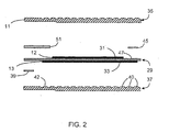
- FIG. 2 is an exploded partial cross section view of two electrolyte plates and one interconnect.
- FIG. 3 shows the cathode side of an interconnect.
- FIG. 4 shows the anode side of an interconnect.
- FIG. 5 is an exploded partial cross section view of a first embodiment of the current invention including an interconnect and two solid electrolytes.
- FIG. 6 is an exploded section view in cross section of an alternative embodiment of the current invention.
- FIG. 7 is a graph illustrating the effect of the invention on maximum power capacity of multi-cell stacks.
- the present invention relates to an electrochemical device with a means for conducting heat toward the outer edge of the interconnect comprising at least one metal having a high thermal conductivity selected from the group consisting of silver, gold, platinum, rhodium, and palladium.
- the means for conducting heat consists essentially of a metal selected from the group consisting of silver, gold, platinum, rhodium, palladium, and mixtures thereof.
- the means for conducting heat more preferably consists essentially of silver.
- a metal as defined herein can be an elemental metal but also includes metallic mixtures, metallic alloys, oxide phases, and mixtures thereof.
- the overall assembly and operation of the electrochemical cell stack is illustrated by the schematic isometric view of FIG. 1, which is not to scale.
- the cell stack is formed by a series of alternating solid electrolytes 95 with appropriate anodes and cathodes (not shown), interconnects 97 and insulating support material 99 with negative end plate 101 and positive end plate 103. Positive and negative electrical connections provide direct current to the stack, which operates at about 50 to 700 mV per cell.
- An exemplary device is disclosed in U.S. Pat. No. 6,042,703 assigned to Air Products and Chemicals, Inc., which document is incorporated herein by reference.
- the electrolytes are planar and are stacked in the axial direction.
- the stack shape of each plate in radial direction from a central opening can be formed from a variety of shapes including circular, square, rectangular or any other planar geometrical shape as required by the specific application.
- the preferred electrolyte plate and interconnect are, generally square with rounded corners as shown in FIG. 1.
- FIG. 1 Although this figure is not to scale, it can be seen that the solid electrolyte plates 95 are depicted as comparatively thin (in practice about 250 ⁇ m) as compared to the interconnects 97 that in general have a thickness about ten times the thickness of the solid electrolyte (in practice about 2500 ⁇ m).
- Oxygen-containing feed gas flows into one side of the stack as shown, flows across the cathode sides of the cells in a cross flow mode, and the oxygen-depleted gas exits the opposite side of the stack.
- the insulating supports 99 on the opposite sides of the stack direct gas in a cross flow mode through formation of suitable barriers and passages.
- a section through the stack shows the radial flow of oxygen product gas across the anode side of an interconnect toward the central opening 109.
- the central openings through the electrolyte plates and interconnects, in conjunction with cathode seals, form a central conduit in gas flow communication with the anode side of each cell.
- the central conduit connects with oxygen withdrawal conduit 111 which in turn is connected with a gas-tight seal (not shown) to bottom or positive end plate 103.
- a gas-tight seal (not shown) to bottom or positive end plate 103.
- an oxygen withdrawal conduit (not shown) could be connected at negative end plate 101. If desired, oxygen product can be withdrawn from both ends of the stack (not shown).
- the above electrochemical cell stack and the solid-state device can be fabricated by methods known in the art of ion conducting ceramics.
- the device can be made from any materials known in the art and generally used as solid electrolytes/membranes, electrodes, interconnects, and seals.
- FIG. 2 An exploded, partial sectional view of the solid-state device of the invention is illustrated in FIG. 2, based on the disclosure of U.S. Pat. No. 6,042,703 relating to flat plate designs of oxygen pumps in general.
- a single electrochemical cell is formed by an electrolyte membrane 29 having an anode 33 and a cathode 31, and the adjacent surfaces of two interconnects 35 and 37 joined by the appropriate gas-tight anode seal 39 and cathode seal 45 and electrical connections.
- an electrically insulating support is disposed between the cathode side of electrolyte plate 29 and the cathode side of interconnect 35 and a portion of this support is denoted as support 51.
- This support eliminates damaging stresses on electrolyte plate 29 when the gas pressure on the anode side of the electrochemical cell is greater than the gas pressure on the cathode side of the cell.
- Support 51 may or may not be gas tight, and is not applied continuously as explained in U.S. Pat. No. 6,042,703.
- Electrochemical cell stacks comprise a plurality of solid electrolyte membranes 29 having anode and cathode sides, said electrolytes being about 5 ⁇ m to 1 mm thick.
- the membranes may be formed from any suitable material known in the art.
- Anode layers 33 are formed on the anode side of the electrolytes of the cells and cathode layers 31 are formed on the cathode side of the electrolyte of the cells.
- the anode layers and the cathode layers may be formed from any oxidation resistant material, an alloy or a multicomponent mixed conducting oxide as known in the art. Both layers are typically applied independently in the form of a coating to the respective surface and can be attached e.g. by sintering of a paste applied by screen printing, sputtering, painting etc.
- the electrode thicknesses are typically in the range of 0.1 to 100 ⁇ m.
- the anode side of the interconnect 37 faces an anode layer 33.
- the cathode side of the interconnect 35 faces a cathode layer 31.
- the outer edge of interconnect 35 is denoted by the numeral 11.
- the outer edge 11, translocated about the outer periphery of the interconnect forms the outer surface of the interconnect.
- a current conductor (not shown), an electrically conductive material, may be formed on the anode and cathode such that it is between the anode 33 and the interconnect 37 and the cathode 31 and the interconnect 35, discussed further below.
- the interconnect is generally planar, gas impermeable, ionically nonconductive, and electrically conductive.
- the interconnect is prepared by conventional ceramic techniques known in the art. Sintering temperatures and procedures should be selected such that the sintered interconnect is free of connected through porosity, i.e. the network of pores do not allow flow of gases through the interconnect.
- the interconnect should have a final density of above 95% of theoretical density, preferably about 97% of theoretical density and more preferably of about 99% of theoretical density. Sintering temperatures of the interconnect of the invention are typically below 1350° C., preferably below 1300° C.
- the interconnects may be stackfired, hangfired, or fired by use of any other means to minimize interaction of the composition of matter or interconnect with a setter or form.
- Any suitable setter known in the art may be used. In any case it is desired to prevent sticking between the setter and the interconnect. Further, any reaction between the interconnect and the setter which results in warping or deformation of the interconnect or its surface should be avoided. Preferably, sintering conditions and lack of interactions would allow reuse of setters in interconnect production.
- the cathode side of an interconnect 1 is shown in plan view in FIG. 3, wherein the interconnect has a continuous peripheral flat surface 17 adjacent to the outer surface 15 and an opening 19 proximate the center of the interconnect.
- the interconnect generally has the same shape and size as the electrolyte plates.
- a continuous generally flat surface 21 surrounds opening 19. Opening 19 typically is the same or similar diameter as the openings in the electrolyte plates.
- raised areas 23 can be used, such as ribs, raised rectangular or triangular areas, and the like, which perform essentially the same function as raised areas 23.
- the tops of raised areas 23 and flat region 21 are generally coplanar, and this plane is above the plane formed by flat region 17.
- a continuous peripheral flat surface 25 is disposed adjacent the outer surface 15 of the interconnect, and a plurality of raised areas 27, characterized in this embodiment as frustoconical bosses or spherical segments with flattened tops, which also may be described as pins, are disposed between generally flat region 25 and opening 19.
- the continuous depressed or non-raised areas between the raised areas in conjunction with an adjacent electrolyte plate form a cavity or interconnected cavities in flow communication with opening 19.
- Alternatives to raised areas 27 can be used, such as ribs, channels, and the like, which perform essentially the same function as raised areas 27.
- Continuous grounding rib 28 surrounds the raised areas and electrically contacts a biasing electrode.
- the tops of raised areas 27, the top of grounding rib 28, and flat region 25 are generally coplanar.
- an electrically conducting material is applied to the surfaces of the raised areas on each interconnect as defined by elements 23 of FIG. 3 and 27 of FIG. 4 .
- this conducting material bonds to the raised areas on the interconnects and to the electrodes on each electrolyte plate.
- These so-called conformal layers provide operative electrical connections between the electrodes and the adjacent interconnects, and also provide mechanical support for the electrolyte plate.
- the conducting material is preferably silver initially applied as an ink before firing. As the conformal layers at each pin are not thermally connected, they are not effective to transfer heat to the outer surface of the stack. Further, this conformal layer does not extend into the flat peripheral region of the interconnect and do not provide heat dissipation toward the outer edge of the interconnect.
- an electrically conductive current collecting material may be applied to the electrode (anode and/or cathode) surface to distribute an electromotive force over the surface area of the electrode.
- the current collecting material is preferably a noble metal such as silver, a silver alloy, or platinum, and is applied to the electroded surface in a grid pattern. Since the current collector is less permeable to gas molecules, the grid pattern distributes the electromotive force over the surface of the electrode, yet leaves the majority of electrode surface area available for passage of gas molecules. The grid pattern also produces low sheet resistance to current passing through the current collector.
- the current collector is screenprinted onto the electrode surface. Other methods such as painting may be utilized to apply the current collector to the electrode surface.
- the electrochemical device includes a means for conducting heat.
- the means for conducting heat can be described as being provided between the outer edge of the interconnect and at least one of the outer edge of the anode and the outer edge of the cathode. Indicating that the means for conducting heat is between the edges means that a straight line from one edge to the other edge can be drawn through or to intersect with the means for conducting heat.
- the means for conducting heat comprises at least one metal selected from the group consisting of silver, gold, platinum, rhodium, and palladium.
- the means for conducting heat can be a layer on the cathode side or the anode side of the interconnect, or within the interconnect. The layer may or may not be continuous and may or may not extend all the way to the outer edge of the interconnect.
- the electrochemical device comprises (a) a first solid electrolyte 29 having an anode side, a cathode side, and an outer edge 14, (b) a first anode 33 situated adjacent to the anode side of the first solid electrolyte 29, the first anode having an outer edge 13 wherein the outer edge 13 is offset from the outer edge 14 of the first solid electrolyte 29, (c) a first cathode 31 situated adjacent to the cathode side of the first solid electrolyte 29, the first cathode 31 having an outer edge 12, wherein the outer edge 12 is offset from the outer edge 14 of the first solid electrolyte 29, (d) a second solid electrolyte 29' having an anode side, a cathode side, and an outer edge 14', (e) a second anode 33' situated adjacent to the anode side of the second solid electrolyte 29', the second anode having an outer edge 13' wherein the outer edge 13' is offset
- the means for conducting heat consists essentially of a metal selected from the group consisting of silver, gold, platinum, rhodium, palladium, and mixtures thereof.
- the means for conducting heat more preferably consists essentially of silver.
- the means for conducting heat or layer material is selected based on oxidation resistance, cost, and melting point.
- the thermal conductivity of the heat transfer layer is much higher than the multicomponent metal oxide interconnect material. While the multicomponent metal oxide interconnect material generally has a thermal conductivity of roughly 3 W/mK, silver, gold, platinum, rhodium, and palladium have thermal conductivities of about 428, 318, 71.1, 150, and 70 W/mK, respectively.
- the means for conducting heat 57 toward the outer edge 11 is applied to the interconnect 35 as a layer contiguous with at least a portion of the cathode side of the interconnect.
- the outer edge of the cathode 31' is denoted 12' and the outer edge of the anode 33' is denoted 13'.
- This embodiment clearly shows the means for conducting heat between the outer edge of the cathode 12' and the outer edge 11 of the interconnect 35.
- FIG. 5 is an exploded view) that it is possible to draw a straight line from the outer edge 12' of the cathode 31' to the outer edge 11 of the interconnect 35 where the line passes through or intersects with the means for conducting heat 57.
- the layer can also be applied to the anode side of the interconnect.
- the means for conducting heat is between the outer edge 13 of the anode 33 and the outer edge 11 of the interconnect 35. It is possible to draw a straight line from the outer edge 13 of the anode 33 to the outer edge 11 of the interconnect 35 where the line passes through or intersects with the means for conducting heat.
- the layer is shown contiguous with the peripheral flat surface of the interconnect. Greater benefit is provided when the heat transfer layer provides heat communication from within the stack to the outer surface of the stack for heat removal. It is therefore preferable for the heat transfer layer to cover at least a portion of and more preferably all of the outer, peripheral flat surface of the interconnect to prevent a thermally insulating zone near the outer edges of the stack. Most preferably, the layer covers largely all, greater than 75%, of the surface of the interconnect as shown in FIG. 5.
- the means for conducting heat does not extend in the small region adjacent to the cathode seal 45. A heat transfer layer contiguous with the cathode seal may weaken the seal and oxygen may diffuse through the layer.
- any amount of metal sufficient to provide a measurable effect in increased heat transfer toward the edge of the interconnect decreases thermal stresses and probability for failure, with thicker layers providing more benefit than thin layers.
- the upper limit depends on several potential factors such as the ability to prevent spalling, the cost of the metal, or the impact on gas flow path dimensions.
- the means for conducting heat can be formed as a layer by spraying or brushing a metal-containing slurry on the at least one surface of the interconnect and evaporating the solvent leaving a layer of metal, or by contacting a metal containing foil to the at least one side of the interconnect with or without adhesive.
- the heat transfer layer is applied by spraying means.
- an ink is first prepared.
- the ink comprises silver powder having an average particle size of about 3 mils (.003 inches), cyanoguanidine, oleic acid, terpineol, and V-006 (a mixture of terpineol and resin available from Heraeus), having mass percentages of about 79.5, 0.5, 0.5, 11.8, 7.7, respectively.
- This ink is mixed and then thinned with 2-propanol before spraying on the surface of the interconnect.
- the thinned mixture is about 88.9 mass percent ink with the balance 2-propanol.
- Silver-containing inks/pastes are also commercially available such as Heraeus CL80-8487, Metech PCC11902, Dupont 7342, and ESL Electro-Science 9990.
- the heat transfer layer is applied to the interconnect using a low volume low pressure spray valve, such as manufactured by EFD, Inc.
- the spray valve provides a fan pattern that spreads about 6.5 inches long and 0.5 -1 inches wide.
- the parts are loaded onto a motorized stage that passes the parts underneath the spray head.
- the weight laydown can be varied by adjusting the speed of the stage up or down until a dry-fired coating of desired weight is obtained.
- the interconnect with "wet" heat transfer layer is then placed in a kiln and fired.
- the kiln is programmed to ramp the temperature at a rate of 145°C/hr up to 750°C, hold at 750°C for an hour, and then ramp down at a rate of about 90.6°C to room temperature.
- Anode seal 39 and cathode seal 45 form gas-tight seals between the respective areas of the electrolyte plate and the interconnect when the stack is assembled.
- the gas tight seals maintain product gas purity and prevent product loss, and prevent or minimize the mixing of feed and product streams.
- the seals prevent or minimize gas mixing due to pressure differential and/or gas composition differential among the feed, permeate, and nonpermeate streams.
- the gas-tight seals also serve to bond the electrolyte plates and interconnects together in the stack.
- the seals can be cofired and bonded directly to the electrolyte plates and interconnects, or alternatively one or more additional cofired materials can be used.
- a preferred material for seals 39 and 45 is a glass-ceramic derived from a lithium aluminosilicate (LAS) glass, which is a material known in the art for use in seals as described for example in an article by T. J. Headly and R. E. Loehman entitled "Crystallization of a Glass-Ceramic by Epitaxial Growth” in Journal of the American Ceramic Society, Vol. 67, pp. 620-625, 1984.
- LAS lithium aluminosilicate
- FIG. 6 An exploded view of another embodiment is illustrated in FIG. 6, showing a layer 58 formed within the interconnect.
- the layer is shown to extend only part way through the interconnect.
- the interconnect can be formed by including a plurality of silver ribbons, rods, bars, and the like, when forming the interconnect to create a composite-like structure. Numbered features in FIG. 6 represent correspondingly numbered features in FIG. 5.
- the means for conducting heat is between the outer edge 13 of the anode 33 and the outer edge 11 of the interconnect 35. It is possible to draw a straight line from the outer edge 13 of the anode 33 to some point on the outer edge 11 of the interconnect 35 where the line passes through or intersects with the means for conducting heat.
- the means for conducting heat is also between the outer edge 12' of the cathode 31' and the outer edge 11 of the interconnect 35. It is possible to draw a straight line from the outer edge 12' to some point (above the means for conducting heat 58) on the outer edge 11 where the line passes through or intersects with the means for conducting heat.
- Air and oxygen gas passages may be fabricated within the interconnect in a wide variety of shapes, in cross-section, such as rectangular, trapezoidal, semi-circular and the like.
- the depth and spacing of the passages may be widely varied and optimum designs may be assessed for a given application without undue experimentation. For example, the depth of a passage may decrease with distance traversed across the surface of the electrode layer in order to increase the diffusional flux to the electrode surface of the component gas being transported through the electrolyte.
- FIG. 7 illustrates the beneficial impact of the means for conducting heat toward the outer edge of the interconnect.
- All of the stacks had silver conformal layers present in the pin region, including the cases with 0 mg/cm 2 .
- Stacks having 25, 32, and 50 cells were tested where average amounts of silver coating was varied (0, 10, 30 and 50 mg/cm 2 ). For each case (datum point), all of the cells in the stack had the same amount of silver coating.
- FIG. 7 shows the maximum power resulting in failure of the device versus the amount of silver applied to each interconnect. A break or crack in the electrolyte plate resulted in loss of oxygen product and hence in failure of the device.
Landscapes
- Chemical & Material Sciences (AREA)
- Analytical Chemistry (AREA)
- Organic Chemistry (AREA)
- Inorganic Chemistry (AREA)
- Electrochemistry (AREA)
- Engineering & Computer Science (AREA)
- General Chemical & Material Sciences (AREA)
- Oil, Petroleum & Natural Gas (AREA)
- Chemical Kinetics & Catalysis (AREA)
- Fuel Cell (AREA)
- Oxygen, Ozone, And Oxides In General (AREA)
- Physical Or Chemical Processes And Apparatus (AREA)
Applications Claiming Priority (1)
| Application Number | Priority Date | Filing Date | Title |
|---|---|---|---|
| US10/966,597 US7427339B2 (en) | 2004-10-15 | 2004-10-15 | Heat conducting metal layer for ion conductor stack |
Publications (2)
| Publication Number | Publication Date |
|---|---|
| EP1647323A2 true EP1647323A2 (de) | 2006-04-19 |
| EP1647323A3 EP1647323A3 (de) | 2007-10-03 |
Family
ID=35531513
Family Applications (1)
| Application Number | Title | Priority Date | Filing Date |
|---|---|---|---|
| EP05022212A Ceased EP1647323A3 (de) | 2004-10-15 | 2005-10-12 | Wärmeableitende metalische Lage für Ionenleiter mit mehreren Schichten |
Country Status (2)
| Country | Link |
|---|---|
| US (1) | US7427339B2 (de) |
| EP (1) | EP1647323A3 (de) |
Families Citing this family (2)
| Publication number | Priority date | Publication date | Assignee | Title |
|---|---|---|---|---|
| GB201506484D0 (en) * | 2015-04-16 | 2015-06-03 | Rolls Royce Plc | A method of sintering |
| TWI766637B (zh) | 2021-04-06 | 2022-06-01 | 國立臺北科技大學 | 平板型固態電解質氧氣分離器 |
Citations (7)
| Publication number | Priority date | Publication date | Assignee | Title |
|---|---|---|---|---|
| US4885142A (en) | 1985-10-28 | 1989-12-05 | California Institute Of Technology | Apparatus in the form of a disk for the separation of oxygen from other gases and/or for the pumping of oxygen and the method of removing the oxygen |
| US5186806A (en) | 1990-12-31 | 1993-02-16 | California Institute Of Technology | Ceramic distribution members for solid state electrolyte cells and method of producing |
| US5298138A (en) | 1992-02-28 | 1994-03-29 | Ceramatec, Inc. | Solid electrolyte ion conducting device |
| EP0682379A1 (de) | 1994-05-09 | 1995-11-15 | Air Products And Chemicals, Inc. | Flachaufbau in Serien für Sauerstoffpumpe mit festem Elektrolyt |
| US5868918A (en) | 1996-09-26 | 1999-02-09 | Air Products And Chemicals, Inc. | Method for separating oxygen from an oxygen-containing gas |
| EP0983786A2 (de) | 1998-08-28 | 2000-03-08 | Air Products And Chemicals, Inc. | Trennung von Sauerstoff aus einem sauerstoffhaltigen Gas |
| US20030022048A1 (en) | 2001-04-27 | 2003-01-30 | Meixner Donald Laurence | Electrochemical solid-state device comprising b-site rich lanthanum calcium manganite |
Family Cites Families (6)
| Publication number | Priority date | Publication date | Assignee | Title |
|---|---|---|---|---|
| WO1992000934A2 (en) | 1990-07-06 | 1992-01-23 | Igr Enterprises, Inc. | Ductile ceramic composites |
| EP0565790B1 (de) | 1992-04-16 | 1996-11-06 | Invacare Corporation | Sauerstoffanreichungsgerät mit Verwendung einer elektrochemischen Zelle |
| US6132573A (en) * | 1997-12-05 | 2000-10-17 | Igr Enterprises, Inc. | Ceramic composite electrolytic device and methods for manufacture thereof |
| AUPQ078899A0 (en) * | 1999-06-04 | 1999-06-24 | Ceramic Fuel Cells Limited | A fuel cell gas separator |
| US20040219423A1 (en) | 2001-04-27 | 2004-11-04 | Tunney Cathal Joseph | Metal-supported solid electrolyte electrochemical cell and multi cell reactors incorporating same |
| US7037617B2 (en) * | 2002-08-21 | 2006-05-02 | Delphi Technologies, Inc. | Conductive coatings for PEM fuel cell electrodes |
-
2004
- 2004-10-15 US US10/966,597 patent/US7427339B2/en active Active
-
2005
- 2005-10-12 EP EP05022212A patent/EP1647323A3/de not_active Ceased
Patent Citations (11)
| Publication number | Priority date | Publication date | Assignee | Title |
|---|---|---|---|---|
| US4885142A (en) | 1985-10-28 | 1989-12-05 | California Institute Of Technology | Apparatus in the form of a disk for the separation of oxygen from other gases and/or for the pumping of oxygen and the method of removing the oxygen |
| US5186806A (en) | 1990-12-31 | 1993-02-16 | California Institute Of Technology | Ceramic distribution members for solid state electrolyte cells and method of producing |
| US5298138A (en) | 1992-02-28 | 1994-03-29 | Ceramatec, Inc. | Solid electrolyte ion conducting device |
| US5750279A (en) | 1992-02-28 | 1998-05-12 | Air Products And Chemicals, Inc. | Series planar design for solid electrolyte oxygen pump |
| EP0682379A1 (de) | 1994-05-09 | 1995-11-15 | Air Products And Chemicals, Inc. | Flachaufbau in Serien für Sauerstoffpumpe mit festem Elektrolyt |
| US5868918A (en) | 1996-09-26 | 1999-02-09 | Air Products And Chemicals, Inc. | Method for separating oxygen from an oxygen-containing gas |
| US6042703A (en) | 1996-09-26 | 2000-03-28 | Air Products And Chemicals, Inc. | Ion conductor stack with offset seals and biasing electrodes |
| US6090265A (en) | 1996-09-26 | 2000-07-18 | Air Products And Chemicals, Inc. | Separation of oxygen from oxygen-containing gas |
| US6117288A (en) | 1996-09-26 | 2000-09-12 | Air Products And Chemicals, Inc. | Insulating support for ion conductor stack |
| EP0983786A2 (de) | 1998-08-28 | 2000-03-08 | Air Products And Chemicals, Inc. | Trennung von Sauerstoff aus einem sauerstoffhaltigen Gas |
| US20030022048A1 (en) | 2001-04-27 | 2003-01-30 | Meixner Donald Laurence | Electrochemical solid-state device comprising b-site rich lanthanum calcium manganite |
Non-Patent Citations (2)
| Title |
|---|
| LAU: "Three-dimensional numerical modeling of heat and mass transfer in a ceramic oxygen generator (COG", NUMERICAL HEAT TRANSFER, vol. 41, 2002, pages 149 - 164 |
| T. J. HEADLY; R. E. LOEHMAN: "Crystallization of a Glass-Ceramic by Epitaxial Growth", JOURNAL OF THE AMERICAN CERAMIC SOCIETY, vol. 67, 1984, pages 620 - 625 |
Also Published As
| Publication number | Publication date |
|---|---|
| EP1647323A3 (de) | 2007-10-03 |
| US7427339B2 (en) | 2008-09-23 |
| US20060083974A1 (en) | 2006-04-20 |
Similar Documents
| Publication | Publication Date | Title |
|---|---|---|
| EP0682379B1 (de) | Flachaufbau in Serien für Sauerstoffpumpe mit festem Elektrolyt | |
| JP4472914B2 (ja) | 集積流路を有する高性能セラミック燃料電池のインターコネクト及びその作製方法 | |
| KR100279495B1 (ko) | 오프셋시일및바이어스전극을구비한이온전도체스택 | |
| US6972161B2 (en) | Fuel cell assembly and method of making the same | |
| EP1261059B1 (de) | Zellen-Plattenstruktur für Brennstoffzelle, Verfahren zu ihrer Herstellung und Festelektrolytbrennstoffzelle | |
| US20080107948A1 (en) | High Specific Power Solid Oxide Fuel Cell Stack | |
| KR101162806B1 (ko) | 자가-지지형 세라믹 멤브레인 및 전기화학 전지 및 이것을포함하는 전기화학 전지 적층체 | |
| JP2012049143A (ja) | 電気化学的電池スタック組立体 | |
| US6090265A (en) | Separation of oxygen from oxygen-containing gas | |
| US20080206618A1 (en) | Electrochemical devices and electrochemical apparatus | |
| JPH11297344A (ja) | ハニカム一体構造の固体電解質型燃料電池 | |
| JP2002329511A (ja) | 固体電解質型燃料電池用スタック及び固体電解質型燃料電池 | |
| KR101385088B1 (ko) | 연료전지 및 연료전지의 제조 방법 | |
| EP1407502B1 (de) | Dichtung für einen brennstoffzellenstapel | |
| US7427339B2 (en) | Heat conducting metal layer for ion conductor stack | |
| JPH07245113A (ja) | 燃料電池用固体電解質及びこれを用いた固体電解質型燃料電池 | |
| JPH10189024A (ja) | ハニカム一体構造の固体電解質型燃料電池 | |
| JP2004319266A (ja) | 固体酸化物形燃料電池のシール構造体及びシール方法 | |
| EP4372851A2 (de) | Verfahren zur herstellung einer verbindung für einen stapel einer elektrochemischen vorrichtung mittels spark-plasma-sintern | |
| JPH06150958A (ja) | 固体電解質燃料電池 | |
| JP7016334B2 (ja) | 電気化学反応単セル、および、電気化学反応セルスタック | |
| JP2003197204A (ja) | 電気化学装置 | |
| JP6774230B2 (ja) | 集電部材−電気化学反応単セル複合体および電気化学反応セルスタック | |
| JPH076776A (ja) | 固体電解質型燃料電池のスタック | |
| AU2002344720B2 (en) | Seal for a fuel cell stack |
Legal Events
| Date | Code | Title | Description |
|---|---|---|---|
| PUAI | Public reference made under article 153(3) epc to a published international application that has entered the european phase |
Free format text: ORIGINAL CODE: 0009012 |
|
| AK | Designated contracting states |
Kind code of ref document: A2 Designated state(s): AT BE BG CH CY CZ DE DK EE ES FI FR GB GR HU IE IS IT LI LT LU LV MC NL PL PT RO SE SI SK TR |
|
| AX | Request for extension of the european patent |
Extension state: AL BA HR MK YU |
|
| PUAL | Search report despatched |
Free format text: ORIGINAL CODE: 0009013 |
|
| AK | Designated contracting states |
Kind code of ref document: A3 Designated state(s): AT BE BG CH CY CZ DE DK EE ES FI FR GB GR HU IE IS IT LI LT LU LV MC NL PL PT RO SE SI SK TR |
|
| AX | Request for extension of the european patent |
Extension state: AL BA HR MK YU |
|
| RIC1 | Information provided on ipc code assigned before grant |
Ipc: C25B 1/02 20060101ALI20070827BHEP Ipc: C01B 13/02 20060101ALI20070827BHEP Ipc: B01D 53/32 20060101AFI20060126BHEP |
|
| 17P | Request for examination filed |
Effective date: 20071030 |
|
| 17Q | First examination report despatched |
Effective date: 20071213 |
|
| AKX | Designation fees paid |
Designated state(s): AT BE BG CH CY CZ DE DK EE ES FI FR GB GR HU IE IS IT LI LT LU LV MC NL PL PT RO SE SI SK TR |
|
| STAA | Information on the status of an ep patent application or granted ep patent |
Free format text: STATUS: THE APPLICATION HAS BEEN REFUSED |
|
| 18R | Application refused |
Effective date: 20090730 |