EP2044465B1 - Seismic data processing - Google Patents
Seismic data processing Download PDFInfo
- Publication number
- EP2044465B1 EP2044465B1 EP07812428.6A EP07812428A EP2044465B1 EP 2044465 B1 EP2044465 B1 EP 2044465B1 EP 07812428 A EP07812428 A EP 07812428A EP 2044465 B1 EP2044465 B1 EP 2044465B1
- Authority
- EP
- European Patent Office
- Prior art keywords
- going wavefields
- streamer
- receiver
- streamers
- seismic data
- Prior art date
- Legal status (The legal status is an assumption and is not a legal conclusion. Google has not performed a legal analysis and makes no representation as to the accuracy of the status listed.)
- Not-in-force
Links
- 238000012545 processing Methods 0.000 title claims description 17
- 238000000034 method Methods 0.000 claims description 25
- 238000000926 separation method Methods 0.000 claims description 13
- 239000002245 particle Substances 0.000 claims description 7
- 230000006870 function Effects 0.000 claims description 3
- 238000005516 engineering process Methods 0.000 description 14
- XLYOFNOQVPJJNP-UHFFFAOYSA-N water Substances O XLYOFNOQVPJJNP-UHFFFAOYSA-N 0.000 description 7
- 238000000354 decomposition reaction Methods 0.000 description 6
- 230000015572 biosynthetic process Effects 0.000 description 4
- 238000010586 diagram Methods 0.000 description 4
- 238000005755 formation reaction Methods 0.000 description 4
- 239000004215 Carbon black (E152) Substances 0.000 description 3
- 229930195733 hydrocarbon Natural products 0.000 description 3
- 150000002430 hydrocarbons Chemical class 0.000 description 3
- 238000005457 optimization Methods 0.000 description 3
- 238000004891 communication Methods 0.000 description 2
- 238000005259 measurement Methods 0.000 description 2
- 230000003287 optical effect Effects 0.000 description 2
- 230000003044 adaptive effect Effects 0.000 description 1
- 238000004590 computer program Methods 0.000 description 1
- 230000000694 effects Effects 0.000 description 1
- 238000001914 filtration Methods 0.000 description 1
- 230000002452 interceptive effect Effects 0.000 description 1
- 238000005070 sampling Methods 0.000 description 1
- 238000012546 transfer Methods 0.000 description 1
Images


Classifications
-
- G—PHYSICS
- G01—MEASURING; TESTING
- G01V—GEOPHYSICS; GRAVITATIONAL MEASUREMENTS; DETECTING MASSES OR OBJECTS; TAGS
- G01V1/00—Seismology; Seismic or acoustic prospecting or detecting
- G01V1/28—Processing seismic data, e.g. for interpretation or for event detection
- G01V1/36—Effecting static or dynamic corrections on records, e.g. correcting spread; Correlating seismic signals; Eliminating effects of unwanted energy
-
- G—PHYSICS
- G01—MEASURING; TESTING
- G01V—GEOPHYSICS; GRAVITATIONAL MEASUREMENTS; DETECTING MASSES OR OBJECTS; TAGS
- G01V2210/00—Details of seismic processing or analysis
- G01V2210/10—Aspects of acoustic signal generation or detection
- G01V2210/12—Signal generation
- G01V2210/129—Source location
- G01V2210/1293—Sea
-
- G—PHYSICS
- G01—MEASURING; TESTING
- G01V—GEOPHYSICS; GRAVITATIONAL MEASUREMENTS; DETECTING MASSES OR OBJECTS; TAGS
- G01V2210/00—Details of seismic processing or analysis
- G01V2210/10—Aspects of acoustic signal generation or detection
- G01V2210/14—Signal detection
- G01V2210/142—Receiver location
- G01V2210/1423—Sea
-
- G—PHYSICS
- G01—MEASURING; TESTING
- G01V—GEOPHYSICS; GRAVITATIONAL MEASUREMENTS; DETECTING MASSES OR OBJECTS; TAGS
- G01V2210/00—Details of seismic processing or analysis
- G01V2210/50—Corrections or adjustments related to wave propagation
- G01V2210/57—Trace interpolation or extrapolation, e.g. for virtual receiver; Anti-aliasing for missing receivers
Definitions
- Implementations of various technologies described herein generally relate to seismic data processing, and more particularly, processing seismic data using filters, such as 2D filters.
- Seismic exploration is widely used to locate and/or survey subterranean geological formations for hydrocarbon deposits. Since many commercially valuable hydrocarbon deposits are located beneath bodies of water, various types of marine seismic surveys have been developed. In a typical marine seismic survey, seismic streamers are towed behind a survey vessel. The seismic streamers may be several thousand meters long and contain a large number of sensors, such as hydrophones, geophones, and associated electronic equipment, which are distributed along the length of the each seismic streamer cable. The survey vessel also includes one or more seismic sources, such as air guns and the like.
- acoustic signals commonly referred to as "shots,” produced by the one or more seismic sources are directed down through the water into strata beneath the water bottom, where they are reflected from the various subterranean geological formations. Reflected signals are received by the sensors, digitized, and then transmitted to the survey vessel. The digitized signals are referred to as "traces" and are recorded and at least partially processed by a signal processing unit deployed on the survey vessel. The ultimate aim of this process is to build up a representation of the subterranean geological formations beneath the streamers. Analysis of the representation may indicate probable locations of hydrocarbon deposits in the subterranean geological formations.
- the seismic streamers may be in an over/under configuration, i.e., one set of streamers being suspended above another set of streamers. Streamers in an over/under configuration may be towed much deeper than streamers in a conventional single configuration. As a result, broadband data (i.e., both high and low frequencies) may be acquired and the recorded data may be easily separated into up-going wavefields and down-going wavefields.
- broadband data i.e., both high and low frequencies
- O.Eiken et al. propose, in "A proven method for acquiring highly repeatable towed streamer seismic data", Geophysics Vol.68, No. 4, pp1303-1309 (2003 ), a method of processing seismic data comprising selecting a predefined line, picking traces closest to the predefined line, and measuring the repeatability between seismic surveys.
- the seismic data are processed by creating a fictitious source-receiver line connecting a source with a receiver location of interest, projecting one or more receiver locations adjacent the receiver location of interest onto the fictitious source-receiver line, and decomposing seismic data on the receiver locations disposed on the fictitious source-receiver line into up-going wavefields and down-going wavefields.
- the seismic data are processed by: (a) receiving one or more values of seismic survey parameters, (b) creating a fictitious source-receiver line connecting a source with a receiver location of interest, (c) projecting one or more receiver locations adjacent the receiver location of interest onto the fictitious source-receiver line, (d) decomposing seismic data on the receiver locations disposed on the fictitious source-receiver line into up-going wavefields and down-going wavefields using the one or more values, and (e) determining whether the up-going wavefields are consistent with the down-going wavefields.
- the seismic data are processed by receiving one or more parameters of an over/under streamer pair, decomposing seismic data into up-going wavefields and down-going wavefields using the one or more parameters, and determining whether the up-going wavefields are consistent with the down-going wavefields.
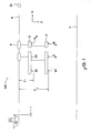
- FIG. 1 illustrates a schematic diagram of a marine seismic survey 100 in accordance with implementations of various technologies described herein.
- the marine seismic survey 100 includes a source array 1 configured for emitting seismic energy, and a first streamer 2 and a second streamer 2' both suspended within a water column at different depths below the surface of the sea 6.
- the second streamer 2' is suspended below the first streamer 2.
- the second streamer 2' is deployed to be nominally vertically below the first streamer 2; however, the action of tides and currents may mean that the second streamer 2' is not always exactly vertically below the first streamer 2.
- the streamers are deployed such that the first streamer 2 is deployed at a nominal depth Z 1 below the surface 6 of the sea and the second streamer 2' is deployed at a nominal depth Z 2 (where Z 2 > Z 1 ) below the surface 6 of the water column.
- the action of tides and currents and the effect of surface waves may mean that the first and second streamers 2, 2' are not always at exactly their nominal depths.
- the term "over” is typically associated with the shallower streamers, e.g., the first streamer 2
- the term "under” is typically associated with the deeper streamers, e.g., the second streamer 2'.
- a plurality of pressure sensors are disposed along each streamer, with the first streamer 2 having pressure sensors S1, S2... SN up to a total of N pressure sensors and the second streamer 2' having pressure sensors S1', S2'...SM up to a total of M pressure sensors.
- the streamers are suspended from one or more floats 8 so that all the pressure sensors of the streamer are at the same depth in a flat sea.
- the streamers have been described as having pressure sensors disposed thereon, it should be understood that in some implementations the one or both streamers may include other types of receivers, such as particle velocity sensors and the like.
- the marine seismic survey 100 further includes a processing apparatus 20 for processing seismic data acquired by the pressure sensors on the streamers 2, 2' as a result of actuating the source array 1 to emit seismic energy.
- the processing apparatus 20 may be located, for example, on shore, on the towing vessel, or on another vessel. Data acquired at the sensors on the streamers may for example be transmitted to a storage means (for example located on the towing vessel) by, for example, an electrical, optical or wireless link (not shown), and may subsequently be passed to the processing apparatus. Alternatively, data acquired at the sensors may be stored for subsequent retrieval in storage means provided on the streamers.
- the source array 1 may be an array of airguns or any other type of emitters, such as marine vibrator units and the like. Energy emitted from the source array 1 maybe reflected by the seabed 3 or by other reflectors (not shown) below the seabed 3 and may then be detected by the seismic receivers 2, 2'.
- FIG. 2 illustrates a flow diagram of a method 200 for processing seismic data in accordance with implementations of various technologies described herein.
- seismic data acquired using over/under streamer configuration
- the seismic data may be acquired by other receiver streamer configurations, such as conventional single streamers, over/under configuration having more than two streamers at various depths, multicomponent streamers and the like.
- a multicomponent streamer as used herein may be defined as having receiver stations, each having one or more orthogonally oriented particle sensors (e.g., geophones or accelerometers) and a hydrophone.
- initial values for the vertical distance (or separation) between the first streamer 2 and the second streamer 2' may be provided. These initial values may, if provided, later be optimized at step 260, which will be described in more detail in the following paragraphs. In one implementation, the initial values further include the inline (or horizontal) separation between the streamers. The initial values may be obtained from the seismic survey vessel's navigation system, a previous shot, or acquisition log.
- the initial values are discussed herein as including either the vertical separation between the first streamer 2 and the second streamer 2', the inline separation between the streamers or both, it should be understood that in some implementations the initial values may include other seismic survey parameters, such as deviations of streamer locations in the over/under pair in the cross-line direction, calibration filters for pressure sensors and the like for over/under streamers; exact wave-height over the streamer as a function of time and pressure sensor location, calibration filters for pressure sensors and the like for (conventional) single streamer configurations; depth of streamer, rotation angles of particle motion sensors, calibration filters for particle motion sensors, calibration filters for pressure sensors and the like for multicomponent streamer configurations.
- seismic survey parameters such as deviations of streamer locations in the over/under pair in the cross-line direction, calibration filters for pressure sensors and the like for over/under streamers; exact wave-height over the streamer as a function of time and pressure sensor location, calibration filters for pressure sensors and the like for (conventional) single streamer configurations; depth of streamer
- a fictitious source-receiver line through a pressure sensor location of interest is created.
- Figure 3 illustrates an example of a fictitious source-receiver line 300 connecting the source 1 to pressure sensor S4, which is the pressure sensor of interest.
- one or more pressure sensor locations adjacent to the pressure sensor location of interest is/are projected to the fictitious source-receiver line.
- the location of pressure sensors S1, S2, S3, S5, S6 and S7 are projected onto the fictitious source-receiver line 300.
- the adjacent pressure sensors are projected perpendicularly onto the fictitious source-receiver line.
- the adjacent pressure sensors are projected onto the source-receiver line via the shortest arc that maintains the true source-receiver offset such that this arc crosses the fictitious source-receiver line.
- the number of adjacent pressure sensor locations projected onto the fictitious source-receiver line determines the size of the spatial aperture of the filter that may be used to perform the decomposition step, described in the paragraphs below.
- not all of the adjacent pressure sensor locations from the first and second streamers 2, 2' set are projected onto the fictitious source-receiver line. That is, the spatial aperture may be based on less than the total number of pressure sensors on the first and second streamers 2, 2', thereby making the spatial aperture compact.
- the fictitious source-receiver line having the pressure sensor location of interest and all the pressure sensor locations projected thereon may be used to represent both first and second streamers pair 2, 2'.
- the spacing between the pressure sensor locations on the fictitious source-receiver line may be smaller than the spacing between the pressure sensor locations on the first and second streamers 2, 2'.
- the seismic data on the fictitious source-receiver line are assumed to be substantially the same as the seismic data on the first and second streamers 2, 2' set.
- 2D filters may be used to decompose the projected seismic data on the fictitious source-receiver line.
- the 2D filters may be functions of k r , the horizontal wavenumber, along the fictitious source-receiver line.
- the projected seismic data may be decomposed into up-going wavefields and down-going wavefields along the fictitious source-receiver line using the initial values obtained at step 210.
- the seismic data are decomposed using Equation (1) as shown below:
- P U ⁇ k r z 1 exp i ⁇ k z ⁇ ⁇ ⁇ z ⁇ P ⁇ k r z 2 - exp 2 ⁇ i ⁇ k z ⁇ ⁇ ⁇ z ⁇ P ⁇ k r z 1 1 - exp 2 ⁇ i ⁇ k z ⁇ ⁇ ⁇ z Equation (1) is configured to provide the up-going pressure P U at the upper streamer in an over/under streamer pair given the pressure recordings P along both streamers. Decomposition using Equation (1) is described in more detail in Amundsen, L., 1993, WAVENUMBER-BASED FILTERING OF MARINE POINT-SOURCE DATA, Geophysics, 58, 1335-1348 .
- the seismic data are decomposed using Equations (2) and (3) as shown below:
- V z ⁇ k r z 1 i ⁇ k z ⁇ ⁇ ⁇ ⁇ cot k z ⁇ ⁇ ⁇ z ⁇ P ⁇ k r z 1 - i ⁇ k z ⁇ ⁇ ⁇ sin k z ⁇ ⁇ ⁇ z ⁇ P ⁇ k r z 2
- P U ⁇ k r z 1 1 2 ⁇ P ⁇ k r z 1 - ⁇ ⁇ k z ⁇ V z ⁇ k r z 1
- k z ⁇ / c 2 - k r 2
- Equation (2) is configured to provide the vertical pressure gradient between the first streamer 2 and the second streamers 2', while Equation (3) is configured to compute the up-going pressure.
- decomposition using Equation (3) may be performed by applying the method described in Amundsen, L., Rosten, T., Robertson, J. O. A. and Kragh, E., 2003, ROUGH-SEA DEGHOSTING OF STREAMER SEISMIC DATA USING PRESSURE GRADIENT APPROXIMATIONS: GEOPHYSICS, Soc. of Expl. Geophys., 70, V1-V9 , to solve the second term on the right hand side of Equation (3).
- G 2 - i ⁇ k z ⁇ ⁇ ⁇ sin k z ⁇ ⁇ ⁇ z
- Equation (4) may be efficiently implemented in the space-frequency domain using only a short spatial aperture filter, which may also be referred to as a compact filter.
- a determination may be made as to whether the up-going wavefields are consistent with the down-going wavefields. This determination may be made using various criterion, such as one described in Muijs, R., Robertsson, J. O. A., and Holliger, K., DATA-DRIVEN ADAPTIVE DECOMPOSITION OF MULTICOMPONENT SEABED RECORDINGS, Geophysics,69, 1329-1337, 2004 .
- the initial values obtained at step 210 may be optimized (step 260). During this optimization, either the vertical distance (or separation) between the first streamer 2 and the second streamer 2', the inline (or horizontal) separation between the streamers, or both, may be modified. Once optimized, the decomposition step at step 240 may be repeated using the modified values. Steps 240-260 may be repeated until the up-going wavefields and the down-going wavefields are consistent.
- optimization step is described as modifying either the vertical separation between the first streamer 2 and the second streamer 2', the inline separation between the streamers or both, it should be understood that in some implementations the optimization step may modify other seismic survey parameters that would affect the consistency between up-going wavefields and down-going wavefields, as previously mentioned in the above paragraphs.
- a determination may be made as to whether a fictitious source-receiver line through another pressure sensor location of interest needs to be created. If there is still another fictitious source-receiver line through another pressure sensor location of interest that needs to be created, then processing returns to step 210. In this manner, all pressure locations on the first streamer 2, the second streamer 2' or both may be filtered using method 200 described herein. As a result of using implementations of various technologies described herein, any insufficient sampling in the crossline direction may be compensated.
- FIG. 4 illustrates a computer network 400 into which implementations of various technologies described herein may be implemented.
- the computer network 400 includes a system computer 430, which may be implemented as any conventional personal computer or server.
- system computer 430 may be implemented as any conventional personal computer or server.
- implementations of various technologies described herein may be practiced in other computer system configurations, including hypertext transfer protocol (HTTP) servers, hand-held devices, multiprocessor systems, microprocessor-based or programmable consumer electronics, network PCs, minicomputers, mainframe computers, and the like.
- HTTP hypertext transfer protocol
- disk storage devices 429, 431, and 433, which may be external hard disk storage devices. It is contemplated that disk storage devices 429, 431, and 433 are conventional hard disk drives, and as such, will be implemented by way of a local area network or by remote access. Of course, while disk storage devices 429, 431, and 433 are illustrated as separate devices, a single disk storage device may be used to store any and all of the program instructions, measurement data, and results as desired.
- seismic data from the receivers are stored in disk storage device 431.
- the system computer 430 retrieves the appropriate data from the disk storage device 431 to process seismic data according to program instructions that correspond to implementations of various technologies described herein.
- the program instructions may be written in a computer programming language, such as C++, Java and the like.
- the program instructions are stored in a computer-readable memory, such as program disk storage device 433.
- the memory medium storing the program instructions may be of any conventional type used for the storage of computer programs, including hard disk drives, floppy disks, CD-ROMs and other optical media, magnetic tape, and the like.
- system computer 430 presents output primarily onto graphics display 427, or alternatively via printer 428.
- the system computer 430 may store the results of the methods described above on disk storage 429, for later use and further analysis.
- the keyboard 426 and the pointing device (e.g., a mouse, trackball, or the like) 425 may be provided with the system computer 430 to enable interactive operation.
- the system computer 430 may be located at a data center remote from the survey region.
- the system computer 430 may be in communication with the receivers (either directly or via a recording unit, not shown), to receive signals indicative of the reflected seismic energy. These signals, after conventional formatting and other initial processing, are stored by the system computer 430 as digital data in the disk storage 431 for subsequent retrieval and processing in the manner described above. While Figure 4 illustrates the disk storage 431 as directly connected to the system computer 430, it is also contemplated that the disk storage device 431 may be accessible through a local area network or by remote access.
- disk storage devices 429, 431 are illustrated as separate devices for storing input seismic data and analysis results, the disk storage devices 429, 431 may be implemented within a single disk drive (either together with or separately from program disk storage device 433), or in any other conventional manner as will be fully understood by one of skill in the art having reference to this specification.
Landscapes
- Engineering & Computer Science (AREA)
- Remote Sensing (AREA)
- Physics & Mathematics (AREA)
- Life Sciences & Earth Sciences (AREA)
- Acoustics & Sound (AREA)
- Environmental & Geological Engineering (AREA)
- Geology (AREA)
- General Life Sciences & Earth Sciences (AREA)
- General Physics & Mathematics (AREA)
- Geophysics (AREA)
- Geophysics And Detection Of Objects (AREA)
Description
- Implementations of various technologies described herein generally relate to seismic data processing, and more particularly, processing seismic data using filters, such as 2D filters.
- The following descriptions and examples are not admitted to be prior art by virtue of their inclusion within this section.
- Seismic exploration is widely used to locate and/or survey subterranean geological formations for hydrocarbon deposits. Since many commercially valuable hydrocarbon deposits are located beneath bodies of water, various types of marine seismic surveys have been developed. In a typical marine seismic survey, seismic streamers are towed behind a survey vessel. The seismic streamers may be several thousand meters long and contain a large number of sensors, such as hydrophones, geophones, and associated electronic equipment, which are distributed along the length of the each seismic streamer cable. The survey vessel also includes one or more seismic sources, such as air guns and the like.
- As the seismic streamers are towed behind the survey vessel, acoustic signals, commonly referred to as "shots," produced by the one or more seismic sources are directed down through the water into strata beneath the water bottom, where they are reflected from the various subterranean geological formations. Reflected signals are received by the sensors, digitized, and then transmitted to the survey vessel. The digitized signals are referred to as "traces" and are recorded and at least partially processed by a signal processing unit deployed on the survey vessel. The ultimate aim of this process is to build up a representation of the subterranean geological formations beneath the streamers. Analysis of the representation may indicate probable locations of hydrocarbon deposits in the subterranean geological formations.
- The seismic streamers may be in an over/under configuration, i.e., one set of streamers being suspended above another set of streamers. Streamers in an over/under configuration may be towed much deeper than streamers in a conventional single configuration. As a result, broadband data (i.e., both high and low frequencies) may be acquired and the recorded data may be easily separated into up-going wavefields and down-going wavefields.
- However, varying vertical separation between the upper streamers and the lower streamers and varying inline separation between the streamers during acquisition have caused problems in the processing of seismic data acquired using over/under configurations. In addition, application of 2D filters to process data acquired from such over/under configurations have also been problematic.
- O.Eiken et al. propose, in "A proven method for acquiring highly repeatable towed streamer seismic data", Geophysics Vol.68, No. 4, pp1303-1309 (2003), a method of processing seismic data comprising selecting a predefined line, picking traces closest to the predefined line, and measuring the repeatability between seismic surveys.
- Described herein are implementations of various technologies for processing seismic data. In one implementation, the seismic data are processed by creating a fictitious source-receiver line connecting a source with a receiver location of interest, projecting one or more receiver locations adjacent the receiver location of interest onto the fictitious source-receiver line, and decomposing seismic data on the receiver locations disposed on the fictitious source-receiver line into up-going wavefields and down-going wavefields.
- In another implementation, the seismic data are processed by: (a) receiving one or more values of seismic survey parameters, (b) creating a fictitious source-receiver line connecting a source with a receiver location of interest, (c) projecting one or more receiver locations adjacent the receiver location of interest onto the fictitious source-receiver line, (d) decomposing seismic data on the receiver locations disposed on the fictitious source-receiver line into up-going wavefields and down-going wavefields using the one or more values, and (e) determining whether the up-going wavefields are consistent with the down-going wavefields.
- In another implementation, the seismic data are processed by receiving one or more parameters of an over/under streamer pair, decomposing seismic data into up-going wavefields and down-going wavefields using the one or more parameters, and determining whether the up-going wavefields are consistent with the down-going wavefields.
- The claimed subject matter is not limited to implementations that solve any or all of the noted disadvantages. Further, the summary section is provided to introduce a selection of concepts in a simplified form that are further described below in the detailed description section. The summary section is not intended to identify key features or essential features of the claimed subject matter, nor is it intended to be used to limit the scope of the claimed subject matter.
- Implementations of various technologies will hereafter be described with reference to the accompanying drawings. It should be understood, however, that the accompanying drawings illustrate only the various implementations described herein and are not meant to limit the scope of various technologies described herein.
-
Figure 1 illustrates a schematic diagram of a marine seismic survey in accordance with implementations of various technologies described herein. -
Figure 2 illustrates a flow diagram of a method for processing seismic data in accordance with implementations of various technologies described herein. -
Figure 3 illustrates an example of a fictitious source-receiver line connecting the source to a pressure sensor of interest in accordance with one implementation of various technologies described herein. -
Figure 4 illustrates a computer network into which implementations of various technologies described herein may be implemented. -
Figure 1 illustrates a schematic diagram of a marineseismic survey 100 in accordance with implementations of various technologies described herein. In one implementation, the marineseismic survey 100 includes asource array 1 configured for emitting seismic energy, and afirst streamer 2 and a second streamer 2' both suspended within a water column at different depths below the surface of thesea 6. In the implementation offigure 1 the second streamer 2' is suspended below thefirst streamer 2. In the implementation offigure 1 the second streamer 2' is deployed to be nominally vertically below thefirst streamer 2; however, the action of tides and currents may mean that the second streamer 2' is not always exactly vertically below thefirst streamer 2. The streamers are deployed such that thefirst streamer 2 is deployed at a nominal depth Z1 below thesurface 6 of the sea and the second streamer 2' is deployed at a nominal depth Z2 (where Z2 > Z1) below thesurface 6 of the water column. Again, the action of tides and currents and the effect of surface waves may mean that the first andsecond streamers 2, 2' are not always at exactly their nominal depths. The separation between the streamers may also vary from the intended value of ΔZ (where ΔZ = Z2- Z1). This arrangement is referred to as an over/under combination of the streamers. The term "over" is typically associated with the shallower streamers, e.g., thefirst streamer 2, and the term "under" is typically associated with the deeper streamers, e.g., the second streamer 2'. - A plurality of pressure sensors are disposed along each streamer, with the
first streamer 2 having pressure sensors S1, S2... SN up to a total of N pressure sensors and the second streamer 2' having pressure sensors S1', S2'...SM up to a total of M pressure sensors. Each streamer may have the same number of pressure sensors (in which case N = M). In this implementation the streamers are suspended from one ormore floats 8 so that all the pressure sensors of the streamer are at the same depth in a flat sea. Although the streamers have been described as having pressure sensors disposed thereon, it should be understood that in some implementations the one or both streamers may include other types of receivers, such as particle velocity sensors and the like. - The marine
seismic survey 100 further includes aprocessing apparatus 20 for processing seismic data acquired by the pressure sensors on thestreamers 2, 2' as a result of actuating thesource array 1 to emit seismic energy. Theprocessing apparatus 20 may be located, for example, on shore, on the towing vessel, or on another vessel. Data acquired at the sensors on the streamers may for example be transmitted to a storage means (for example located on the towing vessel) by, for example, an electrical, optical or wireless link (not shown), and may subsequently be passed to the processing apparatus. Alternatively, data acquired at the sensors may be stored for subsequent retrieval in storage means provided on the streamers. - The
source array 1 may be an array of airguns or any other type of emitters, such as marine vibrator units and the like. Energy emitted from thesource array 1 maybe reflected by theseabed 3 or by other reflectors (not shown) below theseabed 3 and may then be detected by theseismic receivers 2, 2'. -
Figure 2 illustrates a flow diagram of amethod 200 for processing seismic data in accordance with implementations of various technologies described herein. Although various implementations are described with reference to seismic data acquired using over/under streamer configuration, it should be understood that in some implementations the seismic data may be acquired by other receiver streamer configurations, such as conventional single streamers, over/under configuration having more than two streamers at various depths, multicomponent streamers and the like. A multicomponent streamer as used herein may be defined as having receiver stations, each having one or more orthogonally oriented particle sensors (e.g., geophones or accelerometers) and a hydrophone. - At
step 210, initial values for the vertical distance (or separation) between thefirst streamer 2 and the second streamer 2' may be provided. These initial values may, if provided, later be optimized atstep 260, which will be described in more detail in the following paragraphs. In one implementation, the initial values further include the inline (or horizontal) separation between the streamers. The initial values may be obtained from the seismic survey vessel's navigation system, a previous shot, or acquisition log. Although the initial values are discussed herein as including either the vertical separation between thefirst streamer 2 and the second streamer 2', the inline separation between the streamers or both, it should be understood that in some implementations the initial values may include other seismic survey parameters, such as deviations of streamer locations in the over/under pair in the cross-line direction, calibration filters for pressure sensors and the like for over/under streamers; exact wave-height over the streamer as a function of time and pressure sensor location, calibration filters for pressure sensors and the like for (conventional) single streamer configurations; depth of streamer, rotation angles of particle motion sensors, calibration filters for particle motion sensors, calibration filters for pressure sensors and the like for multicomponent streamer configurations. - At
step 220, a fictitious source-receiver line through a pressure sensor location of interest is created.Figure 3 illustrates an example of a fictitious source-receiver line 300 connecting thesource 1 to pressure sensor S4, which is the pressure sensor of interest. - At
step 230, one or more pressure sensor locations adjacent to the pressure sensor location of interest is/are projected to the fictitious source-receiver line. In the implementation ofFigure 3 , the location of pressure sensors S1, S2, S3, S5, S6 and S7 are projected onto the fictitious source-receiver line 300. In one implementation, the adjacent pressure sensors are projected perpendicularly onto the fictitious source-receiver line. In another implementation, the adjacent pressure sensors are projected onto the source-receiver line via the shortest arc that maintains the true source-receiver offset such that this arc crosses the fictitious source-receiver line. The number of adjacent pressure sensor locations projected onto the fictitious source-receiver line determines the size of the spatial aperture of the filter that may be used to perform the decomposition step, described in the paragraphs below. In one implementation, not all of the adjacent pressure sensor locations from the first andsecond streamers 2, 2' set are projected onto the fictitious source-receiver line. That is, the spatial aperture may be based on less than the total number of pressure sensors on the first andsecond streamers 2, 2', thereby making the spatial aperture compact. In addition, the fictitious source-receiver line having the pressure sensor location of interest and all the pressure sensor locations projected thereon may be used to represent both first andsecond streamers pair 2, 2'. Notably, the spacing between the pressure sensor locations on the fictitious source-receiver line may be smaller than the spacing between the pressure sensor locations on the first andsecond streamers 2, 2'. - In one implementation, the seismic data on the fictitious source-receiver line are assumed to be substantially the same as the seismic data on the first and
second streamers 2, 2' set. Assuming that the earth is rotationally symmetric around thesource 1, i.e., horizontally layered, 2D filters may be used to decompose the projected seismic data on the fictitious source-receiver line. The 2D filters may be functions of kr, the horizontal wavenumber, along the fictitious source-receiver line. As such, atstep 240, the projected seismic data may be decomposed into up-going wavefields and down-going wavefields along the fictitious source-receiver line using the initial values obtained atstep 210. - In one implementation, the seismic data are decomposed using Equation (1) as shown below:

- In another implementation, the seismic data are decomposed using Equations (2) and (3) as shown below:


- ω is the angular frequency
- p is the density of water
- c is the velocity of water
- kr is the radial wave number along the direction of decomposition
- z 1 is the depth of the upper streamer
- z 2 is the depth of the lower streamer


- Equation (2) is configured to provide the vertical pressure gradient between the
first streamer 2 and the second streamers 2', while Equation (3) is configured to compute the up-going pressure. In one implementation, decomposition using Equation (3) may be performed by applying the method described in Amundsen, L., Rosten, T., Robertson, J. O. A. and Kragh, E., 2003, ROUGH-SEA DEGHOSTING OF STREAMER SEISMIC DATA USING PRESSURE GRADIENT APPROXIMATIONS: GEOPHYSICS, Soc. of Expl. Geophys., 70, V1-V9, to solve the second term on the right hand side of Equation (3). In this implementation, it is desirable to solve for the following local approximation expression:

- At
step 250, given the physics of wave propagation and the knowledge that a free surface exist above the measurements, a determination may be made as to whether the up-going wavefields are consistent with the down-going wavefields. This determination may be made using various criterion, such as one described in Muijs, R., Robertsson, J. O. A., and Holliger, K., DATA-DRIVEN ADAPTIVE DECOMPOSITION OF MULTICOMPONENT SEABED RECORDINGS, Geophysics,69, 1329-1337, 2004. - If it is determined that the up-going wavefields are not consistent with the down-going wavefields, then the initial values obtained at
step 210 may be optimized (step 260). During this optimization, either the vertical distance (or separation) between thefirst streamer 2 and the second streamer 2', the inline (or horizontal) separation between the streamers, or both, may be modified. Once optimized, the decomposition step atstep 240 may be repeated using the modified values. Steps 240-260 may be repeated until the up-going wavefields and the down-going wavefields are consistent. Although the optimization step is described as modifying either the vertical separation between thefirst streamer 2 and the second streamer 2', the inline separation between the streamers or both, it should be understood that in some implementations the optimization step may modify other seismic survey parameters that would affect the consistency between up-going wavefields and down-going wavefields, as previously mentioned in the above paragraphs. - At
step 270, a determination may be made as to whether a fictitious source-receiver line through another pressure sensor location of interest needs to be created. If there is still another fictitious source-receiver line through another pressure sensor location of interest that needs to be created, then processing returns to step 210. In this manner, all pressure locations on thefirst streamer 2, the second streamer 2' or both may be filtered usingmethod 200 described herein. As a result of using implementations of various technologies described herein, any insufficient sampling in the crossline direction may be compensated. -
Figure 4 illustrates acomputer network 400 into which implementations of various technologies described herein may be implemented. Thecomputer network 400 includes asystem computer 430, which may be implemented as any conventional personal computer or server. However, it should be understood that implementations of various technologies described herein may be practiced in other computer system configurations, including hypertext transfer protocol (HTTP) servers, hand-held devices, multiprocessor systems, microprocessor-based or programmable consumer electronics, network PCs, minicomputers, mainframe computers, and the like. - In the implementation of
figure 4 thesystem computer 430 is in communication withdisk storage devices disk storage devices disk storage devices - In one implementation, seismic data from the receivers are stored in
disk storage device 431. Thesystem computer 430 retrieves the appropriate data from thedisk storage device 431 to process seismic data according to program instructions that correspond to implementations of various technologies described herein. The program instructions may be written in a computer programming language, such as C++, Java and the like. The program instructions are stored in a computer-readable memory, such as programdisk storage device 433. Of course, the memory medium storing the program instructions may be of any conventional type used for the storage of computer programs, including hard disk drives, floppy disks, CD-ROMs and other optical media, magnetic tape, and the like. - In one implementation, the
system computer 430 presents output primarily onto graphics display 427, or alternatively viaprinter 428. Thesystem computer 430 may store the results of the methods described above ondisk storage 429, for later use and further analysis. Thekeyboard 426 and the pointing device (e.g., a mouse, trackball, or the like) 425 may be provided with thesystem computer 430 to enable interactive operation. - The
system computer 430 may be located at a data center remote from the survey region. Thesystem computer 430 may be in communication with the receivers (either directly or via a recording unit, not shown), to receive signals indicative of the reflected seismic energy. These signals, after conventional formatting and other initial processing, are stored by thesystem computer 430 as digital data in thedisk storage 431 for subsequent retrieval and processing in the manner described above. WhileFigure 4 illustrates thedisk storage 431 as directly connected to thesystem computer 430, it is also contemplated that thedisk storage device 431 may be accessible through a local area network or by remote access. Furthermore, whiledisk storage devices disk storage devices - Although the subject matter has been described in language specific to structural features and/or methodological acts, it is to be understood that the scope of protection is not necessarily limited to the specific features or acts described above, but rather is determined by the appended claims,
Claims (15)
- A method for processing seismic data, comprising:creating (220) a fictitious source-receiver line (300) connecting a source with a receiver location of interest;projecting (230) one or more receiver locations adjacent the receiver location of interest onto the fictitious source-receiver line (300); anddecomposing (240) seismic data on the one or more receiver locations disposed on the fictitious source-receiver line (300) into up-going wavefields and down-going wavefields.
- The method of claim 1, wherein the receiver location is one of a pressure sensor location and a particle motion sensor location.
- The method of claim 1, wherein the seismic data are acquired from one of:over/under streamers;conventional single streamers;multicomponent streamers.
- The method of claim 1, further comprising receiving (210) one or more values of seismic survey parameters.
- The method of claim 4, wherein the one or more values comprise:a vertical separation between an upper streamer and a lower streamer of an over/under streamer pair; orinline separations between the streamers; orat least one of wave-height over the streamer as a function of time and receiver locations and calibration filters for the receivers; orat least one of the depth of the streamer, rotation angles of the particle motion sensors, calibration filters for particle motion sensors and calibration filters for pressure sensors.
- The method of claim 4 or 5, wherein the seismic data are decomposed using the one or more values.
- The method of claim 4, further comprising determining (250) whether the up-going wavefields are consistent with the down-going wavefields.
- The method of claim 7, further comprising modifying (260) the one or more values if the up-going wavefields are inconsistent with the down-going wavefields.
- The method of claim 8, further comprising decomposing the seismic data on the receiver locations disposed on the fictitious source-receiver line into up-going wavefields and down-going wavefields using the modified values.
- The method of claim 1, wherein the seismic data are decomposed using a 2D filter.
- The method of claim 10, wherein the 2D filter comprises a spatial aperture based on using less than the total number of receiver locations on the streamers.
- The method of any one of claims 1-11, further comprising:(a) receiving one or more values of seismic survey parameters;(b) decomposing seismic data, using the one or more values; and(c) determining whether the up-going wavefields are consistent with the down-going wavefields.
- The method of claim 12, further comprising (d) modifying the one or more values if the up-going wavefields are inconsistent with the down-going wavefields.
- The method of claim 13, further comprising repeating steps (b) through (d) until the up-going wavefields and down-going wavefields are consistent.
- A computer system, comprising:a professor (430); anda memory (433) comprising program instructions adapted to be executed by the processor and to perform a method as defined in any one of claims 1-11.
Applications Claiming Priority (3)
| Application Number | Priority Date | Filing Date | Title |
|---|---|---|---|
| US80676606P | 2006-07-07 | 2006-07-07 | |
| US11/641,241 US7480204B2 (en) | 2006-07-07 | 2006-12-19 | Seismic data processing |
| PCT/US2007/072370 WO2008005798A2 (en) | 2006-07-07 | 2007-06-28 | Seismic data processing |
Publications (2)
| Publication Number | Publication Date |
|---|---|
| EP2044465A2 EP2044465A2 (en) | 2009-04-08 |
| EP2044465B1 true EP2044465B1 (en) | 2015-12-02 |
Family
ID=38728746
Family Applications (1)
| Application Number | Title | Priority Date | Filing Date |
|---|---|---|---|
| EP07812428.6A Not-in-force EP2044465B1 (en) | 2006-07-07 | 2007-06-28 | Seismic data processing |
Country Status (6)
| Country | Link |
|---|---|
| US (1) | US7480204B2 (en) |
| EP (1) | EP2044465B1 (en) |
| AU (1) | AU2007269361C1 (en) |
| MX (1) | MX2009000213A (en) |
| NO (1) | NO339050B1 (en) |
| WO (1) | WO2008005798A2 (en) |
Families Citing this family (12)
| Publication number | Priority date | Publication date | Assignee | Title |
|---|---|---|---|---|
| US7480204B2 (en) * | 2006-07-07 | 2009-01-20 | Westerngeco L.L.C. | Seismic data processing |
| GB2446825B (en) | 2007-02-24 | 2009-08-05 | Westerngeco Seismic Holdings | Method for seismic surveying using data collected at different depths |
| EP2387729A2 (en) | 2009-01-16 | 2011-11-23 | Geco Technology B.V. | Processing seismic data |
| US8554484B2 (en) * | 2009-02-13 | 2013-10-08 | Westerngeco L.L.C. | Reconstructing seismic wavefields |
| US8699297B2 (en) | 2009-02-13 | 2014-04-15 | Westerngeco L.L.C. | Deghosting and reconstructing a seismic wavefield |
| US9103934B2 (en) * | 2009-08-05 | 2015-08-11 | Westerngeco L.L.C. | Method for reducing marine source volume while maintaining image quality |
| US8456950B2 (en) * | 2010-07-30 | 2013-06-04 | Pgs Geophysical As | Method for wave decomposition using multi-component motion sensors |
| FR2981760B1 (en) * | 2011-10-24 | 2014-09-05 | Cggveritas Services Sa | SEISMIC SOURCE WITH POSITIVE REFLECTION PLATE AND METHOD |
| US9274239B2 (en) | 2012-01-13 | 2016-03-01 | Westerngeco L.L.C. | Wavefield deghosting |
| US9341730B2 (en) * | 2012-03-16 | 2016-05-17 | Cgg Services Sa | Steering submersible float for seismic sources and related methods |
| US20140200812A1 (en) * | 2013-01-11 | 2014-07-17 | Westerngeco L.L.C. | Processing survey data for determining a wavefield |
| US10459100B2 (en) * | 2013-06-27 | 2019-10-29 | Pgs Geophysical As | Survey techniques using streamers at different depths |
Family Cites Families (42)
| Publication number | Priority date | Publication date | Assignee | Title |
|---|---|---|---|---|
| US3940734A (en) * | 1973-06-22 | 1976-02-24 | Texas Instruments Incorporated | Separate surface, common depth point stack |
| US4363113A (en) * | 1975-02-10 | 1982-12-07 | Seiscom Delta, Inc. | Seismic exploration with simulated plane waves |
| US4298966A (en) * | 1979-01-22 | 1981-11-03 | Mobil Oil Corporation | Removal of surface layer anomaly effects |
| JPS5853876B2 (en) * | 1979-11-12 | 1983-12-01 | 明治コンサルタント株式会社 | Method of ground investigation using elastic waves using the boundary surfaces of each layer in the hole as the focal point |
| US4627036A (en) * | 1982-10-08 | 1986-12-02 | Phillips Petroleum Company | Vertical seismic profiling |
| US4736347A (en) * | 1984-05-18 | 1988-04-05 | Bernard Goldberg | Multiple stacking and spatial mapping of seismic data |
| US4635238A (en) * | 1984-09-12 | 1987-01-06 | Phillips Petroleum Company | Data processing method for correcting P and S wave seismic traces |
| US4894809A (en) * | 1985-05-23 | 1990-01-16 | Mobil Oil Corporation | Method for bin, moveout correction and stack of offset vertical seismic profile data in media with dip |
| US4802146A (en) * | 1985-05-23 | 1989-01-31 | Mobil Oil Corporation | Method for moveout correction and stacking velocity estimation of offset VSP data |
| US4802147A (en) * | 1985-05-23 | 1989-01-31 | Mobil Oil Corporation | Method for segregating and stacking vertical seismic profile data in common reflection point bins |
| US4706223A (en) * | 1986-08-01 | 1987-11-10 | Exxon Production Research Company | Method for determining the position of a subterranean reflector from a traveltime curve |
| FR2614997B1 (en) * | 1987-05-07 | 1989-09-01 | Inst Francais Du Petrole | SEISMIC PROSPECTION METHOD ALLOWING IMPROVED KNOWLEDGE OF GEOLOGICAL DISCONTINUITIES IN THE BASEMENT |
| US5051961A (en) * | 1989-10-26 | 1991-09-24 | Atlantic Richfield Company | Method and apparatus for seismic survey including using vertical gradient estimation to separate downgoing seismic wavefield |
| US5170377A (en) * | 1990-03-22 | 1992-12-08 | Western Atlas International, Inc. | 3-D mapping of salt domes |
| US5587942A (en) * | 1994-03-02 | 1996-12-24 | Exxon Production Research Company | 3D wave equation migration of a 2D grid of seismic data |
| US5596548A (en) * | 1994-05-12 | 1997-01-21 | Exxon Production Research Company | Seismic imaging using wave equation extrapolation |
| US6002642A (en) * | 1994-10-19 | 1999-12-14 | Exxon Production Research Company | Seismic migration using offset checkshot data |
| US5696735A (en) * | 1994-10-19 | 1997-12-09 | Exxon Production Research Company | Seismic migration using offset checkshot data |
| US6147929A (en) * | 1998-03-03 | 2000-11-14 | Gas Research Institute | Method for predicting continuous and discontinuous waveguide targets using interwell seismic signature characteristics |
| US6128580A (en) * | 1998-04-17 | 2000-10-03 | Bp Amoco Corporation | Converted-wave processing in many-layered anisotropic media |
| AU773131B2 (en) * | 1999-01-14 | 2004-05-20 | Schlumberger Holdings Limited | Method of attenuating noise in three dimensional seismic data using a projection filter |
| GB9906456D0 (en) * | 1999-03-22 | 1999-05-12 | Geco Prakla Uk Ltd | Method and system for reducing effects of sea surface ghost contamination in seismic data |
| GB0015157D0 (en) * | 2000-06-22 | 2000-08-09 | Concept Systems Limited | Seismic survey system |
| GB0015810D0 (en) * | 2000-06-29 | 2000-08-23 | Geco As | A method of processing seismic data |
| US6591193B2 (en) * | 2000-10-12 | 2003-07-08 | Exxonmobil Upstream Research Company | Method and apparatus for acquiring offset checkshot survey data using tube-wave conversion |
| US6477470B2 (en) * | 2000-12-01 | 2002-11-05 | Pgs Americas, Inc. | Method and system for deghosting |
| US6856911B2 (en) * | 2001-06-08 | 2005-02-15 | Pgs Americas, Inc. | Pseudo-offset migration |
| GB2389183B (en) * | 2002-05-28 | 2006-07-26 | Westerngeco Ltd | Processing seismic data |
| FR2838831B1 (en) * | 2002-04-17 | 2004-08-20 | Inst Francais Du Petrole | METHOD FOR DETERMINING THE PRIMARY STATIC CORRECTIONS TO BE APPLIED TO SEISMIC TRACES |
| US6665618B1 (en) * | 2002-08-14 | 2003-12-16 | Conocophillips Company | Seismic survey design technique |
| US6894949B2 (en) * | 2002-10-04 | 2005-05-17 | Baker Hughes Incorporated | Walkaway tomographic monitoring |
| US7123543B2 (en) * | 2003-07-16 | 2006-10-17 | Pgs Americas, Inc. | Method for seismic exploration utilizing motion sensor and pressure sensor data |
| GB2405473B (en) * | 2003-08-23 | 2005-10-05 | Westerngeco Ltd | Multiple attenuation method |
| US7359284B2 (en) * | 2004-02-06 | 2008-04-15 | Brian Nelson Fuller | Method for processing borehole seismic data |
| GB2415040B (en) * | 2004-06-12 | 2007-03-21 | Westerngeco Ltd | Three-dimensional deghosting |
| US7319636B2 (en) * | 2005-03-14 | 2008-01-15 | Westerngeco, L.L.C. | Calibration of pressure gradient recordings |
| US8477561B2 (en) * | 2005-04-26 | 2013-07-02 | Westerngeco L.L.C. | Seismic streamer system and method |
| US7768869B2 (en) * | 2005-05-05 | 2010-08-03 | Pgs Americas, Inc. | Method for deghosting and water layer multiple reflection attenuation in marine seismic data |
| US7660191B2 (en) * | 2005-07-12 | 2010-02-09 | Westerngeco L.L.C. | Methods and apparatus for acquisition of marine seismic data |
| US7480204B2 (en) * | 2006-07-07 | 2009-01-20 | Westerngeco L.L.C. | Seismic data processing |
| US7492665B2 (en) * | 2006-07-24 | 2009-02-17 | Westerngeco L.L.C. | Seismic data acquisition and source-side derivatives generation and application |
| US7379385B2 (en) * | 2006-07-26 | 2008-05-27 | Westerngeco L.L.C. | Processing of seismic data acquired using over/under streamers and/or over/under sources |
-
2006
- 2006-12-19 US US11/641,241 patent/US7480204B2/en active Active
-
2007
- 2007-06-28 EP EP07812428.6A patent/EP2044465B1/en not_active Not-in-force
- 2007-06-28 AU AU2007269361A patent/AU2007269361C1/en not_active Ceased
- 2007-06-28 MX MX2009000213A patent/MX2009000213A/en active IP Right Grant
- 2007-06-28 WO PCT/US2007/072370 patent/WO2008005798A2/en active Application Filing
-
2009
- 2009-02-05 NO NO20090572A patent/NO339050B1/en unknown
Also Published As
| Publication number | Publication date |
|---|---|
| NO20090572L (en) | 2009-04-03 |
| WO2008005798A2 (en) | 2008-01-10 |
| AU2007269361A1 (en) | 2008-01-10 |
| AU2007269361A8 (en) | 2009-03-12 |
| US7480204B2 (en) | 2009-01-20 |
| NO339050B1 (en) | 2016-11-07 |
| EP2044465A2 (en) | 2009-04-08 |
| AU2007269361C1 (en) | 2013-11-07 |
| US20080008039A1 (en) | 2008-01-10 |
| WO2008005798A3 (en) | 2009-02-12 |
| MX2009000213A (en) | 2009-08-17 |
| AU2007269361B2 (en) | 2012-12-20 |
Similar Documents
| Publication | Publication Date | Title |
|---|---|---|
| EP2044465B1 (en) | Seismic data processing | |
| EP2283385B1 (en) | Jointly interpolating and deghosting seismic data | |
| EP2177933B1 (en) | Method for Imaging a Sea-Surface Reflector from Towed Dual-Sensor Streamer Data | |
| US9091787B2 (en) | Separation of simultaneous source data | |
| US7957906B2 (en) | Method for attenuating low frequency noise in a dual-sensor seismic streamer | |
| US9229123B2 (en) | Method for handling rough sea and irregular recording conditions in multi-sensor towed streamer data | |
| EP2108980B1 (en) | Method for deghosting marine seismic streamer data with irregular receiver positions | |
| US9310503B2 (en) | Methods to process seismic data contaminated by coherent energy radiated from more than one source | |
| EP2249182B1 (en) | Method for calculation of seismic attributes from seismic signals | |
| EP3359982B1 (en) | Seismic sensor orientation | |
| EP2626727A2 (en) | Method and System for Determining Source Signatures After Source Ghost Removal | |
| WO2008115697A2 (en) | Processing of seismic data acquired using twin over/under streamers | |
| GB2440276A (en) | Processing seismic data acquired using three or more over/under streamers and/or sources | |
| AU2008255225A1 (en) | Technique and system to cancel noise in measurements provided by sensors of a multi-component streamer | |
| US7742876B2 (en) | Wavefield decomposition for cross-line survey | |
| US20080144435A1 (en) | Deep low frequency towed-array marine survey | |
| US8164977B2 (en) | Simulating up-going pressure wavefield |
Legal Events
| Date | Code | Title | Description |
|---|---|---|---|
| PUAI | Public reference made under article 153(3) epc to a published international application that has entered the european phase |
Free format text: ORIGINAL CODE: 0009012 |
|
| 17P | Request for examination filed |
Effective date: 20090204 |
|
| AK | Designated contracting states |
Kind code of ref document: A2 Designated state(s): AT BE BG CH CY CZ DE DK EE ES FI FR GB GR HU IE IS IT LI LT LU LV MC MT NL PL PT RO SE SI SK TR |
|
| AX | Request for extension of the european patent |
Extension state: AL BA HR MK RS |
|
| DAX | Request for extension of the european patent (deleted) | ||
| RBV | Designated contracting states (corrected) |
Designated state(s): FR GB NL |
|
| REG | Reference to a national code |
Ref country code: DE Ref legal event code: 8566 |
|
| 17Q | First examination report despatched |
Effective date: 20120217 |
|
| REG | Reference to a national code |
Ref country code: DE Ref legal event code: R079 Free format text: PREVIOUS MAIN CLASS: G01V0001280000 Ipc: G01V0001360000 |
|
| RIC1 | Information provided on ipc code assigned before grant |
Ipc: G01V 1/36 20060101AFI20150423BHEP |
|
| GRAP | Despatch of communication of intention to grant a patent |
Free format text: ORIGINAL CODE: EPIDOSNIGR1 |
|
| INTG | Intention to grant announced |
Effective date: 20150623 |
|
| RIN1 | Information on inventor provided before grant (corrected) |
Inventor name: ROBERTSSON, JOHAN OLOF ANDERS Inventor name: KRAGH, JULIAN EDWARD Inventor name: VAN MANEN, DIRK-JAN Inventor name: CAPRIOLI, PHILIPPE |
|
| GRAS | Grant fee paid |
Free format text: ORIGINAL CODE: EPIDOSNIGR3 |
|
| GRAA | (expected) grant |
Free format text: ORIGINAL CODE: 0009210 |
|
| AK | Designated contracting states |
Kind code of ref document: B1 Designated state(s): FR GB NL |
|
| REG | Reference to a national code |
Ref country code: GB Ref legal event code: FG4D |
|
| REG | Reference to a national code |
Ref country code: NL Ref legal event code: FP |
|
| REG | Reference to a national code |
Ref country code: FR Ref legal event code: PLFP Year of fee payment: 10 |
|
| PGFP | Annual fee paid to national office [announced via postgrant information from national office to epo] |
Ref country code: GB Payment date: 20160622 Year of fee payment: 10 |
|
| PGFP | Annual fee paid to national office [announced via postgrant information from national office to epo] |
Ref country code: FR Payment date: 20160516 Year of fee payment: 10 Ref country code: NL Payment date: 20160610 Year of fee payment: 10 |
|
| PLBE | No opposition filed within time limit |
Free format text: ORIGINAL CODE: 0009261 |
|
| STAA | Information on the status of an ep patent application or granted ep patent |
Free format text: STATUS: NO OPPOSITION FILED WITHIN TIME LIMIT |
|
| 26N | No opposition filed |
Effective date: 20160905 |
|
| REG | Reference to a national code |
Ref country code: NL Ref legal event code: MM Effective date: 20170701 |
|
| GBPC | Gb: european patent ceased through non-payment of renewal fee |
Effective date: 20170628 |
|
| PG25 | Lapsed in a contracting state [announced via postgrant information from national office to epo] |
Ref country code: NL Free format text: LAPSE BECAUSE OF NON-PAYMENT OF DUE FEES Effective date: 20170701 |
|
| REG | Reference to a national code |
Ref country code: FR Ref legal event code: ST Effective date: 20180228 |
|
| PG25 | Lapsed in a contracting state [announced via postgrant information from national office to epo] |
Ref country code: GB Free format text: LAPSE BECAUSE OF NON-PAYMENT OF DUE FEES Effective date: 20170628 |
|
| PG25 | Lapsed in a contracting state [announced via postgrant information from national office to epo] |
Ref country code: FR Free format text: LAPSE BECAUSE OF NON-PAYMENT OF DUE FEES Effective date: 20170630 |