EP2283385B1 - Jointly interpolating and deghosting seismic data - Google Patents
Jointly interpolating and deghosting seismic data Download PDFInfo
- Publication number
- EP2283385B1 EP2283385B1 EP09820930.7A EP09820930A EP2283385B1 EP 2283385 B1 EP2283385 B1 EP 2283385B1 EP 09820930 A EP09820930 A EP 09820930A EP 2283385 B1 EP2283385 B1 EP 2283385B1
- Authority
- EP
- European Patent Office
- Prior art keywords
- seismic
- measurements
- determining
- pressure
- component
- Prior art date
- Legal status (The legal status is an assumption and is not a legal conclusion. Google has not performed a legal analysis and makes no representation as to the accuracy of the status listed.)
- Active
Links
Images

Classifications
-
- G—PHYSICS
- G01—MEASURING; TESTING
- G01V—GEOPHYSICS; GRAVITATIONAL MEASUREMENTS; DETECTING MASSES OR OBJECTS; TAGS
- G01V1/00—Seismology; Seismic or acoustic prospecting or detecting
- G01V1/28—Processing seismic data, e.g. analysis, for interpretation, for correction
- G01V1/36—Effecting static or dynamic corrections on records, e.g. correcting spread; Correlating seismic signals; Eliminating effects of unwanted energy
- G01V1/364—Seismic filtering
-
- G—PHYSICS
- G01—MEASURING; TESTING
- G01V—GEOPHYSICS; GRAVITATIONAL MEASUREMENTS; DETECTING MASSES OR OBJECTS; TAGS
- G01V2210/00—Details of seismic processing or analysis
- G01V2210/50—Corrections or adjustments related to wave propagation
- G01V2210/56—De-ghosting; Reverberation compensation
-
- G—PHYSICS
- G01—MEASURING; TESTING
- G01V—GEOPHYSICS; GRAVITATIONAL MEASUREMENTS; DETECTING MASSES OR OBJECTS; TAGS
- G01V2210/00—Details of seismic processing or analysis
- G01V2210/50—Corrections or adjustments related to wave propagation
- G01V2210/57—Trace interpolation or extrapolation, e.g. for virtual receiver; Anti-aliasing for missing receivers
Definitions
- the invention generally relates to jointly interpolating and deghosting seismic data.
- Seismic exploration involves surveying subterranean geological formations for hydrocarbon deposits.
- a survey typically involves deploying seismic source(s) and seismic sensors at predetermined locations.
- the sources generate seismic waves, which propagate into the geological formations creating pressure changes and vibrations along their way. Changes in elastic properties of the geological formation scatter the seismic waves, changing their direction of propagation and other properties. Part of the energy emitted by the sources reaches the seismic sensors.
- Some seismic sensors are sensitive to pressure changes (hydrophones), others to particle motion (e.g., geophones), and industrial surveys may deploy only one type of sensors or both.
- the sensors In response to the detected seismic events, the sensors generate electrical signals to produce seismic data. Analysis of the seismic data can then indicate the presence or absence of probable locations of hydrocarbon deposits.
- marine surveys Some surveys are known as “marine” surveys because they are conducted in marine environments. However, “marine” surveys may be conducted not only in saltwater environments, but also in fresh and brackish waters.
- a "towed-array” survey an array of seismic sensor-containing streamers and sources is towed behind a survey vessel.
- GB 2405473 proposes that, in a marine seismic survey two sets of signals representing energy reflected from a target are obtained using streamers towed behind vessel.
- the first signal set is obtained in a first survey with the sea surface at a first height above the seabed.
- the second signal set is obtained in a second essentially identical survey but with the sea surface at a different depth.
- the primary event in both sets of signals is indistinguishable, but multiple events have extended paths and hence different traveltimes caused by the greater height of the sea surface.
- the two signal sets are separated into up-going and down-going wavefields to de-ghost the data, and then the signal sets are subtracted or otherwise combined to remove multiples.
- the present invention resides in a computer-implemented method, a system and an article as defined in the appended claims.
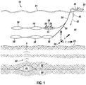
- Fig. 1 depicts an embodiment 10 of a marine seismic data acquisition system in accordance with some embodiments of the invention.
- a survey vessel 20 tows one or more seismic streamers 30 (two exemplary streamers 30 being depicted in Fig. 1 ) behind the vessel 20.
- the seismic streamers 30 may be several thousand meters long and may contain various support cables (not shown), as well as wiring and/or circuitry (not shown) that may be used to support communication along the streamers 30.
- each streamer 30 includes a primary cable into which is mounted seismic sensors that record seismic signals.
- the seismic sensors are multicomponent seismic sensors 58, each of which is capable of detecting a pressure wavefield and at least one component ot a particle motion that is associated with acoustic signals that are proximate to the multi-component seismic sensor 58.
- particle motions include one or more components of a particle displacement, one or more components (inline (x), crossline (y) and vertical (z) components (see axes 59, for example)) of a particle velocity and one or more components of a particle acceleration.
- the multi-component seismic sensor 58 may include one or more hydrophones, geophones, particle displacement sensors, particle velocity sensors, accelerometers, pressure gradient sensors, or combinations thereof.
- a particular multi-component seismic sensor 58 may include a hydrophone 55 for measuring pressure and three orthogonally-aligned accelerometers 50 to measure three corresponding orthogonal components of particle velocity and/or acceleration near the seismic sensor 58. It is noted that the multi-component seismic sensor 58 may be implemented as a single device (as depicted in Fig. 1 ) or may be implemented as a plurality of devices, depending on the particular embodiment of the invention. A particular multi-component seismic sensor 58 may also include pressure gradient sensors 56, which constitute another type of particle motion sensors. Each pressure gradient sensor measures the change in the pressure wavefield at a particular point with respect to a particular direction.
- one of the pressure gradient sensors 56 may acquire seismic data indicative of, at a particular point, the partial derivative of the pressure wavefield with respect to the crossline direction, and another one of the pressure gradient sensors may acquire, at a particular point, seismic data indicative of the pressure data with respect to the inline direction.
- the marine seismic data acquisition system 10 includes one or more seismic sources 40 (one exemplary source 40 being depicted in Fig. 1 ), such as air guns and the like.
- the seismic sources 40 may be coupled to, or towed by, the survey vessel 20.
- the seismic sources 40 may operate independently of the survey vessel 20, in that the sources 40 may be coupled to other vessels or buoys, as just a few examples.
- acoustic signals 42 (an exemplary acoustic signal 42 being depicted in Fig. 1 ), often referred to as "shots," are produced by the seismic sources 40 and are directed down through a water column 44 into strata 62 and 68 beneath a water bottom surface 24.
- the acoustic signals 42 are reflected from the various subterranean geological formations, such as an exemplary formation 65 that is depicted in Fig. 1 .
- the incident acoustic signals 42 that are acquired by the sources 40 produce corresponding reflected acoustic signals, or pressure waves 60, which are sensed by the multi-component seismic sensors 58.
- the pressure waves that are received and sensed by the multi-component seismic sensors 58 include "up going" pressure waves that propagate to the sensors 58 without reflection, as well as “down going” pressure waves that are produced by reflections of the pressure waves 60 from an air-water boundary 31.
- the multi-component seismic sensors 58 generate signals (digital signals, for example), called "traces," which indicate the acquired measurements of the pressure wavefield and particle motion.
- the traces are recorded and may be at least partially processed by a signal processing unit 23 that is deployed on the survey vessel 20, in accordance with some embodiments of the invention.
- a particular multi-component seismic sensor 58 may provide a trace, which corresponds to a measure of a pressure wavefield by its hydrophone 55; and the sensor 58 may provide one or more traces that correspond to one or more components of particle motion, which are measured by its accelerometers 50.
- the goal of the seismic acquisition is to build up an image of a survey area for purposes of identifying subterranean geological formations, such as the exemplary geological formation 65.
- Subsequent analysis of the representation may reveal probable locations of hydrocarbon deposits in subterranean geological formations.
- portions of the analysis of the representation may be performed on the seismic survey vessel 20, such as by the signal processing unit 23.
- the representation may be processed by a seismic data processing system (such as an exemplary seismic data processing system 320 that is depicted in Fig. 4 and is further described below) that may be, for example, located on land or on the vessel 20.
- a seismic data processing system such as an exemplary seismic data processing system 320 that is depicted in Fig. 4 and is further described below
- the down going pressure waves create an interference known as "ghost" in the art.
- the interference between the up going and down going wavefields creates nulls, or notches, in the recorded spectrum. These notches may reduce the useful bandwidth of the spectrum and may limit the possibility of towing the streamers 30 in relatively deep water (water greater than 20 meters (m), tor example).
- the technique of decomposing the recorded wavefield into up and down going components is often referred to as wavefield separation, or "deghosting.”
- deghosting The particle motion data that are provided by the multi-component seismic sensors 58 allows the recovery of "ghost" free data, which means data that are indicative of the upgoing wavefield.
- Deghosted and interpolated seismic data typically are essential for many important seismic data processing tasks, such as imaging, multiple attenuation, time-lapse seismic processing, etc.
- techniques are described that provide for concurrent, or joint, interpolation and deghosting of the acquired seismic data.
- the seismic data are obtained by the regular or irregular sampling of the pressure and particle motion data.
- these data may be sampled along one or more streamers in the marine environment or may be sampled by seismic sensors located on the sea bed, as another example.
- an upgoing component of the pressure wavefield (herein called " p u (x, y; z s , f )" is determined at the seismic sensor locations, as well as at locations other than the sensor locations, without first interpolating the acquired seismic data and then deghosting the interpolated data (or vice versa).
- k x,j represents the inline wavenumber for index j
- k y,j represents the crossline wavenumber for index j
- z s represents the streamer tow depth
- f represents the temporal frequency of the sinusoids
- c represents the acoustic velocity in water.
- the measurements of the vector m p ( x,y ; z s ,f ) are contiguous.
- z s f
- the A j parameters may be determined for purposes of jointly interpolating the acquired seismic data and determining the upgoing pressure component p u ( x,y;z s , f ) .
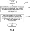
- a technique 120 to generate an upgoing component of a seismic data wavefield includes representing (block 124) actual measurements of a seismic wavefield as combinations of an upgoing component of the seismic wavefield and ghost operators.
- the interpolated and deghosted components of the seismic wavefield are determined based at least in part on the actual measurements and the representation, pursuant to block 128.
- Eqs. 1 and 3 define the upgoing pressure component p u ( x,y ; z s , f ) and measurement vector m P ( x,y ; z s ,f ) as a combination of sinusoidal basis functions.
- the component p u ( x,y;z s ,f ) and the measurement vector m P ( x,y;z s ,f ) may be represented as a combination of other types of basis functions, in accordance with other embodiments of the invention.
- the matching pursuit technique is generally described in S. Mallat and Z. Zhang Mallat "Matching pursuits with time-frequency dictionaries" IEEE Transactions on Signal Processing, vol. 41, no. 12, pp. 3397-3415 (1993 ).
- the matching pursuit algorithm may be regarded as an iterative algorithm, which expands a particular signal in terms of a linear combination of basis functions.
- the matching pursuit algorithm is generalized to the cases where the signal is represented as a linear combination of basis functions that are subject to some linear transformation, e.g., the ghosting operation. This generalized technique described herein is referred to as the Generalized Matching Pursuit (GMP) algorithm.
- GMP Generalized Matching Pursuit
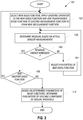
- a technique 150 may be used for purposes of determining the coefficients of Eqs. 1 and 3.
- the technique 150 includes, pursuant to block 152, selecting a new basis function, applying the ghosting operator H ( k x ,k y ; z s ,f ) to the new basis function and adding the transformed basis function to an existing measurement function to form a new measurement function.
- the first basis function (which may be in the simplest form a single sinusoidal function or even a constant) is added, a new exponential is added at every iteration to the set of basis functions used, and the corresponding "ghosted" basis function is added to the representation; and then, an error, or residual, is determined based on the actual seismic data that are acquired by the sensor measurements, pursuant to block 156.
- the residual energy is then minimized for purposes of determining the A j parameters for the new basis function. More specifically, a determination is made (diamond 160) whether the residual energy has been minimized with the current parameters for the new basis function. If not, the parameters are adjusted and the residual energy is again determined, pursuant to block 156. Thus, a loop is formed for purposes of minimizing some metric of the residual energy until a minimum value is determined, which permits the coefficients for the next basis function to be determined. Therefore, pursuant to diamond 168, it another basis function is to be added (based on a predetermined limit ot basis functions, for example), the technique 150 continues with block 152 to add the next basis function and calculate the corresponding parameters. Otherwise, if no more basis functions are to be added, the upgoing component of the seismic event is determined, pursuant to block 174.
- M A ⁇ p k ⁇ x , p k ⁇ y , p z s f ⁇ m , n r A ⁇ p k ⁇ x , P k ⁇ y , P P x y z s f H C ⁇ 1 r A ⁇ P k ⁇ x , P k ⁇ y , P P x y z s f , where "C” represents a four by four positive definite matrix; "x m " represents the sensor locations in the inline direction; and "y n " represents the sensor locations in the crossline direction.
- a seismic data processing system 320 may perform at least some of the techniques that are disclosed herein for purposes of jointly interpolating and deghosting seismic data.
- the system 320 may include a processor 350, such as one or more microprocessors and/or microcontrollers.
- the processor 350 may be located on a streamer 30 ( Fig. 1 ), located on the vessel 20 or located at a land-based processing facility (as examples), depending on the particular embodiment of the invention.
- the processor 350 may be coupled to a communication interface 360 for purposes of receiving seismic data that corresponds to pressure and/or particle motion measurements.
- the processor 350 when executing instructions stored in a memory of the seismic data processing system 320, may receive multi-component data that is acquired by multi-component seismic sensors while in tow.
- the multi-component data may be data that is directly received from the multi-component seismic sensor as the data is being acquired (for the case in which the processor 350 is part of the survey system, such as part of the vessel or streamer) or may be multi-component data that was previously acquired by the seismic sensors while m tow and stored and communicated to the processor 350, which may be in a land-based facility, for example.
- the interface 360 may be a USB serial bus interface, a network interface, a removable media (such as a flash card, CD-ROM, etc.) interface or a magnetic storage interface (IDE or SCSI interfaces, as examples).
- the interface 360 may take on numerous forms, depending on the particular embodiment of the invention.
- the interface 360 may be coupled to a memory 340 of the seismic data processing system 320 and may store, for example, various input and/or output data sets involved with the techniques 120 and/or 150, as indicated by reference numeral 348.
- the memory 340 may store program instructions 344, which when executed by the processor 350, may cause the processor 350 to perform one or more of the techniques that are disclosed herein, such as the techniques 120 and/or 150 and display results obtained via the technique(s) on a display (not shown in Fig. 4 ) of the system 320, in accordance with some embodiments of the invention.
- the seismic data may be acquired using another type of seismic acquisition platform, such as a set of ocean bottom cables, as a nonlimiting example.
- the measurements that are obtained may be irregularly or regularly sampled with respect to space and/or time. Additionally, the techniques that are described herein may be used to determine a downgoing pressure or particle motion component. Additionally, the techniques that are described herein may be used with a subset of particle motion measurements (i.e., measurements in less than all three dimensions). For example, in accordance with some embodiments of the invention, interpolation may be performed in the cross-line direction and the seismic data may be deghosted when only pressure and the "vertical" component of the particle velocity are measured. As another example, the seismic data may be interpolated and deghosted when pressure, the "vertical" component of the particle velocity and the "crossline” component of the particle velocity are used. These variations are contemplated and are within the scope of the appended claims.
- the measurement function may be represented as multiple signals, where each signal is associated with a different frequency band.
- the signal tor each frequency band may be separately, or independently, interpolated.
- different spatial bandwidths may be used in the different frequency bands for the representation of the upgoing wavefield by the combined basis functions. It is noted that the different spatial bandwidths may be determined by the speed of propagation of the signals.
Description
- The invention generally relates to jointly interpolating and deghosting seismic data.
- Seismic exploration involves surveying subterranean geological formations for hydrocarbon deposits. A survey typically involves deploying seismic source(s) and seismic sensors at predetermined locations. The sources generate seismic waves, which propagate into the geological formations creating pressure changes and vibrations along their way. Changes in elastic properties of the geological formation scatter the seismic waves, changing their direction of propagation and other properties. Part of the energy emitted by the sources reaches the seismic sensors. Some seismic sensors are sensitive to pressure changes (hydrophones), others to particle motion (e.g., geophones), and industrial surveys may deploy only one type of sensors or both. In response to the detected seismic events, the sensors generate electrical signals to produce seismic data. Analysis of the seismic data can then indicate the presence or absence of probable locations of hydrocarbon deposits.
- Some surveys are known as "marine" surveys because they are conducted in marine environments. However, "marine" surveys may be conducted not only in saltwater environments, but also in fresh and brackish waters. In one type of marine survey, called a "towed-array" survey, an array of seismic sensor-containing streamers and sources is towed behind a survey vessel.
- [
GB 2405473 - The present invention resides in a computer-implemented method, a system and an article as defined in the appended claims.
- Advantages and other features of the invention will become apparent from the following drawing, description and claims.
-
-
Fig. 1 is a schematic diagram of a marine acquisition system according to an embodiment of the invention. -
Figs. 2 and3 are flow diagrams depicting techniques to jointly interpolate and deghost seismic data according to embodiments of the invention. -
Fig. 4 is a schematic diagram of a schematic data processing system according to an embodiment of the invention. -
Fig. 1 depicts anembodiment 10 of a marine seismic data acquisition system in accordance with some embodiments of the invention. In thesystem 10, asurvey vessel 20 tows one or more seismic streamers 30 (twoexemplary streamers 30 being depicted inFig. 1 ) behind thevessel 20. Theseismic streamers 30 may be several thousand meters long and may contain various support cables (not shown), as well as wiring and/or circuitry (not shown) that may be used to support communication along thestreamers 30. In general, eachstreamer 30 includes a primary cable into which is mounted seismic sensors that record seismic signals. - In accordance with embodiments of the invention, the seismic sensors are multicomponent
seismic sensors 58, each of which is capable of detecting a pressure wavefield and at least one component ot a particle motion that is associated with acoustic signals that are proximate to the multi-componentseismic sensor 58. Examples of particle motions include one or more components of a particle displacement, one or more components (inline (x), crossline (y) and vertical (z) components (seeaxes 59, for example)) of a particle velocity and one or more components of a particle acceleration. - Depending on the particular embodiment of the invention, the multi-component
seismic sensor 58 may include one or more hydrophones, geophones, particle displacement sensors, particle velocity sensors, accelerometers, pressure gradient sensors, or combinations thereof. - For example, in accordance with some embodiments of the invention, a particular multi-component
seismic sensor 58 may include ahydrophone 55 for measuring pressure and three orthogonally-alignedaccelerometers 50 to measure three corresponding orthogonal components of particle velocity and/or acceleration near theseismic sensor 58. It is noted that the multi-componentseismic sensor 58 may be implemented as a single device (as depicted inFig. 1 ) or may be implemented as a plurality of devices, depending on the particular embodiment of the invention. A particular multi-componentseismic sensor 58 may also includepressure gradient sensors 56, which constitute another type of particle motion sensors. Each pressure gradient sensor measures the change in the pressure wavefield at a particular point with respect to a particular direction. For example, one of thepressure gradient sensors 56 may acquire seismic data indicative of, at a particular point, the partial derivative of the pressure wavefield with respect to the crossline direction, and another one of the pressure gradient sensors may acquire, at a particular point, seismic data indicative of the pressure data with respect to the inline direction. - The marine seismic
data acquisition system 10 includes one or more seismic sources 40 (oneexemplary source 40 being depicted inFig. 1 ), such as air guns and the like. In some embodiments of the invention, theseismic sources 40 may be coupled to, or towed by, thesurvey vessel 20. Alternatively, in other embodiments of the invention, theseismic sources 40 may operate independently of thesurvey vessel 20, in that thesources 40 may be coupled to other vessels or buoys, as just a few examples. - As the
seismic streamers 30 are towed behind thesurvey vessel 20, acoustic signals 42 (an exemplaryacoustic signal 42 being depicted inFig. 1 ), often referred to as "shots," are produced by theseismic sources 40 and are directed down through awater column 44 intostrata water bottom surface 24. Theacoustic signals 42 are reflected from the various subterranean geological formations, such as anexemplary formation 65 that is depicted inFig. 1 . - The incident
acoustic signals 42 that are acquired by thesources 40 produce corresponding reflected acoustic signals, orpressure waves 60, which are sensed by the multi-componentseismic sensors 58. It is noted that the pressure waves that are received and sensed by the multi-componentseismic sensors 58 include "up going" pressure waves that propagate to thesensors 58 without reflection, as well as "down going" pressure waves that are produced by reflections of thepressure waves 60 from an air-water boundary 31. - The multi-component
seismic sensors 58 generate signals (digital signals, for example), called "traces," which indicate the acquired measurements of the pressure wavefield and particle motion. The traces are recorded and may be at least partially processed by asignal processing unit 23 that is deployed on thesurvey vessel 20, in accordance with some embodiments of the invention. For example, a particular multi-componentseismic sensor 58 may provide a trace, which corresponds to a measure of a pressure wavefield by itshydrophone 55; and thesensor 58 may provide one or more traces that correspond to one or more components of particle motion, which are measured by itsaccelerometers 50. - The goal of the seismic acquisition is to build up an image of a survey area for purposes of identifying subterranean geological formations, such as the exemplary
geological formation 65. Subsequent analysis of the representation may reveal probable locations of hydrocarbon deposits in subterranean geological formations. Depending on the particular embodiment of the invention, portions of the analysis of the representation may be performed on theseismic survey vessel 20, such as by thesignal processing unit 23. In accordance with other embodiments of the invention, the representation may be processed by a seismic data processing system (such as an exemplary seismicdata processing system 320 that is depicted inFig. 4 and is further described below) that may be, for example, located on land or on thevessel 20. Thus, many variations are possible and are within the scope of the appended claims. - The down going pressure waves create an interference known as "ghost" in the art. Depending on the incidence angle of the up going wavefield and the depth of the
streamer 30, the interference between the up going and down going wavefields creates nulls, or notches, in the recorded spectrum. These notches may reduce the useful bandwidth of the spectrum and may limit the possibility of towing thestreamers 30 in relatively deep water (water greater than 20 meters (m), tor example). - The technique of decomposing the recorded wavefield into up and down going components is often referred to as wavefield separation, or "deghosting." The particle motion data that are provided by the multi-component
seismic sensors 58 allows the recovery of "ghost" free data, which means data that are indicative of the upgoing wavefield. - Deghosted and interpolated seismic data typically are essential for many important seismic data processing tasks, such as imaging, multiple attenuation, time-lapse seismic processing, etc. In accordance with embodiments of the invention described herein, techniques are described that provide for concurrent, or joint, interpolation and deghosting of the acquired seismic data. More specifically, the seismic data are obtained by the regular or irregular sampling of the pressure and particle motion data. As an example, these data may be sampled along one or more streamers in the marine environment or may be sampled by seismic sensors located on the sea bed, as another example.
- Techniques and systems are described herein that jointly interpolate and deghost acquired seismic data. More specifically, based on the measurements that are acquired by the multi-component sensors, an upgoing component of the pressure wavefield (herein called " pu(x, y; zs, f)") component is determined at the seismic sensor locations, as well as at locations other than the sensor locations, without first interpolating the acquired seismic data and then deghosting the interpolated data (or vice versa).
- The upgoing pressure wave component pu (x,y;zs,f) at a temporal frequency f and cable depth zs may, in general, be modeled as a continuous signal as the sum of J sinusoids that have complex amplitudes (called "Aj,"), as set forth below:

- In Eq. 1, "kx,j" represents the inline wavenumber for index j; "ky,j" represents the crossline wavenumber for index j; "zs" represents the streamer tow depth; "f" represents the temporal frequency of the sinusoids; and "c" represents the acoustic velocity in water. Additionally, "kz,j," the wavenumber in the vertical, or depth, direction may be described as follows:

- Based on the representation of the upgomg pressure component pu (x,y;zs,f) in Eq. 3, the pressure and particle motion measurements may be represented as continuous signals described below:

- The measurement vector mP (x,y;zs,f) may be described as follows:


- Due to the relationships set forth in Eqs. 1 and 3, the Aj parameters may be determined for purposes of jointly interpolating the acquired seismic data and determining the upgoing pressure component pu (x,y;zs ,f).
- More specifically, referring to
Fig. 2 , in accordance with some embodiments of the invention, atechnique 120 to generate an upgoing component of a seismic data wavefield, such as an upgoing pressure component, includes representing (block 124) actual measurements of a seismic wavefield as combinations of an upgoing component of the seismic wavefield and ghost operators. Pursuant to thetechnique 120, the interpolated and deghosted components of the seismic wavefield are determined based at least in part on the actual measurements and the representation, pursuant to block 128. - Eqs. 1 and 3 define the upgoing pressure component pu (x,y;zs ,f) and measurement vector mP (x,y;zs,f) as a combination of sinusoidal basis functions. However, it is noted that the component pu (x,y;zs,f) and the measurement vector mP (x,y;zs,f) may be represented as a combination of other types of basis functions, in accordance with other embodiments of the invention.
- If the sinusoids in Eq. 3 were not subject to the ghosting operators, then a matching pursuit technique could be used to identify the parameters of the sinusoids. The matching pursuit technique is generally described in S. Mallat and Z. Zhang Mallat "Matching pursuits with time-frequency dictionaries" IEEE Transactions on Signal Processing, vol. 41, no. 12, pp. 3397-3415 (1993). The matching pursuit algorithm may be regarded as an iterative algorithm, which expands a particular signal in terms of a linear combination of basis functions. As described herein, the matching pursuit algorithm is generalized to the cases where the signal is represented as a linear combination of basis functions that are subject to some linear transformation, e.g., the ghosting operation. This generalized technique described herein is referred to as the Generalized Matching Pursuit (GMP) algorithm.
- Referring to
Fig. 3 , in accordance with some embodiments of the invention, atechnique 150 may be used for purposes of determining the coefficients of Eqs. 1 and 3. In this regard, thetechnique 150 includes, pursuant to block 152, selecting a new basis function, applying the ghosting operator H(kx,ky ;zs,f) to the new basis function and adding the transformed basis function to an existing measurement function to form a new measurement function. In this regard, after the first basis function (which may be in the simplest form a single sinusoidal function or even a constant) is added, a new exponential is added at every iteration to the set of basis functions used, and the corresponding "ghosted" basis function is added to the representation; and then, an error, or residual, is determined based on the actual seismic data that are acquired by the sensor measurements, pursuant to block 156. - The residual energy is then minimized for purposes of determining the Aj parameters for the new basis function. More specifically, a determination is made (diamond 160) whether the residual energy has been minimized with the current parameters for the new basis function. If not, the parameters are adjusted and the residual energy is again determined, pursuant to block 156. Thus, a loop is formed for purposes of minimizing some metric of the residual energy until a minimum value is determined, which permits the coefficients for the next basis function to be determined. Therefore, pursuant to
diamond 168, it another basis function is to be added (based on a predetermined limit ot basis functions, for example), thetechnique 150 continues withblock 152 to add the next basis function and calculate the corresponding parameters. Otherwise, if no more basis functions are to be added, the upgoing component of the seismic event is determined, pursuant to block 174. - As a more specific example, the Aj parameters for the newest basis function may be determined by minimizing the energy of the residual. Therefore, if P-1 basis functions have been determined previously, the representation of the component pu (x,y;zs,f) with the P-1 sinusoids may be as follows:

- The corresponding measurement function for the P-1 basis functions may be obtained by applying the ghost operators to the basis functions:

- The residual in the approximation, called "r P-1(x,y;zs,f)" may be defined as follows:

- If a new basis function "
A Pe j2π(kx,jy+kz,jzs )," which has a corresponding coefficient called "A P" is added to the existing representation of the upgoing wavefield, then the residual may be rewritten as follows:
- It is noted that for Eq. 9, the parameters AP, kx,P, ky,P for the new basis function term are determined.
- As a specific example, the parameters of the new basis function may be found by minimizing some metric of the residual, which is calculated over inline and crossline sensor locations, as described below:

- One such example metric may be described as follows:

- Referring to
Fig. 4 , in accordance with some embodiments of the invention, a seismicdata processing system 320 may perform at least some of the techniques that are disclosed herein for purposes of jointly interpolating and deghosting seismic data. In accordance with some embodiments of the invention, thesystem 320 may include aprocessor 350, such as one or more microprocessors and/or microcontrollers. Theprocessor 350 may be located on a streamer 30 (Fig. 1 ), located on thevessel 20 or located at a land-based processing facility (as examples), depending on the particular embodiment of the invention. - The
processor 350 may be coupled to acommunication interface 360 for purposes of receiving seismic data that corresponds to pressure and/or particle motion measurements. Thus, in accordance with embodiments of the invention described herein, theprocessor 350, when executing instructions stored in a memory of the seismicdata processing system 320, may receive multi-component data that is acquired by multi-component seismic sensors while in tow. It is noted that, depending on the particular embodiment of the invention, the multi-component data may be data that is directly received from the multi-component seismic sensor as the data is being acquired (for the case in which theprocessor 350 is part of the survey system, such as part of the vessel or streamer) or may be multi-component data that was previously acquired by the seismic sensors while m tow and stored and communicated to theprocessor 350, which may be in a land-based facility, for example. - As examples, the
interface 360 may be a USB serial bus interface, a network interface, a removable media (such as a flash card, CD-ROM, etc.) interface or a magnetic storage interface (IDE or SCSI interfaces, as examples). Thus, theinterface 360 may take on numerous forms, depending on the particular embodiment of the invention. - In accordance with some embodiments of the invention, the
interface 360 may be coupled to amemory 340 of the seismicdata processing system 320 and may store, for example, various input and/or output data sets involved with thetechniques 120 and/or 150, as indicated byreference numeral 348. Thememory 340 may storeprogram instructions 344, which when executed by theprocessor 350, may cause theprocessor 350 to perform one or more of the techniques that are disclosed herein, such as thetechniques 120 and/or 150 and display results obtained via the technique(s) on a display (not shown inFig. 4 ) of thesystem 320, in accordance with some embodiments of the invention. - Other embodiments are within the scope of the appended claims. For example, in other embodiments of the invention, the seismic data may be acquired using another type of seismic acquisition platform, such as a set of ocean bottom cables, as a nonlimiting example.
- As additional examples of other embodiments of the invention, the measurements that are obtained may be irregularly or regularly sampled with respect to space and/or time. Additionally, the techniques that are described herein may be used to determine a downgoing pressure or particle motion component. Additionally, the techniques that are described herein may be used with a subset of particle motion measurements (i.e., measurements in less than all three dimensions). For example, in accordance with some embodiments of the invention, interpolation may be performed in the cross-line direction and the seismic data may be deghosted when only pressure and the "vertical" component of the particle velocity are measured. As another example, the seismic data may be interpolated and deghosted when pressure, the "vertical" component of the particle velocity and the "crossline" component of the particle velocity are used. These variations are contemplated and are within the scope of the appended claims.
- As another variation, in accordance with some embodiments of the invention, the measurement function may be represented as multiple signals, where each signal is associated with a different frequency band. In this regard, the signal tor each frequency band may be separately, or independently, interpolated. Additionally, different spatial bandwidths may be used in the different frequency bands for the representation of the upgoing wavefield by the combined basis functions. It is noted that the different spatial bandwidths may be determined by the speed of propagation of the signals.
Claims (12)
- A computer-implemented method comprising:representing actual measurements of a seismic wavefield as combinations of an upgoing pressure component of the seismic wavefield and ghost operators, wherein the act of representing comprises representing the upgoing pressure component as a linear combination of basis functions; anddetermining the coefficients of the linear combination of basis functions, thereby jointly determining interpolated and deghosted components of the seismic wavefield, based at least in part on the actual measurements and the representation, wherein the act of determining comprises:determining coefficients of the linear combination of basis functions in an iterative sequence of adding a basis function to the existing linear combination of basis functions, applying the ghost operator to the added basis function to generate a transformed basis function;adding the transformed basis function to an existing representation of the actual measurements to generate a new representation of the actual measurements; andminimizing a residual between the actual measurements and the new representation of the actual measurements; andbuilding up an image of a survey area based on the interpolated and deghosted seismic data for the purposes of identifying subterranean geological formations.
- The method of claim 1, wherein the act of determining comprises determining coefficients of the linear combination of the basis functions using a generalized matching pursuit technique.
- The method of claim 1, wherein the act of jointly determining comprises determining an upgoing component or a downgoing component of a pressure or of a particle motion.
- The method of claim 1, wherein the ghost operator comprises an operator that is a function of at least one of an acoustic velocity, a streamer depth and a sea surface reflection coefficient.
- The method of claim 1, wherein the actual measurements comprise a vector of pressure and particle motion measurements.
- The method of claim 5, wherein the actual measurement vector comprises the three particle motion components in addition to the pressure component or wherein the actual measurement vector comprises any subset of pressure and particle motion components.
- The method of claim 1, wherein the actual measurements comprise one of:a) measurements acquired by a spread of towed streamers;b) measurements acquired by a spread of over/under streamers or a set of ocean bottom cables;c) measurements acquired at regularly or irregularly spaced positions and/or times; ord) measurements in a three-dimensional space.
- The method of claim 1, wherein the act of determining comprises: representing the measurements as signals associated with a plurality of frequency bands; and
determining the signals independently. - The method of claim 8, wherein the act of determining further comprises:
using different spatial bandwidths in the different frequency bands for the representation of an upgoing wavefield by combining basis functions. - The method of claim 9, wherein the different spatial bandwidths are based on the speed of propagation of the signals.
- A system comprising:an interface to receive actual measurements of a seismic wavefield acquired by seismic sensors; anda processor to process the seismic data according to a method as defined in any one of claims 1-10.
- An article comprising instructions stored on a computer accessible storage medium that when executed by a processor-based system cause the processor-based system to perform a method as defined in any one of claims 1-10.
Applications Claiming Priority (2)
| Application Number | Priority Date | Filing Date | Title |
|---|---|---|---|
| US12/131,870 US7817495B2 (en) | 2008-06-02 | 2008-06-02 | Jointly interpolating and deghosting seismic data |
| PCT/US2009/045240 WO2010044918A2 (en) | 2008-06-02 | 2009-05-27 | Jointly interpolating and deghosting seismic data |
Publications (3)
| Publication Number | Publication Date |
|---|---|
| EP2283385A2 EP2283385A2 (en) | 2011-02-16 |
| EP2283385A4 EP2283385A4 (en) | 2013-10-16 |
| EP2283385B1 true EP2283385B1 (en) | 2019-10-23 |
Family
ID=41379636
Family Applications (1)
| Application Number | Title | Priority Date | Filing Date |
|---|---|---|---|
| EP09820930.7A Active EP2283385B1 (en) | 2008-06-02 | 2009-05-27 | Jointly interpolating and deghosting seismic data |
Country Status (8)
| Country | Link |
|---|---|
| US (2) | US7817495B2 (en) |
| EP (1) | EP2283385B1 (en) |
| CN (1) | CN102027390B (en) |
| AU (1) | AU2009303787B2 (en) |
| BR (1) | BRPI0913227B1 (en) |
| MX (1) | MX2010012702A (en) |
| RU (1) | RU2507543C2 (en) |
| WO (1) | WO2010044918A2 (en) |
Families Citing this family (40)
| Publication number | Priority date | Publication date | Assignee | Title |
|---|---|---|---|---|
| GB0724847D0 (en) | 2007-12-20 | 2008-01-30 | Statoilhydro | Method of and apparatus for exploring a region below a surface of the earth |
| US7817495B2 (en) * | 2008-06-02 | 2010-10-19 | Westerngeco L.L.C. | Jointly interpolating and deghosting seismic data |
| US8699297B2 (en) * | 2009-02-13 | 2014-04-15 | Westerngeco L.L.C. | Deghosting and reconstructing a seismic wavefield |
| US8554484B2 (en) * | 2009-02-13 | 2013-10-08 | Westerngeco L.L.C. | Reconstructing seismic wavefields |
| US20100211320A1 (en) * | 2009-02-13 | 2010-08-19 | Massimiliano Vassallo | Reconstructing a seismic wavefield |
| US10545252B2 (en) * | 2010-01-15 | 2020-01-28 | Westerngeco L.L.C. | Deghosting and interpolating seismic data |
| JP5574724B2 (en) * | 2010-01-27 | 2014-08-20 | キヤノン株式会社 | Subject information processing apparatus and subject information processing method |
| GB2479200A (en) | 2010-04-01 | 2011-10-05 | Statoil Asa | Interpolating pressure and/or vertical particle velocity data from multi-component marine seismic data including horizontal derivatives |
| US8757270B2 (en) | 2010-05-28 | 2014-06-24 | Statoil Petroleum As | Subsea hydrocarbon production system |
| US9043155B2 (en) * | 2010-10-07 | 2015-05-26 | Westerngeco L.L.C. | Matching pursuit-based apparatus and technique to construct a seismic signal using a predicted energy distribution |
| US20120147700A1 (en) * | 2010-12-14 | 2012-06-14 | Svein Arne Frivik | Determining Streamer Depth and Sea Surface Profile |
| US20140043934A1 (en) * | 2011-05-24 | 2014-02-13 | Westerngeco L.L.C. | Data acquisition |
| US10459099B2 (en) * | 2011-09-22 | 2019-10-29 | Cgg Services Sas | Device and method to determine shape of streamer |
| US8862408B2 (en) | 2011-09-28 | 2014-10-14 | Westerngeco L.L.C. | Determining one or more target positions in an acquisition domain for processing survey data |
| US20130088939A1 (en) * | 2011-10-10 | 2013-04-11 | Pascal Edme | Wavefield separation using a gradient sensor |
| US9541659B2 (en) * | 2011-11-18 | 2017-01-10 | Westerngeco L.L.C. | Noise removal from 3D seismic representation |
| US9103943B2 (en) | 2011-11-28 | 2015-08-11 | Fugro-Geoteam As | Acquisition and processing of multi-source broadband marine seismic data |
| US9176249B2 (en) | 2011-12-21 | 2015-11-03 | Cggveritas Services Sa | Device and method for processing variable depth streamer data |
| US9103941B2 (en) * | 2011-12-21 | 2015-08-11 | Cggveritas Services Sa | Device and method for deghosting variable depth streamer data |
| US9405027B2 (en) | 2012-01-12 | 2016-08-02 | Westerngeco L.L.C. | Attentuating noise acquired in an energy measurement |
| US9274239B2 (en) * | 2012-01-13 | 2016-03-01 | Westerngeco L.L.C. | Wavefield deghosting |
| US9671511B2 (en) | 2012-08-31 | 2017-06-06 | Cgg Services Sas | Horizontal streamer broadband marine seismic acquisition configuration and processing |
| US20140200812A1 (en) * | 2013-01-11 | 2014-07-17 | Westerngeco L.L.C. | Processing survey data for determining a wavefield |
| US9405028B2 (en) | 2013-02-22 | 2016-08-02 | Ion Geophysical Corporation | Method and apparatus for multi-component datuming |
| US20160139283A1 (en) * | 2013-06-25 | 2016-05-19 | Westerngeco L.L.C. | Seismic wavefield deghosting and noise attenuation |
| WO2015104637A2 (en) * | 2014-01-13 | 2015-07-16 | Cgg Services Sa | Device and method for deghosting seismic data using sparse tau-p inversion |
| EP3137926A4 (en) | 2014-04-28 | 2017-12-13 | Westerngeco LLC | Wavefield reconstruction |
| MX2017000132A (en) | 2014-07-01 | 2017-04-27 | Pgs Geophysical As | Wavefield reconstruction. |
| US10422898B2 (en) | 2014-09-23 | 2019-09-24 | Westerngeco L.L.C. | Seismic data processing |
| AU2015335648A1 (en) * | 2014-10-24 | 2017-04-27 | Schlumberger Technology B.V. | Joint interpolation and deghosting of seismic data |
| CA3198537A1 (en) | 2015-05-01 | 2016-11-10 | Reflection Marine Norge As | Marine vibrator directive source survey |
| US10996359B2 (en) | 2015-05-05 | 2021-05-04 | Schlumberger Technology Corporation | Removal of acquisition effects from marine seismic data |
| CA3006953A1 (en) | 2015-12-02 | 2017-06-08 | Schlumberger Canada Limited | Land seismic sensor spread with adjacent multicomponent seismic sensor pairs on average at least twenty meters apart |
| CA3018757A1 (en) | 2016-03-24 | 2017-09-28 | Saudi Arabian Oil Company | Simultaneous wavefield reconstruction and receiver deghosting of seismic streamer data using an l1 inversion |
| US20170363756A1 (en) | 2016-06-15 | 2017-12-21 | Schlumerger Technology Corporation | Systems and methods for acquiring seismic data with gradient data |
| US10871586B2 (en) | 2017-05-17 | 2020-12-22 | Cgg Services Sas | Device and method for multi-shot wavefield reconstruction |
| CN107390272B (en) * | 2017-07-10 | 2019-09-13 | 中国海洋石油集团有限公司 | A kind of seismic receiver system |
| US10996361B2 (en) | 2018-09-07 | 2021-05-04 | Saudi Arabian Oil Company | Adaptive receiver deghosting for seismic streamer |
| US11650343B2 (en) * | 2019-04-17 | 2023-05-16 | Pgs Geophysical As | Directional designature of marine seismic survey data |
| US11320557B2 (en) | 2020-03-30 | 2022-05-03 | Saudi Arabian Oil Company | Post-stack time domain image with broadened spectrum |
Citations (1)
| Publication number | Priority date | Publication date | Assignee | Title |
|---|---|---|---|---|
| GB2405473A (en) * | 2003-08-23 | 2005-03-02 | Westerngeco Ltd | Multiple attenuation in marine seismic survey |
Family Cites Families (18)
| Publication number | Priority date | Publication date | Assignee | Title |
|---|---|---|---|---|
| SU873185A1 (en) * | 1980-02-27 | 1981-10-15 | Всесоюзный Научно-Исследовательский Институт Ядерной Геофизики И Геохимии | Method of oil and gas deposit prospecting |
| US5850622A (en) * | 1996-11-08 | 1998-12-15 | Amoco Corporation | Time-frequency processing and analysis of seismic data using very short-time fourier transforms |
| US7415401B2 (en) * | 2000-08-31 | 2008-08-19 | Exxonmobil Upstream Research Company | Method for constructing 3-D geologic models by combining multiple frequency passbands |
| CA2431251A1 (en) * | 2000-12-07 | 2002-06-13 | Schlumberger Canada Limited | A method of and apparatus for processing seismic data |
| GB2384053B (en) * | 2002-01-11 | 2005-09-14 | Westerngeco Ltd | A method of and apparatus for processing seismic data |
| GB2389183B (en) * | 2002-05-28 | 2006-07-26 | Westerngeco Ltd | Processing seismic data |
| EP1474705B1 (en) * | 2002-01-14 | 2013-04-24 | WesternGeco Seismic Holdings Limited | Processing seismic data |
| US6704244B1 (en) * | 2002-10-08 | 2004-03-09 | Pgs Americas, Inc. | Method for acquiring and processing seismic survey data using ocean bottom cables and streamers |
| GB2414299B (en) * | 2004-05-21 | 2006-08-09 | Westerngeco Ltd | Interpolation and extrapolation method for seismic recordings |
| GB2415040B (en) * | 2004-06-12 | 2007-03-21 | Westerngeco Ltd | Three-dimensional deghosting |
| US7492665B2 (en) * | 2006-07-24 | 2009-02-17 | Westerngeco L.L.C. | Seismic data acquisition and source-side derivatives generation and application |
| US7835225B2 (en) * | 2006-10-11 | 2010-11-16 | Pgs Geophysical As | Method for attenuating particle motion sensor noise in dual sensor towed marine seismic streamers |
| US7676327B2 (en) | 2007-04-26 | 2010-03-09 | Westerngeco L.L.C. | Method for optimal wave field separation |
| US7715988B2 (en) * | 2007-06-13 | 2010-05-11 | Westerngeco L.L.C. | Interpolating and deghosting multi-component seismic sensor data |
| GB2450122B (en) | 2007-06-13 | 2009-08-05 | Westerngeco Seismic Holdings | Method of representing signals |
| US9279899B2 (en) | 2007-07-18 | 2016-03-08 | Westerngeco L.L.C. | System and technique to estimate physical propagation parameters associated with a seismic survey |
| US8116166B2 (en) * | 2007-09-10 | 2012-02-14 | Westerngeco L.L.C. | 3D deghosting of multicomponent or over / under streamer recordings using cross-line wavenumber spectra of hydrophone data |
| US7817495B2 (en) | 2008-06-02 | 2010-10-19 | Westerngeco L.L.C. | Jointly interpolating and deghosting seismic data |
-
2008
- 2008-06-02 US US12/131,870 patent/US7817495B2/en active Active
-
2009
- 2009-05-27 BR BRPI0913227-9A patent/BRPI0913227B1/en active IP Right Grant
- 2009-05-27 CN CN200980115088.9A patent/CN102027390B/en active Active
- 2009-05-27 MX MX2010012702A patent/MX2010012702A/en active IP Right Grant
- 2009-05-27 EP EP09820930.7A patent/EP2283385B1/en active Active
- 2009-05-27 WO PCT/US2009/045240 patent/WO2010044918A2/en active Application Filing
- 2009-05-27 AU AU2009303787A patent/AU2009303787B2/en active Active
- 2009-05-27 RU RU2010153589/28A patent/RU2507543C2/en active
-
2010
- 2010-09-15 US US12/882,327 patent/US9030910B2/en active Active
Patent Citations (1)
| Publication number | Priority date | Publication date | Assignee | Title |
|---|---|---|---|---|
| GB2405473A (en) * | 2003-08-23 | 2005-03-02 | Westerngeco Ltd | Multiple attenuation in marine seismic survey |
Also Published As
| Publication number | Publication date |
|---|---|
| RU2010153589A (en) | 2012-07-20 |
| WO2010044918A2 (en) | 2010-04-22 |
| US9030910B2 (en) | 2015-05-12 |
| AU2009303787A1 (en) | 2010-04-22 |
| US7817495B2 (en) | 2010-10-19 |
| AU2009303787B2 (en) | 2014-05-15 |
| EP2283385A2 (en) | 2011-02-16 |
| WO2010044918A3 (en) | 2010-07-08 |
| CN102027390B (en) | 2014-09-10 |
| BRPI0913227A2 (en) | 2016-01-19 |
| MX2010012702A (en) | 2010-12-21 |
| RU2507543C2 (en) | 2014-02-20 |
| CN102027390A (en) | 2011-04-20 |
| US20090296523A1 (en) | 2009-12-03 |
| BRPI0913227B1 (en) | 2023-10-10 |
| EP2283385A4 (en) | 2013-10-16 |
| US20110002192A1 (en) | 2011-01-06 |
Similar Documents
| Publication | Publication Date | Title |
|---|---|---|
| EP2283385B1 (en) | Jointly interpolating and deghosting seismic data | |
| US7715988B2 (en) | Interpolating and deghosting multi-component seismic sensor data | |
| US8699297B2 (en) | Deghosting and reconstructing a seismic wavefield | |
| EP2396675B1 (en) | Reconstructing seismic wavefields | |
| US20100211320A1 (en) | Reconstructing a seismic wavefield | |
| US9541659B2 (en) | Noise removal from 3D seismic representation | |
| EP2174166B1 (en) | Method and system to estimate physical propagation parameters associated with a seismic survey | |
| EP2279436B1 (en) | System and technique to determine high order derivatives from seismic sensor data | |
| US20090326895A1 (en) | Technique and system for seismic source separation | |
| US8760967B2 (en) | Generating an angle domain common image gather | |
| US20100211322A1 (en) | Interpolating a pressure wavefield along an undersampled direction | |
| US10545252B2 (en) | Deghosting and interpolating seismic data | |
| AU2011209707B2 (en) | Interpolation and deghosting of seismic data acquired in the presence of a rough sea | |
| AU2014202655B2 (en) | Jointly interpolating and deghosting seismic data | |
| AU2015224508B2 (en) | Deghosting and interpolating seismic data |
Legal Events
| Date | Code | Title | Description |
|---|---|---|---|
| PUAI | Public reference made under article 153(3) epc to a published international application that has entered the european phase |
Free format text: ORIGINAL CODE: 0009012 |
|
| 17P | Request for examination filed |
Effective date: 20101019 |
|
| AK | Designated contracting states |
Kind code of ref document: A2 Designated state(s): AT BE BG CH CY CZ DE DK EE ES FI FR GB GR HR HU IE IS IT LI LT LU LV MC MK MT NL NO PL PT RO SE SI SK TR |
|
| AX | Request for extension of the european patent |
Extension state: AL BA RS |
|
| DAX | Request for extension of the european patent (deleted) | ||
| A4 | Supplementary search report drawn up and despatched |
Effective date: 20130917 |
|
| RIC1 | Information provided on ipc code assigned before grant |
Ipc: G01V 1/38 20060101ALI20130911BHEP Ipc: G01V 1/36 20060101AFI20130911BHEP |
|
| STAA | Information on the status of an ep patent application or granted ep patent |
Free format text: STATUS: EXAMINATION IS IN PROGRESS |
|
| 17Q | First examination report despatched |
Effective date: 20161107 |
|
| GRAP | Despatch of communication of intention to grant a patent |
Free format text: ORIGINAL CODE: EPIDOSNIGR1 |
|
| STAA | Information on the status of an ep patent application or granted ep patent |
Free format text: STATUS: GRANT OF PATENT IS INTENDED |
|
| INTG | Intention to grant announced |
Effective date: 20190524 |
|
| RIN1 | Information on inventor provided before grant (corrected) |
Inventor name: VASSALLO, MASSIMILIANO Inventor name: OZDEMIR, AHMET KEMAL Inventor name: OZBEK, ALI |
|
| GRAS | Grant fee paid |
Free format text: ORIGINAL CODE: EPIDOSNIGR3 |
|
| GRAA | (expected) grant |
Free format text: ORIGINAL CODE: 0009210 |
|
| STAA | Information on the status of an ep patent application or granted ep patent |
Free format text: STATUS: THE PATENT HAS BEEN GRANTED |
|
| AK | Designated contracting states |
Kind code of ref document: B1 Designated state(s): AT BE BG CH CY CZ DE DK EE ES FI FR GB GR HR HU IE IS IT LI LT LU LV MC MK MT NL NO PL PT RO SE SI SK TR |
|
| REG | Reference to a national code |
Ref country code: GB Ref legal event code: FG4D |
|
| REG | Reference to a national code |
Ref country code: CH Ref legal event code: EP |
|
| REG | Reference to a national code |
Ref country code: IE Ref legal event code: FG4D |
|
| REG | Reference to a national code |
Ref country code: DE Ref legal event code: R096 Ref document number: 602009060251 Country of ref document: DE |
|
| REG | Reference to a national code |
Ref country code: AT Ref legal event code: REF Ref document number: 1194284 Country of ref document: AT Kind code of ref document: T Effective date: 20191115 |
|
| REG | Reference to a national code |
Ref country code: NL Ref legal event code: MP Effective date: 20191023 |
|
| REG | Reference to a national code |
Ref country code: LT Ref legal event code: MG4D |
|
| REG | Reference to a national code |
Ref country code: NO Ref legal event code: T2 Effective date: 20191023 |
|
| PG25 | Lapsed in a contracting state [announced via postgrant information from national office to epo] |
Ref country code: PT Free format text: LAPSE BECAUSE OF FAILURE TO SUBMIT A TRANSLATION OF THE DESCRIPTION OR TO PAY THE FEE WITHIN THE PRESCRIBED TIME-LIMIT Effective date: 20200224 Ref country code: FI Free format text: LAPSE BECAUSE OF FAILURE TO SUBMIT A TRANSLATION OF THE DESCRIPTION OR TO PAY THE FEE WITHIN THE PRESCRIBED TIME-LIMIT Effective date: 20191023 Ref country code: NL Free format text: LAPSE BECAUSE OF FAILURE TO SUBMIT A TRANSLATION OF THE DESCRIPTION OR TO PAY THE FEE WITHIN THE PRESCRIBED TIME-LIMIT Effective date: 20191023 Ref country code: PL Free format text: LAPSE BECAUSE OF FAILURE TO SUBMIT A TRANSLATION OF THE DESCRIPTION OR TO PAY THE FEE WITHIN THE PRESCRIBED TIME-LIMIT Effective date: 20191023 Ref country code: SE Free format text: LAPSE BECAUSE OF FAILURE TO SUBMIT A TRANSLATION OF THE DESCRIPTION OR TO PAY THE FEE WITHIN THE PRESCRIBED TIME-LIMIT Effective date: 20191023 Ref country code: LT Free format text: LAPSE BECAUSE OF FAILURE TO SUBMIT A TRANSLATION OF THE DESCRIPTION OR TO PAY THE FEE WITHIN THE PRESCRIBED TIME-LIMIT Effective date: 20191023 Ref country code: BG Free format text: LAPSE BECAUSE OF FAILURE TO SUBMIT A TRANSLATION OF THE DESCRIPTION OR TO PAY THE FEE WITHIN THE PRESCRIBED TIME-LIMIT Effective date: 20200123 Ref country code: ES Free format text: LAPSE BECAUSE OF FAILURE TO SUBMIT A TRANSLATION OF THE DESCRIPTION OR TO PAY THE FEE WITHIN THE PRESCRIBED TIME-LIMIT Effective date: 20191023 Ref country code: LV Free format text: LAPSE BECAUSE OF FAILURE TO SUBMIT A TRANSLATION OF THE DESCRIPTION OR TO PAY THE FEE WITHIN THE PRESCRIBED TIME-LIMIT Effective date: 20191023 Ref country code: GR Free format text: LAPSE BECAUSE OF FAILURE TO SUBMIT A TRANSLATION OF THE DESCRIPTION OR TO PAY THE FEE WITHIN THE PRESCRIBED TIME-LIMIT Effective date: 20200124 |
|
| PG25 | Lapsed in a contracting state [announced via postgrant information from national office to epo] |
Ref country code: IS Free format text: LAPSE BECAUSE OF FAILURE TO SUBMIT A TRANSLATION OF THE DESCRIPTION OR TO PAY THE FEE WITHIN THE PRESCRIBED TIME-LIMIT Effective date: 20200224 Ref country code: HR Free format text: LAPSE BECAUSE OF FAILURE TO SUBMIT A TRANSLATION OF THE DESCRIPTION OR TO PAY THE FEE WITHIN THE PRESCRIBED TIME-LIMIT Effective date: 20191023 |
|
| REG | Reference to a national code |
Ref country code: DE Ref legal event code: R097 Ref document number: 602009060251 Country of ref document: DE |
|
| PG2D | Information on lapse in contracting state deleted |
Ref country code: IS |
|
| PG25 | Lapsed in a contracting state [announced via postgrant information from national office to epo] |
Ref country code: EE Free format text: LAPSE BECAUSE OF FAILURE TO SUBMIT A TRANSLATION OF THE DESCRIPTION OR TO PAY THE FEE WITHIN THE PRESCRIBED TIME-LIMIT Effective date: 20191023 Ref country code: CZ Free format text: LAPSE BECAUSE OF FAILURE TO SUBMIT A TRANSLATION OF THE DESCRIPTION OR TO PAY THE FEE WITHIN THE PRESCRIBED TIME-LIMIT Effective date: 20191023 Ref country code: RO Free format text: LAPSE BECAUSE OF FAILURE TO SUBMIT A TRANSLATION OF THE DESCRIPTION OR TO PAY THE FEE WITHIN THE PRESCRIBED TIME-LIMIT Effective date: 20191023 Ref country code: DK Free format text: LAPSE BECAUSE OF FAILURE TO SUBMIT A TRANSLATION OF THE DESCRIPTION OR TO PAY THE FEE WITHIN THE PRESCRIBED TIME-LIMIT Effective date: 20191023 Ref country code: IS Free format text: LAPSE BECAUSE OF FAILURE TO SUBMIT A TRANSLATION OF THE DESCRIPTION OR TO PAY THE FEE WITHIN THE PRESCRIBED TIME-LIMIT Effective date: 20200223 |
|
| REG | Reference to a national code |
Ref country code: AT Ref legal event code: MK05 Ref document number: 1194284 Country of ref document: AT Kind code of ref document: T Effective date: 20191023 |
|
| PLBE | No opposition filed within time limit |
Free format text: ORIGINAL CODE: 0009261 |
|
| STAA | Information on the status of an ep patent application or granted ep patent |
Free format text: STATUS: NO OPPOSITION FILED WITHIN TIME LIMIT |
|
| PG25 | Lapsed in a contracting state [announced via postgrant information from national office to epo] |
Ref country code: SK Free format text: LAPSE BECAUSE OF FAILURE TO SUBMIT A TRANSLATION OF THE DESCRIPTION OR TO PAY THE FEE WITHIN THE PRESCRIBED TIME-LIMIT Effective date: 20191023 Ref country code: IT Free format text: LAPSE BECAUSE OF FAILURE TO SUBMIT A TRANSLATION OF THE DESCRIPTION OR TO PAY THE FEE WITHIN THE PRESCRIBED TIME-LIMIT Effective date: 20191023 |
|
| 26N | No opposition filed |
Effective date: 20200724 |
|
| PG25 | Lapsed in a contracting state [announced via postgrant information from national office to epo] |
Ref country code: SI Free format text: LAPSE BECAUSE OF FAILURE TO SUBMIT A TRANSLATION OF THE DESCRIPTION OR TO PAY THE FEE WITHIN THE PRESCRIBED TIME-LIMIT Effective date: 20191023 Ref country code: AT Free format text: LAPSE BECAUSE OF FAILURE TO SUBMIT A TRANSLATION OF THE DESCRIPTION OR TO PAY THE FEE WITHIN THE PRESCRIBED TIME-LIMIT Effective date: 20191023 |
|
| REG | Reference to a national code |
Ref country code: DE Ref legal event code: R119 Ref document number: 602009060251 Country of ref document: DE |
|
| PG25 | Lapsed in a contracting state [announced via postgrant information from national office to epo] |
Ref country code: MC Free format text: LAPSE BECAUSE OF FAILURE TO SUBMIT A TRANSLATION OF THE DESCRIPTION OR TO PAY THE FEE WITHIN THE PRESCRIBED TIME-LIMIT Effective date: 20191023 Ref country code: CH Free format text: LAPSE BECAUSE OF NON-PAYMENT OF DUE FEES Effective date: 20200531 Ref country code: LI Free format text: LAPSE BECAUSE OF NON-PAYMENT OF DUE FEES Effective date: 20200531 |
|
| REG | Reference to a national code |
Ref country code: BE Ref legal event code: MM Effective date: 20200531 |
|
| PG25 | Lapsed in a contracting state [announced via postgrant information from national office to epo] |
Ref country code: LU Free format text: LAPSE BECAUSE OF NON-PAYMENT OF DUE FEES Effective date: 20200527 |
|
| PG25 | Lapsed in a contracting state [announced via postgrant information from national office to epo] |
Ref country code: IE Free format text: LAPSE BECAUSE OF NON-PAYMENT OF DUE FEES Effective date: 20200527 |
|
| PG25 | Lapsed in a contracting state [announced via postgrant information from national office to epo] |
Ref country code: DE Free format text: LAPSE BECAUSE OF NON-PAYMENT OF DUE FEES Effective date: 20201201 Ref country code: BE Free format text: LAPSE BECAUSE OF NON-PAYMENT OF DUE FEES Effective date: 20200531 |
|
| PG25 | Lapsed in a contracting state [announced via postgrant information from national office to epo] |
Ref country code: TR Free format text: LAPSE BECAUSE OF FAILURE TO SUBMIT A TRANSLATION OF THE DESCRIPTION OR TO PAY THE FEE WITHIN THE PRESCRIBED TIME-LIMIT Effective date: 20191023 Ref country code: MT Free format text: LAPSE BECAUSE OF FAILURE TO SUBMIT A TRANSLATION OF THE DESCRIPTION OR TO PAY THE FEE WITHIN THE PRESCRIBED TIME-LIMIT Effective date: 20191023 Ref country code: CY Free format text: LAPSE BECAUSE OF FAILURE TO SUBMIT A TRANSLATION OF THE DESCRIPTION OR TO PAY THE FEE WITHIN THE PRESCRIBED TIME-LIMIT Effective date: 20191023 |
|
| PG25 | Lapsed in a contracting state [announced via postgrant information from national office to epo] |
Ref country code: MK Free format text: LAPSE BECAUSE OF FAILURE TO SUBMIT A TRANSLATION OF THE DESCRIPTION OR TO PAY THE FEE WITHIN THE PRESCRIBED TIME-LIMIT Effective date: 20191023 |
|
| REG | Reference to a national code |
Ref country code: GB Ref legal event code: 732E Free format text: REGISTERED BETWEEN 20220623 AND 20220629 |
|
| REG | Reference to a national code |
Ref country code: GB Ref legal event code: S117 Free format text: REQUEST FILED; REQUEST FOR CORRECTION UNDER SECTION 117 FILED ON 13 JULY 2022 |
|
| REG | Reference to a national code |
Ref country code: GB Ref legal event code: S117 Free format text: CORRECTIONS ALLOWED; REQUEST FOR CORRECTION UNDER SECTION 117 FILED ON 13 JULY 2022 WAS ALLOWED ON 4 AUGUST 2022 |
|
| REG | Reference to a national code |
Ref country code: FR Ref legal event code: PLFP Year of fee payment: 15 |
|
| PGFP | Annual fee paid to national office [announced via postgrant information from national office to epo] |
Ref country code: NO Payment date: 20230510 Year of fee payment: 15 Ref country code: FR Payment date: 20230411 Year of fee payment: 15 |
|
| PGFP | Annual fee paid to national office [announced via postgrant information from national office to epo] |
Ref country code: GB Payment date: 20230406 Year of fee payment: 15 |