EP2043927B1 - Fluid product dispenser - Google Patents
Fluid product dispenser Download PDFInfo
- Publication number
- EP2043927B1 EP2043927B1 EP07823528A EP07823528A EP2043927B1 EP 2043927 B1 EP2043927 B1 EP 2043927B1 EP 07823528 A EP07823528 A EP 07823528A EP 07823528 A EP07823528 A EP 07823528A EP 2043927 B1 EP2043927 B1 EP 2043927B1
- Authority
- EP
- European Patent Office
- Prior art keywords
- dispenser
- wall
- fluid
- reservoir
- orifice
- Prior art date
- Legal status (The legal status is an assumption and is not a legal conclusion. Google has not performed a legal analysis and makes no representation as to the accuracy of the status listed.)
- Active
Links
- 239000012530 fluid Substances 0.000 title claims abstract description 45
- 230000000994 depressogenic effect Effects 0.000 claims abstract description 6
- 230000000694 effects Effects 0.000 description 8
- 238000007789 sealing Methods 0.000 description 7
- 239000012528 membrane Substances 0.000 description 6
- 238000006073 displacement reaction Methods 0.000 description 4
- 230000001681 protective effect Effects 0.000 description 4
- 239000000463 material Substances 0.000 description 3
- 229920003023 plastic Polymers 0.000 description 3
- 239000004033 plastic Substances 0.000 description 3
- 230000000284 resting effect Effects 0.000 description 3
- 239000007924 injection Substances 0.000 description 2
- 230000003068 static effect Effects 0.000 description 2
- 235000001674 Agaricus brunnescens Nutrition 0.000 description 1
- 241001573881 Corolla Species 0.000 description 1
- 238000013037 co-molding Methods 0.000 description 1
- 239000002537 cosmetic Substances 0.000 description 1
- 239000006071 cream Substances 0.000 description 1
- 230000007423 decrease Effects 0.000 description 1
- 210000005069 ears Anatomy 0.000 description 1
- 210000003811 finger Anatomy 0.000 description 1
- 238000002347 injection Methods 0.000 description 1
- 238000001746 injection moulding Methods 0.000 description 1
- 238000002955 isolation Methods 0.000 description 1
- 239000006210 lotion Substances 0.000 description 1
- 230000000803 paradoxical effect Effects 0.000 description 1
- -1 paw Substances 0.000 description 1
- 239000002304 perfume Substances 0.000 description 1
- 230000002093 peripheral effect Effects 0.000 description 1
- 210000003813 thumb Anatomy 0.000 description 1
Images
Classifications
-
- B—PERFORMING OPERATIONS; TRANSPORTING
- B65—CONVEYING; PACKING; STORING; HANDLING THIN OR FILAMENTARY MATERIAL
- B65D—CONTAINERS FOR STORAGE OR TRANSPORT OF ARTICLES OR MATERIALS, e.g. BAGS, BARRELS, BOTTLES, BOXES, CANS, CARTONS, CRATES, DRUMS, JARS, TANKS, HOPPERS, FORWARDING CONTAINERS; ACCESSORIES, CLOSURES, OR FITTINGS THEREFOR; PACKAGING ELEMENTS; PACKAGES
- B65D83/00—Containers or packages with special means for dispensing contents
- B65D83/0094—Containers having an external wall formed as, or with, a diaphragm or the like which is deformed to expel the contents
-
- A—HUMAN NECESSITIES
- A45—HAND OR TRAVELLING ARTICLES
- A45D—HAIRDRESSING OR SHAVING EQUIPMENT; EQUIPMENT FOR COSMETICS OR COSMETIC TREATMENTS, e.g. FOR MANICURING OR PEDICURING
- A45D40/00—Casings or accessories specially adapted for storing or handling solid or pasty toiletry or cosmetic substances, e.g. shaving soaps or lipsticks
- A45D40/0068—Jars
- A45D40/0075—Jars with dispensing means
-
- B—PERFORMING OPERATIONS; TRANSPORTING
- B65—CONVEYING; PACKING; STORING; HANDLING THIN OR FILAMENTARY MATERIAL
- B65D—CONTAINERS FOR STORAGE OR TRANSPORT OF ARTICLES OR MATERIALS, e.g. BAGS, BARRELS, BOTTLES, BOXES, CANS, CARTONS, CRATES, DRUMS, JARS, TANKS, HOPPERS, FORWARDING CONTAINERS; ACCESSORIES, CLOSURES, OR FITTINGS THEREFOR; PACKAGING ELEMENTS; PACKAGES
- B65D83/00—Containers or packages with special means for dispensing contents
- B65D83/0005—Containers or packages provided with a piston or with a movable bottom or partition having approximately the same section as the container
- B65D83/0033—Containers or packages provided with a piston or with a movable bottom or partition having approximately the same section as the container the piston being a follower-piston and the dispensing means comprising a hand-operated pressure-device at the opposite part of the container
-
- B—PERFORMING OPERATIONS; TRANSPORTING
- B65—CONVEYING; PACKING; STORING; HANDLING THIN OR FILAMENTARY MATERIAL
- B65D—CONTAINERS FOR STORAGE OR TRANSPORT OF ARTICLES OR MATERIALS, e.g. BAGS, BARRELS, BOTTLES, BOXES, CANS, CARTONS, CRATES, DRUMS, JARS, TANKS, HOPPERS, FORWARDING CONTAINERS; ACCESSORIES, CLOSURES, OR FITTINGS THEREFOR; PACKAGING ELEMENTS; PACKAGES
- B65D83/00—Containers or packages with special means for dispensing contents
- B65D83/0005—Containers or packages provided with a piston or with a movable bottom or partition having approximately the same section as the container
- B65D83/0044—Containers or packages provided with a piston or with a movable bottom or partition having approximately the same section as the container the piston having a dispensing opening formed in the piston
-
- A—HUMAN NECESSITIES
- A45—HAND OR TRAVELLING ARTICLES
- A45D—HAIRDRESSING OR SHAVING EQUIPMENT; EQUIPMENT FOR COSMETICS OR COSMETIC TREATMENTS, e.g. FOR MANICURING OR PEDICURING
- A45D2200/00—Details not otherwise provided for in A45D
- A45D2200/05—Details of containers
- A45D2200/054—Means for supplying liquid to the outlet of the container
- A45D2200/055—Piston or plunger for supplying the liquid to the applicator
Definitions
- the present invention relates to a dispenser of more or less viscous fluid such as cream, gel, paw, lotion, perfume, etc.
- This dispenser comprises a fluid reservoir of variable volume in which the fluid product is stored out of contact with air.
- the reservoir is provided with an actuating wall axially displaceable back and forth between a rest position and a depressed position. The displacement of the wall varies the pressure inside the tank between vacuum phases and overpressure phases.
- the wall is located on one side of the dispenser.
- the dispenser comprises a dispensing orifice through which the fluid product is dispensed from the dispenser.
- the orifice is provided with a non-return check valve which prevents air from being drawn into the tank. This type of distributor is frequently found in the fields of perfumery, cosmetics, pharmacy and parapharmacy.
- the actuating wall is located near the dispensing orifice so that the depression of the actuating wall has the direct effect of putting the fluid product stored in the reservoir under pressure so that it is forced through the dispensing orifice.
- the outlet valve closes: the reservoir is then subjected to a depression, which has the effect of modifying its useful volume.
- This variation in useful volume can be effected for example because the reservoir is made from a deformable flexible bag.
- the reservoir forms a sliding shaft in which is engaged a follower piston.
- the depression has the effect of deforming the flexible pouch that will shrivel on itself.
- the object of the present invention is to provide a dispenser of this type having a configuration that avoids this design constraint.
- the present invention provides a dispenser having the features of the main claim.
- the actuating wall is located on another side than that of the dispensing orifice, the configuration is paradoxical, because it should be noted that the actuating wall does not act directly on the follower piston. but on the fluid product.
- the follower piston is at the bottom, and the orifice and the actuating wall at the top.
- a difficulty overcome by the present invention is to decouple the orifice and the actuating wall, while using a follower piston. And to do this, the follower piston can form a connecting conduit which communicates the reservoir with the dispensing orifice.
- this characteristic can be implemented independently of the fact that the actuating wall is opposite or uncoupled from the dispensing orifice.
- the combination of these two features is advantageous.
- the follower piston does not communicate directly with the dispensing orifice.
- the follower piston is generally located at the bottom of the tank and it moves by suction towards the dispensing orifice.
- the originality of this feature lies in the fact that the follower piston connects the reservoir to the dispensing orifice.
- the fluid dispenser comprises a bottom and a top, when positioned upright, the actuating wall being located at the bottom, the distributor resting, in the rest position and in the depressed position, on the actuating wall. .
- the actuation of the dispenser can thus be performed by pressing the dispenser, while its bottom rests on a bearing surface.
- the product is dispensed on the top or side of the dispenser.
- the wall and the follower piston move along a common axis X. They are separated by the fluid product stored in the reservoir. At each depression of the wall, fluid is dispensed and the follower piston remains static and at each release of the wall the follower piston moves.
- the conduit is in leaktight sliding engagement with a sleeve integral with the dispensing orifice, the conduit and the sleeve sliding relative to each other as the follower piston moves in the barrel.
- the barrel, the sleeve and the dispensing orifice are formed by a one-piece body.
- the body comprises an upper plate forming the top of the dispenser, the plate being formed with a hole which is advantageously provided with an outlet valve, so as to form together the dispensing orifice.
- the dispenser can be made from only three parts, namely the one-piece body, the follower piston and the actuating wall, if the outlet valve is omitted.
- the dispenser may comprise a one-piece body internally defining the fluid reservoir, the body being closed by a bottom forming the actuating wall.
- the reservoir is mainly formed by the bottom, the body and a follower piston, this follower piston being positioned between the bottom and the dispensing orifice.
- the body forms a sleeve integral with the dispensing orifice, the follower piston forming a duct engaged in leaktight sliding in the sleeve, the reservoir thus communicating with the dispensing orifice through the duct and the sleeve.
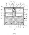
- the fluid dispenser according to the invention essentially comprises three component parts, namely a body 1, a bottom 2 and a follower piston 3.
- the distributor also comprises an outlet valve 4 or an attached nozzle.
- the dispenser may furthermore also be provided with a protective cover 5 which is removably mounted on the dispenser so as to mask the dispensing orifice.
- the body 1 is preferably made integrally of plastics material and comprises a barrel 11 of cylindrical shape, preferably circular, within which slides the follower piston 3, as will be seen below.
- the barrel 11 includes an open bottom end and an upper end which forms a shoulder 12 inwardly.
- the body 21 extends from this shoulder 12 upwards to form a ring 13 which can advantageously be used for fixing the protective cover 5.
- the body 1 forms a plate 14 which is here substantially circular.
- This plate 14 is substantially flat or concave and has a substantially central hole which will serve to define the dispensing orifice.
- a sleeve 16 extends from the hole towards the inside of the body so that the ring 13 extends concentrically with this sleeve 16.
- the plate 14 at the substantially central hole defines a hooking structure 144 which retains the valve 4.
- a hooking structure 144 which retains the valve 4.
- any outlet valve in the context of this invention for example can be used a valve in the form of a mushroom or umbrella comprising an anchor foot 41 engaged in the attachment structure 144 and a washer or corolla 42 whose edge comes into selective waterproof support on a valve seat 15 formed at the junction of the plate 14 with the sleeve 13 which defines the hole.
- the foot 41 can be fixed in place inside the attachment structure 144: in this case, the washer 42 is elastically deformable.
- the anchor foot 41 can move on a limited stroke inside the attachment structure 144: in this case, the washer 42 does not need to be elastically deformable.
- the washer 42 does not need to be elastically deformable.
- the protective cover 5 comprises a peripheral skirt 51 intended to come into frictional engagement, latching or screwing with the crown 13 and a cover wall 52 which covers the plate 14, with its central hole and its valve 4.
- the cover protection 5 can be entirely removed from the body 1, or alternatively, the cover can be hinged to the body.
- the cover 5 is made integrally with the body and connected thereto by a bridge of deformable material.
- the follower piston 3 conventionally comprises a sealing lip 31, which here is of the type with a double sealing contact.
- the sealing lip 31 is connected to a roof 32 which extends in its center by a axial conduit 33 which is open at both ends.
- the conduit 33 comprises a free end opposite the roof 32 and which forms a leaktight sliding lip 34.
- the conduit 33 is engaged inside the sleeve 16 so that the lip 34 can slide in a sealed manner inside the sleeve 16. It can also be envisaged that the conduit 33 is arranged around the sleeve 16: in this case, it is the free end of the sleeve 16 which is then provided with a sealing lip.
- the sealing lip 31 of the follower piston is engaged in leaktight sliding inside the barrel 11 of the body 1. In the initial starting position, the lip 31 is located in the upper part of the barrel 11. As and when of the use of the dispenser, this lip 31 will move towards the bottom of the barrel 11.
- the bottom 2 of the distributor is sealingly engaged in the open lower end of the barrel 11.
- the bottom 2 comprises a rigid annular cup 21 which is anchored on its outer periphery 22 in a sealed manner in the barrel 11.
- the inner periphery of the cup 21 is connected to a membrane 24 having a fixing heel connected to the cup.
- This elastically deformable membrane 24 is in the form of an annular dome which is closed at its center by an actuating wall 25.
- This wall 25 is situated substantially centrally with respect to the bottom 2 of the distributor.
- This actuating wall 25 is axially displaceable back and forth by deforming the flexible membrane 24. On the figure 1 the actuating wall 25 is in its rest position.
- the bottom 2 can be made integrally with a single plastic material.
- the bottom 2 can be made by bi-injection or co-molding from two different plastics.
- the bottom, and thus the actuating wall are in direct contact with the fluid, so that they form a tank wall element.
- the distributor On the figure 1 , the distributor is in its rest position with the tank 10 filled to the maximum, the lip 31 of the follower piston being in abutment against the shoulder 12.
- the valve 4 is closed so that there is no orifice of distribution.
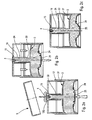
- the lip 34 is at its highest point in the sleeve 16. From this initial resting position, we will now describe, with reference to the Figures 2a, 2b and 2c a complete operating cycle of the dispenser according to the invention.
- the first step is to remove the cover 5, as shown in FIG. figure 2a . Then the user can exert pressure represented by the big arrow on the figure 2a at the level of the actuating wall 25. This has the effect of deforming the flexible membrane 24.
- the fluid product stored inside the tank 10 is put directly under pressure which has the effect of driving back part of the fluid product through the conduit 33 to the level of the valve 4 which is then forced in the open position to define an annular distribution port 150.
- This orifice is defined between the seat 15 and the washer 144.
- the follower piston remains static, with its sealing lip 31 in abutting contact with the shoulder 12.
- the distribution of the product continues until the actuating wall 25 reaches its maximum depressed position.
- the distribution of fluid product then stops at this moment and as soon as the pressure is released on the actuating wall 25, the valve 4 closes so that there is again no more orifice. 150.
- the wall 25 then returns to its initial rest position under the effect of the membrane 24 which tends to return to its original starting position because of its elastic shape memory.
- the membrane 24 therefore plays a role of return spring.
- the actuating wall 25 generates a depression inside the tank 10, which has the effect of sucking the follower piston 3 which then moves with a leaktight sliding inside. of the drum.
- the displacement of the follower piston is represented on the figure 2b by the two arrows on both sides of the conduit 33. Since this duct 33 is engaged in sealingly sliding inside the sleeve 16, the displacement of the follower piston in the barrel 11 also has the effect of moving the sealing lip 34 inside the sleeve 16.
- the follower piston makes a fluid connection between the reservoir 10 and the dispensing orifice.
- This fluidic connection makes it possible to produce a distributor without air intake whose reciprocating movable actuating wall is clearly separated from the dispensing orifice, and even situated on the opposite side.
- the actuating wall 25 is movable between two extreme positions, the fluid dispensing is perfectly metered. This produces a metering distributor without air intake whose actuating wall is located at the bottom and the dispensing orifice at the top. It is the follower piston itself which provides the connection between the reservoir and the dispensing orifice.
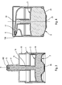
- the body 1 As for the body 1, it also comprises a shaft 11, a ring 13, a plate 14 and a sleeve 16, but it further comprises a dispensing nozzle 17 which terminates in a dispensing orifice 150.
- This dispenser also comprises a valve 4.
- the dispensing orifice 150 can also be made using a nozzle allowing a swirling of the fluid product.
- This nozzle can be integrated into the body 1 or made in the form of an insert.
- the distributor of the figure 3 comprises three component parts, namely the body 1, the bottom 2 and the follower piston 3.
- This dispenser can be used with one hand in the manner of a syringe, arranging the index and middle finger on the plate 14 from anterior part of the tip 17 and the thumb on the actuating wall 25. Unlike a conventional syringe, the fluid dispensing is perfectly dosed and the actuating wall returns to each actuation in its initial resting position.
- a dispenser may for example be used in pharmacies for the injection of various fluids into the natural orifices, such as nostrils or ears.
- the represented dispenser differs from that of the figure 3 essentially at the tip 17 and its bottom 2. Indeed, the tip is here more axial, but instead lateral.
- the dispensing orifice 150 is formed by a slotted shutter which opens under the pressure of the fluid product.
- the actuating wall 25 projects downwards and can thus constitute a bearing surface of the dispenser.
- the actuating wall is located at the bottom of the dispenser, but on the side or the top.
- the follower piston 3 can move horizontally.
Abstract
Description
La présente invention concerne un distributeur de produit fluide plus ou moins visqueux comme par exemple de la crème, du gel, de la patte, une lotion, un parfum, etc. Ce distributeur comprend un réservoir de produit fluide de volume variable dans lequel le produit fluide est stocké hors de contact de l'air. Le réservoir est pourvu d'une paroi d'actionnement déplaçable axialement en va-et-vient entre une position de repos et une position enfoncée. Le déplacement de la paroi fait varier la pression à l'intérieur du réservoir entre des phases de dépression et des phases de surpression. La paroi est située d'un côté du distributeur. D'autre part, le distributeur comprend un orifice de distribution par lequel le produit fluide est distribué hors du distributeur. L'orifice est pourvu d'un clapet de sortie anti-retour qui interdit une aspiration d'air à l'intérieur du réservoir. On rencontre fréquemment ce genre de distributeur dans les domaines de la parfumerie, de la cosmétique, de la pharmacie et de la parapharmacie.The present invention relates to a dispenser of more or less viscous fluid such as cream, gel, paw, lotion, perfume, etc. This dispenser comprises a fluid reservoir of variable volume in which the fluid product is stored out of contact with air. The reservoir is provided with an actuating wall axially displaceable back and forth between a rest position and a depressed position. The displacement of the wall varies the pressure inside the tank between vacuum phases and overpressure phases. The wall is located on one side of the dispenser. On the other hand, the dispenser comprises a dispensing orifice through which the fluid product is dispensed from the dispenser. The orifice is provided with a non-return check valve which prevents air from being drawn into the tank. This type of distributor is frequently found in the fields of perfumery, cosmetics, pharmacy and parapharmacy.
En général, dans ce genre de distributeur, la paroi d'actionnement est située à proximité de l'orifice de distribution de sorte que l'enfoncement de la paroi d'actionnement à pour effet direct de mettre le produit fluide stocké dans le réservoir sous pression de sorte qu'il est refoulé à travers l'orifice de distribution. Lorsqu'on relâche la paroi d'actionnement pour qu'elle retourne vers sa position de repos, le clapet de sortie se ferme : le réservoir est alors soumis à une dépression, ce qui a pour effet de modifier son volume utile. Cette variation de volume utile peut s'effectuer par exemple du fait que le réservoir est réalisé à partir d'une poche souple déformable. En variante, le réservoir forme un fût de coulissement dans lequel est engagé un piston suiveur. Dans le cas d'une poche souple, la dépression a pour effet de déformer la poche souple qui va se ratatiner sur elle-même. Dans le cas d'un piston suiveur, la dépression à l'intérieur du réservoir va déplacer le piston suiveur par aspiration. Dans les deux cas, le volume utile du réservoir diminue à mesure que du produit fluide en est extrait. De ce fait, il n'est pas possible d'installer la paroi d'actionnement n'importe où sur le réservoir, et en tout cas pas au niveau du fût de coulissement qui doit être indéformable. On ne peut pas non plus installer la paroi d'actionnement sur le piston suiveur. Donc, elle est généralement installée sur le haut du réservoir à proximité de l'orifice de distribution. Des distributeurs de ce type sont décris dans les documents
La présente invention a pour but de réaliser un distributeur de ce type ayant une configuration qui s'affranchit de cette contrainte de conception.The object of the present invention is to provide a dispenser of this type having a configuration that avoids this design constraint.
Pour ce faire, la présente invention propose un distributeur présentant les caractéristiques de la revendication principale.To do this, the present invention provides a dispenser having the features of the main claim.
Il s'agit là d'une forme de réalisation permettant de réaliser un réservoir de volume variable. Toutefois, étant donné que la paroi d'actionnement est située sur un autre côté que celui de l'orifice de distribution, la configuration est paradoxale, car il faut remarquer que la paroi d'actionnement n'agit pas directement sur le piston-suiveur, mais sur le produit fluide. Conventionnellement, le piston-suiveur est en bas, et l'orifice et la paroi d'actionnement en haut. Une difficulté surmontée par la présente invention est de découpler l'orifice et la paroi d'actionnement, tout en utilisant un piston-suiveur. Et pour ce faire, le piston suiveur peut former un conduit de liaison qui fait communiquer le réservoir avec l'orifice de distribution. Il est tout d'abord à noter que cette caractéristique peut être mise en oeuvre indépendamment du fait que la paroi d'actionnement soit opposée ou découplée de l'orifice de distribution. Toutefois, la combinaison de ces deux caractéristiques est avantageuse. Conventionnellement, le piston suiveur ne communique pas directement avec l'orifice de distribution. En effet, le piston suiveur est généralement situé au fond du réservoir et il se déplace par aspiration vers l'orifice de distribution. L'originalité de cette caractéristique réside dans le fait que le piston suiveur relie le réservoir à l'orifice de distribution.This is an embodiment for making a reservoir of variable volume. However, since the actuating wall is located on another side than that of the dispensing orifice, the configuration is paradoxical, because it should be noted that the actuating wall does not act directly on the follower piston. but on the fluid product. Conventionally, the follower piston is at the bottom, and the orifice and the actuating wall at the top. A difficulty overcome by the present invention is to decouple the orifice and the actuating wall, while using a follower piston. And to do this, the follower piston can form a connecting conduit which communicates the reservoir with the dispensing orifice. It should firstly be noted that this characteristic can be implemented independently of the fact that the actuating wall is opposite or uncoupled from the dispensing orifice. However, the combination of these two features is advantageous. Conventionally, the follower piston does not communicate directly with the dispensing orifice. Indeed, the follower piston is generally located at the bottom of the tank and it moves by suction towards the dispensing orifice. The originality of this feature lies in the fact that the follower piston connects the reservoir to the dispensing orifice.
Avantageusement, le distributeur de produit fluide comprend un bas et un haut, lorsqu'il est positionné debout, la paroi d'actionnement étant située en bas, le distributeur reposant, en position de repos et en position enfoncée, sur la paroi d'actionnement. L'actionnement du distributeur peut ainsi être effectué en appuyant sur le distributeur, alors que son fond repose sur une surface d'appui. Le produit est distribué sur le haut ou sur un côté latéral du distributeur.Advantageously, the fluid dispenser comprises a bottom and a top, when positioned upright, the actuating wall being located at the bottom, the distributor resting, in the rest position and in the depressed position, on the actuating wall. . The actuation of the dispenser can thus be performed by pressing the dispenser, while its bottom rests on a bearing surface. The product is dispensed on the top or side of the dispenser.
Avantageusement, la paroi et le piston suiveur se déplacent selon un axe commun X. Ils sont séparés par le produit fluide stocké dans le réservoir. A chaque enfoncement de la paroi, du produit fluide est distribué et le piston suiveur reste statique et à chaque relâchement de la paroi le piston suiveur se déplace.Advantageously, the wall and the follower piston move along a common axis X. They are separated by the fluid product stored in the reservoir. At each depression of the wall, fluid is dispensed and the follower piston remains static and at each release of the wall the follower piston moves.
Avantageusement, le conduit est en prise coulissante étanche avec un manchon solidaire de l'orifice de distribution, le conduit et le manchon coulissant l'un par rapport à l'autre à mesure que le piston suiveur se déplace dans le fût. Bien entendu, comme dans tout distributeur classique à piston suiveur, ce dernier doit pouvoir se déplacer par rapport à l'orifice de distribution. Ce déplacement est ici possible grâce à l'engagement coulissant étanche entre le piston suiveur et l'orifice de distribution. Selon une forme de réalisation pratique, le fût, le manchon et l'orifice de distribution sont formés par un corps monobloc. De préférence, le corps comprend un plateau supérieur formant le haut du distributeur, le plateau étant formé avec un trou qui est avantageusement pourvu d'un clapet de sortie, de manière à former ensemble l'orifice de distribution. On peut ainsi noter que le distributeur peut être réalisé à partir de trois pièces uniquement, à savoir le corps monobloc, le piston suiveur et la paroi d'actionnement, si l'on omet le clapet de sortie.Advantageously, the conduit is in leaktight sliding engagement with a sleeve integral with the dispensing orifice, the conduit and the sleeve sliding relative to each other as the follower piston moves in the barrel. Of course, as in any conventional piston follower, it must be able to move relative to the dispensing orifice. This displacement is here possible thanks to the sliding sliding engagement between the follower piston and the dispensing orifice. According to a practical embodiment, the barrel, the sleeve and the dispensing orifice are formed by a one-piece body. Preferably, the body comprises an upper plate forming the top of the dispenser, the plate being formed with a hole which is advantageously provided with an outlet valve, so as to form together the dispensing orifice. It can thus be noted that the dispenser can be made from only three parts, namely the one-piece body, the follower piston and the actuating wall, if the outlet valve is omitted.
Selon un autre aspect de l'invention, le distributeur peut comprendre un corps monobloc définissant intérieurement le réservoir de produit fluide, le corps étant obturé par un fond formant la paroi d'actionnement. Avantageusement, le réservoir est principalement formé par le fond, le corps et un piston suiveur, ce piston suiveur étant positionné entre le fond et l'orifice de distribution. Avantageusement, le corps forme un manchon solidaire de l'orifice de distribution, le piston suiveur formant un conduit engagé à coulissement étanche dans le manchon, le réservoir communiquant ainsi avec l'orifice de distribution à travers le conduit et le manchon.According to another aspect of the invention, the dispenser may comprise a one-piece body internally defining the fluid reservoir, the body being closed by a bottom forming the actuating wall. Advantageously, the reservoir is mainly formed by the bottom, the body and a follower piston, this follower piston being positioned between the bottom and the dispensing orifice. Advantageously, the body forms a sleeve integral with the dispensing orifice, the follower piston forming a duct engaged in leaktight sliding in the sleeve, the reservoir thus communicating with the dispensing orifice through the duct and the sleeve.
La configuration originale du distributeur selon l'invention, à savoir d'opposer ou de dissocier la paroi d'actionnement et l'orifice de distribution, est ici permise grâce à l'utilisation d'un piston suiveur qui relie le réservoir à l'orifice de distribution. Toutefois, cette dernière caractéristique peut être protégée isolément.The original configuration of the dispenser according to the invention, namely to oppose or dissociate the actuating wall and the dispensing orifice, is here permitted thanks to the use of a follower piston which connects the reservoir to the dispensing orifice. However, this last characteristic can be protected in isolation.
L'invention sera maintenant plus amplement décrite en référence aux dessins joints donnant à titre d'exemples non limitatifs deux modes de réalisation de l'invention.The invention will now be more fully described with reference to the accompanying drawings giving by way of nonlimiting examples two embodiments of the invention.
Sur les figures :
- la
figure 1 est une vue en section transversale verticale à travers un distributeur de produit fluide selon l'invention à l'état de repos, - les
figures 2a, 2b et 2c représentent le distributeur de lafigure 1 au cours de différentes phases du cycle de fonctionnement du distributeur, - la
figure 3 est une vue similaire à celle de lafigure 1 pour une variante de réalisation de l'invention, et - la
figure 4 est une vue similaire à celle de lafigure 3 pour une autre variante de réalisation de l'invention.
- the
figure 1 is a vertical cross-sectional view through a fluid dispenser according to the invention in the state of rest, - the
Figures 2a, 2b and 2c represent the distributor of thefigure 1 during different phases of the dispenser operating cycle, - the
figure 3 is a view similar to that of thefigure 1 for an alternative embodiment of the invention, and - the
figure 4 is a view similar to that of thefigure 3 for another variant embodiment of the invention.
Le distributeur de produit fluide selon l'invention comprend essentiellement trois pièces constitutives, à savoir un corps 1, un fond 2 et un piston suiveur 3. Le distributeur comprend également un clapet de sortie 4 ou un gicleur rapporté. Le distributeur peut en outre également être pourvu d'un capot de protection 5 qui est monté de manière amovible sur le distributeur de manière à en masquer l'orifice de distribution.The fluid dispenser according to the invention essentially comprises three component parts, namely a
Le corps 1 est de préférence réalisé de manière monobloc en matière plastique et comprend un fût 11 de forme cylindrique, avantageusement circulaire, à l'intérieur duquel coulisse le piston suiveur 3, comme on le verra ci-après. Le fût 11 comprend une extrémité inférieure ouverte et une extrémité supérieure qui forme un épaulement 12 vers l'intérieur. Le corps 21 se prolonge à partir de cet épaulement 12 vers le haut pour former une couronne 13 qui peut avantageusement servir à la fixation du capot de protection 5. Au-delà de la couronne 13, le corps 1 forme un plateau 14 qui est ici sensiblement circulaire. Ce plateau 14 est sensiblement plan ou concave et comporte un trou sensiblement central qui va servir à définir l'orifice de distribution. Un manchon 16 s'étend à partir du trou vers l'intérieur du corps de sorte que la couronne 13 s'étend de manière concentrique avec ce manchon 16. L'extrémité inférieure du manchon 16 s'étend jusqu'au niveau du fût 11. Optionnellement, le plateau 14 au niveau du trou sensiblement central définit une structure d'accrochage 144 qui permet de retenir le clapet 4. En effet, bien que l'on puisse utiliser n'importe quel clapet de sortie dans le cadre de la présente invention, on peut par exemple utiliser un clapet sous la forme d'un champignon ou d'une ombrelle comprenant un pied d'ancrage 41 engagé dans la structure d'accrochage 144 et une rondelle ou corolle 42 dont le bord vient en appui sélectif étanche sur un siège de clapet 15 formé au niveau de la jonction du plateau 14 avec le manchon 13 qui définit le trou. Le pied 41 peut être fixé en place à l'intérieur de la structure d'accrochage 144 : dans ce cas, la rondelle 42 est élastiquement déformable. En variante, le pied d'ancrage 41 peut se déplacer sur une course limitée à l'intérieur de la structure d'accrochage 144 : dans ce cas, la rondelle 42 n'a pas besoin d'être élastiquement déformable. A la place de ce clapet particulier, on peut bien entendu utiliser un autre type de clapet, ou encore un obturateur, par exemple à fente. On peut même envisager qu'il n'y ait pas du tout de clapet, de sorte que le trou définit l'orifice de distribution.The
Le capot de protection 5 comprend une jupe périphérique 51 destinée à venir en prise par frottement, encliquetage ou vissage avec la couronne 13 et une paroi de couvercle 52 qui vient recouvrir le plateau 14, avec son trou central et son clapet 4. Le capot de protection 5 peut être entièrement retiré du corps 1, ou en variante, le capot peut être articulé sur le corps. On peut également imaginer que le capot 5 soit réalisé de manière monobloc avec le corps et relié à celui-ci par un pont de matière déformable.The
Le piston suiveur 3 comprend de manière classique une lèvre d'étanchéité 31, qui et ici du type à double contact de coulissement étanche. La lèvre d'étanchéité 31 est reliée à un toit 32 qui se prolonge en son centre par un conduit axial 33 qui est ouvert à ses deux extrémités. Le conduit 33 comprend une extrémité libre opposée au toit 32 et qui forme une lèvre de coulissement étanche 34. Le conduit 33 est engagé à l'intérieur du manchon 16 de sorte que la lèvre 34 peut coulisser de manière étanche à l'intérieur du manchon 16. On peut également envisager que le conduit 33 soit disposé autour du manchon 16 : dans ce cas, c'est l'extrémité libre du manchon 16 qui est alors pourvue d'une lèvre d'étanchéité. La lèvre d'étanchéité 31 du piston suiveur est engagée à coulissement étanche à l'intérieur du fût 11 du corps 1. Dans la position initiale de départ, la lèvre 31 est située dans la partie haute du fût 11. Au fur et à mesure de l'utilisation du distributeur, cette lèvre 31 va se déplacer vers le bas du fût 11.The
D'autre part, le fond 2 du distributeur est engagé de manière étanche dans l'extrémité inférieure ouverte du fût 11. Le fond 2 comprend une coupelle annulaire rigide 21 qui est ancrée sur sa périphérie extérieure 22 de manière étanche dans le fût 11. La périphérie intérieure de la coupelle 21 est reliée à une membrane 24 présentant un talon de fixation relié à la coupelle. Cette membrane élastiquement déformable 24 se présente sous la forme d'un dôme annulaire qui est fermé en son centre par une paroi d'actionnement 25. Cette paroi 25 est située de manière sensiblement centrale par rapport au fond 2 du distributeur. Cette paroi d'actionnement 25 est déplaçable axialement en va-et-vient en déformant la membrane souple 24. Sur la
Il est à noter que le fond, et de ce fait la paroi d'actionnement, sont au contact direct du produit fluide, de sorte qu'ils forment un élément de paroi de réservoir.It should be noted that the bottom, and thus the actuating wall, are in direct contact with the fluid, so that they form a tank wall element.
En se référant à nouveau à la
Sur la
On vient ainsi de voir que le piston suiveur réalise une liaison fluidique entre le réservoir 10 et l'orifice de distribution. Cette liaison fluidique permet de réaliser un distributeur sans reprise d'air dont la paroi d'actionnement mobile en va-et-vient est clairement séparée de l'orifice de distribution, et même située à l'opposé. En outre, étant donné que la paroi d'actionnement 25 est déplaçable entre deux positions extrêmes, la distribution de produit fluide est parfaitement dosée. On obtient ainsi un distributeur doseur sans reprise d'air dont la paroi d'actionnement est située au fond et l'orifice de distribution en haut. C'est le piston suiveur lui-même qui assure la liaison entre le réservoir et l'orifice de distribution.It has just been seen that the follower piston makes a fluid connection between the
On se référera maintenant à la
Sur la
On peut bien entendu encore imaginer d'autres formes de réalisation dans lesquelles la paroi d'actionnement n'est située au fond du distributeur, mais sur le côté ou le dessus. De même, le piston-suiveur 3 peut se déplacer horizontalement.It is of course still possible to imagine other embodiments in which the actuating wall is located at the bottom of the dispenser, but on the side or the top. Similarly, the
Grâce à l'invention on dispose d'un distributeur dont le produit fluide est stocké à l'abri de l'air et dont l'actionnement est découplé spatialement de la distribution.Thanks to the invention there is a distributor whose fluid product is stored away from air and whose actuation is spatially decoupled from the distribution.
Claims (11)
- A fluid dispenser comprising:• a fluid reservoir (10) of variable working volume, in which reservoir the fluid is protected from the air, the reservoir being provided with an actuator wall (25) that is axially movable down and up between a rest position and a depressed position, the movement of the wall causing the pressure in the reservoir to vary, the wall being situated at an end of the dispenser; and• a dispenser orifice (150) via which the fluid is dispensed, the orifice being provided with an outlet valve (4); the orifice (150) being situated at an end of the dispenser other than the end at which the actuator wall (25) is situated,the dispenser being characterized in that the reservoir (10) forms a slide cylinder (11) in which there is engaged a follower piston (3) that is suitable for sliding in leaktight manner in the cylinder.
- A fluid dispenser according to claim 1, including a bottom and a top when it is positioned upright, the actuator wall (25) being situated at the bottom, with the dispenser bearing, in its rest position and in its depressed position, against the actuator wall.
- A fluid dispenser according to claim 1, including a bottom, a top, and side walls, the actuator wall is situated on a side wall and the dispenser orifice is situated at the top.
- A fluid dispenser according to claim 1, claim 2 or claim 3, in which the wall (25) and the follower piston (3) move along a common axis X.
- A fluid dispenser according to any preceding claim, in which the follower piston (3) forms a connection duct (33) that puts the reservoir into communication with the dispenser orifice (150).
- A fluid dispenser according to claim 5, in which the duct (33) is slidably engaged in leaktight manner in a sleeve (16) that is secured to the dispenser orifice (150), the duct and the sleeve sliding relative to each other as the follower piston (3) moves in the cylinder.
- A fluid dispenser according to claim 6, in which the cylinder (11), the sleeve (16), and the dispenser orifice (150) are formed by a one-piece body (1).
- A fluid dispenser according to claim 7, in which the body (1) includes a top plate (14) forming the top of the dispenser, the plate (14) being formed with a hole that is advantageously provided with an outlet valve (4), said hole and said outlet valve co-operating with each other to form the dispenser orifice (150).
- A fluid dispenser according to any preceding claim, including a one-piece body (1) that internally defines the fluid reservoir (10), the body being closed by a bottom wall (2) that forms the actuator wall (25).
- A fluid dispenser according to claim 9, in which the reservoir (10) is mainly formed by the bottom wall (2), the body (1), and a follower piston (3), the follower piston being positioned between the bottom wall and the dispenser orifice.
- A fluid dispenser according to claim 10, in which the body (1) forms a sleeve (16) that is secured to the dispenser orifice (150), the follower piston (3) forming a duct (33) that is slidably engaged in leaktight manner in the sleeve (16), the reservoir (10) thus communicating with the dispenser orifice (150) via the duct and the sleeve.
Applications Claiming Priority (2)
| Application Number | Priority Date | Filing Date | Title |
|---|---|---|---|
| FR0652780A FR2903092B1 (en) | 2006-07-03 | 2006-07-03 | FLUID PRODUCT DISPENSER |
| PCT/FR2007/051572 WO2008003894A2 (en) | 2006-07-03 | 2007-07-02 | Fluid product dispenser |
Publications (2)
| Publication Number | Publication Date |
|---|---|
| EP2043927A2 EP2043927A2 (en) | 2009-04-08 |
| EP2043927B1 true EP2043927B1 (en) | 2010-09-15 |
Family
ID=37685845
Family Applications (1)
| Application Number | Title | Priority Date | Filing Date |
|---|---|---|---|
| EP07823528A Active EP2043927B1 (en) | 2006-07-03 | 2007-07-02 | Fluid product dispenser |
Country Status (8)
| Country | Link |
|---|---|
| US (1) | US8556131B2 (en) |
| EP (1) | EP2043927B1 (en) |
| CN (1) | CN101500906B (en) |
| BR (1) | BRPI0713392A2 (en) |
| DE (1) | DE602007009252D1 (en) |
| ES (1) | ES2351889T3 (en) |
| FR (1) | FR2903092B1 (en) |
| WO (1) | WO2008003894A2 (en) |
Families Citing this family (14)
| Publication number | Priority date | Publication date | Assignee | Title |
|---|---|---|---|---|
| FR2957335B1 (en) * | 2010-03-11 | 2012-09-14 | Cadorit Ag | CONTAINER |
| IT1399127B1 (en) * | 2010-04-01 | 2013-04-05 | Lameplast Spa | DEVICE FOR THE ADMINISTRATION OF FLUID PRODUCTS |
| CN101936969A (en) * | 2010-08-11 | 2011-01-05 | 苏州大学 | Sample applicator |
| KR101598120B1 (en) * | 2013-06-25 | 2016-02-26 | (주)연우 | Extrusion type cosmetic container |
| DE102013214231B3 (en) * | 2013-07-19 | 2014-11-06 | Aptar Radolfzell Gmbh | Discharge head and dispenser for a preferably pasty medium |
| CN203399790U (en) * | 2013-08-16 | 2014-01-22 | 汕头市京华塑胶有限公司 | Foundation make-up extrusion pump |
| MX2016012684A (en) * | 2014-03-31 | 2017-05-01 | Amcor Ltd | Controlled release container. |
| FR3052446B1 (en) * | 2016-06-10 | 2018-07-13 | Karine Courtin | DEVICE FOR DISPENSING FLUID PRODUCT |
| US10750923B2 (en) | 2016-07-29 | 2020-08-25 | Spontex S.A.S. | Rinsing device |
| EP3580142B1 (en) * | 2017-02-10 | 2021-05-26 | Dexos Drinks Limited | A beverage container with a dispenser |
| GB2559594B (en) * | 2017-02-10 | 2020-07-15 | Dexos Drinks Ltd | A liquid dispenser and method |
| FR3077222B1 (en) * | 2018-01-26 | 2023-12-01 | Aptar France Sas | FLUID PRODUCT DISPENSER |
| KR101915937B1 (en) * | 2018-07-04 | 2018-11-06 | 김진우 | The foundation container having a exhaust pump |
| US11365043B2 (en) | 2020-03-04 | 2022-06-21 | Rennie West | Fluid dispensing system |
Family Cites Families (15)
| Publication number | Priority date | Publication date | Assignee | Title |
|---|---|---|---|---|
| US2443981A (en) * | 1945-03-19 | 1948-06-22 | Frank F Funk | Grease gun charger |
| US2898007A (en) * | 1956-01-17 | 1959-08-04 | Flo Container Inc | Elastic container with reciprocating plunger |
| US4175704A (en) * | 1976-02-17 | 1979-11-27 | Cohen Milton J | Non-aerosol continuous spray dispenser |
| US4205766A (en) * | 1976-03-16 | 1980-06-03 | White Douglas J | Dual compartment dispensing container |
| DE8030266U1 (en) * | 1980-11-13 | 1981-03-12 | Max Hübner GmbH & Co, 8950 Kaufbeuren | Container with sliding dispensing plunger |
| DE3305898A1 (en) * | 1983-02-19 | 1984-08-23 | Günter 7535 Königsbach-Stein Hirsch | Fluid dispenser |
| US4533069A (en) * | 1983-10-31 | 1985-08-06 | The Procter & Gamble Company | Pump-type dispenser |
| US5257726A (en) * | 1985-08-14 | 1993-11-02 | Ing. Erich Pfeiffer Gmbh & Co. Kg | Dispenser for flowable media |
| NL8900170A (en) * | 1989-01-24 | 1990-08-16 | Douwe Egberts Tabaksfab | DOSAGE HOLDER. |
| FR2765560B1 (en) * | 1997-07-02 | 1999-08-13 | Oreal | DISPENSER FOR A LIQUID OR PASTY PRODUCT COMPRISING IMPROVED PUMPING MEANS |
| DE19729516C2 (en) * | 1997-07-10 | 1999-04-22 | Georg Wiegner | Pump for the dosed discharge of liquid, gel-like or viscous substances |
| NL1010749C2 (en) * | 1998-12-07 | 2000-06-08 | V O F Pharmasept | Holder for dosed and substantially germ-free dispensing of a liquid. |
| FR2821831B1 (en) * | 2001-03-06 | 2003-08-01 | Airlessystems | SAMPLE DISPENSER OF FLUID COSMETIC PRODUCT |
| FR2826245B1 (en) * | 2001-06-25 | 2003-08-15 | Airlessystems | FLUID COSMETIC SAMPLE DISPENSER |
| US20060196889A1 (en) * | 2006-04-20 | 2006-09-07 | Masatoshi Masuda | Fluid storage container with piston provided inside |
-
2006
- 2006-07-03 FR FR0652780A patent/FR2903092B1/en not_active Expired - Fee Related
-
2007
- 2007-07-02 DE DE602007009252T patent/DE602007009252D1/en active Active
- 2007-07-02 EP EP07823528A patent/EP2043927B1/en active Active
- 2007-07-02 BR BRPI0713392-8A patent/BRPI0713392A2/en not_active IP Right Cessation
- 2007-07-02 WO PCT/FR2007/051572 patent/WO2008003894A2/en active Application Filing
- 2007-07-02 ES ES07823528T patent/ES2351889T3/en active Active
- 2007-07-02 US US12/307,062 patent/US8556131B2/en active Active
- 2007-07-02 CN CN200780029662XA patent/CN101500906B/en not_active Expired - Fee Related
Also Published As
| Publication number | Publication date |
|---|---|
| US20090230152A1 (en) | 2009-09-17 |
| EP2043927A2 (en) | 2009-04-08 |
| WO2008003894A2 (en) | 2008-01-10 |
| FR2903092A1 (en) | 2008-01-04 |
| BRPI0713392A2 (en) | 2012-04-17 |
| CN101500906A (en) | 2009-08-05 |
| WO2008003894A3 (en) | 2008-02-21 |
| FR2903092B1 (en) | 2008-10-17 |
| CN101500906B (en) | 2011-12-28 |
| US8556131B2 (en) | 2013-10-15 |
| DE602007009252D1 (en) | 2010-10-28 |
| ES2351889T3 (en) | 2011-02-11 |
Similar Documents
| Publication | Publication Date | Title |
|---|---|---|
| EP2043927B1 (en) | Fluid product dispenser | |
| EP2021130B1 (en) | Fluid product dispensing member and dispenser comprising same | |
| EP1991476B1 (en) | Dispensing nozzle for a dispenser of fluid product | |
| WO2008142308A1 (en) | Device for dispensing a liquid to pasty product with a dosing pump | |
| WO2009024694A2 (en) | Stopper valve and method for making such valve | |
| EP1606063B1 (en) | Fluid product distribution body and fluid product distributor comprising such a body | |
| EP2838667B1 (en) | Container for a fluid product, and dispenser using such a container | |
| WO2006048578A1 (en) | Flexible part forming an output valve and a return spring for a dispensing device | |
| EP2442914B1 (en) | Fluid material dispenser | |
| EP1670700A2 (en) | Fluid product dispensing head | |
| WO2014096722A1 (en) | Refillable fluid product dispenser | |
| FR2884157A1 (en) | HEAD OF DISTRIBUTION | |
| EP3451870B1 (en) | Device for packaging and dispensing a product, notably a cosmetic product | |
| FR2928357A1 (en) | Shutter i.e. deliver flap, for e.g. pump of flexible bag-type reservoir in cosmetics field, has slot area with wall thickness larger than wall thickness of deformation zone such that slot area is more rigid than deformation zone | |
| EP3417948B1 (en) | Moulded pump for dispensing a fluid product | |
| EP1633647B1 (en) | Fluid product dispenser | |
| EP1706212B1 (en) | Fluid product dispensing pump | |
| FR2877325A1 (en) | Viscous fluid product e.g. lotion, dispensing unit e.g. pump, for e.g. cosmetic field, has elastically deformable part formed by monoblock part forming rigid part displaced axially in to and fro manner by deforming deformable part | |
| EP0277893A1 (en) | Distributor for pasty products with a rotating axial actuator | |
| FR3077222A1 (en) | FLUID PRODUCT DISPENSER | |
| WO2005063404A1 (en) | Fluid product dispensing member | |
| EP1703986B1 (en) | Fluid product dispensing member | |
| EP0805719B1 (en) | Pump with a single-piece inlet valve and assembly for moulding said valve | |
| EP3814019B1 (en) | Fluid product dispenser | |
| FR3003480A1 (en) | RECHARGEABLE FLUID PRODUCT DISPENSER. |
Legal Events
| Date | Code | Title | Description |
|---|---|---|---|
| PUAI | Public reference made under article 153(3) epc to a published international application that has entered the european phase |
Free format text: ORIGINAL CODE: 0009012 |
|
| 17P | Request for examination filed |
Effective date: 20090123 |
|
| AK | Designated contracting states |
Kind code of ref document: A2 Designated state(s): AT BE BG CH CY CZ DE DK EE ES FI FR GB GR HU IE IS IT LI LT LU LV MC MT NL PL PT RO SE SI SK TR |
|
| AX | Request for extension of the european patent |
Extension state: AL BA HR MK RS |
|
| RBV | Designated contracting states (corrected) |
Designated state(s): DE ES FR GB IT |
|
| DAX | Request for extension of the european patent (deleted) | ||
| 17Q | First examination report despatched |
Effective date: 20091109 |
|
| GRAP | Despatch of communication of intention to grant a patent |
Free format text: ORIGINAL CODE: EPIDOSNIGR1 |
|
| RIN1 | Information on inventor provided before grant (corrected) |
Inventor name: BEHAR, ALAIN Inventor name: DECOTTIGNIES, LAURENT |
|
| GRAS | Grant fee paid |
Free format text: ORIGINAL CODE: EPIDOSNIGR3 |
|
| GRAA | (expected) grant |
Free format text: ORIGINAL CODE: 0009210 |
|
| AK | Designated contracting states |
Kind code of ref document: B1 Designated state(s): DE ES FR GB IT |
|
| REG | Reference to a national code |
Ref country code: GB Ref legal event code: FG4D Free format text: NOT ENGLISH |
|
| REF | Corresponds to: |
Ref document number: 602007009252 Country of ref document: DE Date of ref document: 20101028 Kind code of ref document: P |
|
| REG | Reference to a national code |
Ref country code: ES Ref legal event code: FG2A Effective date: 20110201 |
|
| PLBE | No opposition filed within time limit |
Free format text: ORIGINAL CODE: 0009261 |
|
| STAA | Information on the status of an ep patent application or granted ep patent |
Free format text: STATUS: NO OPPOSITION FILED WITHIN TIME LIMIT |
|
| 26N | No opposition filed |
Effective date: 20110616 |
|
| REG | Reference to a national code |
Ref country code: DE Ref legal event code: R097 Ref document number: 602007009252 Country of ref document: DE Effective date: 20110616 |
|
| REG | Reference to a national code |
Ref country code: DE Ref legal event code: R082 Ref document number: 602007009252 Country of ref document: DE Representative=s name: BITTNER & PARTNER, DE |
|
| REG | Reference to a national code |
Ref country code: DE Ref legal event code: R082 Ref document number: 602007009252 Country of ref document: DE Representative=s name: STAUDT IP LAW, DE Effective date: 20130715 Ref country code: DE Ref legal event code: R081 Ref document number: 602007009252 Country of ref document: DE Owner name: APTAR FRANCE SAS, FR Free format text: FORMER OWNER: AIRLESSYSTEMS, CHARLEVAL, FR Effective date: 20130715 Ref country code: DE Ref legal event code: R082 Ref document number: 602007009252 Country of ref document: DE Representative=s name: BITTNER & PARTNER, DE Effective date: 20130715 |
|
| PGFP | Annual fee paid to national office [announced via postgrant information from national office to epo] |
Ref country code: ES Payment date: 20130716 Year of fee payment: 7 |
|
| PGFP | Annual fee paid to national office [announced via postgrant information from national office to epo] |
Ref country code: GB Payment date: 20130719 Year of fee payment: 7 |
|
| PGFP | Annual fee paid to national office [announced via postgrant information from national office to epo] |
Ref country code: IT Payment date: 20130711 Year of fee payment: 7 |
|
| REG | Reference to a national code |
Ref country code: GB Ref legal event code: 732E Free format text: REGISTERED BETWEEN 20140123 AND 20140129 |
|
| REG | Reference to a national code |
Ref country code: ES Ref legal event code: PC2A Owner name: VALOIS S.A.S. Effective date: 20141028 |
|
| REG | Reference to a national code |
Ref country code: ES Ref legal event code: PC2A Owner name: APTAR FRANCE S.A.S. Effective date: 20141029 |
|
| REG | Reference to a national code |
Ref country code: ES Ref legal event code: PC2A Owner name: APTAR FRANCE SAS Effective date: 20141121 |
|
| GBPC | Gb: european patent ceased through non-payment of renewal fee |
Effective date: 20140702 |
|
| PG25 | Lapsed in a contracting state [announced via postgrant information from national office to epo] |
Ref country code: IT Free format text: LAPSE BECAUSE OF NON-PAYMENT OF DUE FEES Effective date: 20140702 |
|
| PG25 | Lapsed in a contracting state [announced via postgrant information from national office to epo] |
Ref country code: GB Free format text: LAPSE BECAUSE OF NON-PAYMENT OF DUE FEES Effective date: 20140702 |
|
| REG | Reference to a national code |
Ref country code: DE Ref legal event code: R082 Ref document number: 602007009252 Country of ref document: DE Representative=s name: STAUDT IP LAW, DE |
|
| REG | Reference to a national code |
Ref country code: FR Ref legal event code: PLFP Year of fee payment: 9 |
|
| REG | Reference to a national code |
Ref country code: FR Ref legal event code: PLFP Year of fee payment: 10 |
|
| PG25 | Lapsed in a contracting state [announced via postgrant information from national office to epo] |
Ref country code: ES Free format text: LAPSE BECAUSE OF NON-PAYMENT OF DUE FEES Effective date: 20140703 |
|
| REG | Reference to a national code |
Ref country code: FR Ref legal event code: PLFP Year of fee payment: 11 |
|
| REG | Reference to a national code |
Ref country code: FR Ref legal event code: PLFP Year of fee payment: 12 |
|
| PGFP | Annual fee paid to national office [announced via postgrant information from national office to epo] |
Ref country code: DE Payment date: 20220624 Year of fee payment: 16 |
|
| P01 | Opt-out of the competence of the unified patent court (upc) registered |
Effective date: 20230525 |
|
| P02 | Opt-out of the competence of the unified patent court (upc) changed |
Effective date: 20230527 |
|
| PGFP | Annual fee paid to national office [announced via postgrant information from national office to epo] |
Ref country code: FR Payment date: 20230728 Year of fee payment: 17 |
|
| REG | Reference to a national code |
Ref country code: DE Ref legal event code: R082 Ref document number: 602007009252 Country of ref document: DE Representative=s name: SONNENBERG HARRISON PARTNERSCHAFT MBB PATENT- , DE |
|
| REG | Reference to a national code |
Ref country code: DE Ref legal event code: R119 Ref document number: 602007009252 Country of ref document: DE |