EP2043708B1 - Medical delivery system with asymmetrical coding means - Google Patents
Medical delivery system with asymmetrical coding means Download PDFInfo
- Publication number
- EP2043708B1 EP2043708B1 EP07787550A EP07787550A EP2043708B1 EP 2043708 B1 EP2043708 B1 EP 2043708B1 EP 07787550 A EP07787550 A EP 07787550A EP 07787550 A EP07787550 A EP 07787550A EP 2043708 B1 EP2043708 B1 EP 2043708B1
- Authority
- EP
- European Patent Office
- Prior art keywords
- container
- fastening means
- dosing assembly
- delivery system
- medical delivery
- Prior art date
- Legal status (The legal status is an assumption and is not a legal conclusion. Google has not performed a legal analysis and makes no representation as to the accuracy of the status listed.)
- Active
Links
- 239000003814 drug Substances 0.000 claims description 53
- 238000007373 indentation Methods 0.000 claims description 27
- 230000008878 coupling Effects 0.000 claims description 8
- 238000010168 coupling process Methods 0.000 claims description 8
- 238000005859 coupling reaction Methods 0.000 claims description 8
- 229940079593 drug Drugs 0.000 description 15
- NOESYZHRGYRDHS-UHFFFAOYSA-N insulin Chemical compound N1C(=O)C(NC(=O)C(CCC(N)=O)NC(=O)C(CCC(O)=O)NC(=O)C(C(C)C)NC(=O)C(NC(=O)CN)C(C)CC)CSSCC(C(NC(CO)C(=O)NC(CC(C)C)C(=O)NC(CC=2C=CC(O)=CC=2)C(=O)NC(CCC(N)=O)C(=O)NC(CC(C)C)C(=O)NC(CCC(O)=O)C(=O)NC(CC(N)=O)C(=O)NC(CC=2C=CC(O)=CC=2)C(=O)NC(CSSCC(NC(=O)C(C(C)C)NC(=O)C(CC(C)C)NC(=O)C(CC=2C=CC(O)=CC=2)NC(=O)C(CC(C)C)NC(=O)C(C)NC(=O)C(CCC(O)=O)NC(=O)C(C(C)C)NC(=O)C(CC(C)C)NC(=O)C(CC=2NC=NC=2)NC(=O)C(CO)NC(=O)CNC2=O)C(=O)NCC(=O)NC(CCC(O)=O)C(=O)NC(CCCNC(N)=N)C(=O)NCC(=O)NC(CC=3C=CC=CC=3)C(=O)NC(CC=3C=CC=CC=3)C(=O)NC(CC=3C=CC(O)=CC=3)C(=O)NC(C(C)O)C(=O)N3C(CCC3)C(=O)NC(CCCCN)C(=O)NC(C)C(O)=O)C(=O)NC(CC(N)=O)C(O)=O)=O)NC(=O)C(C(C)CC)NC(=O)C(CO)NC(=O)C(C(C)O)NC(=O)C1CSSCC2NC(=O)C(CC(C)C)NC(=O)C(NC(=O)C(CCC(N)=O)NC(=O)C(CC(N)=O)NC(=O)C(NC(=O)C(N)CC=1C=CC=CC=1)C(C)C)CC1=CN=CN1 NOESYZHRGYRDHS-UHFFFAOYSA-N 0.000 description 5
- 230000000712 assembly Effects 0.000 description 4
- 238000000429 assembly Methods 0.000 description 4
- 239000011521 glass Substances 0.000 description 3
- 102000004877 Insulin Human genes 0.000 description 2
- 108090001061 Insulin Proteins 0.000 description 2
- 230000004308 accommodation Effects 0.000 description 2
- 230000008901 benefit Effects 0.000 description 2
- 230000009969 flowable effect Effects 0.000 description 2
- 239000012530 fluid Substances 0.000 description 2
- 238000001802 infusion Methods 0.000 description 2
- 229940125396 insulin Drugs 0.000 description 2
- 239000007788 liquid Substances 0.000 description 2
- 239000000463 material Substances 0.000 description 2
- 238000012986 modification Methods 0.000 description 2
- 230000004048 modification Effects 0.000 description 2
- 239000004033 plastic Substances 0.000 description 2
- 108090000623 proteins and genes Proteins 0.000 description 2
- 230000000717 retained effect Effects 0.000 description 2
- WKBPZYKAUNRMKP-UHFFFAOYSA-N 1-[2-(2,4-dichlorophenyl)pentyl]1,2,4-triazole Chemical compound C=1C=C(Cl)C=C(Cl)C=1C(CCC)CN1C=NC=N1 WKBPZYKAUNRMKP-UHFFFAOYSA-N 0.000 description 1
- VOUAQYXWVJDEQY-QENPJCQMSA-N 33017-11-7 Chemical compound OC(=O)CC[C@H](N)C(=O)N[C@@H](C)C(=O)N[C@@H](CCC(O)=O)C(=O)N[C@@H](CC(O)=O)C(=O)N[C@@H](CC(C)C)C(=O)N[C@@H](CCC(N)=O)C(=O)N[C@@H](C(C)C)C(=O)NCC(=O)N[C@@H](CCC(N)=O)C(=O)N[C@@H](C(C)C)C(=O)N[C@@H](CCC(O)=O)C(=O)N[C@@H](CC(C)C)C(=O)NCC(=O)NCC(=O)NCC(=O)N1CCC[C@H]1C(=O)NCC(=O)N[C@@H](C)C(=O)NCC(=O)N[C@@H](CO)C(=O)N[C@@H](CC(C)C)C(=O)N[C@@H](CCC(N)=O)C(=O)N1[C@H](C(=O)N[C@@H](CC(C)C)C(=O)N[C@@H](C)C(=O)N[C@@H](CC(C)C)C(=O)N[C@@H](CCC(O)=O)C(=O)NCC(=O)N[C@@H](CO)C(=O)N[C@@H](CC(C)C)C(=O)N[C@@H](CCC(N)=O)C(O)=O)CCC1 VOUAQYXWVJDEQY-QENPJCQMSA-N 0.000 description 1
- 108010075254 C-Peptide Proteins 0.000 description 1
- 102000016261 Long-Acting Insulin Human genes 0.000 description 1
- 108010092217 Long-Acting Insulin Proteins 0.000 description 1
- 229940100066 Long-acting insulin Drugs 0.000 description 1
- 239000004743 Polypropylene Substances 0.000 description 1
- 229940123452 Rapid-acting insulin Drugs 0.000 description 1
- 108010026951 Short-Acting Insulin Proteins 0.000 description 1
- 239000013543 active substance Substances 0.000 description 1
- 239000003708 ampul Substances 0.000 description 1
- 239000003795 chemical substances by application Substances 0.000 description 1
- 238000012377 drug delivery Methods 0.000 description 1
- 230000003054 hormonal effect Effects 0.000 description 1
- 229940088597 hormone Drugs 0.000 description 1
- 239000005556 hormone Substances 0.000 description 1
- 238000007918 intramuscular administration Methods 0.000 description 1
- 238000001990 intravenous administration Methods 0.000 description 1
- 230000007774 longterm Effects 0.000 description 1
- 230000013011 mating Effects 0.000 description 1
- 238000000465 moulding Methods 0.000 description 1
- 235000016709 nutrition Nutrition 0.000 description 1
- 230000035515 penetration Effects 0.000 description 1
- -1 polypropylene Polymers 0.000 description 1
- 229920001155 polypropylene Polymers 0.000 description 1
- 102000004196 processed proteins & peptides Human genes 0.000 description 1
- 108090000765 processed proteins & peptides Proteins 0.000 description 1
- 230000000069 prophylactic effect Effects 0.000 description 1
- 102000004169 proteins and genes Human genes 0.000 description 1
- 230000002685 pulmonary effect Effects 0.000 description 1
- 239000007787 solid Substances 0.000 description 1
- 238000007920 subcutaneous administration Methods 0.000 description 1
- 239000000126 substance Substances 0.000 description 1
- 239000013589 supplement Substances 0.000 description 1
- 239000000725 suspension Substances 0.000 description 1
- 229920003002 synthetic resin Polymers 0.000 description 1
- 239000000057 synthetic resin Substances 0.000 description 1
- 230000001225 therapeutic effect Effects 0.000 description 1
Images

Classifications
-
- A—HUMAN NECESSITIES
- A61—MEDICAL OR VETERINARY SCIENCE; HYGIENE
- A61M—DEVICES FOR INTRODUCING MEDIA INTO, OR ONTO, THE BODY; DEVICES FOR TRANSDUCING BODY MEDIA OR FOR TAKING MEDIA FROM THE BODY; DEVICES FOR PRODUCING OR ENDING SLEEP OR STUPOR
- A61M5/00—Devices for bringing media into the body in a subcutaneous, intra-vascular or intramuscular way; Accessories therefor, e.g. filling or cleaning devices, arm-rests
- A61M5/178—Syringes
- A61M5/24—Ampoule syringes, i.e. syringes with needle for use in combination with replaceable ampoules or carpules, e.g. automatic
-
- A—HUMAN NECESSITIES
- A61—MEDICAL OR VETERINARY SCIENCE; HYGIENE
- A61M—DEVICES FOR INTRODUCING MEDIA INTO, OR ONTO, THE BODY; DEVICES FOR TRANSDUCING BODY MEDIA OR FOR TAKING MEDIA FROM THE BODY; DEVICES FOR PRODUCING OR ENDING SLEEP OR STUPOR
- A61M5/00—Devices for bringing media into the body in a subcutaneous, intra-vascular or intramuscular way; Accessories therefor, e.g. filling or cleaning devices, arm-rests
- A61M5/178—Syringes
- A61M5/31—Details
- A61M5/3129—Syringe barrels
- A61M5/3135—Syringe barrels characterised by constructional features of the proximal end
-
- A—HUMAN NECESSITIES
- A61—MEDICAL OR VETERINARY SCIENCE; HYGIENE
- A61M—DEVICES FOR INTRODUCING MEDIA INTO, OR ONTO, THE BODY; DEVICES FOR TRANSDUCING BODY MEDIA OR FOR TAKING MEDIA FROM THE BODY; DEVICES FOR PRODUCING OR ENDING SLEEP OR STUPOR
- A61M5/00—Devices for bringing media into the body in a subcutaneous, intra-vascular or intramuscular way; Accessories therefor, e.g. filling or cleaning devices, arm-rests
- A61M5/178—Syringes
- A61M5/24—Ampoule syringes, i.e. syringes with needle for use in combination with replaceable ampoules or carpules, e.g. automatic
- A61M2005/2403—Ampoule inserted into the ampoule holder
- A61M2005/2407—Ampoule inserted into the ampoule holder from the rear
-
- A—HUMAN NECESSITIES
- A61—MEDICAL OR VETERINARY SCIENCE; HYGIENE
- A61M—DEVICES FOR INTRODUCING MEDIA INTO, OR ONTO, THE BODY; DEVICES FOR TRANSDUCING BODY MEDIA OR FOR TAKING MEDIA FROM THE BODY; DEVICES FOR PRODUCING OR ENDING SLEEP OR STUPOR
- A61M5/00—Devices for bringing media into the body in a subcutaneous, intra-vascular or intramuscular way; Accessories therefor, e.g. filling or cleaning devices, arm-rests
- A61M5/178—Syringes
- A61M5/24—Ampoule syringes, i.e. syringes with needle for use in combination with replaceable ampoules or carpules, e.g. automatic
- A61M2005/2485—Ampoule holder connected to rest of syringe
- A61M2005/2488—Ampoule holder connected to rest of syringe via rotation, e.g. threads or bayonet
-
- A—HUMAN NECESSITIES
- A61—MEDICAL OR VETERINARY SCIENCE; HYGIENE
- A61M—DEVICES FOR INTRODUCING MEDIA INTO, OR ONTO, THE BODY; DEVICES FOR TRANSDUCING BODY MEDIA OR FOR TAKING MEDIA FROM THE BODY; DEVICES FOR PRODUCING OR ENDING SLEEP OR STUPOR
- A61M2205/00—General characteristics of the apparatus
- A61M2205/60—General characteristics of the apparatus with identification means
- A61M2205/6045—General characteristics of the apparatus with identification means having complementary physical shapes for indexing or registration purposes
Abstract
Description
- The present invention relates to a medical delivery system comprising a container for accommodation of a medicament and a dosing assembly adapted to be fastened to the container. In particular the present invention relates to a first fastening means of the dosing assembly and/or a second fastening means of the container defining an asymmetrical pattern in a plane transverse to an axial direction of the device. Furthermore, the present invention relates to a container and a dosing assembly each of which are suitable for use in the medical delivery system according to the present invention.
- Generally, in order to provide superior medication delivery devices which are likely to be well received by particular groups of patients, a greater diversity in drug delivery systems have been launched to the benefit of patients. As the number of commercially available delivery systems increase, numerous different types of medication holding cartridges or containers are distributed. Most of these types of containers differ in various aspects.
- Each medicament container may be filled with a particular type of medicament selected from a large variety of different medicaments, but also different kinds of the same class of medicament (e.g. rapid or long acting insulin) and different concentrations of each particular medicament may be accommodated in the containers.
- Moreover, different container volumes may be introduced in order to customize each container, and, thus, the delivery system to the needs of particular users. Variation of container volume may be provided by changing the length or diameter of the container. These modifications usually imply corresponding modifications of the dosing assembly of a medication delivery system, so as to provide a particular stroke of a driving element for expelling the medicament from the container or to provide optimal dosing precision. Further discrimination between different medicament containers may be occasioned by the design requirements for each particular delivery system, such as required sliding friction of the piston accommodated in the container.
- In order to discriminate between a larger variety of available containers, numerous container coding systems have been developed which primarily relies on the electronic reading and recognition of specific containers in order to allow delivery of a specific type of a medicament by a dedicated delivery device. The following mechanical coding systems are known in the art:
-
US 5,611,783 relates to a pen shaped syringe comprising a distal part which may comprise an ampoule and a proximal part containing a dose setting and drive mechanism. The proximal and distal parts have interlocking bayonet coupling means. Protrusions may be provided to form a pattern ensuring that a certain distal part may only be used in connection with a certain proximal part. -
WO 03/017915 A1 -
US 5,693,027 discloses a plastic top for adapting a standard cartridge to a chosen syringe. The plastic top may be provided with means for keyed engagement with corresponding means in a syringe to keep it unrotable when mounted with a cartridge in the syringe. In some types of syringes such keyed engagement between cartridge and syringe is further used to ensure that only a certain type of cartridge is used. -
US 6,648,859 B2 discloses a drug cartridge assembly for use with a reuseable pen body assembly of a medication delivery pen. In order to eliminate cross-use the pen body assembly and the drug cartridge are keyed i.e. they may be threadedly engaged by corresponding threads and grooves, bayonet threads, and grooves, snap fits or a pair of lugs that mate in reverse Luer-Lock manner. The mating members are selected so as to prevent cross-use with other assemblies, e.g., the pitch of the threads may be angled so as to mate only with one another and not with other assemblies. - Yet another prior art system is described in
DE 201 10 690 U . - It is an object of a preferred embodiment of the present invention to provide an alternative to the known systems. Furthermore, it is an object of a preferred embodiment of the present invention to provide a medication delivery system with a large number of possible coding geometries.
- Furthermore, it is an object of a preferred embodiment of the present invention to provide a coding system wherein the user experiences substantially the same operational fastening movement when the container and dosing assembly of a predetermined medical delivery system are coupled/uncoupled to each other regardless of the specific choice among sets of compatible containers and dosing assemblies. Additionally, it is an object of a preferred embodiment of the present invention to provide a system having a large number of differently coded containers/dosing assemblies while simultaneously obtaining a rugged system where the possibility of mechanical failure is minimized
- Furthermore, it is an object of a preferred embodiment of the present invention to provide an intuitive fastening mechanism for fastening the container to the dosing assembly.
- In a FIRST aspect the present invention relates to a medical delivery system comprising:
- a container adapted to contain a medicament in a chamber defined by the container and a slidably arranged piston which is moveable along an axis in a distal direction towards an outlet so as to reduce the volume of the chamber and expel the medicament through the outlet;
- a dosing assembly adapted to be fastened to the container, so as to allow a driver of the dosing assembly to move the piston of the container in the distal direction;
- wherein the dosing assembly defines a first fastening means which during fastening of the container to the dosing assembly engages a second fastening means of the container whereby the container is fastened to the dosing assembly through a predetermined movement defined by at least one of the first and the second fastening means, the predetermined movement being less than one revolution;
- wherein a sidewall of one of the first and second fastening means defines at least two projections extending in a radial direction, each of the at least two projections being adapted to engage a corresponding groove defined in a sidewall of the other one of the first and second fastening means; and
- wherein at least one of the first and second fastening means defines an asymmetrical pattern in a plane transverse to said axis.
- The medical system according to the present invention improves user safety as only predetermined containers may be attached to the dosing assembly. Thus, the dosing assembly may be designated to be used with a predetermined kind and/or concentration of a medicament, whereby containers accommodating other concentrations or types of medicaments cannot be attached to the dosing assembly.
- In the context of the present invention the term "medical delivery system" shall be understood as any system capable of administering a medicament-containing flowable drug. Examples of medical delivery systems are infusion pump applications, dosers, pen-shaped dosers, motor-dosers, and automated syringes such as the AutoPen (TM).
- The invention is applicable to all kinds of medicament delivery devices capable of delivering a medicament to a user from a container which is adapted to be coupled to a dosing assembly of the delivery device. The delivery device may include any delivery device for transcutaneous, subcutaneous, intravenous, intra muscular or pulmonary administration of a drug.
- As used herein, the term "medicament" is meant to encompass any medicament-containing flowable drug capable of being passed through a delivery means such as a hollow needle in a controlled manner, such as a liquid, solution, gel or fine suspension. Representative medicaments includes pharmaceuticals such as peptides, proteins (e.g. insulin, insulin analogues and C-peptide), and hormones, biologically derived or active agents, hormonal and gene based agents, nutritional formulas and other substances in both solid (dispensed) or liquid form.
- The chamber of the container may be defined by one or more sidewalls of the container and the slidably arranged piston. In most embodiments at least a part of the container is ringshaped and defines a cylindrical cavity in which the piston is received. The distal end of the container may comprise a seal for penetration by a cannula so as to allow a medicament contained in the chamber to be expelled through the cannula. The distal end of the container may be adapted to be attached to a holder holding a cannula. As an example the distal end of the container may comprise a thread adapted to cooperate with a corresponding thread of the holder so as to allow the holder to be screwed onto the container.
- The outlet of the container may be adapted to cooperate with or be defined by a cannula or a needle or a needle hub or an infusion set, or any other fluid communicating conduit e.g. defined by a cannula or a needle, adapted to provide fluid access to a medicament accommodated in the container.
- The driver of the dosing assembly may comprise a piston rod adapted to move the piston in the distal direction. The piston rod may comprise an element which is more rigid than the piston and is adapted to abut at least a part of and preferably most of the proximal facing surface of the piston whereby a force applied by the piston rod to the rigid element is applied to a larger area of the proximal surface of the piston than if the piston rod had engaged the piston directly.
- The dosing assembly defines a first fastening means which during fastening of the container to the dosing assembly engages a second fastening means of the container. In one embodiment a proximal facing surface of the first fastening means of the dosing assembly engages a distal facing surface of the second fastening means of the container.
- The container may be fastened to the dosing assembly through a predetermined movement comprising at least a concurrent axial and rotational movement, such as a helical movement. The rotational movement incurred by the concurrent axial and rotational movement is less than one revolution, such as less than 120 degrees, such as less than 90 degrees, such as less than 60 degrees. When the proximal facing surface of the first fastening means and the distal facing surface of the second fastening means are brought into engagement, rotation of the container relative to the dosing assembly causes the container and the dosing assembly to be pulled towards each other.
- In a first embodiment the first fastening means of the dosing assembly defines a groove adapted to receive a projection defined by the second fastening means of the container. During fastening of the container to the dosing assembly, a substantially proximal facing surface of the first fastening means of the dosing assembly engages a substantially distal facing surface of the container. The predetermined movement is defined by the shape of at least one of the engaging surfaces. In a further embodiment, the second fastening means defines a plurality of projections such as two, three or four, and the first fastening means defines a corresponding plurality of grooves adapted to be engaged by the projections.
- In a second embodiment the groove(s) is/are defined by the container and the projection(s) is/are defined by the dosing assembly. In a third embodiment the container defines a combination of grooves and projections adapted to be engaged by corresponding projections and grooves defined by the dosing assembly.
- In the context of the present invention the term "asymmetrical pattern" shall be understood such that when the first and second fastening means define an asymmetrical pattern, there exist only one relative rotational position between the dosing assembly and the container, wherein the first fastening means may be received in/by the second fastening means so as to allow the container to be fastened to the dosing assembly. The relative rotational position of the container and the dosing assembly being relative to the longitudinal axis of the device.
- In one embodiment the cross-section may be at right angle to the axial direction of the device, i.e. define an angle of 90 degrees relative to the axial direction of the device.
- The pattern may be defined by the at least two projections and/or the at least two grooves, and thus the plane may extend through all of the at least two projections and/or all of the at least two grooves.
- In one embodiment both the first and second fastening means defines an asymmetrical pattern in the plane transverse to the axial direction of the device. In said embodiment the cross sectional pattern of the first and the second fastening means may be substantially identical.
- In one embodiment one of the first and second fastening means defines less than two lines of symmetry in the plane transverse to the axial direction of the device, such as one line of symmetry. In a particular embodiment the first or second fastening means defines one single line of symmetry extending a groove or projection of the first or second fastening means.
- Moreover, at least one of the first and second fastening means may define no line of symmetry in the plane transverse to the axial direction of the device.
- In a further embodiment, each of the at least two projections or grooves defines a centre point, and the angle between any two centre points about the longitudinal axis of the device, is different from 180 degrees. The centre point of a projection may be defined as the centre of inertia of the projection itself i.e. not taking into account the area of the remaining part of the cross-section. Additionally, the centre point of the groove may be defined as the centre of inertia of the mass/area removed to define the groove. Accordingly, in this embodiment any two projections/grooves are not positioned directly opposite each other on an inner or outer surface of the dosing assembly.
- Moreover, the circumferential extent of two or more of the at least two projections or grooves may be different. By circumferential extent is meant the length of the projections/grooves along the circumference of the dosing assembly or container. In one embodiment the circumferential extent of a first projection is 50 percent larger than the circumferential extent of a second projection, such as 100 percent larger, such as 150 percent larger. Moreover, a first of the at least two projections or grooves may define a shape different from a second of the at least two projections or grooves.
- In one embodiment one or more of the at least two projections or grooves may define an inclined surface such as relative to the axial direction of the device. The inclined surface may define a plane which extends transverse to the longitudinal direction of the device and at an angle different from 90 degrees relative to said longitudinal axis.
- The medical delivery system may comprise an axially extending coding mechanism defined by a proximal end surface of the container and a corresponding distal end surface of the dosing assembly, the proximal end surface of the container defining one or more axially extending protrusions and/or indentations which during fastening of the container to the dosing assembly cooperate(s) with matching one or more protrusions and/or indentations of a distal facing coding surface of the dosing assembly so as to prevent said predetermined movement unless each of the distal and proximal facing surfaces define one or more predetermined protrusions and/or indentations selected from a predetermined group of protrusions and/or indentations. The proximal surface may be a proximal end surface. The distal surface may by a distal end surface. In one embodiment the end surface may be ringshaped.
- In the context of the present invention the terms "groove" and "projection" are only used in connection with the first and second fastening means, and "indentation" and "protrusion" are only used in connection with the axially extending coding mechanism. However, "groove" and "indentation" shall be seen as synonyms and "protrusion" and "projection" shall be seen as synonyms.
- The axially extending coding mechanism may be defined by the circumferential position of the protrusion(s)/indentation(s) and/or the axial extent of the protrusion(s)/indentation(s) and/or the radial extent of the protrusion(s)/indentation(s) and/or the circumferential extent of the protrusion(s)/indentation(s). In one embodiment at least one of the circumferential position, the axial, radial and circumferential extents is used to designate a first feature of the medicament while at least one of the remaining of the circumferential position, the axial, radial and circumferential extents are used to designate a second feature of the medicament.
- As an example the position of the indentations may be used to designate the kind of medicament and at least one of the radial, axial or circumferential extents may be used to designate the concentration of the medicament.
- Accordingly, it will be appreciated that the medical delivery system according to the present invention provides a plurality of coding geometries each of which may be used to designate different features. As an example the first and second fastening means may be used to designate a first predetermined feature of the medicament such as its kind, and the axially extending coding mechanism may be used to designate a second predetermined feature of the medicament such as its concentration. Other examples of features which may be designated by a coding geometry are: male/female medication; child/adult medication; prophylactic/therapeutic medication, slow/fast acting medication.
- In one embodiment the container comprises at least two protrusions, such as two, three or four, extending from the proximal end surface of the container and the dosing assembly comprises at least two indentations, such as two, three or four, adapted to cooperate with the at least two protrusions.
- At least a part of said predetermined movement may be a concurrent axial and rotational movement. In one embodiment the predetermined movement defines a substantially pure axial movement and a subsequent combined concurrent axial and rotational movement. The substantially pure axial movement may be used to indicate to the user that the projection and the groove match, whereby it may be prevented that a user performs the combined movement with force causing the groove or the projection to be damaged.
- Alternatively, or as a supplement, the predetermined movement defines the combined concurrent axial and rotational movement and a subsequent substantially pure rotational movement. The substantially pure rotational movement may be used to indicate to the user that the container and the dosing assembly are in fact fastened to each other.
- The first/second fastening means and/or axially extending coding mechanism(s) may be adapted to prevent at least a part of the axial and/or rotational movement of the predetermined movement, so as to prevent coupling of the container to the dosing assembly. When the container cannot be coupled to the dosing assembly, the dosing assembly cannot be used to expel the medicament.
- In one embodiment the container comprises a cartridge holder and a cartridge defining said chamber. The second fastening means may be defined by or attached to the cartridge holder. Moreover, the indentation(s)/protrusion(s) and/or the projection(s)/groove(s) may be defined by the cartridge holder. The cartridge and the cartridge holder may be two separate elements, and the cartridge may be frictionally retained in the cartridge holder. In one embodiment the cartridge is made of glass and the cartridge holder is made of a non-glass material for protecting the glass cartridge. The cartridge may be non-removably retained in the cartridge holder, such that if the cartridge is removed from the cartridge holder it cannot be reattached by hand and without tools. This provides the advantage that the cartridge holder cannot be reused when the cartridge has been emptied, accordingly a cartridge with a wrong medicament cannot be inserted into the cartridge holder and be dispensed by use of the dosing assembly. The cartridge holder and the cartridge may define a monolithic element, i.e. forming a one element without seams. Such a monolithic element may be formed as a moulded article made of a synthetic resin such as Topas(R) or polypropylene. Such a moulded article may include the fastening and coding elements which are formed during moulding. However, any material which is suitable for long-term storage of the specific medication to be accommodated in the container may be used.
- As describe in above at least a part of said predetermined movement may be a concurrent axial and rotational movement. Moreover, the first and/or second fastening means may be adapted to prevent a part of the axial and/or rotational movement of the predetermined movement, so as to prevent coupling of the container to the dosing assembly unless each of the first and second fastening means defines a predetermined asymmetric coding geometry. The coding geometry of the first and/or second fastening means may be is defined by at least one of: a circumferential extent of the first and second fastening means, an axial extent of the first and second fastening means, a radial extent of the first and second fastening means and the circumferential position of the first and second fastening means.
- One embodiment comprises:
- a first container having any of the abovementioned features and/or elements, which first container is adapted to be fastened to a first dosing assembly having any of the abovementioned features and/or elements; and
- a second container having any of the abovementioned features and/or elements, which second container is adapted to be fastened to a second dosing assembly having any of the abovementioned features and/or elements; and
- the first fastening means of the first dosing assembly,
- the first fastening means of the second dosing assembly,
- the second fastening means of the first container, and
- the second fastening means of the second container,
- Moreover, the predetermined movement required for coupling and uncoupling the first container to the first dosing assembly and for coupling the second container to the second dosing assembly may be essentially the same.
- In a SECOND aspect the present invention relates to a container suitable for use (adapted to be used) in a medical delivery system according to the first aspect of the invention.
- It will be appreciated that the invention according to the second aspect may comprise any feature and/or element of the invention according to the first aspect. In particular the container of the second aspect may comprise any feature and/or element of the container according to the first aspect of the invention.
- In a THIRD aspect the present invention relates to a dosing assembly suitable for use (adapted to be used) in a medical delivery system according to the first aspect of the invention.
- It will be appreciated that the invention according to the third aspect may comprise any feature and/or element of the invention according to the first aspect. In particular the dosing assembly of the third aspect may comprise any feature and/or element of the dosing assembly according to the first aspect of the invention.
- The invention will now be described in further detail with reference to the drawings in which:
-
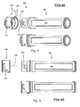
Figs. 1 and 2 disclose a syringe device known in the art, -
Fig. 3 discloses a medical delivery system according to the present invention, and -
Figs. 4 and5 disclose a container having two and three projections respectively, -
Figs. 6-12 disclose cross-sections of containers having two, three or four projections. -
Figs. 13a and 13b disclose an embodiment having axially extending indentations which during fastening are rotated into engagement with axially extending protrusions. -
Figs. 1 and 2 disclose asyringe device 100 which prior to filing of the present application has been marketed in Europe and the USA by the applicant and under the name "NovoPen® 4". Thesyringe device 100 comprises aproximal part 102 and adistal part 104. In use, theproximal part 102 forms part of a dose setting unit (not shown) comprising a piston rod (not shown) extending through a passage (not shown) of theproximal part 102. A centre axis of the piston rod coincides with the dottedline 106. In use thedistal part 104 defines acompartment 108 for accommodation of a reservoir (not shown) accommodating a medicament. Thedistal part 104 comprises tworidges 110 one on each side of the distal part which are used to secure thedistal part 104 to theproximal part 102, by advancing theridges 110 into matchingtracks 112 of theproximal part 102. The tracks are defined on aninner surface 114 of theproximal part 102. -
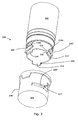
Fig. 3 discloses amedical delivery system 200 comprising acontainer 202 and a dosing assembly 204 (for simplicity reasons only a part of the dosing assembly is disclosed). Thecontainer 202 defines twoprojections 206',206" which are adapted to engage matchinggrooves 208',208" of thedosing assembly 204. When theprojections 206',206" are advanced into thegrooves 208',208", the container and the dosing assembly may be rotated whereby the engagement between a distal facingsurface 210a of container and a proximal facingsurface 212" ofdosing assembly 204 causes the dosing assembly and the container to be pulled towards each other while performing a concurrent axial and rotational movement. The concurrent movement is caused by the slopingproximal facing surface 212" which initially engages distal facingsurface 210a and subsequently distal facingsurface 210b. - The medical delivery system comprises three axially extending
protrusions 214, which in a first embodiment ofFig. 3 define rotational stoppingsurfaces 216 which during the concurrent movement are adapted to engage corresponding stopping surfaces (not shown) of the dosing assembly so as to prevent further rotational movement. - In a second embodiment of
Fig. 3 theprotrusions 214 define a first part of an axially extending coding mechanism which further comprises axially extending indentations (not shown) provided in the dosing assembly. - The
projections 206',206" comprises twoinclined surfaces 218 which prevents unintentional engagement between a projection and a groove e.g. in the case of a patient trying to fasten a container to a dosing assembly to which it cannot be fastened. Thus, should the user tilt the container and the dosing assembly (such that their longitudinal axes are not coincide but rather cross each other) whereby a single projection could be advanced into a groove, relative rotation between the container and the dosing assembly causes the projection to be forced out of the groove due to the inclined surfaces 218. -
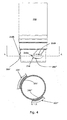
Fig. 4 discloses a cross-section and an elevational view of acontainer 202 which comprises twoprojections 206',206" provided in an asymmetrical pattern which is disclosed in the cross-sectional view ofFig. 4 and which comprises no lines of symmetry. The circumferential extent 205' of the first projection 206' is larger than thecircumferential extent 205" of thesecond projection 206". Due the asymmetry the container can only be fastened to a matching dosing assembly when the container is positioned in one single predetermined rotational position relative to the dosing assembly. -
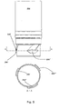
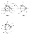
Fig. 5 discloses a cross-section and an elevational view of acontainer 202 having threeprojections 206',206",206"'. The projections define no lines of symmetry and the circumferential extent of the first projection 206' is larger than the circumferential extent of thethird projection 206"' which again is larger than the circumferential extent of thesecond projection 206". -
Figs. 6-8 disclose three containers each of which comprises threeprojections 206',206",206"'. InFig. 6 the angle between any two projections (about a centre axis 220) is 120 degrees and the projections have identical shapes. The cross section of the container defines three lines ofsymmetry 222. InFig. 7 the first andsecond projection 206',206" have identical shapes whereas the shape of thethird projection 206"' is different from the first and second projection. Again the angle between the any two projections is 120 degrees and the container defines one line ofsymmetry 222. In the third embodiment the first projection 206' is larger than thesecond projection 206" which is larger than thethird projection 206"' and thus the cross section defines no line of symmetry. - The projections may define a
centre point 224 as disclosed in relation toFig. 8 . The centre point may be defined as the centre of inertia of the projections and inFig. 8 the angle between any of the centre points about thecentre axis 220 is 120 degrees and thus different from 180 degrees. - The container of
Fig. 9 comprises fourprojections 206',206",206"',206"" rotationally spaced by 90 degrees. As the projections furthermore have identical shapes the cross-section of the container defines four lines ofsymmetry 222. The container ofFig. 10 comprises twoprojections 206',206" and thus define two lines of symmetry. - In
Fig. 11 the container comprises threeidentical projections 206',206",206"' and defines one line of symmetry. Moreover, the single line of symmetry extend through one of the projections. InFig. 12 the position of one of the projections is changed relative to the container ofFig. 11 whereby the container defines no lines of symmetry. - The
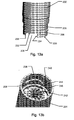
container 202 ofFig. 13a is adapted to be fastened to thedosing assembly 204 ofFig. 13b , through a combined rotational and axial movement. Thecontainer 202 defines aradially extending projection 206 which extends from asidewall 226 of thecontainer 202, and anindentation 228 extending axially into thesidewall 226, in a distal direction from theproximal end surface 230. Theaxially extending indentation 228 defines abottom surface 232, astop surface 234 and aninclined surface 236. Thedosing assembly 204 defines agroove 208 for receiving theprojection 206 during fastening of thecontainer 202 to thedosing assembly 204. In the embodiment ofFig. 13b thegroove 208 is defined by aprojection 238 extending radially out from asidewall 240 of thedosing assembly 204 and in the direction of the centre of thedosing assembly 204. Theinclined surface 236 is shaped so as to allow anaxially extending protrusion 242 of thedosing assembly 204 to be moved into (and thus received by) theaxially extending indentation 228 of thecontainer 202. Thestop surface 234 of theindentation 228 is adapted to engage acorresponding stop surface 244 of theprotrusion 242 of thedosing assembly 204 so as to prevent further relative rotation between thecontainer 202 and thedosing assembly 204. Abutment between the two stop surfaces 234,244 provides the user with a tactile indication of the fact that thecontainer 202 is fastened to thedosing assembly 204. - The
projection 238 of the dosing assembly is shaped such that thegroove 208 does not define a stop surface and thus a dosing assembly similar to that ofFig. 13b but without theaxially extending protrusion 242, will not provide the user with a tactile indication of the fact that thecontainer 202 is fastened to such adosing assembly 204. Accordingly, thecontainer 202 ofFig. 13a cannot be fastened to adosing assembly 204 similar to that ofFig. 13b but not defining theprotrusion 242. This prevents acontainer 202 from being fastened to adosing assembly 204 of that configuration. - Containers similar to that of
Fig. 13a but not defining theaxially extending indentation 228 may take two forms. A first form wherein theproximal end surface 230 is defined at the same axial level as thesurface 230 inFig. 13a , and a second wherein theproximal end surface 230 is defined at the same axial level as thebottom surface 232 inFig. 13a . The difference between the first and the second forms is the distance betweensurface 230 and theprojection 206. - A
container 202 of the first form i.e. wherein theproximal end surface 230 is defined at the same axial level as theproximal end surface 230 ofFig. 13a and withoutindentations 228, cannot be fastened to thedosing assembly 204 ofFig. 13b as theproximal end surface 230 of thecontainer 202 will abut a distal facingsurface 246 of theprotrusion 242, whereby theprojection 206 cannot be received in thegroove 208 or can only be moved partly into thegroove 208 i.e. in a way insufficient to fasten thecontainer 202 to thedosing assembly 204. - A
container 202 of the second form i.e. wherein theproximal end surface 230 is defined at the same axial level thebottom surface 232 inFig. 13a and not definingindentations 228, cannot be fastened to adosing assembly 204 not defining the axially extending protrusion(s) 242 as the user is not provided with the tactile indication allowing him to determine when thecontainer 202 is fastened to thedosing assembly 204 and vice versa. Accordingly, the user will continue the relative rotation between thecontainer 202 and thedosing assembly 204, whereby theprojection 206 will be moved out of thegroove 208, such that thecontainer 202 is not fastened to thedosing assembly 204. - It will be appreciated from the above, that the embodiment of
Fig. 13a and 13b increases user safety as acontainer 202 not designated to be used in connection with apredetermined dosing assembly 204, cannot be fastened to such adosing assembly 204. Thus, the user is prohibited from attaching acontainer 202 with a wrong medicament or a correct medicament in a wrong concentration to adosing assembly 204, and thereby prevented from ejecting such a medicament.
Claims (21)
- A medical delivery system (200) comprising:- a container (202) adapted to contain a medicament in a chamber defined by the container (202) and a slidably arranged piston which is moveable along an axis in a distal direction towards an outlet so as to reduce the volume of the chamber and expel the medicament through the outlet;- a dosing assembly (204) adapted to be fastened to the container (202), so as to allow a driver of the dosing assembly (204) to move the piston of the container (202) in the distal direction;- wherein the dosing assembly (204) defines a first fastening means (208,208',208") which during fastening of the container (202) to the dosing assembly (204) engages a second fastening means (206,206',206",206"') of the container (202) whereby the container (202) is fastened to the dosing assembly (204) through a predetermined movement defined by at least one of the first and the second fastening means (208,208',208",206, 206',206",206"'), the predetermined movement being less than one revolution; and- wherein a sidewall of one of the first and second fastening means (208,208',208",206, 206',206",206"') defines at least two projections (206,206',206",206"') extending in a radial direction, each of the at least two projections being adapted to engage a corresponding groove (208,208',208") defined in a sidewall of the other one of the first and second fastening means;- characterized in that at least one of the first and second fastening means (208,208',208",206,206',206",206"') defines an asymmetrical pattern in a plane transverse to said axis.
- A medical delivery system according to claim 1, wherein each of the first and second fastening means (208,208',208",206,206', 206",206"') defines an asymmetrical pattern in the plane transverse to said axis.
- A medical delivery system according to claim 1 or 2, wherein one of the first and second fastening means (208,208',208",206,206',206",206"') defines less than two lines of symmetry in the plane transverse to said axis.
- A medical delivery system according to any of the preceding claims, wherein at least one of the first and second fastening means (208,208',208",206,206',206",206"') defines no line of symmetry in the plane transverse to said axis.
- A medical delivery system according to any of the preceding claims, wherein the plane extends through all of the at least two projections (206,206',206",206"') or the at least two grooves (208,208',208").
- A medical delivery system according to any of the preceding claims, wherein each of the at least two projections (206,206',206",206"') or grooves (208,208',208") defines a centre point, and wherein the angle between any two centre points about said axis, is different from 180 degrees.
- A medical delivery system according to any of the preceding claims, wherein the circumferential extent of two or more of the at least two projections (206,206',206",206"') or grooves (208,208',208") are different.
- A medical delivery system according to any of the preceding claims, wherein one or more of the at least two projections (206,206',206",206"') or grooves (208,208',208") define an inclined surface (218).
- A medical delivery system according to any of the preceding claims, further comprising an axially extending coding mechanism (214,228,242) defined by a proximal end surface (230) of the container (202) and a corresponding distal end surface of the dosing assembly (204), the proximal end surface (230) of the container (202) defining one or more axially extending protrusions (214) and/or indentations (228) which during fastening of the container (202) to the dosing assembly (204) cooperate with matching one or more protrusions (242) and/or indentations of a distal facing coding surface of the dosing assembly (204) so as to prevent said predetermined movement unless each of the distal and proximal facing surfaces define one or more predetermined protrusions and/or indentations selected from a predetermined group of protrusions and/or indentations.
- A medical delivery system according to any of the preceding claims, wherein the container (202) comprises a cartridge holder defining said second fastening means (208,208',208",206,206',206",206"'), and a cartridge defining said chamber, and wherein the cartridge is non-detachably attached to the cartridge holder.
- A medical delivery system according to any of the preceding claims, wherein at least a part of said predetermined movement is a concurrent axial and rotational movement.
- A medical delivery system according to claim 11, wherein the first and/or second fastening means (208,208',208",206,206',206",206"') is/are adapted to prevent a part of the axial and/or rotational movement of the predetermined movement, so as to prevent coupling of the container (202) to the dosing assembly (204) unless each of the first and second fastening means (208,208',208",206,206',206",206"') defines a predetermined coding geometry.
- A medical delivery system according to claim 12, wherein the coding geometry of the first and/or second fastening means (208,208',208",206,206',206",206"') is defined by at least one of: a circumferential extent of the first and second fastening means, an axial extent of the first and second fastening means , a radial extent of the first and second fastening means and the circumferential position of the first and second fastening means.
- A medical delivery system according to any of the preceding claims, comprising:- a first container (202) according to any of the preceding claims adapted to be fastened to a first dosing assembly (204) according to any of the preceding claims; and- a second container (202) according to any of the preceding claims adapted to be fastened to a second dosing assembly (204) according to any of the preceding claims; andwherein at least two of- the first fastening means (208,208',208") of the first dosing assembly (204),- the first fastening means (208,208',208") of the second dosing assembly (204),- the second fastening means (206,206',206",206"') of the first container (202), and- the second fastening means (206,206',206",206"') of the second container (202),are adapted to prevent the first dosing assembly (204) and second container (202) from being fastened to each other, and to prevent the second dosing assembly (204) and the first container (202) from being fastened to each other.
- A medical delivery system according to claim 14, wherein the predetermined movement required for coupling and uncoupling the first container (202) to the first dosing assembly (204) and for coupling the second container (202) to the second dosing assembly (204) are essentially the same.
- A container (202) for use in a medical delivery system (200) according to any of claims 1-15, the container (202) being adapted to contain a medicament in a chamber defined by the container (202) and a slidably arranged piston which is moveable along an axis in a distal direction towards an outlet so as to reduce the volume of the chamber and expel the medicament through the outlet, the container (202) comprising second fastening means (206,206', 206",206"') adapted to engage first fastening means (208,208',208") of a dosing assembly (204), the second fastening means (206,206', 206",206"') defining either at least two projections (206,206',206",206"') extending in a radial direction or at least two grooves defined in a sidewall of the second fastening means (206,206', 206",206"'), characterized in that the second fastening means (206,206', 206"') defines an asymmetrical pattern in a plane transverse to said axis.
- A container according to claim 16, wherein the second fastening means (206,206',206",206"') defines no line of symmetry in the plane transverse to said axis.
- A container according to any of the claims 16 or 17, wherein the circumferential extent of two or more of the at least two projections (206,206',206",206"') or grooves are different.
- A container according to any of the claims 16-18, wherein a proximal end surface (230) of the container (202) defines one or more axially extending protrusions (214) and/or indentations (228).
- A container according to any of the claims 16-19, wherein the container (202) comprises a cartridge holder for holding a cartridge and wherein the second fastening means (206,206', 206",206"') are defined by or attached to the cartridge holder.
- A dosing assembly (204) suitable for use in a medical delivery system (200) according to any of claims 1-15.
Priority Applications (1)
| Application Number | Priority Date | Filing Date | Title |
|---|---|---|---|
| EP07787550A EP2043708B1 (en) | 2006-07-15 | 2007-07-15 | Medical delivery system with asymmetrical coding means |
Applications Claiming Priority (4)
| Application Number | Priority Date | Filing Date | Title |
|---|---|---|---|
| EP06014770 | 2006-07-15 | ||
| EP07000430 | 2007-01-10 | ||
| EP07787550A EP2043708B1 (en) | 2006-07-15 | 2007-07-15 | Medical delivery system with asymmetrical coding means |
| PCT/EP2007/057282 WO2008009645A1 (en) | 2006-07-15 | 2007-07-15 | Medical delivery system with asymmetrical coding means |
Publications (2)
| Publication Number | Publication Date |
|---|---|
| EP2043708A1 EP2043708A1 (en) | 2009-04-08 |
| EP2043708B1 true EP2043708B1 (en) | 2010-12-29 |
Family
ID=38437004
Family Applications (1)
| Application Number | Title | Priority Date | Filing Date |
|---|---|---|---|
| EP07787550A Active EP2043708B1 (en) | 2006-07-15 | 2007-07-15 | Medical delivery system with asymmetrical coding means |
Country Status (6)
| Country | Link |
|---|---|
| US (1) | US8613731B2 (en) |
| EP (1) | EP2043708B1 (en) |
| JP (1) | JP2009543629A (en) |
| AT (1) | ATE493161T1 (en) |
| DE (1) | DE602007011620D1 (en) |
| WO (1) | WO2008009645A1 (en) |
Cited By (2)
| Publication number | Priority date | Publication date | Assignee | Title |
|---|---|---|---|---|
| US10765811B2 (en) | 2014-12-08 | 2020-09-08 | Genentech, Inc. | Versatile syringe platform |
| KR102274078B1 (en) | 2014-10-28 | 2021-07-09 | 바이엘 헬쓰케어 엘엘씨 | Self-orienting syringe and syringe interface |
Families Citing this family (38)
| Publication number | Priority date | Publication date | Assignee | Title |
|---|---|---|---|---|
| DE60213253T2 (en) * | 2001-08-27 | 2007-07-26 | Novo Nordisk A/S | A CARTRIDGE AND A MEDICAL DELIVERY SYSTEM THAT SUCH AS A CARTRIDGE |
| JP2010512817A (en) * | 2006-12-15 | 2010-04-30 | ノボ・ノルデイスク・エー/エス | Medical delivery system comprising a container and a dosing assembly having a radially moving fastening means |
| JP5213875B2 (en) * | 2006-12-21 | 2013-06-19 | ノボ・ノルデイスク・エー/エス | Injection device |
| CA2724641C (en) | 2008-05-20 | 2020-03-24 | Avant Medical Corp. | Autoinjector system |
| US8052645B2 (en) | 2008-07-23 | 2011-11-08 | Avant Medical Corp. | System and method for an injection using a syringe needle |
| WO2010000721A1 (en) | 2008-06-30 | 2010-01-07 | Novo Nordisk A/S | Anti-human interleukin-20 antibodies |
| EP2307079B1 (en) | 2008-07-15 | 2015-07-22 | SHL Group AB | Medicament delivery device |
| US8205917B2 (en) | 2008-12-12 | 2012-06-26 | Kimberly-Clark Worldwide, Inc. | Quick connect fitting for respiratory devices |
| US8454956B2 (en) | 2009-08-31 | 2013-06-04 | National Cheng Kung University | Methods for treating rheumatoid arthritis and osteoporosis with anti-IL-20 antibodies |
| US9381304B2 (en) * | 2010-04-23 | 2016-07-05 | Sanofi-Aventis Deutschland Gmbh | Cartridge holder and alignment interface |
| CA2796790A1 (en) | 2010-04-23 | 2011-10-27 | Sanofi-Aventis Deutschland Gmbh | Coded fastener assembly |
| WO2011131779A1 (en) * | 2010-04-23 | 2011-10-27 | Sanofi-Aventis Deutschland Gmbh | Drug delivery device and drug reservoir with mechanical coding mechanism |
| BR112012027109B1 (en) | 2010-04-23 | 2020-06-02 | Sanofi-Aventis Deutschland Gmbh | ENCODED CARTRIDGE SET |
| GB2476146B (en) * | 2010-11-23 | 2011-12-14 | Cpp Rowley Ltd | Pharmaceutical product storage and delivery system |
| CA2815946A1 (en) * | 2010-12-09 | 2012-06-14 | Sanofi-Aventis Deutschland Gmbh | Drug delivery device |
| LT2699293T (en) * | 2011-04-20 | 2019-04-25 | Amgen Inc. | Autoinjector apparatus |
| CN104582760A (en) * | 2012-01-25 | 2015-04-29 | 诺沃—诺迪斯克有限公司 | Drug delivery device with cartridge fixation feature |
| EP2814560B8 (en) | 2012-02-13 | 2020-06-17 | Yukon Medical, LLC | Connector |
| AU2013224349A1 (en) | 2012-02-24 | 2014-08-21 | Novo Nordisk A/S | Drug delivery device with front loading feature |
| US9221904B2 (en) | 2012-07-19 | 2015-12-29 | National Cheng Kung University | Treatment of osteoarthritis using IL-20 antagonists |
| US8603470B1 (en) | 2012-08-07 | 2013-12-10 | National Cheng Kung University | Use of IL-20 antagonists for treating liver diseases |
| US8852588B2 (en) | 2012-08-07 | 2014-10-07 | National Cheng Kung University | Treating allergic airway disorders using anti-IL-20 receptor antibodies |
| US10207096B2 (en) | 2013-02-27 | 2019-02-19 | Fresenius Medical Care Holdings, Inc. | Fluid line connectors |
| US10492990B2 (en) | 2013-03-15 | 2019-12-03 | Amgen Inc. | Drug cassette, autoinjector, and autoinjector system |
| WO2015061690A1 (en) | 2013-10-24 | 2015-04-30 | Trustees Of Boston University | Infusion system for preventing mischanneling of multiple medicaments |
| DE102013018639A1 (en) | 2013-11-06 | 2014-07-24 | Fresenius Medical Care Deutschland Gmbh | Connector for connecting bag and hose system for providing e.g. medical solution during extraporal blood treatment for patient, has cone only opening sealing element when projection of one part is inserted in retainer of other part |
| BR112017008878B1 (en) * | 2014-10-28 | 2022-10-11 | Bayer Healthcare Llc | PRESSURE SHIRT |
| US9199033B1 (en) | 2014-10-28 | 2015-12-01 | Bayer Healthcare Llc | Self-orienting syringe and syringe interface |
| EP3212256A4 (en) | 2014-10-28 | 2018-07-18 | Bayer HealthCare LLC | Self-orienting pressure jacket and pressure jacket-to-injector interface |
| JP7125204B2 (en) | 2015-07-08 | 2022-08-24 | トラスティーズ オブ ボストン ユニバーシティ | Infusion system and its components |
| CN108472433B (en) | 2015-11-13 | 2021-12-14 | 拜耳医药保健有限公司 | Nested syringe assembly |
| BR112019013985A2 (en) | 2017-01-06 | 2020-03-03 | Trustees Of Boston University | INFUSION SYSTEM AND COMPONENTS OF THE SAME |
| US11191893B2 (en) | 2018-01-31 | 2021-12-07 | Bayer Healthcare Llc | System and method for syringe engagement with injector |
| KR102182282B1 (en) * | 2019-02-11 | 2020-11-24 | (주)풍림파마텍 | hub for injector with rewind protect structure |
| WO2021011699A1 (en) | 2019-07-16 | 2021-01-21 | Beta Bionics, Inc. | Ambulatory device and components thereof |
| MX2022007057A (en) * | 2019-12-11 | 2022-07-11 | Sanofi Sa | Electronic module and modular system for a drug delivery device. |
| US11278661B2 (en) | 2020-03-10 | 2022-03-22 | Beta Bionics, Inc. | Infusion system and components thereof |
| CN117177788A (en) * | 2021-05-03 | 2023-12-05 | 赛诺菲 | Housing part for an injection device |
Family Cites Families (94)
| Publication number | Priority date | Publication date | Assignee | Title |
|---|---|---|---|---|
| US1594493A (en) | 1922-09-16 | 1926-08-03 | Brown Henry Kinsey | Self-positioning ampul and syringe |
| GB301961A (en) | 1927-09-10 | 1928-12-10 | Mendel Nevin | Improvements in and relating to hypodermic syringes |
| US2020828A (en) | 1933-06-12 | 1935-11-12 | Novocol Chemical Mfg Co Inc | Hypodermic syringe and closure cap for containers |
| US2707466A (en) | 1951-07-18 | 1955-05-03 | Cook Waite Lab Inc | Hypodermic syringe |
| CH315980A (en) | 1953-11-07 | 1956-09-15 | Merk Hans | Dismountable gantry crane |
| US2880723A (en) | 1954-02-09 | 1959-04-07 | Becton Dickinson Co | Syringe assembly |
| US2818864A (en) | 1955-11-14 | 1958-01-07 | Adapto Inc | Guide cap |
| US3021840A (en) | 1957-04-17 | 1962-02-20 | Baxter Don Inc | Portable anesthesia apparatus |
| US2865372A (en) | 1957-11-18 | 1958-12-23 | Pfizer & Co C | Hypodermic syringe |
| US2888924A (en) | 1958-02-25 | 1959-06-02 | Russell P Dunmire | Hypodermic syringes |
| US3130742A (en) | 1961-08-01 | 1964-04-28 | Crane Co | Combined safety relief valve and conduit |
| US3130724A (en) | 1962-05-07 | 1964-04-28 | Roehr Products Company Inc | Syringe structure |
| US3170667A (en) | 1963-11-04 | 1965-02-23 | Crawford Fitting Co | Quick connect system |
| US3336924A (en) | 1964-02-20 | 1967-08-22 | Sarnoff | Two compartment syringe package |
| US3375825A (en) | 1965-09-02 | 1968-04-02 | Becton Dickinson Co | Prefilled syringe |
| US3537345A (en) | 1968-01-18 | 1970-11-03 | Ppg Industries Inc | Glass cutting apparatus |
| DE1814466A1 (en) | 1968-12-13 | 1970-06-25 | Hoechst Ag | Disposable syringe |
| GB1385670A (en) | 1970-11-01 | 1975-02-26 | Cyprane Ltd | Anaesthesia machines |
| DE2137405A1 (en) | 1971-07-26 | 1973-02-08 | Etimex Kunststoff | SPRAY FRAME |
| US3820652A (en) | 1972-11-14 | 1974-06-28 | T Thackston | Packaged syringe construction |
| DE2315367A1 (en) | 1973-03-28 | 1974-10-17 | Hoechst Ag | SINGLE USE INJECTION SYRINGE |
| US3895633A (en) | 1973-09-27 | 1975-07-22 | Survival Technology | Large capacity syringe |
| US3989044A (en) | 1975-08-11 | 1976-11-02 | Warner-Lambert Company | Syringe |
| DE2629557B2 (en) | 1976-07-01 | 1980-05-14 | Paul E. Dr.Med. 8000 Muenchen Doerr | Disposable injection syringe |
| USRE31873F1 (en) | 1976-09-08 | 1988-11-15 | Venous catheter device | |
| US4150673A (en) | 1977-02-03 | 1979-04-24 | Pharmachem Corporation | Coded entry system for blood bag |
| US4089432A (en) | 1977-05-06 | 1978-05-16 | The Upjohn Company | Vial and closure |
| US4280723A (en) | 1978-07-26 | 1981-07-28 | Moldestad Jon P | Safety device for hose connections |
| USRE31878E (en) | 1981-03-27 | 1985-05-07 | Allied Corporation | Disc brake having a piston retraction assembly |
| US4490142A (en) | 1983-08-22 | 1984-12-25 | Silvern Rubin D | Carpule syringe with rapidly acting mechanism for controllably _positively retaining the hub of a hypodermic needle |
| US4592745A (en) | 1984-02-29 | 1986-06-03 | Novo Industri A/S | Dispenser |
| US4619651A (en) | 1984-04-16 | 1986-10-28 | Kopfer Rudolph J | Anti-aerosoling drug reconstitution device |
| FR2563436B1 (en) | 1984-04-26 | 1987-06-12 | Taddei Andre | STER ILE INJECTION SYRINGE DEVICE, ESPECIALLY FOR DENTISTS |
| US4619640A (en) * | 1984-08-17 | 1986-10-28 | Potolsky Abraham I | Blood transfusion connector assembly |
| JPS61104299A (en) | 1984-10-26 | 1986-05-22 | 日揮株式会社 | Method of disposing radioactive decontaminated waste liquor |
| US4685314A (en) | 1985-03-06 | 1987-08-11 | University Of Cincinnati | Device and method for preventing transfusion of incompatible blood |
| GB8509301D0 (en) | 1985-04-11 | 1985-05-15 | Clinical Products Dev Ltd | Device for surgical procedures |
| DE3676769D1 (en) | 1985-07-31 | 1991-02-14 | Kawasumi Lab Inc | COUPLING FOR PLASMAPHERESIS BAG. |
| JPH01500165A (en) | 1986-07-11 | 1989-01-26 | アルツナイミツテル ゲ−エムベ−ハ− アポテ−カ フエツタ− ウント コンパニ ラ−ヴエンスブルク | medical syringe |
| DK177187A (en) | 1987-04-07 | 1988-10-08 | Dcp Af 1988 As | DOSING UNIT FOR DOSING A NUMBER OF MEASURED QUANTITIES OF A FLUID, SUCH AS INSULIN, FROM A GLASS AMPULA |
| US4768568A (en) | 1987-07-07 | 1988-09-06 | Survival Technology, Inc. | Hazardous material vial apparatus providing expansible sealed and filter vented chambers |
| US4740205A (en) | 1987-07-23 | 1988-04-26 | Leilani Seltzer | Disposable needle system |
| US4976701A (en) | 1987-09-25 | 1990-12-11 | Nordisk Gentofte A/S | Injection apparatus |
| US4834717A (en) | 1987-09-25 | 1989-05-30 | Habley Medical Technology Corporation | Disposable, pre-sterilizable syringe for a pre-filled medication cartridge |
| US4948000A (en) | 1987-11-20 | 1990-08-14 | Grabenkort Richard W | Container shrouds |
| US4973318A (en) | 1988-02-10 | 1990-11-27 | D.C.P. Af 1988 A/S | Disposable syringe |
| US5205833A (en) | 1988-02-22 | 1993-04-27 | Harsh Don J | Device for removing hypodermic needles from syringe barrels |
| US5244465A (en) | 1988-10-19 | 1993-09-14 | Byk Gulden Lomberg Chemische Fabrik Gmbh | Reusable injection device for distributing a preselected dose |
| DK68789A (en) | 1989-02-14 | 1990-08-15 | Novo Nordisk As | injector |
| US5269317A (en) | 1989-06-08 | 1993-12-14 | Bennett Scientific, Inc. | Intravenous blood sampling apparatus |
| US4944736A (en) | 1989-07-05 | 1990-07-31 | Holtz Leonard J | Adaptor cap for centering, sealing, and holding a syringe to a bottle |
| US5084017A (en) | 1989-10-10 | 1992-01-28 | John Maffetone | Self disabling, single use, hypodermic syringe |
| US4990142A (en) | 1989-10-23 | 1991-02-05 | Gte Products Corporation | Hypodermic syringe |
| US5002537A (en) | 1989-10-23 | 1991-03-26 | Gte Products Corporation | Hypodermic syringe |
| US5226896A (en) | 1990-04-04 | 1993-07-13 | Eli Lilly And Company | Dose indicating injection pen |
| DE69110290T2 (en) | 1990-09-21 | 1995-10-19 | Novo Nordisk As | ADAPTER. |
| DK228290D0 (en) | 1990-09-21 | 1990-09-21 | Novo Nordisk As | AND INJECTION UNIT |
| US5286258A (en) * | 1991-03-08 | 1994-02-15 | Habley Medical Technology Corporation | Multipharmaceutical delivery system |
| JP3258323B2 (en) | 1991-11-29 | 2002-02-18 | ノボ ノルディスク アクティーゼルスカブ | Pen-shaped syringe |
| GB9226423D0 (en) | 1992-12-18 | 1993-02-10 | Sams Bernard | Incrementing mechanisms |
| US5451214A (en) | 1993-03-22 | 1995-09-19 | Hajishoreh; Kaveh-Karimi | Syringe apparatus |
| US5478323A (en) * | 1993-04-02 | 1995-12-26 | Eli Lilly And Company | Manifold for injection apparatus |
| US5584815A (en) | 1993-04-02 | 1996-12-17 | Eli Lilly And Company | Multi-cartridge medication injection device |
| US5498253A (en) | 1993-11-23 | 1996-03-12 | Baxter International Inc. | Port adaptor and protector and container having same |
| DE4419235C2 (en) | 1994-06-01 | 1999-03-11 | Thomas Braeger | Hypodermic syringe with a receptacle |
| CA2213682C (en) | 1995-03-07 | 2009-10-06 | Eli Lilly And Company | Recyclable medication dispensing device |
| US5786584A (en) | 1995-09-06 | 1998-07-28 | Eli Lilly And Company | Vial and cartridge reading device providing audio feedback for a blood glucose monitoring system |
| IT1281248B1 (en) | 1995-11-16 | 1998-02-17 | Pier Luigi Delvigo | MEDICAL SAFETY DEVICE FOR TRANSFUSIONS. |
| US5873861A (en) | 1996-11-12 | 1999-02-23 | Medrad, Inc. | Plunger systems |
| JPH10290842A (en) | 1997-04-21 | 1998-11-04 | Aki Uebu Agency:Kk | Infusion type identifying port and infusion type identifying communication tool |
| AUPO723997A0 (en) | 1997-06-10 | 1997-07-03 | Astra Pharmaceuticals Pty Ltd | Prefilled container |
| US5957896A (en) * | 1997-08-11 | 1999-09-28 | Becton, Dickinson And Company | Medication delivery pen |
| WO1999016485A1 (en) * | 1997-09-29 | 1999-04-08 | Becton Dickinson And Company | Injection device and drug cartridge for preventing cross-use of the device and drug cartridge |
| US5954700A (en) | 1998-01-13 | 1999-09-21 | Minimed Inc. | Medication cartridge for an electronic pen-type injector, or the like, and method of making the same |
| CA2236049C (en) | 1998-04-27 | 2006-07-25 | Computer Controlled Syringe Inc. | Syringe with detachable syringe barrel |
| ATE251478T1 (en) | 1998-07-08 | 2003-10-15 | Novo Nordisk As | A DISCHARGE DEVICE AND ASSOCIATED CARTRIDGE |
| WO2000002605A1 (en) | 1998-07-08 | 2000-01-20 | Novo Nordisk A/S | A medical delivery device and a cartridge assembly for use in the same |
| IT1303584B1 (en) | 1998-12-15 | 2000-11-14 | Achim Berlovan | KIT OF SYRINGE AND COORDINATED NEEDLES, FOR INJECTIONS, ESPECIALLY DENTAL ANESTHESIA. |
| DE19900792C1 (en) | 1999-01-12 | 2000-06-15 | Disetronic Licensing Ag | Injection unit forming part of e.g. pen-type self-injection syringe has continuous dosing stop in spiral form with constant pitch ensuring close fine control and accuracy in use |
| US6197040B1 (en) | 1999-02-23 | 2001-03-06 | Lifescan, Inc. | Lancing device having a releasable connector |
| US7077828B2 (en) | 1999-03-05 | 2006-07-18 | Roche Diagnostics Gmbh | Device for withdrawing blood for diagnostic applications |
| US6652489B2 (en) | 2000-02-07 | 2003-11-25 | Medrad, Inc. | Front-loading medical injector and syringes, syringe interfaces, syringe adapters and syringe plungers for use therewith |
| GB0007071D0 (en) | 2000-03-24 | 2000-05-17 | Sams Bernard | One-way clutch mechanisms and injector devices |
| WO2002030490A2 (en) | 2000-10-10 | 2002-04-18 | Dentsply International Inc. | Fluid material dispensing syringe |
| US7316679B2 (en) | 2001-01-22 | 2008-01-08 | Venetec International, Inc. | Medical device connector fitting |
| EP2258425B1 (en) | 2001-05-16 | 2013-01-30 | Eli Lilly and Company | Medication injector apparatus |
| DE20110690U1 (en) | 2001-06-27 | 2001-09-13 | Spyra Heinrich | Protection against confusion to prevent an injection aid from being fitted with the wrong medication ampoule |
| DE10163328B4 (en) | 2001-07-30 | 2005-08-11 | Tecpharma Licensing Ag | Administration device with anti-rotation device |
| DE10163327A1 (en) | 2001-07-30 | 2003-02-27 | Disetronic Licensing Ag | Reservoir module with piston rod |
| DE60213253T2 (en) | 2001-08-27 | 2007-07-26 | Novo Nordisk A/S | A CARTRIDGE AND A MEDICAL DELIVERY SYSTEM THAT SUCH AS A CARTRIDGE |
| GB2410305B (en) | 2001-09-04 | 2005-12-07 | Clinical Product Dev Ltd | Couplings for medical fluid delivery systems |
| DE10147973A1 (en) * | 2001-09-28 | 2003-04-17 | Disetronic Licensing Ag | ampoules recognition |
| DE102004063644A1 (en) | 2004-12-31 | 2006-07-20 | Tecpharma Licensing Ag | Device for the dosed administration of a fluid product with torsion spring drive |
| JP2009543630A (en) | 2006-07-15 | 2009-12-10 | ノボ・ノルデイスク・エー/エス | Drug delivery system with rotatable coding element |
-
2007
- 2007-07-15 EP EP07787550A patent/EP2043708B1/en active Active
- 2007-07-15 WO PCT/EP2007/057282 patent/WO2008009645A1/en active Application Filing
- 2007-07-15 DE DE602007011620T patent/DE602007011620D1/en active Active
- 2007-07-15 AT AT07787550T patent/ATE493161T1/en not_active IP Right Cessation
- 2007-07-15 US US12/373,339 patent/US8613731B2/en active Active
- 2007-07-15 JP JP2009519960A patent/JP2009543629A/en not_active Withdrawn
Cited By (3)
| Publication number | Priority date | Publication date | Assignee | Title |
|---|---|---|---|---|
| KR102274078B1 (en) | 2014-10-28 | 2021-07-09 | 바이엘 헬쓰케어 엘엘씨 | Self-orienting syringe and syringe interface |
| US10765811B2 (en) | 2014-12-08 | 2020-09-08 | Genentech, Inc. | Versatile syringe platform |
| US11633545B2 (en) | 2014-12-08 | 2023-04-25 | Genentech, Inc. | Versatile syringe platform |
Also Published As
| Publication number | Publication date |
|---|---|
| EP2043708A1 (en) | 2009-04-08 |
| US8613731B2 (en) | 2013-12-24 |
| US20090281505A1 (en) | 2009-11-12 |
| JP2009543629A (en) | 2009-12-10 |
| ATE493161T1 (en) | 2011-01-15 |
| WO2008009645A1 (en) | 2008-01-24 |
| DE602007011620D1 (en) | 2011-02-10 |
Similar Documents
| Publication | Publication Date | Title |
|---|---|---|
| EP2043708B1 (en) | Medical delivery system with asymmetrical coding means | |
| US8632506B2 (en) | Medical delivery system comprising a coding mechanism | |
| US9050397B2 (en) | Medical delivery system with a rotatable coding element | |
| EP2091598B1 (en) | A medical delivery system comprising a container and a dosing assembly with radially moving fastening means | |
| US9289558B2 (en) | Medical delivery system comprising locking ring with L-shaped grooves | |
| EP2091600B1 (en) | A syringe device | |
| EP2059285B1 (en) | A medical delivery system adapted to be locked axially and unlocked rotationally | |
| US20100042054A1 (en) | Medical Delivery System Comprising a Coding Mechanism Between Dosing Assembly and Medicament Container | |
| CN101489608A (en) | Medical delivery system with asymmetrical coding means |
Legal Events
| Date | Code | Title | Description |
|---|---|---|---|
| PUAI | Public reference made under article 153(3) epc to a published international application that has entered the european phase |
Free format text: ORIGINAL CODE: 0009012 |
|
| 17P | Request for examination filed |
Effective date: 20090216 |
|
| AK | Designated contracting states |
Kind code of ref document: A1 Designated state(s): AT BE BG CH CY CZ DE DK EE ES FI FR GB GR HU IE IS IT LI LT LU LV MC MT NL PL PT RO SE SI SK TR |
|
| AX | Request for extension of the european patent |
Extension state: AL BA HR MK RS |
|
| 17Q | First examination report despatched |
Effective date: 20090819 |
|
| GRAP | Despatch of communication of intention to grant a patent |
Free format text: ORIGINAL CODE: EPIDOSNIGR1 |
|
| GRAS | Grant fee paid |
Free format text: ORIGINAL CODE: EPIDOSNIGR3 |
|
| GRAA | (expected) grant |
Free format text: ORIGINAL CODE: 0009210 |
|
| AK | Designated contracting states |
Kind code of ref document: B1 Designated state(s): AT BE BG CH CY CZ DE DK EE ES FI FR GB GR HU IE IS IT LI LT LU LV MC MT NL PL PT RO SE SI SK TR |
|
| REG | Reference to a national code |
Ref country code: GB Ref legal event code: FG4D |
|
| REG | Reference to a national code |
Ref country code: CH Ref legal event code: EP |
|
| REG | Reference to a national code |
Ref country code: IE Ref legal event code: FG4D |
|
| REF | Corresponds to: |
Ref document number: 602007011620 Country of ref document: DE Date of ref document: 20110210 Kind code of ref document: P |
|
| REG | Reference to a national code |
Ref country code: DE Ref legal event code: R096 Ref document number: 602007011620 Country of ref document: DE Effective date: 20110210 |
|
| REG | Reference to a national code |
Ref country code: NL Ref legal event code: VDEP Effective date: 20101229 |
|
| PG25 | Lapsed in a contracting state [announced via postgrant information from national office to epo] |
Ref country code: LT Free format text: LAPSE BECAUSE OF FAILURE TO SUBMIT A TRANSLATION OF THE DESCRIPTION OR TO PAY THE FEE WITHIN THE PRESCRIBED TIME-LIMIT Effective date: 20101229 |
|
| LTIE | Lt: invalidation of european patent or patent extension |
Effective date: 20101229 |
|
| PG25 | Lapsed in a contracting state [announced via postgrant information from national office to epo] |
Ref country code: FI Free format text: LAPSE BECAUSE OF FAILURE TO SUBMIT A TRANSLATION OF THE DESCRIPTION OR TO PAY THE FEE WITHIN THE PRESCRIBED TIME-LIMIT Effective date: 20101229 Ref country code: BG Free format text: LAPSE BECAUSE OF FAILURE TO SUBMIT A TRANSLATION OF THE DESCRIPTION OR TO PAY THE FEE WITHIN THE PRESCRIBED TIME-LIMIT Effective date: 20110329 Ref country code: CY Free format text: LAPSE BECAUSE OF FAILURE TO SUBMIT A TRANSLATION OF THE DESCRIPTION OR TO PAY THE FEE WITHIN THE PRESCRIBED TIME-LIMIT Effective date: 20101229 Ref country code: AT Free format text: LAPSE BECAUSE OF FAILURE TO SUBMIT A TRANSLATION OF THE DESCRIPTION OR TO PAY THE FEE WITHIN THE PRESCRIBED TIME-LIMIT Effective date: 20101229 Ref country code: SE Free format text: LAPSE BECAUSE OF FAILURE TO SUBMIT A TRANSLATION OF THE DESCRIPTION OR TO PAY THE FEE WITHIN THE PRESCRIBED TIME-LIMIT Effective date: 20101229 Ref country code: SI Free format text: LAPSE BECAUSE OF FAILURE TO SUBMIT A TRANSLATION OF THE DESCRIPTION OR TO PAY THE FEE WITHIN THE PRESCRIBED TIME-LIMIT Effective date: 20101229 Ref country code: LV Free format text: LAPSE BECAUSE OF FAILURE TO SUBMIT A TRANSLATION OF THE DESCRIPTION OR TO PAY THE FEE WITHIN THE PRESCRIBED TIME-LIMIT Effective date: 20101229 |
|
| PG25 | Lapsed in a contracting state [announced via postgrant information from national office to epo] |
Ref country code: PT Free format text: LAPSE BECAUSE OF FAILURE TO SUBMIT A TRANSLATION OF THE DESCRIPTION OR TO PAY THE FEE WITHIN THE PRESCRIBED TIME-LIMIT Effective date: 20110429 Ref country code: GR Free format text: LAPSE BECAUSE OF FAILURE TO SUBMIT A TRANSLATION OF THE DESCRIPTION OR TO PAY THE FEE WITHIN THE PRESCRIBED TIME-LIMIT Effective date: 20110330 Ref country code: BE Free format text: LAPSE BECAUSE OF FAILURE TO SUBMIT A TRANSLATION OF THE DESCRIPTION OR TO PAY THE FEE WITHIN THE PRESCRIBED TIME-LIMIT Effective date: 20101229 Ref country code: IS Free format text: LAPSE BECAUSE OF FAILURE TO SUBMIT A TRANSLATION OF THE DESCRIPTION OR TO PAY THE FEE WITHIN THE PRESCRIBED TIME-LIMIT Effective date: 20110429 Ref country code: EE Free format text: LAPSE BECAUSE OF FAILURE TO SUBMIT A TRANSLATION OF THE DESCRIPTION OR TO PAY THE FEE WITHIN THE PRESCRIBED TIME-LIMIT Effective date: 20101229 Ref country code: CZ Free format text: LAPSE BECAUSE OF FAILURE TO SUBMIT A TRANSLATION OF THE DESCRIPTION OR TO PAY THE FEE WITHIN THE PRESCRIBED TIME-LIMIT Effective date: 20101229 Ref country code: ES Free format text: LAPSE BECAUSE OF FAILURE TO SUBMIT A TRANSLATION OF THE DESCRIPTION OR TO PAY THE FEE WITHIN THE PRESCRIBED TIME-LIMIT Effective date: 20110409 |
|
| PG25 | Lapsed in a contracting state [announced via postgrant information from national office to epo] |
Ref country code: RO Free format text: LAPSE BECAUSE OF FAILURE TO SUBMIT A TRANSLATION OF THE DESCRIPTION OR TO PAY THE FEE WITHIN THE PRESCRIBED TIME-LIMIT Effective date: 20101229 Ref country code: NL Free format text: LAPSE BECAUSE OF FAILURE TO SUBMIT A TRANSLATION OF THE DESCRIPTION OR TO PAY THE FEE WITHIN THE PRESCRIBED TIME-LIMIT Effective date: 20101229 Ref country code: SK Free format text: LAPSE BECAUSE OF FAILURE TO SUBMIT A TRANSLATION OF THE DESCRIPTION OR TO PAY THE FEE WITHIN THE PRESCRIBED TIME-LIMIT Effective date: 20101229 Ref country code: PL Free format text: LAPSE BECAUSE OF FAILURE TO SUBMIT A TRANSLATION OF THE DESCRIPTION OR TO PAY THE FEE WITHIN THE PRESCRIBED TIME-LIMIT Effective date: 20101229 |
|
| PG25 | Lapsed in a contracting state [announced via postgrant information from national office to epo] |
Ref country code: DK Free format text: LAPSE BECAUSE OF FAILURE TO SUBMIT A TRANSLATION OF THE DESCRIPTION OR TO PAY THE FEE WITHIN THE PRESCRIBED TIME-LIMIT Effective date: 20101229 |
|
| PLBE | No opposition filed within time limit |
Free format text: ORIGINAL CODE: 0009261 |
|
| STAA | Information on the status of an ep patent application or granted ep patent |
Free format text: STATUS: NO OPPOSITION FILED WITHIN TIME LIMIT |
|
| 26N | No opposition filed |
Effective date: 20110930 |
|
| PG25 | Lapsed in a contracting state [announced via postgrant information from national office to epo] |
Ref country code: MT Free format text: LAPSE BECAUSE OF FAILURE TO SUBMIT A TRANSLATION OF THE DESCRIPTION OR TO PAY THE FEE WITHIN THE PRESCRIBED TIME-LIMIT Effective date: 20101229 |
|
| REG | Reference to a national code |
Ref country code: DE Ref legal event code: R097 Ref document number: 602007011620 Country of ref document: DE Effective date: 20110930 |
|
| PG25 | Lapsed in a contracting state [announced via postgrant information from national office to epo] |
Ref country code: MC Free format text: LAPSE BECAUSE OF NON-PAYMENT OF DUE FEES Effective date: 20110731 |
|
| REG | Reference to a national code |
Ref country code: IE Ref legal event code: MM4A |
|
| PG25 | Lapsed in a contracting state [announced via postgrant information from national office to epo] |
Ref country code: IT Free format text: LAPSE BECAUSE OF FAILURE TO SUBMIT A TRANSLATION OF THE DESCRIPTION OR TO PAY THE FEE WITHIN THE PRESCRIBED TIME-LIMIT Effective date: 20101229 |
|
| PG25 | Lapsed in a contracting state [announced via postgrant information from national office to epo] |
Ref country code: IE Free format text: LAPSE BECAUSE OF NON-PAYMENT OF DUE FEES Effective date: 20110715 |
|
| PG25 | Lapsed in a contracting state [announced via postgrant information from national office to epo] |
Ref country code: LU Free format text: LAPSE BECAUSE OF NON-PAYMENT OF DUE FEES Effective date: 20110715 |
|
| PG25 | Lapsed in a contracting state [announced via postgrant information from national office to epo] |
Ref country code: TR Free format text: LAPSE BECAUSE OF FAILURE TO SUBMIT A TRANSLATION OF THE DESCRIPTION OR TO PAY THE FEE WITHIN THE PRESCRIBED TIME-LIMIT Effective date: 20101229 |
|
| PG25 | Lapsed in a contracting state [announced via postgrant information from national office to epo] |
Ref country code: HU Free format text: LAPSE BECAUSE OF FAILURE TO SUBMIT A TRANSLATION OF THE DESCRIPTION OR TO PAY THE FEE WITHIN THE PRESCRIBED TIME-LIMIT Effective date: 20101229 |
|
| REG | Reference to a national code |
Ref country code: FR Ref legal event code: PLFP Year of fee payment: 10 |
|
| REG | Reference to a national code |
Ref country code: FR Ref legal event code: PLFP Year of fee payment: 11 |
|
| REG | Reference to a national code |
Ref country code: FR Ref legal event code: PLFP Year of fee payment: 12 |
|
| PGFP | Annual fee paid to national office [announced via postgrant information from national office to epo] |
Ref country code: FR Payment date: 20230621 Year of fee payment: 17 |
|
| PGFP | Annual fee paid to national office [announced via postgrant information from national office to epo] |
Ref country code: GB Payment date: 20230620 Year of fee payment: 17 Ref country code: CH Payment date: 20230801 Year of fee payment: 17 |
|
| PGFP | Annual fee paid to national office [announced via postgrant information from national office to epo] |
Ref country code: DE Payment date: 20230620 Year of fee payment: 17 |