EP2043255A2 - System and method for controlling torque ripples in synchronous machines - Google Patents
System and method for controlling torque ripples in synchronous machines Download PDFInfo
- Publication number
- EP2043255A2 EP2043255A2 EP08164664A EP08164664A EP2043255A2 EP 2043255 A2 EP2043255 A2 EP 2043255A2 EP 08164664 A EP08164664 A EP 08164664A EP 08164664 A EP08164664 A EP 08164664A EP 2043255 A2 EP2043255 A2 EP 2043255A2
- Authority
- EP
- European Patent Office
- Prior art keywords
- harmonic
- current
- fundamental
- commands
- positive
- Prior art date
- Legal status (The legal status is an assumption and is not a legal conclusion. Google has not performed a legal analysis and makes no representation as to the accuracy of the status listed.)
- Withdrawn
Links
- 230000001360 synchronised effect Effects 0.000 title claims abstract description 24
- 238000000034 method Methods 0.000 title claims description 7
- 230000005534 acoustic noise Effects 0.000 claims abstract description 14
- 230000004907 flux Effects 0.000 description 8
- 238000004364 calculation method Methods 0.000 description 5
- 230000001276 controlling effect Effects 0.000 description 5
- 238000010586 diagram Methods 0.000 description 4
- 230000001105 regulatory effect Effects 0.000 description 4
- 230000004044 response Effects 0.000 description 4
- 238000013459 approach Methods 0.000 description 3
- 238000004458 analytical method Methods 0.000 description 2
- 238000011217 control strategy Methods 0.000 description 2
- 230000008878 coupling Effects 0.000 description 2
- 238000010168 coupling process Methods 0.000 description 2
- 238000005859 coupling reaction Methods 0.000 description 2
- 230000000694 effects Effects 0.000 description 2
- 230000005611 electricity Effects 0.000 description 2
- 238000002347 injection Methods 0.000 description 2
- 239000007924 injection Substances 0.000 description 2
- 230000004048 modification Effects 0.000 description 2
- 238000012986 modification Methods 0.000 description 2
- 238000007493 shaping process Methods 0.000 description 2
- 230000005540 biological transmission Effects 0.000 description 1
- 238000001816 cooling Methods 0.000 description 1
- 230000001627 detrimental effect Effects 0.000 description 1
- 230000014509 gene expression Effects 0.000 description 1
- 230000003993 interaction Effects 0.000 description 1
- 238000004519 manufacturing process Methods 0.000 description 1
- 239000000463 material Substances 0.000 description 1
- 238000010248 power generation Methods 0.000 description 1
- 230000010349 pulsation Effects 0.000 description 1
- 230000009467 reduction Effects 0.000 description 1
- 230000009466 transformation Effects 0.000 description 1
- 238000004804 winding Methods 0.000 description 1
Images


Classifications
-
- H—ELECTRICITY
- H02—GENERATION; CONVERSION OR DISTRIBUTION OF ELECTRIC POWER
- H02P—CONTROL OR REGULATION OF ELECTRIC MOTORS, ELECTRIC GENERATORS OR DYNAMO-ELECTRIC CONVERTERS; CONTROLLING TRANSFORMERS, REACTORS OR CHOKE COILS
- H02P6/00—Arrangements for controlling synchronous motors or other dynamo-electric motors using electronic commutation dependent on the rotor position; Electronic commutators therefor
- H02P6/14—Electronic commutators
- H02P6/16—Circuit arrangements for detecting position
- H02P6/18—Circuit arrangements for detecting position without separate position detecting elements
- H02P6/183—Circuit arrangements for detecting position without separate position detecting elements using an injected high frequency signal
-
- H—ELECTRICITY
- H02—GENERATION; CONVERSION OR DISTRIBUTION OF ELECTRIC POWER
- H02P—CONTROL OR REGULATION OF ELECTRIC MOTORS, ELECTRIC GENERATORS OR DYNAMO-ELECTRIC CONVERTERS; CONTROLLING TRANSFORMERS, REACTORS OR CHOKE COILS
- H02P21/00—Arrangements or methods for the control of electric machines by vector control, e.g. by control of field orientation
- H02P21/22—Current control, e.g. using a current control loop
-
- H—ELECTRICITY
- H02—GENERATION; CONVERSION OR DISTRIBUTION OF ELECTRIC POWER
- H02P—CONTROL OR REGULATION OF ELECTRIC MOTORS, ELECTRIC GENERATORS OR DYNAMO-ELECTRIC CONVERTERS; CONTROLLING TRANSFORMERS, REACTORS OR CHOKE COILS
- H02P29/00—Arrangements for regulating or controlling electric motors, appropriate for both AC and DC motors
- H02P29/50—Reduction of harmonics
-
- H—ELECTRICITY
- H02—GENERATION; CONVERSION OR DISTRIBUTION OF ELECTRIC POWER
- H02P—CONTROL OR REGULATION OF ELECTRIC MOTORS, ELECTRIC GENERATORS OR DYNAMO-ELECTRIC CONVERTERS; CONTROLLING TRANSFORMERS, REACTORS OR CHOKE COILS
- H02P9/00—Arrangements for controlling electric generators for the purpose of obtaining a desired output
- H02P9/42—Arrangements for controlling electric generators for the purpose of obtaining a desired output to obtain desired frequency without varying speed of the generator
-
- H—ELECTRICITY
- H02—GENERATION; CONVERSION OR DISTRIBUTION OF ELECTRIC POWER
- H02P—CONTROL OR REGULATION OF ELECTRIC MOTORS, ELECTRIC GENERATORS OR DYNAMO-ELECTRIC CONVERTERS; CONTROLLING TRANSFORMERS, REACTORS OR CHOKE COILS
- H02P2101/00—Special adaptation of control arrangements for generators
- H02P2101/15—Special adaptation of control arrangements for generators for wind-driven turbines
Definitions
- the subject matter disclosed herein relates generally to the field of permanent magnet synchronous machines and more specifically to a system and method for controlling torque ripples in permanent magnet synchronous machines.
- Wind turbine generators are regarded as environmentally friendly and relatively inexpensive alternative sources of energy that utilize wind energy to produce electrical power.
- a wind turbine generator generally includes a wind rotor having turbine blades that transform wind energy into rotational motion of a drive shaft, which in turn is utilized to drive a rotor of an electrical generator to produce electrical power.
- Modem wind power generation systems typically take the form of a windfarm having multiple such wind turbine generators that are operable to supply power to a transmission system that in turn provides the power to a utility system.
- wind turbine generators and wind-farms are typically designed to deliver power to the utility system with the power being independent of system frequency.
- Some wind turbine generators have a variable frequency operation and require a variable frequency power electronic converter to interface the wind turbine generator output with the utility grid.
- the wind turbine generator output is directly fed to a power electronic converter where the generator output frequency is rectified and inverted into a fixed frequency as needed by the utility system.
- a system for controlling torque ripple in a permanent magnet synchronous machine comprises: (a) a power converter configured to be coupled to the permanent magnet synchronous machine and to receive converter control signals; and (b) a system controller coupled to the power converter, the system controller comprising: (i) a fundamental current controller configured for providing fundamental voltage commands, (ii) a harmonic current controller configured for using harmonic current commands, current feedback signals from the permanent magnet machine, and fundamental current commands in combination with positive and negative sequence regulators to obtain harmonic voltage commands, and (iii) summation elements configured for adding the fundamental voltage commands and the harmonic voltage commands to obtain the converter control signals.
- a system for controlling torque ripple in a permanent magnet synchronous generator comprises a power converter configured to be coupled to the permanent magnet synchronous generator and to receive converter control signals; and a system controller coupled to the power converter, the system controller comprising: a fundamental current controller configured for providing a fundamental current command; a harmonic current controller for providing positive and negative sequence signals using a harmonic current command; and a command control block configured for using the fundamental current command, the harmonic current command, a current feedback signal from the permanent magnet synchronous generator, and the positive and negative sequence signals to provide the converter control signals.
- Wind turbines generate sound via various routes, both mechanical and aerodynamic.
- Mechanical sounds arise from the interaction of turbine components such as gearboxes, generators, yaw drives, cooling fans, hydraulics, and auxiliary components. Aerodynamic sounds are produced by the flow of air over the blades.
- the various embodiments described herein address acoustic sound due to generator operation.
- the torque ripples generated during the generator operation have an impact on the acoustic noise.
- the embodiments described herein provide different control schemes to reduce the impact of torque ripples and thereby reduce the acoustic noise.
- FIG. 1 is a block diagram of a wind turbine system 10 having blades 12 that are coupled to a permanent magnet synchronous machine depicted as a generator 14. Such coupling may either be a direct coupling or via an optional gear box 16.
- the generator 14 via its stator (not shown) is coupled to a power converter 18 that takes the electricity from the generator's stator (not shown) and converts the electricity into appropriate form for delivery to the grid 28.
- the power converter 18 in the exemplary embodiment is an AC-DC-AC converter, but other types of converters may alternatively be employed.
- the power converter 18 includes switching devices (such as insulated gate bipolar transistors, not shown) that are turned on and off in response to commands from a system controller 20.
- power converter 18 may optionally comprise further control to convert voltage commands from system controller into switch signals. Alternatively, these functions maybe physically done in the system controller 20 such that switch commands would be sent to converter 18 instead of voltage commands.
- a harmonic filter 24 is coupled on the output side to the power converter 18. The harmonic filter in turn is coupled to a transformer 26 that is finally linked to the grid 28.
- a position and speed sensor 22 feeds the position ⁇ and speed ⁇ values from the shaft 23 coupled to the generator 14 into the system controller 20.
- the system controller 20 receives current signals 30, 32 from the current sensors 31, 33 respectively at the input and output terminals of the power converter 18 and voltage signals 34 from the output nodes 35 of the power converter 18.
- the system controller 20 also receives a torque command signal T from a turbine controller (not shown). From the torque command, the harmonic current commands are calculated as described below.
- the system controller 20 generates operating voltage commands 36, ua*, ub*, uc* and line side voltage commands 38, uA*, uB*, uC* that are used to inject power to the grid via the power converter 18. Additionally the system controller 20 includes a harmonic current controller (as shown and described below in FIG. 3 ) for controlling positive and negative sequence harmonic current for minimizing torque ripples in the generator.
- FIG. 2 illustrates a conventional control diagram 21 for a wind turbine generator 14.
- a turbine controller 7 receives a rotor speed signal 9 from a rotor speed sensor (for example position and speed sensor 22 of FIG. 1 ) and generates a torque command 13 via a predetermined lookup table 11 such as a Maximum Power Point Tracking (MPPT) lookup table.
- Converter controller 41 receives a Var (reactive power) command or a Power factor (PF) command 15 and the torque command 13 from the turbine controller 7.
- a Var regulator 17 and a torque regulator 19 are introduced to regulate reactive power and electro-magnetic torque and to generate current commands IdCmd 61 and IqCmd 63 in a rotational frame.
- Close-loop regulators 44 and 46 in D, Q axes respectively are used to control the errors IdErr 50 and IqErr 52 between current commands IdCmd and IqCmd and generator currents IdFbk 58 and IqFbk 64 to be zero.
- a voltage feedforward signal 48 can be introduced to increase dynamic response.
- the summation of the voltage feedforward signal and the current regulator outputs in d, q axes respectively yield voltage commands VdCmd and VqCmd.
- VdCmd, VqCmd are transformed in a dq frame to abc frame transformation block 43 to stationary frame voltage commands 36, ua*, ub*, uc*.
- Converter voltage commands 36, ua*, ub*, uc* are modulated in a modulator 37 to generate PWM (pulse width modulated) signals (on/off states) for driving generator side converter 18.
- the generator model is usually an ideal one without considering manufacturing realities such as eccentricity, non-sinusoidal distribution of the stator winding, saturation, and non-identity in permanent magnet material.
- Rotating reference frames are often used to convert conventional sinusoidal current components into DC current components, and harmonic effects are usually ignored in such calculations.
- the harmonic currents are used as additional inputs for providing a closed loop control.
- the current command for torque ripple minimization may be calculated using, for example, generator finite element analysis calculation, an outer torque control loop, or on-line calculations.
- the multiple rotating frames in the D axis and Q axis may be used to transform errors at specific frequencies to DC errors at the corresponding frequencies.
- the integrators in the corresponding frequency rotating frames can control the errors of harmonic currents to zero.
- Both the positive sequence and negative sequence rotating frame integrators are used in order to reduce torque ripple and acoustic noise.
- FIG. 3 illustrates an exemplary implementation of the system controller 20 that provides for non-ideal conditions of the generator operation.
- the exemplary system controller 20 includes a fundamental current controller 40 and a harmonic current controller 42.
- An exemplary control scheme includes two closed loop channels 44, 46 with a feed-forward channel 48 (implemented as fundamental current controller) and one or more closed loop control channels 42 (implemented as one or more harmonic current controllers).
- the fundamental current controller 40 functions as a conventional current controller as explained in reference to FIG. 2 and includes D axis and Q axis current regulators 44, 46 that use the respective D axis and Q axis error signals Iderr0 50 and Iqerr0 52 along with the voltage feed-forward block 48 (voltage feedforward receives inputs in the form of IdCmd 61 and IqCmd 63, which are the summation of harmonic current commands and fundamental current commands in D and Q axes respectively) to generate the D axis and Q axis command voltages VdCmd 54 and VqCmd 56.
- Fundamental current command IdCmd0 60 and feedback current signal IdFbk 58 are summed to generate the IdErr0 signal 50 that feeds into the D axis current regulator 44.
- fundamental current command IqCmd0 62 and feedback current signal IqFbk 64 are summed to generate the IqErr0 signal 52 that feeds into the Q axis current regulator 46.
- harmonic current commands 66 and 68 are added to the fundamental current commands, and the feedback current signals are subtracted from that sum.
- the resulting error signals IdhErr 70 and IqhErr 72 are reduced to zero using harmonic current controller 42 which in turn provides voltage commands VdhReg 76 and Vqhreg 78.
- the voltage commands are summed with the respective D axis and Q axis voltage outputs of fundamental current controller 40 to provide the final voltage commands VdCmd 54 and VqCmd 56.
- the harmonic current controller 42 is advantageously used to provide a closed loop current control.
- the fundamental current controller 40 and the harmonic current controller 42 together form a command control block configured for using the fundamental current command, the harmonic current command, a current feedback signal from the permanent magnet synchronous generator, and the positive and negative sequence signals to provide the converter control signals.
- T em 3 2 ⁇ n p ⁇ ⁇ pm ⁇ i q + L d - L q ⁇ i d ⁇ i q
- T em electro-magnetic torque
- n p pole pairs
- ⁇ pm permanent magnet flux (constant)
- L d direct-axis synchronous inductance(constant)
- Lq quadratureaxis synchronous inductance(constant).
- id, iq are current commands in D, Q axis
- id 0 , iq 0 fundamental current commands in D, Q axis
- the cosine and sine terms are harmonic currents commands in D, Q axis
- n is the order of harmonics
- ⁇ is rotor angle from rotor position sensor 22 (shown in FIG. 1 ).
- Harmonic components in torque equations reside in 6 th , 12 th , 18 th , and higher multiples of six due to the non-ideality in synchronous machine design. At least one harmonic component is canceled, but harmonic components in any multiple of six may be canceled if desired.
- the following is an example for canceling 6 th order harmonic components in reactance/flux in dq frame, i.e.
- Id 0 , Iq 0 , Idc 6 , Iqc 6 , Ids 6 , and Iqs 6 are calculated to obtain required torque according to the electro-magnetic torque equation by ignoring the higher harmonic components.
- Any appropriate harmonic current command calculation technique may be used. For one example, see Madani et al., "Reduction of torque pulsations by inductance harmonics identification of a Permanent-Magnet Synchronous Machine," Proceedings of the 4th IEEE Conference on Control Applications, September 1995, pages 787-792 .
- T em is the electro-magnetic torque of a permanent magnet synchronous machine. If only the non-ideality in machine magnet (flux) is considered, that is, machine flux has high order harmonics components, but machine reactance Ld, Lq does not, then the torque equation can be depicted as above.
- One common control strategy for a permanent synchronous machine is to cause D axis current to be zero and control the machine torque output via Q axis current. With this control strategy, Q axis current commands can be computed as the iq equation above.
- the non-ideality of machine parameters herein the high order harmonics components in flux, e.g.
- one exemplary control scheme includes a feedforward channel to increase the dynamic current response, multiple closed loop channels that involve rotating frame integrators to control the steady state errors at corresponding frequencies or harmonics to zero; and, for each harmonic current, a closed loop regulator for controlling both positive sequence and negative sequence currents in order to suppress torque ripple.
- FIG. 4 illustrates an exemplary harmonic control embodiment wherein a symmetric resonant regulator 80 is employed as the harmonic current controller.
- FIG. 4 shows an exemplary implementation of symmetric resonant regulators 82, 84 for D axis and Q axis.
- the symmetric resonant regulators include multiple frequency regulators shown as n1 ⁇ (86, 102), n2 ⁇ (88, 104), n3 ⁇ (90, 106). These regulators regulate the current to follow the command at different frequencies. Further, the symmetric regulators also include the regulation of both positive sequence (nl ⁇ ), n2 ⁇ , n3 ⁇ ) and negative sequence components (-n1 ⁇ , -n2 ⁇ , -n3 ⁇ ) of the harmonic current.
- the outputs include regulated voltages at different frequencies Vdn1Reg, Vdn2Reg, Vdn3Reg (92, 94, 96) for D axis and for Q axis, Vqn1Reg, Vqn2Reg, Vqn3Reg (108, 110, 112) that are respectively summed to give the D and Q axis harmonic voltage commands VdhReg 100 and VqhReg 116.
- FIGs. 5-7 illustrate three different types of symmetric resonant regulators.
- FIG. 5 shows an exemplary symmetric resonant regulator 120 that includes a proportional term Kp amplifier shown by reference numeral 124 and a resonant integrator depicted by the equation 2K i s/(s 2 + (n ⁇ )) 2 ) as shown by block 126, wherein the resonant integrator 126 controls both positive and negative component error at corresponding frequency (+n ⁇ and -n ⁇ ) at the same time. Error 122 needs to be zero at each frequency n ⁇ , for both positive and negative sequence and the output from the blocks 124 and 126 is summed at 128 to provide the regulated harmonic voltage command 130.
- each resonant regulator includes a proportional term 124 and a resonant integrator term 126.
- FIG. 6 shows another embodiment of a symmetric resonant regulator 132 where a sine channel 136, 140, 146 and cosine channel 138, 142, 148 receive the error signal 134 and are used to control the harmonic component, again for both positive and negative sequence. Output signals of the sine and cosine channels are summed at summation element 150. The proportional term Kp amplifier shown by reference numeral 144 is summed at summation element 154 to provide regulated harmonic voltage command 154.
- FIGs. 5 and 6 each illustrate one resonant regulator for purposes of illustration, two resonant regulators are used in each embodiment (one for D axis and one for Q axis). For one example reference illustrating resonant regulator control, see Wang et al., "Design of Multiple-Reference-Frame PI Controller for Power Converters," 35th Annual IEEE Power Electronics Specialists Conference, June 2004, pages 3331-35 .
- FIG. 7 shows a third embodiment of a symmetric resonant regulator 156 where the positive and negative errors 158 and 160 are split via elements 162 and 164.
- Regulators 166, 168 are used to control the positive components of current error in both x and y channels in the n ⁇ rotating frame (similar to D, Q axis channel for fundamental current control).
- the regulators 172, 174 are for negative frequency components.
- the output signals of regulators 166, 168, 172, 174 are rotated back to the fundamental frequency based rotating frame (D, Q axis) via blocks 170, 176.
- a symmetric resonant controller includes two resonant integral regulators, one for positive components +n ⁇ (such as. blocks 162, 166, 168, 170 in FIG. 7 ), and the other for negative components -n ⁇ (such as blocks 164, 172, 174, 176 in Fig. 7 ), wherein each regulator usually includes two channels (x, y channel), and wherein each channel has a proportional term and an integral term, which typically is a PI (proportional integral) regulator.
- PI proportional integral integral
- the various embodiments described herein provide electrical torque ripple control through the power converter current injection that advantageously reduces the acoustic noise of the generator in wind turbine applications. It will be well appreciated by those skilled in the art that the embodiments described herein use the general principle of shaping the current (or voltage) of the generator to reduce torque ripple (and/or acoustic noise). It should also be noted that though wind turbine generators and permanent magnet synchronous generators have been shown in exemplary embodiments, the technique is equally applicable to other generators and motors.
Landscapes
- Engineering & Computer Science (AREA)
- Power Engineering (AREA)
- Control Of Eletrric Generators (AREA)
- Control Of Motors That Do Not Use Commutators (AREA)
- Control Of Ac Motors In General (AREA)
- Control Of Multiple Motors (AREA)
Abstract
Description
- The subject matter disclosed herein relates generally to the field of permanent magnet synchronous machines and more specifically to a system and method for controlling torque ripples in permanent magnet synchronous machines.
- Wind turbine generators are regarded as environmentally friendly and relatively inexpensive alternative sources of energy that utilize wind energy to produce electrical power. A wind turbine generator generally includes a wind rotor having turbine blades that transform wind energy into rotational motion of a drive shaft, which in turn is utilized to drive a rotor of an electrical generator to produce electrical power. Modem wind power generation systems typically take the form of a windfarm having multiple such wind turbine generators that are operable to supply power to a transmission system that in turn provides the power to a utility system.
- These wind turbine generators and wind-farms are typically designed to deliver power to the utility system with the power being independent of system frequency. Some wind turbine generators have a variable frequency operation and require a variable frequency power electronic converter to interface the wind turbine generator output with the utility grid. In one common approach, the wind turbine generator output is directly fed to a power electronic converter where the generator output frequency is rectified and inverted into a fixed frequency as needed by the utility system.
- One of the challenges associated with such systems is the amount of acoustic noise produced by the generator. Further, the effect of wind turbine airgap torque ripple on acoustic noise has been largely overlooked. Torque ripple limits are based on managing the noise behavior of the turbine system and avoiding detrimental effects of drive train components. One approach is to design the generator appropriately to reduce the acoustic noise but that has limitations related to increased generator size and cost. It is a challenge to design a cost-effective generator with very low acoustic noise level. Acoustic noise control and therefore the torque ripple control is even a greater challenge for high power applications due to low switching frequency of devices in such applications.
- Briefly, in one embodiment disclosed herein, a system for controlling torque ripple in a permanent magnet synchronous machine comprises: (a) a power converter configured to be coupled to the permanent magnet synchronous machine and to receive converter control signals; and (b) a system controller coupled to the power converter, the system controller comprising: (i) a fundamental current controller configured for providing fundamental voltage commands, (ii) a harmonic current controller configured for using harmonic current commands, current feedback signals from the permanent magnet machine, and fundamental current commands in combination with positive and negative sequence regulators to obtain harmonic voltage commands, and (iii) summation elements configured for adding the fundamental voltage commands and the harmonic voltage commands to obtain the converter control signals.
- In accordance with another embodiment disclosed herein a system for controlling torque ripple in a permanent magnet synchronous generator comprises a power converter configured to be coupled to the permanent magnet synchronous generator and to receive converter control signals; and a system controller coupled to the power converter, the system controller comprising: a fundamental current controller configured for providing a fundamental current command; a harmonic current controller for providing positive and negative sequence signals using a harmonic current command; and a command control block configured for using the fundamental current command, the harmonic current command, a current feedback signal from the permanent magnet synchronous generator, and the positive and negative sequence signals to provide the converter control signals.
- Various features, aspects, and advantages of the present invention will become better understood when the following detailed description is read with reference to the accompanying drawings in which like characters represent like parts throughout the drawings, wherein:
-
FIG. 1 is a diagrammatic representation of a wind turbine system in accordance with an exemplary embodiment; -
FIG. 2 is a diagrammatic representation of a conventional control diagram for a wind turbine generator; -
FIG. 3 is a diagrammatic representation of an exemplary controller employed in the wind turbine system ofFIG. 1 ; -
FIG. 4 is a diagrammatic representation of exemplary harmonic current controllers used in the controller ofFIG. 3 ; -
FIG. 5 is a diagrammatic representation of a symmetric resonant regulator used as the harmonic current controller ofFIG. 4 ; -
FIG. 6 is a diagrammatic representation of another symmetric resonant regulator used as the harmonic current controller ofFIG. 4 ; and -
FIG. 7 is a diagrammatic representation of yet another symmetric resonant regulator used as the harmonic current controller ofFIG. 4 . - Wind turbines generate sound via various routes, both mechanical and aerodynamic. Mechanical sounds arise from the interaction of turbine components such as gearboxes, generators, yaw drives, cooling fans, hydraulics, and auxiliary components. Aerodynamic sounds are produced by the flow of air over the blades. The various embodiments described herein address acoustic sound due to generator operation. The torque ripples generated during the generator operation have an impact on the acoustic noise. The embodiments described herein provide different control schemes to reduce the impact of torque ripples and thereby reduce the acoustic noise.
-
FIG. 1 is a block diagram of awind turbine system 10 havingblades 12 that are coupled to a permanent magnet synchronous machine depicted as agenerator 14. Such coupling may either be a direct coupling or via anoptional gear box 16. Thegenerator 14 via its stator (not shown) is coupled to apower converter 18 that takes the electricity from the generator's stator (not shown) and converts the electricity into appropriate form for delivery to thegrid 28. Thepower converter 18 in the exemplary embodiment is an AC-DC-AC converter, but other types of converters may alternatively be employed. Thepower converter 18 includes switching devices (such as insulated gate bipolar transistors, not shown) that are turned on and off in response to commands from asystem controller 20. As will be understood by those skilled in the art,power converter 18 may optionally comprise further control to convert voltage commands from system controller into switch signals. Alternatively, these functions maybe physically done in thesystem controller 20 such that switch commands would be sent to converter 18 instead of voltage commands. Aharmonic filter 24 is coupled on the output side to thepower converter 18. The harmonic filter in turn is coupled to atransformer 26 that is finally linked to thegrid 28. - A position and speed sensor 22 (which may be separate from or included within the system controller 20) feeds the position θ and speed ω values from the
shaft 23 coupled to thegenerator 14 into thesystem controller 20. Thesystem controller 20 receivescurrent signals current sensors 31, 33 respectively at the input and output terminals of thepower converter 18 andvoltage signals 34 from the output nodes 35 of thepower converter 18. Thesystem controller 20 also receives a torque command signal T from a turbine controller (not shown). From the torque command, the harmonic current commands are calculated as described below. Thesystem controller 20 generatesoperating voltage commands 36, ua*, ub*, uc* and lineside voltage commands 38, uA*, uB*, uC* that are used to inject power to the grid via thepower converter 18. Additionally thesystem controller 20 includes a harmonic current controller (as shown and described below inFIG. 3 ) for controlling positive and negative sequence harmonic current for minimizing torque ripples in the generator. -
FIG. 2 illustrates a conventional control diagram 21 for awind turbine generator 14. A turbine controller 7 receives arotor speed signal 9 from a rotor speed sensor (for example position andspeed sensor 22 ofFIG. 1 ) and generates atorque command 13 via a predetermined lookup table 11 such as a Maximum Power Point Tracking (MPPT) lookup table.Converter controller 41 receives a Var (reactive power) command or a Power factor (PF)command 15 and thetorque command 13 from the turbine controller 7. AVar regulator 17 and atorque regulator 19 are introduced to regulate reactive power and electro-magnetic torque and to generatecurrent commands IdCmd 61 and IqCmd 63 in a rotational frame. Close-loop regulators errors IdErr 50 andIqErr 52 between current commands IdCmd and IqCmd andgenerator currents IdFbk 58 andIqFbk 64 to be zero. Avoltage feedforward signal 48 can be introduced to increase dynamic response. The summation of the voltage feedforward signal and the current regulator outputs in d, q axes respectively yield voltage commands VdCmd and VqCmd. VdCmd, VqCmd are transformed in a dq frame to abcframe transformation block 43 to stationaryframe voltage commands 36, ua*, ub*, uc*.Converter voltage commands 36, ua*, ub*, uc* are modulated in amodulator 37 to generate PWM (pulse width modulated) signals (on/off states) for drivinggenerator side converter 18. - In this conventional diagram as described in
FIG. 2 , the generator model is usually an ideal one without considering manufacturing realities such as eccentricity, non-sinusoidal distribution of the stator winding, saturation, and non-identity in permanent magnet material. Rotating reference frames are often used to convert conventional sinusoidal current components into DC current components, and harmonic effects are usually ignored in such calculations. - In contrast to conventional approaches, in embodiments disclosed herein, to minimize acoustic noise from torque ripples, the harmonic currents are used as additional inputs for providing a closed loop control. The current command for torque ripple minimization may be calculated using, for example, generator finite element analysis calculation, an outer torque control loop, or on-line calculations. The multiple rotating frames in the D axis and Q axis may be used to transform errors at specific frequencies to DC errors at the corresponding frequencies. Thus the integrators in the corresponding frequency rotating frames can control the errors of harmonic currents to zero. Both the positive sequence and negative sequence rotating frame integrators (as described below) are used in order to reduce torque ripple and acoustic noise.
-
FIG. 3 illustrates an exemplary implementation of thesystem controller 20 that provides for non-ideal conditions of the generator operation. Theexemplary system controller 20 includes a fundamentalcurrent controller 40 and a harmoniccurrent controller 42. An exemplary control scheme includes two closedloop channels - The fundamental
current controller 40 functions as a conventional current controller as explained in reference toFIG. 2 and includes D axis and Qaxis current regulators error signals Iderr0 50 and Iqerr0 52 along with the voltage feed-forward block 48 (voltage feedforward receives inputs in the form ofIdCmd 61 andIqCmd 63, which are the summation of harmonic current commands and fundamental current commands in D and Q axes respectively) to generate the D axis and Q axiscommand voltages VdCmd 54 andVqCmd 56. Fundamentalcurrent command IdCmd0 60 and feedbackcurrent signal IdFbk 58 are summed to generate theIdErr0 signal 50 that feeds into the D axiscurrent regulator 44. Similarly fundamentalcurrent command IqCmd0 62 and feedbackcurrent signal IqFbk 64 are summed to generate theIqErr0 signal 52 that feeds into the Qaxis current regulator 46. - The harmonic
current commands IdhErr 70 andIqhErr 72 are reduced to zero using harmoniccurrent controller 42 which in turn provides voltage commandsVdhReg 76 andVqhreg 78. The voltage commands are summed with the respective D axis and Q axis voltage outputs of fundamentalcurrent controller 40 to provide the final voltage commandsVdCmd 54 andVqCmd 56. - The harmonic
current controller 42 is advantageously used to provide a closed loop current control. The fundamentalcurrent controller 40 and the harmoniccurrent controller 42 together form a command control block configured for using the fundamental current command, the harmonic current command, a current feedback signal from the permanent magnet synchronous generator, and the positive and negative sequence signals to provide the converter control signals. - The discussion below provides the theoretical basis for using the harmonic components in order to reduce torque ripple and acoustic noise of a wind turbine generator.
- The generator electro-magnetic torque can be expressed conventionally as below,

where Tem is electro-magnetic torque, np is pole pairs, ψ pm is permanent magnet flux (constant), Ld is direct-axis synchronous inductance(constant), and Lq is quadratureaxis synchronous inductance(constant). - Harmonic current injection commands may be obtained by any appropriate equation with one example as follows:


where id, iq are current commands in D, Q axis; id0, iq0 are fundamental current commands in D, Q axis; the cosine and sine terms are harmonic currents commands in D, Q axis; n is the order of harmonics; and θ is rotor angle from rotor position sensor 22 (shown inFIG. 1 ). - Harmonic components in torque equations reside in 6th, 12th, 18th, and higher multiples of six due to the non-ideality in synchronous machine design. At least one harmonic component is canceled, but harmonic components in any multiple of six may be canceled if desired. The following is an example for canceling 6th order harmonic components in reactance/flux in dq frame, i.e. n=1:
where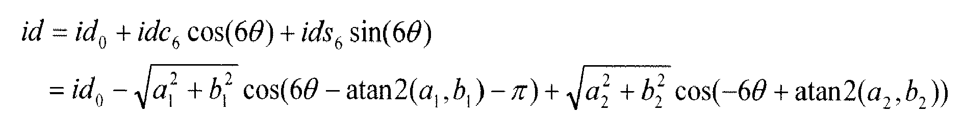


- If only the 12th and below harmonics components are to be canceled, then Id0, Iq0, Idc6, Iqc6, Ids6, and Iqs6 are calculated to obtain required torque according to the electro-magnetic torque equation by ignoring the higher harmonic components. Any appropriate harmonic current command calculation technique may be used. For one example, see Madani et al., "Reduction of torque pulsations by inductance harmonics identification of a Permanent-Magnet Synchronous Machine," Proceedings of the 4th IEEE Conference on Control Applications, September 1995, pages 787-792.
- Accordingly, if only harmonic components in flux is considered (that is, Ld, Lq are constants) and Id=0 is used in control (rotor flux oriented control), then the following equations may be used:

- Based on the assumption of
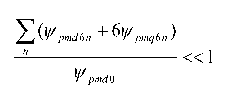
- Then, harmonic components of iqcmd are approximately linear to the torque commands and a fixed current shaping technique is feasible. Tem is the electro-magnetic torque of a permanent magnet synchronous machine. If only the non-ideality in machine magnet (flux) is considered, that is, machine flux has high order harmonics components, but machine reactance Ld, Lq does not, then the torque equation can be depicted as above. One common control strategy for a permanent synchronous machine is to cause D axis current to be zero and control the machine torque output via Q axis current. With this control strategy, Q axis current commands can be computed as the iq equation above. Furthermore, the non-ideality of machine parameters (herein the high order harmonics components in flux, e.g. ψpmd6n, ψpmq6n) is usually minor compared to main flux (herein ψpmd0). Hence the Q axis current command calculation can be simplified as the terms on the right hand side of the approximation mark above. The sine and cosine terms in current command expressions in the equation above are the harmonics current commands. Id0, Iq0 in the equation above correspond to IdCmd0 60 and
IqCmd0 62 respectively inFIG. 3 . - Based on the above analysis, one exemplary control scheme includes a feedforward channel to increase the dynamic current response, multiple closed loop channels that involve rotating frame integrators to control the steady state errors at corresponding frequencies or harmonics to zero; and, for each harmonic current, a closed loop regulator for controlling both positive sequence and negative sequence currents in order to suppress torque ripple.
-
FIG. 4 illustrates an exemplary harmonic control embodiment wherein a symmetricresonant regulator 80 is employed as the harmonic current controller.FIG. 4 shows an exemplary implementation of symmetricresonant regulators VdhReg 100 andVqhReg 116. -
FIGs. 5-7 illustrate three different types of symmetric resonant regulators.FIG. 5 shows an exemplary symmetricresonant regulator 120 that includes a proportional term Kp amplifier shown byreference numeral 124 and a resonant integrator depicted by theequation 2Kis/(s2 + (nω))2) as shown byblock 126, wherein theresonant integrator 126 controls both positive and negative component error at corresponding frequency (+n ω and -n ω) at the same time.Error 122 needs to be zero at each frequency n ω, for both positive and negative sequence and the output from theblocks harmonic voltage command 130. It may be noted that the resonant integrator is used to control the current error at specified frequency to zero and proportional term amplifier is used to increase system dynamic response. InFIG. 5 , each resonant regulator includes aproportional term 124 and aresonant integrator term 126. -
FIG. 6 shows another embodiment of a symmetricresonant regulator 132 where asine channel cosine channel error signal 134 and are used to control the harmonic component, again for both positive and negative sequence. Output signals of the sine and cosine channels are summed atsummation element 150. The proportional term Kp amplifier shown byreference numeral 144 is summed atsummation element 154 to provide regulatedharmonic voltage command 154. AlthoughFIGs. 5 and 6 each illustrate one resonant regulator for purposes of illustration, two resonant regulators are used in each embodiment (one for D axis and one for Q axis). For one example reference illustrating resonant regulator control, see Wang et al., "Design of Multiple-Reference-Frame PI Controller for Power Converters," 35th Annual IEEE Power Electronics Specialists Conference, June 2004, pages 3331-35. -
FIG. 7 shows a third embodiment of a symmetricresonant regulator 156 where the positive andnegative errors elements Regulators regulators regulators blocks VdnRegP 178,VqnRegP 180 and negative voltage commandsVdnRegN 182,VqnRegN 184 are obtained and then summed atblocks VdnReg 190 andVqnReg 192. In the DQ rotating frame, a symmetric resonant controller includes two resonant integral regulators, one for positive components +n ω (such as.blocks FIG. 7 ), and the other for negative components -n ω (such asblocks Fig. 7 ), wherein each regulator usually includes two channels (x, y channel), and wherein each channel has a proportional term and an integral term, which typically is a PI (proportional integral) regulator. - The various embodiments described herein provide electrical torque ripple control through the power converter current injection that advantageously reduces the acoustic noise of the generator in wind turbine applications. It will be well appreciated by those skilled in the art that the embodiments described herein use the general principle of shaping the current (or voltage) of the generator to reduce torque ripple (and/or acoustic noise). It should also be noted that though wind turbine generators and permanent magnet synchronous generators have been shown in exemplary embodiments, the technique is equally applicable to other generators and motors.
- While only certain features of the invention have been illustrated and described herein, many modifications and changes will occur to those skilled in the art. It is, therefore, to be understood that the appended claims are intended to cover all such modifications and changes as fall within the true spirit of the invention.
Claims (9)
- A system for controlling torque ripple in a permanent magnet synchronous machine (14) comprising:(a) a power converter (18) configured to be coupled to the permanent magnet synchronous machine and to receive converter control signals (54, 56); and(b) a system controller (20) coupled to the power converter, the system controller comprising:(i) a fundamental current controller (40) configured for providing fundamental voltage commands ( VdReg, VqReg, VdRef0, VqRef0),(ii) a harmonic current controller (42) configured for using harmonic current commands (66, 68), current feedback signals from the permanent magnet machine (58, 60), and fundamental current commands (60, 62) in combination with positive and negative sequence regulators (86, 88, 90, 102, 104, 106) to obtain harmonic voltage commands (76, 78), and(iii) summation elements (53,55) configured for adding the fundamental voltage commands and the harmonic voltage commands to obtain the converter control signals.
- The system of claim 1, wherein the harmonic current controller comprises a plurality of symmetric resonant regulators (86, 88, 90, 102, 104, 106), each symmetric resonant regulator configured for controlling positive and negative sequence harmonic currents at a specific frequency.
- The system of claim 2 wherein at least one of the symmetric resonant regulators (120) comprises a proportional term amplifier (124) and a resonant integrator (126) configured for controlling the positive and negative sequence harmonic currents.
- The system of claim 2 or claim 3 wherein the symmetric resonant regulators (86, 88, 90, 102, 104, 106) each comprise sine and cosine components configured for controlling the positive and negative sequence currents.
- A wind turbine comprising:a power converter (18) configured to be coupled to the permanent magnet synchronous machine and to receive converter control signals; anda system controller (20) coupled to the power converter, the system controller comprising:a fundamental current controller (40) configured for providing fundamental voltage commands;a harmonic current controller (42) configured for using harmonic current commands, current feedback signals from the wind turbine generator, and fundamental current commands in combination with positive and negative sequence regulators to obtain the harmonic voltage commands; andsummation elements (53, 55) configured for adding the fundamental voltage commands and the harmonic voltage commands to obtain the converter control signals.
- A wind turbine comprising:a power converter (18) configured to be coupled to a wind turbine generator and configured to receive converter control signals; anda system controller (20) coupled to the power converter, wherein the system controller is configured to supply power and/or torque control signals to the power converter to regulate the fundamental power and/or torque produced by the wind turbine generator, and wherein the system controller is further configured to supply harmonic control signals to the power converter to reduce acoustic noise and/or torque ripple generated by the wind turbine generator.
- The wind turbine of claim 6, wherein the system controller comprises:(i) a fundamental current controller (40) configured for providing fundamental voltage commands ( VdReg, VqReg, VdRef0 VqRef0),(ii) a harmonic current controller (42) configured for using harmonic current commands (66, 68), current feedback signals from the permanent magnet machine (58, 60), and fundamental current commands (60, 62) in combination with positive and negative sequence regulators (86, 88, 90, 102, 104, 106) to obtain harmonic voltage commands (76, 78), and(iii) summation elements (53,55) configured for adding the fundamental voltage commands and the harmonic voltage commands to obtain the converter control signals.
- The wind turbine of claim 7, wherein the harmonic current controller (42) comprises a plurality of symmetric resonant regulators (86, 88, 90, 102, 104, 106), each symmetric resonant regulator configured for controlling positive and negative sequence harmonic currents at a specific frequency.
- A method for controlling torque ripples in a permanent magnet synchronous generator (14), the method comprising:generating a fundamental current command;generating positive and negative sequence signals using a harmonic current command for controlling positive and negative sequence harmonic currents at a specific frequency; andobtaining a converter control signal by using the fundamental current command, the harmonic current command, a current feedback signal from the permanent magnet synchronous generator, and the positive and negative sequence signals;providing the converter control signal to a power converter (18) coupled to the permanent magnet synchronous generator.
Applications Claiming Priority (1)
| Application Number | Priority Date | Filing Date | Title |
|---|---|---|---|
| US11/863,352 US7847526B2 (en) | 2007-09-28 | 2007-09-28 | System and method for controlling torque ripples in synchronous machines |
Publications (2)
| Publication Number | Publication Date |
|---|---|
| EP2043255A2 true EP2043255A2 (en) | 2009-04-01 |
| EP2043255A3 EP2043255A3 (en) | 2018-02-07 |
Family
ID=40261228
Family Applications (1)
| Application Number | Title | Priority Date | Filing Date |
|---|---|---|---|
| EP08164664.8A Withdrawn EP2043255A3 (en) | 2007-09-28 | 2008-09-19 | System and method for controlling torque ripples in synchronous machines |
Country Status (3)
| Country | Link |
|---|---|
| US (2) | US7847526B2 (en) |
| EP (1) | EP2043255A3 (en) |
| CN (1) | CN101399515B (en) |
Cited By (24)
| Publication number | Priority date | Publication date | Assignee | Title |
|---|---|---|---|---|
| ITVA20100046A1 (en) * | 2010-06-04 | 2011-12-05 | St Microelectronics Srl | METHOD OF CONTROL OF A SYNCHRONOUS THREE-PHASE MOTOR WITH PERMANENT MAGNETS TO REDUCE NOISE AND RELATIVE CONTROL DEVICE |
| EP2405135A1 (en) * | 2010-07-09 | 2012-01-11 | Gamesa Innovation & Technology, S.L. | Methods for overcoming unwanted effects by cogging torque in a wind turbine |
| EP2485388A1 (en) * | 2011-02-04 | 2012-08-08 | Siemens Aktiengesellschaft | Reduction of noise and vibrations of an electromechanical transducer by using a modified stator coil drive signal comprising harmonic components |
| EP2552013A1 (en) * | 2011-07-27 | 2013-01-30 | Siemens Aktiengesellschaft | Reduction of noise and vibrations of an electromechanical transducer by using a modified stator coil drive signal comprising harmonic components |
| EP2552012A1 (en) * | 2011-07-27 | 2013-01-30 | Siemens Aktiengesellschaft | Reduction of noise and vibrations of an electromechanical transducer by using a modified stator coil drive signal comprising harmonic components |
| EP2768134A1 (en) * | 2013-02-19 | 2014-08-20 | Siemens Aktiengesellschaft | Voltage control for a generator of a wind turbine |
| EP2869458A1 (en) * | 2013-10-30 | 2015-05-06 | Siemens Aktiengesellschaft | Current controller of a wind turbine |
| DE102010030210B4 (en) * | 2009-06-18 | 2015-05-07 | GM Global Technology Operations LLC (n. d. Ges. d. Staates Delaware) | Methods and apparatus for diagnosing stator windings in an electric motor |
| EP3010143A1 (en) * | 2014-10-14 | 2016-04-20 | Siemens Aktiengesellschaft | Method for controlling force ripples of a generator |
| WO2016115563A1 (en) * | 2015-01-16 | 2016-07-21 | Abb Technology Ag | Systems and methods concerning exciterless synchronous machines |
| WO2016151014A1 (en) * | 2015-03-24 | 2016-09-29 | Wobben Properties Gmbh | Method for controlling a synchronous generator of a gearless wind energy turbine |
| EP3076542A1 (en) | 2015-04-02 | 2016-10-05 | Siemens Aktiengesellschaft | Noise control for a wind turbine |
| EP3264593A1 (en) * | 2016-06-30 | 2018-01-03 | Siemens Aktiengesellschaft | Control arrangement for a generator |
| EP3480931A1 (en) * | 2017-11-07 | 2019-05-08 | Siemens Gamesa Renewable Energy A/S | Harmonic control of a converter |
| EP3514944A1 (en) * | 2018-01-18 | 2019-07-24 | Siemens Gamesa Renewable Energy A/S | Method and controller controlling an electrical machine with multiple phases and windmill with the controller |
| WO2019214777A1 (en) * | 2018-05-08 | 2019-11-14 | Mdynamix Ag | Method for generating and/or compensating for vibrations by means of an electric motor |
| US10608508B2 (en) | 2017-09-28 | 2020-03-31 | Abb Schweiz Ag | Systems and methods for exciterless synchronous machines |
| EP3696969A1 (en) * | 2019-02-13 | 2020-08-19 | Siemens Gamesa Renewable Energy A/S | Harmonic control of a converter |
| US10790733B2 (en) | 2018-09-04 | 2020-09-29 | Abb Schweiz Ag | Rotor with asymmetric energy harvest windings |
| WO2020260454A1 (en) * | 2019-06-28 | 2020-12-30 | Wobben Properties Gmbh | Method for minimising generator vibrations |
| CN112368934A (en) * | 2018-06-22 | 2021-02-12 | 乌本产权有限公司 | Method for controlling a generator of a wind energy installation |
| WO2021160699A1 (en) | 2020-02-13 | 2021-08-19 | Wobben Properties Gmbh | Method for controlling an electric generator of a wind turbine |
| CN113765444A (en) * | 2021-09-29 | 2021-12-07 | 蔚来动力科技(合肥)有限公司 | Harmonic current injection method, apparatus and computer-readable storage medium for suppressing vehicle low-speed jitter |
| US11863114B2 (en) | 2019-05-06 | 2024-01-02 | Siemens Gamesa Renewable Energy A/S | Harmonic direct torque control of an electric machine |
Families Citing this family (47)
| Publication number | Priority date | Publication date | Assignee | Title |
|---|---|---|---|---|
| JP3918837B2 (en) | 2004-08-06 | 2007-05-23 | 株式会社日立製作所 | Wind power generator |
| US7642666B2 (en) * | 2006-11-02 | 2010-01-05 | Hitachi, Ltd. | Wind power generation apparatus, wind power generation system and power system control apparatus |
| KR100774308B1 (en) * | 2006-11-28 | 2007-11-08 | 한국해양연구원 | Helical Turbine Power Generation System |
| US7622817B2 (en) * | 2006-12-13 | 2009-11-24 | General Electric Company | High-speed high-pole count generators |
| US8237301B2 (en) * | 2008-01-31 | 2012-08-07 | General Electric Company | Power generation stabilization control systems and methods |
| US8125095B2 (en) * | 2008-06-18 | 2012-02-28 | Duffey Christopher K | Variable speed synchronous generator |
| WO2011037537A2 (en) * | 2009-09-24 | 2011-03-31 | Vestas Wind Systems A/S | Method for controlling a power converter in a wind turbine generator |
| US8008798B2 (en) * | 2009-12-23 | 2011-08-30 | General Electric Company | Wind turbine drivetrain system |
| CN101860294A (en) * | 2010-04-08 | 2010-10-13 | 西北工业大学 | A debounce method for sliding mode control of permanent magnet synchronous motor |
| CN103141004B (en) * | 2010-09-22 | 2016-12-07 | 东芝三菱电机产业系统株式会社 | Power inverter |
| DE102011000459B4 (en) * | 2011-02-02 | 2017-11-02 | Universität Kassel | Method for supplying reactive current with a converter and converter arrangement and energy supply system |
| US8693220B2 (en) * | 2011-10-26 | 2014-04-08 | General Electric Company | System for improved wind turbine generator performance |
| US20130119900A1 (en) * | 2011-11-10 | 2013-05-16 | Ford Global Technologies, Llc | Motor torque ripple compensation |
| US8773873B2 (en) * | 2011-12-15 | 2014-07-08 | General Electric Company | Methods and systems for operating a power converter |
| US8848400B2 (en) | 2012-02-15 | 2014-09-30 | General Electric Company | System and method for reactive power regulation |
| US8907510B2 (en) * | 2012-03-09 | 2014-12-09 | General Electric Company | Method and systems for operating a wind turbine |
| CN102946226B (en) * | 2012-05-28 | 2015-11-04 | 同济大学 | Method and device for detecting 6i-order electromagnetic torque fluctuation of permanent magnet synchronous motor |
| EP2672624B1 (en) * | 2012-06-05 | 2014-10-29 | Siemens Aktiengesellschaft | Current controller and generator system |
| JP5768770B2 (en) * | 2012-06-29 | 2015-08-26 | 株式会社デンソー | Rotating machine control device |
| US9435320B2 (en) | 2012-11-19 | 2016-09-06 | Elwha Llc | Mitigating wind turbine blade noise generation in view of a minimum power generation requirement |
| US9759196B2 (en) | 2012-11-19 | 2017-09-12 | Elwha Llc | Mitigating wind turbine blade noise generation in response to an atmospheric variation |
| US9136785B2 (en) * | 2013-03-12 | 2015-09-15 | Steering Solutions Ip Holding Corporation | Motor control system to compensate for torque ripple |
| CN104052373B (en) * | 2013-03-14 | 2017-04-12 | 通用电气公司 | motor fault protection system and method |
| TWI499193B (en) * | 2013-08-16 | 2015-09-01 | Univ Nat Cheng Kung | Power conversion apparatus and control method thereof |
| CN104767441B (en) * | 2014-01-06 | 2018-02-09 | 台达电子工业股份有限公司 | Power supply control system and method |
| US10389289B2 (en) | 2014-02-06 | 2019-08-20 | Steering Solutions Ip Holding Corporation | Generating motor control reference signal with control voltage budget |
| US10003285B2 (en) | 2014-06-23 | 2018-06-19 | Steering Solutions Ip Holding Corporation | Decoupling current control utilizing direct plant modification in electric power steering system |
| US10890905B1 (en) | 2014-08-29 | 2021-01-12 | Electro Standards Laboratories | Advanced arresting gear controller |
| US10348229B2 (en) | 2014-08-29 | 2019-07-09 | Electro Standards Laboratories | Electric motor current controller with negative sequence harmonic suppression |
| US10892694B1 (en) | 2014-08-29 | 2021-01-12 | Electro Standards Laboratories | Control system connected to an arresting gear system having an outer control loop and a plurality of inner current control loops |
| KR20160148216A (en) * | 2015-06-16 | 2016-12-26 | 현대자동차주식회사 | Device for ripple controlling alternator and method for ripple controlling using the same |
| CN106253776B (en) * | 2016-08-25 | 2018-09-11 | 国网浙江省电力公司电力科学研究院 | Generator power pick-up device and delivering method based on comprehensive harmonic failure identification |
| US10135368B2 (en) | 2016-10-01 | 2018-11-20 | Steering Solutions Ip Holding Corporation | Torque ripple cancellation algorithm involving supply voltage limit constraint |
| CN107124126B (en) * | 2017-03-31 | 2021-09-03 | 中国电力科学研究院 | Phase-loop-free current control method and device for doubly-fed induction generator |
| US10784685B2 (en) * | 2017-05-08 | 2020-09-22 | General Electric Company | Electrical power systems and subsystems |
| US20200052631A1 (en) * | 2018-08-13 | 2020-02-13 | Hamilton Sundstrand Corporation | Electric system architecture with a permanent magnet generator and interleaved active rectifiers |
| CN109672383B (en) * | 2018-12-25 | 2020-05-08 | 北京理工大学 | Salient pole type permanent magnet synchronous motor online parameter identification method |
| US10742149B1 (en) * | 2019-04-22 | 2020-08-11 | General Electric Company | System and method for reactive power control of a wind turbine by varying switching frequency of rotor side converter |
| CN112311286B (en) * | 2019-07-31 | 2023-06-30 | 北京金风科创风电设备有限公司 | Power control device and method for wind power generating set |
| CN110707972B (en) * | 2019-09-24 | 2020-12-29 | 华中科技大学 | A control method and system for a permanent magnet vernier linear motor |
| GB2590953A (en) | 2020-01-09 | 2021-07-14 | Rolls Royce Plc | Torsional mode damping controller |
| CN111800043B (en) * | 2020-06-27 | 2021-10-08 | 同济大学 | A harmonic current decoupling control system and method for a convex synchronous motor |
| CN111987956B (en) * | 2020-08-10 | 2021-10-15 | 沈阳工业大学 | A torque ripple suppression method for direct-drive wind turbines |
| ES2903009B2 (en) * | 2020-09-30 | 2022-08-04 | Univ Extremadura | VIBRATION CORRECTION PROCEDURE FOR ROTARY ELECTRIC MOTORS WITH FIELD-ORIENTED CONTROL |
| CN114337440B (en) * | 2021-12-09 | 2023-12-22 | 合肥工业大学 | Signal decoupling method and device applied to inverter under vector control |
| CN114665764B (en) * | 2022-04-21 | 2024-08-16 | 湖南工业大学 | A highly robust model-free predictive control method for permanent magnet synchronous wind turbines |
| US12119763B2 (en) * | 2022-11-02 | 2024-10-15 | GM Global Technology Operations LLC | Harmonic current command with four degrees of freedom for electric motor |
Family Cites Families (23)
| Publication number | Priority date | Publication date | Assignee | Title |
|---|---|---|---|---|
| JPH0636676B2 (en) * | 1985-03-01 | 1994-05-11 | 勲 高橋 | Control method of PWM inverter |
| US5083039B1 (en) * | 1991-02-01 | 1999-11-16 | Zond Energy Systems Inc | Variable speed wind turbine |
| JPH0723527A (en) * | 1993-06-30 | 1995-01-24 | Toshiba Corp | Reverse-phase overcurrent protection relay |
| WO1997004521A1 (en) * | 1995-07-18 | 1997-02-06 | Midwest Research Institute | A variable speed wind turbine generator system with zero-sequence filter |
| US5994881A (en) * | 1997-10-07 | 1999-11-30 | Hitachi, Ltd. | Control apparatus for a synchronous generator system and a hybrid-type electric vehicle using it |
| US5883796A (en) * | 1997-04-07 | 1999-03-16 | Wisconsin Alumni Research Foundation | Dynamic series voltage restoration for sensitive loads in unbalanced power systems |
| KR100421373B1 (en) * | 2001-06-20 | 2004-03-06 | 엘지전자 주식회사 | Apparatus for rotary velocity control of synchronous reluctance motor |
| US6777907B2 (en) * | 2001-11-06 | 2004-08-17 | International Rectifier Corporation | Current ripple reduction by harmonic current regulation |
| JP4019842B2 (en) * | 2002-07-30 | 2007-12-12 | 日産自動車株式会社 | Motor control device |
| JP4585774B2 (en) * | 2003-03-07 | 2010-11-24 | キヤノン株式会社 | Power conversion device and power supply device |
| JP4007268B2 (en) * | 2003-07-22 | 2007-11-14 | 株式会社日立製作所 | Wind power generator |
| JP3958274B2 (en) * | 2003-10-10 | 2007-08-15 | アイシン・エィ・ダブリュ株式会社 | Discharge control device, discharge control method and program thereof |
| US7208908B2 (en) * | 2004-07-12 | 2007-04-24 | Honeywell International Inc. | Apparatus and method to control torque and voltage of an AC machine |
| US7355865B2 (en) * | 2004-08-13 | 2008-04-08 | Rockwell Automation Technologies, Inc. | Method and apparatus for rejecting the second harmonic current in an active converter with an unbalanced AC line voltage source |
| US7679215B2 (en) * | 2004-12-17 | 2010-03-16 | General Electric Company | Wind farm power ramp rate control system and method |
| US7680562B2 (en) * | 2005-09-08 | 2010-03-16 | General Electric Company | Power generation system |
| US7504738B2 (en) * | 2005-09-29 | 2009-03-17 | General Electric Company | Wind turbine and method for operating same |
| US7345373B2 (en) * | 2005-11-29 | 2008-03-18 | General Electric Company | System and method for utility and wind turbine control |
| US7446435B2 (en) * | 2005-11-30 | 2008-11-04 | General Electric Company | Power converter system and method |
| US7423412B2 (en) * | 2006-01-31 | 2008-09-09 | General Electric Company | Method, apparatus and computer program product for injecting current |
| JP2008011607A (en) * | 2006-06-28 | 2008-01-17 | Hitachi Ltd | Variable speed wind power generation system |
| US7952232B2 (en) * | 2008-03-13 | 2011-05-31 | General Electric Company | Wind turbine energy storage and frequency control |
| JP5281329B2 (en) * | 2008-07-25 | 2013-09-04 | 本田技研工業株式会社 | Inverter generator |
-
2007
- 2007-09-28 US US11/863,352 patent/US7847526B2/en not_active Expired - Fee Related
-
2008
- 2008-09-19 EP EP08164664.8A patent/EP2043255A3/en not_active Withdrawn
- 2008-09-26 CN CN2008101687345A patent/CN101399515B/en not_active Expired - Fee Related
-
2010
- 2010-10-07 US US12/899,918 patent/US7982326B2/en not_active Expired - Fee Related
Non-Patent Citations (2)
| Title |
|---|
| MADANI ET AL.: "Reduction of torque pulsations by inductance harmonics identification of a Permanent-Magnet Synchronous Machine", PROCEEDINGS OF THE 4TH IEEE CONFERENCE ON CONTROL APPLICATIONS, September 1995 (1995-09-01), pages 787 - 792, XP000751222 |
| WANG ET AL.: "Design of Multiple-Reference-Frame PI Controller for Power Converters", 35TH ANNUAL IEEE POWER ELECTRONICS SPECIALISTS CONFERENCE, June 2004 (2004-06-01), pages 3331 - 35, XP002737554, DOI: doi:10.1109/PESC.2004.1355064 |
Cited By (46)
| Publication number | Priority date | Publication date | Assignee | Title |
|---|---|---|---|---|
| DE102010030210B4 (en) * | 2009-06-18 | 2015-05-07 | GM Global Technology Operations LLC (n. d. Ges. d. Staates Delaware) | Methods and apparatus for diagnosing stator windings in an electric motor |
| US8816616B2 (en) | 2010-06-04 | 2014-08-26 | Stmicroelectronics S.R.L. | Method of controlling a three-phase permanent magnet synchronous motor for reducing acoustic noise |
| ITVA20100046A1 (en) * | 2010-06-04 | 2011-12-05 | St Microelectronics Srl | METHOD OF CONTROL OF A SYNCHRONOUS THREE-PHASE MOTOR WITH PERMANENT MAGNETS TO REDUCE NOISE AND RELATIVE CONTROL DEVICE |
| EP2405135A1 (en) * | 2010-07-09 | 2012-01-11 | Gamesa Innovation & Technology, S.L. | Methods for overcoming unwanted effects by cogging torque in a wind turbine |
| ES2400088R1 (en) * | 2010-07-09 | 2013-04-12 | Gamesa Innovation & Tech Sl | METHODS TO AVOID INDESATED EFFECTS OF THE IRREGULAR ROTATION TORQUE IN AN AIRBRUSHER |
| EP2485388A1 (en) * | 2011-02-04 | 2012-08-08 | Siemens Aktiengesellschaft | Reduction of noise and vibrations of an electromechanical transducer by using a modified stator coil drive signal comprising harmonic components |
| EP2552013A1 (en) * | 2011-07-27 | 2013-01-30 | Siemens Aktiengesellschaft | Reduction of noise and vibrations of an electromechanical transducer by using a modified stator coil drive signal comprising harmonic components |
| EP2552012A1 (en) * | 2011-07-27 | 2013-01-30 | Siemens Aktiengesellschaft | Reduction of noise and vibrations of an electromechanical transducer by using a modified stator coil drive signal comprising harmonic components |
| US9263980B2 (en) | 2011-07-27 | 2016-02-16 | Siemens Aktiengesellschaft | Reduction of noise and vibrations of an electromechanical transducer by using a modified stator coil drive signal comprising harmonic components |
| EP2768134A1 (en) * | 2013-02-19 | 2014-08-20 | Siemens Aktiengesellschaft | Voltage control for a generator of a wind turbine |
| EP2869458A1 (en) * | 2013-10-30 | 2015-05-06 | Siemens Aktiengesellschaft | Current controller of a wind turbine |
| EP3010143A1 (en) * | 2014-10-14 | 2016-04-20 | Siemens Aktiengesellschaft | Method for controlling force ripples of a generator |
| WO2016115563A1 (en) * | 2015-01-16 | 2016-07-21 | Abb Technology Ag | Systems and methods concerning exciterless synchronous machines |
| US9813004B2 (en) | 2015-01-16 | 2017-11-07 | Abb Schweiz Ag | Systems and methods concerning exciterless synchronous machines |
| US10097123B2 (en) | 2015-01-16 | 2018-10-09 | Abb Schweiz Ag | Systems and methods concerning exciterless synchronous machines |
| TWI641211B (en) * | 2015-03-24 | 2018-11-11 | 德商渥班資產公司 | Method for controlling a synchronous generator of a gearless wind turbine |
| JP2018509878A (en) * | 2015-03-24 | 2018-04-05 | ヴォッベン プロパティーズ ゲーエムベーハーWobben Properties Gmbh | Control method of synchronous generator of gearless wind power generator |
| WO2016151014A1 (en) * | 2015-03-24 | 2016-09-29 | Wobben Properties Gmbh | Method for controlling a synchronous generator of a gearless wind energy turbine |
| KR20170128520A (en) * | 2015-03-24 | 2017-11-22 | 보벤 프로퍼티즈 게엠베하 | How to Control the Synchronous Generator of a Gearless Wind Turbine |
| EP3076542A1 (en) | 2015-04-02 | 2016-10-05 | Siemens Aktiengesellschaft | Noise control for a wind turbine |
| US10100811B2 (en) | 2015-04-02 | 2018-10-16 | Siemens Aktiengesellschaft | Noise control for a wind turbine |
| EP3076542B1 (en) | 2015-04-02 | 2019-05-29 | Siemens Gamesa Renewable Energy A/S | Noise control for a wind turbine |
| EP3264593A1 (en) * | 2016-06-30 | 2018-01-03 | Siemens Aktiengesellschaft | Control arrangement for a generator |
| CN107565871A (en) * | 2016-06-30 | 2018-01-09 | 西门子公司 | Control arrangements for generators |
| CN107565871B (en) * | 2016-06-30 | 2020-09-01 | 西门子歌美飒可再生能源公司 | Control arrangements for generators |
| US10608508B2 (en) | 2017-09-28 | 2020-03-31 | Abb Schweiz Ag | Systems and methods for exciterless synchronous machines |
| EP3480931A1 (en) * | 2017-11-07 | 2019-05-08 | Siemens Gamesa Renewable Energy A/S | Harmonic control of a converter |
| US10374538B2 (en) | 2017-11-07 | 2019-08-06 | Siemens Gamesa Renewable Energy A/S | Harmonic control of a converter |
| WO2019141600A1 (en) | 2018-01-18 | 2019-07-25 | Siemens Gamesa Renewable Energy A/S | Method of controlling a multi-channel multi-phase electrical machine |
| US11223308B2 (en) | 2018-01-18 | 2022-01-11 | Siemens Gamesa Renewable Energy A/S | Method of controlling a multi-channel multi-phase electrical machine |
| CN111566925A (en) * | 2018-01-18 | 2020-08-21 | 西门子歌美飒可再生能源公司 | Method for controlling a multi-channel polyphase machine |
| EP3514944A1 (en) * | 2018-01-18 | 2019-07-24 | Siemens Gamesa Renewable Energy A/S | Method and controller controlling an electrical machine with multiple phases and windmill with the controller |
| CN111566925B (en) * | 2018-01-18 | 2024-01-12 | 西门子歌美飒可再生能源公司 | Methods for controlling multi-channel multi-phase motors |
| WO2019214777A1 (en) * | 2018-05-08 | 2019-11-14 | Mdynamix Ag | Method for generating and/or compensating for vibrations by means of an electric motor |
| US11949352B2 (en) | 2018-06-22 | 2024-04-02 | Wobben Properties Gmbh | Method for controlling a generator of a wind turbine |
| CN112368934A (en) * | 2018-06-22 | 2021-02-12 | 乌本产权有限公司 | Method for controlling a generator of a wind energy installation |
| US10790733B2 (en) | 2018-09-04 | 2020-09-29 | Abb Schweiz Ag | Rotor with asymmetric energy harvest windings |
| EP3696969A1 (en) * | 2019-02-13 | 2020-08-19 | Siemens Gamesa Renewable Energy A/S | Harmonic control of a converter |
| US11365717B2 (en) | 2019-02-13 | 2022-06-21 | Siemens Gamesa Renewable Energy A/S | Harmonic control of a converter |
| CN111564997B (en) * | 2019-02-13 | 2023-11-21 | 西门子歌美飒可再生能源公司 | Harmonic control of a converter |
| CN111564997A (en) * | 2019-02-13 | 2020-08-21 | 西门子歌美飒可再生能源公司 | Harmonic control of a converter |
| US11863114B2 (en) | 2019-05-06 | 2024-01-02 | Siemens Gamesa Renewable Energy A/S | Harmonic direct torque control of an electric machine |
| WO2020260454A1 (en) * | 2019-06-28 | 2020-12-30 | Wobben Properties Gmbh | Method for minimising generator vibrations |
| WO2021160699A1 (en) | 2020-02-13 | 2021-08-19 | Wobben Properties Gmbh | Method for controlling an electric generator of a wind turbine |
| CN113765444A (en) * | 2021-09-29 | 2021-12-07 | 蔚来动力科技(合肥)有限公司 | Harmonic current injection method, apparatus and computer-readable storage medium for suppressing vehicle low-speed jitter |
| CN113765444B (en) * | 2021-09-29 | 2023-06-02 | 蔚来动力科技(合肥)有限公司 | Harmonic current injection method, apparatus and computer readable storage medium for suppressing vehicle low-speed jitter |
Also Published As
| Publication number | Publication date |
|---|---|
| EP2043255A3 (en) | 2018-02-07 |
| US20090085354A1 (en) | 2009-04-02 |
| US20110018281A1 (en) | 2011-01-27 |
| US7847526B2 (en) | 2010-12-07 |
| CN101399515B (en) | 2013-09-11 |
| CN101399515A (en) | 2009-04-01 |
| US7982326B2 (en) | 2011-07-19 |
Similar Documents
| Publication | Publication Date | Title |
|---|---|---|
| US7847526B2 (en) | System and method for controlling torque ripples in synchronous machines | |
| Hu et al. | Direct active and reactive power regulation of DFIG using sliding-mode control approach | |
| Cárdenas et al. | Control strategies for power smoothing using a flywheel driven by a sensorless vector-controlled induction machine operating in a wide speed range | |
| Mohammadi et al. | A combined vector and direct power control for DFIG-based wind turbines | |
| Cardenas et al. | Control of a switched reluctance generator for variable-speed wind energy applications | |
| EP3264593B1 (en) | Control arrangement for a generator | |
| US7619327B2 (en) | Hybrid electromechanical power transfer system | |
| US10848087B2 (en) | Control arrangment for a generator | |
| US10374538B2 (en) | Harmonic control of a converter | |
| Haque et al. | Advanced control scheme for an IPM synchronous generator-based gearless variable speed wind turbine | |
| Zhao et al. | The dynamic control of reactive power for the brushless doubly fed induction machine with indirect stator-quantities control scheme | |
| Ali et al. | Wind-speed estimation and sensorless control for SPMSG-based WECS using LMI-based SMC | |
| Karthikeyan et al. | A versatile rotor position computation algorithm for the power control of a grid-connected doubly fed induction generator | |
| Zhu et al. | Second-order sliding-mode control of DFIG-based wind turbines | |
| Huang et al. | Dynamic performance improvement for permanent magnet generator system using current compensating method with two-degrees-of-freedom control | |
| CN103746623A (en) | Maximum available torque weak magnetic control method for permanent-magnet direct-drive wind turbine | |
| Kumar et al. | Maximum power point tracking for a PMSG based variable speed wind energy conversion system using optimal torque control | |
| Said et al. | Torque ripple minimization in dual inverter open-end winding PMSM drives with non-sinusoidal back-EMFs by harmonic current suppression | |
| Wu et al. | A novel power-angle control method of DFIG-DC system based on regulating air gap flux vector | |
| CN109600088B (en) | A harmonic current injection device and method for a three-phase inverter | |
| Khatab et al. | A Comparative Study of Field Oriented and Backstepping Control Strategies for Wind turbine PM Synchronous Generator | |
| Gaol et al. | Model reference adaptive system observer based sensorless control of doubly-fed induction machine | |
| US11365717B2 (en) | Harmonic control of a converter | |
| Solomon | The design, control and dynamic performance of an interior permanent magnet synchronous generator for wind power system | |
| Pravica et al. | Torque control of a wind power permanent magnet generator in a flux weakening region |
Legal Events
| Date | Code | Title | Description |
|---|---|---|---|
| PUAI | Public reference made under article 153(3) epc to a published international application that has entered the european phase |
Free format text: ORIGINAL CODE: 0009012 |
|
| AK | Designated contracting states |
Kind code of ref document: A2 Designated state(s): AT BE BG CH CY CZ DE DK EE ES FI FR GB GR HR HU IE IS IT LI LT LU LV MC MT NL NO PL PT RO SE SI SK TR |
|
| AX | Request for extension of the european patent |
Extension state: AL BA MK RS |
|
| PUAL | Search report despatched |
Free format text: ORIGINAL CODE: 0009013 |
|
| AK | Designated contracting states |
Kind code of ref document: A3 Designated state(s): AT BE BG CH CY CZ DE DK EE ES FI FR GB GR HR HU IE IS IT LI LT LU LV MC MT NL NO PL PT RO SE SI SK TR |
|
| AX | Request for extension of the european patent |
Extension state: AL BA MK RS |
|
| RIC1 | Information provided on ipc code assigned before grant |
Ipc: H02P 21/00 20160101AFI20180103BHEP Ipc: H02P 29/00 20160101ALI20180103BHEP Ipc: H02P 6/18 20160101ALI20180103BHEP Ipc: H02P 9/42 20060101ALI20180103BHEP |
|
| AKY | No designation fees paid | ||
| AXX | Extension fees paid |
Extension state: BA Extension state: AL Extension state: RS Extension state: MK |
|
| REG | Reference to a national code |
Ref country code: DE Ref legal event code: R108 |
|
| STAA | Information on the status of an ep patent application or granted ep patent |
Free format text: STATUS: THE APPLICATION IS DEEMED TO BE WITHDRAWN |
|
| 18D | Application deemed to be withdrawn |
Effective date: 20180808 |