EP2042875A2 - Sample processing apparatus and data processing apparatus - Google Patents
Sample processing apparatus and data processing apparatus Download PDFInfo
- Publication number
- EP2042875A2 EP2042875A2 EP08016698A EP08016698A EP2042875A2 EP 2042875 A2 EP2042875 A2 EP 2042875A2 EP 08016698 A EP08016698 A EP 08016698A EP 08016698 A EP08016698 A EP 08016698A EP 2042875 A2 EP2042875 A2 EP 2042875A2
- Authority
- EP
- European Patent Office
- Prior art keywords
- sample
- data
- processing apparatus
- sample processing
- program
- Prior art date
- Legal status (The legal status is an assumption and is not a legal conclusion. Google has not performed a legal analysis and makes no representation as to the accuracy of the status listed.)
- Granted
Links
Images



Classifications
-
- G—PHYSICS
- G01—MEASURING; TESTING
- G01N—INVESTIGATING OR ANALYSING MATERIALS BY DETERMINING THEIR CHEMICAL OR PHYSICAL PROPERTIES
- G01N35/00—Automatic analysis not limited to methods or materials provided for in any single one of groups G01N1/00 - G01N33/00; Handling materials therefor
- G01N35/00584—Control arrangements for automatic analysers
- G01N35/00722—Communications; Identification
- G01N35/00871—Communications between instruments or with remote terminals
-
- G—PHYSICS
- G01—MEASURING; TESTING
- G01N—INVESTIGATING OR ANALYSING MATERIALS BY DETERMINING THEIR CHEMICAL OR PHYSICAL PROPERTIES
- G01N33/00—Investigating or analysing materials by specific methods not covered by groups G01N1/00 - G01N31/00
- G01N33/48—Biological material, e.g. blood, urine; Haemocytometers
Definitions
- the present invention relates to a sample processing apparatus and data processing apparatus, for example a sample processing apparatus and data processing apparatus for measuring a sample.
- the liquid chromatographic analyzer disclosed in Japanese Laid-Open Patent No. 10-197509 is provided with an analyzing part for analyzing a target sample, and a data processing part for obtaining analysis results by performing an analysis process on the data obtained by the analyzing part.
- the analyzing part is provided with a controller for controlling the operation of the analyzing part.
- the data processing part is a personal computer which is configured so as to perform analysis processing of data obtained by the analyzing part.
- a first aspect of the present invention is a sample processing apparatus, comprising: a sample processing unit for processing a sample, wherein the sample processing unit comprises an operating device for processing a sample, a drive circuit for driving the operating device, and a first communication part which is configured so as to be capable of external communication; and a data processing unit for processing data output from the sample processing unit, wherein the data processing unit comprises a processor for generating control data for controlling the operating device, and a second communication part which is configured so as to be capable of communicating with the first communication part for transmitting the control data generated by the processor to the first communication part, wherein the drive circuit is configured so as to drive the operating device based on the control data received by the first communication part.
- a second aspect of the present invention is a data processing apparatus, comprising: a memory for storing a control program for controlling an operating device of a sample processing apparatus for processing a sample; a processor for executing a control program stored in the memory, and generating control data for controlling the operating device; and a communication part which is connected so as to be capable of communication with the sample processing apparatus, for transmitting the control data generated by the processor to the sample processing apparatus.
- a third aspect of the present invention is a sample processing apparatus, comprising: a sample processing unit for processing a sample; and a data processing unit for processing data output from the sample processing unit, wherein the sample processing unit includes a memory under control of a processor, the memory storing a first program for generating control data controlling the sample processing unit, a second program for processing the data output from the sample processing unit, and an operating system which determines priority of program execution, wherein the first program and the second program are stored in the memory such that the first program is executed by interrupting execution of the second program under control of the operating system.
- FIG. 1 is a perspective view showing the general structure of an embodiment of the blood analyzer of the present invention.
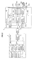
- FIG. 2 is a block diagram showing the structure of the measuring unit and data processing unit of the embodiment of the present invention.
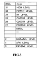
- FIG. 3 illustrates the structure of the OS used in the blood analyzer of the embodiment shown in FIG. 1 .
- the general structure of an embodiment of the blood analyzer 1 of the present invention is described below with reference to Figs. 1 through 3 .
- the blood analyzer 1 of the embodiment of the present invention is an apparatus which analyzes the blood cells in blood by irradiating each particle with laser light as the particles such as cells and hemocytes are directed through a flow cell, and then detecting the scattered light and fluorescent light from each particle.
- the blood analyzer 1 is configured by a measuring unit 2 which has the function of measuring the sample blood, and a data processing unit 3 for processing the measurement results output from the measuring unit to obtain analysis results.
- the measuring unit 2 is provided with a blood cell detector 4, a drive circuit 5 for driving (operating) the detector 4, a waveform processing circuit 6 for performing waveform processing of the signals output from the detector 4, a dispensing actuator 7 which is actuated when dispensing a sample, a drive circuit 8 for driving the dispensing actuator 7, a measuring actuator 9 which outputs measurement data, and a drive circuit 10 for driving the measuring actuator 9.
- the detector 4 is configured as an optical detector. Specifically, the detector 4 is configured so as to detect cells and particles such as blood cells and the like in blood by flow cytometry. Note that flow cytometry is a method for measuring physical properties and chemical properties of cells and other biological particles by passing the cells and other biological particles through a narrow passage. The detector 4 is configured so as to detect the forward scattered light, side scattered light, and side fluorescent light emitted from the blood cells which are irradiated by laser light.
- the drive circuit 5 is connected to the detector 4 and the drive circuit 5 is also connected to a register 11.
- the detector 4 is configured so that the drive circuit 5 operates and drives the laser light oscillation and the like by outputting signals according to the control data which is to be described layer that is stored in the register 11.
- the detector 4 is also configured to be capable of converting the respectively detected forward scattered light, side scattered light, and side fluorescent light from optical signals to electrical signals.
- the waveform processing circuit 6 is connected to the detector 4, and the various electrical signals which have been converted from optical signals are transmitted to the waveform processing circuit 6.
- the waveform processing circuit 6 is configured so as to be capable of then amplifying the electrical signals of the forward scattered light, side scattered light, and side fluorescent light, and performing waveform processing of the amplified electrical signals of the side scattered light.
- the waveform processing circuit 6 is also connected to the register 11, and is configured so as to store the electrical signals processed by the waveform processing circuit 6 in the register 11.
- the drive circuit 8 is connected to the dispensing actuator 7, and the drive circuit 10 is connected to the measuring actuator 9.
- the drive circuits 8 and 10 are respectively connected to the register 11, and the dispensing actuator 7 and the measuring actuator 9 are configured so as to be driven according to the control signals output by the drive circuit 8 and drive circuit 10 according to the control data stored in the register 11 which will be described later.
- a communication interface 12 is also connected to the register 11.
- the communication interface 12 is a USB serial interface, and is configured so as to be connectable by a USB cable to a communication interface 301f of the data processing unit 3 which will be described later. Data is thus transmitted and received to/from the data processing unit 3.
- the data processing unit 3 is configured by a personal computer (PC), and includes a controller 301 configured by a CPU, RAM, ROM and the like, a display part 302, and an input device 303.
- the display part 302 is provided to display the analysis results obtained by processing the data of the digital signals received from the measuring unit 2.
- the data processing unit 3 is a computer which is mainly configured by a controller 301, display part 302, and input device 303.
- the controller 301 is mainly configured by a CPU 301a (for example, a Celeron 2,000 MHz), ROM 301b, RAM 301c, (for example, 512 MB RAM), hard disk 301d, reading device 301e, communication interface 301f, and image output interface 301g.
- the a CPU 301a, ROM 301b, RAM 301c, hard disk 301d, reading device 301e, communication interface 301f, and image output interface 301g are connected by a bus 301h.
- the CPU 301a is capable of executing computer programs stored in the ROM 301b, and computer programs loaded in the RAM 301c.
- the computer functions as the data processing unit 3 when the CPU 301a executes an application program 304a and control program 304b which will be described later.
- the CPU 301a is configured so as to execute at predetermined time intervals (on average approximately every 100 msec) a process for generating control data (control signals) for controlling the dispensing actuator 7, and measuring actuator 9, and detector 4 of the measuring unit 2.
- the ROM 110b is configured by a mask ROM, PROM, EPROM, EEPROM or the like, and stores computer programs executed by the CPU 301a and data and the like used in conjunction therewith.
- the RAM 301c is configured by SRAM, DRAM or the like.
- the RAM 301c is used when reading the computer programs recorded in the ROM 301b and stored on the hard drive 301d.
- the RAM 301c is also used as a work area of the CPU 301a when the computer programs are being executed.
- the hard drive 301d contains various installed computer programs to be executed by the CPU 301a such as an operating system and application programs and the like, as well as data used in the execution of these computer programs.
- the application program which is to be described later is stored on the hard disk 401d together with the control program 304b and operating system 304c.
- the reading device 301e is configured by a floppy disk drive, CD-ROM drive, DVD-ROM drive or the like, and is capable of reading the computer programs and data stored on a portable recording medium 304.
- the portable recording medium 304 stores the application program 304a and control program 304b for realizing the functions the data processing unit in a computer, and the application 304a and the control program 304b are read from the portable recording medium 304 by the computer, which installs the application program 304a and the control program 304b on the hard disk 301d.
- the application program 304a and control program 304b are not only provided through the portable recording medium 304 inasmuch as the application program 304a and control program 304b may also be provided from an external device which is connected to the computer over an electric communication line so as to be capable of communication by this electric communication line (whether wire line or wireless).
- the computer may access the server computer and download the application program 304a and control program 304b, which are then installed on the hard disk 301d.
- An operating system (OS) 304c which provides a graphical user interface environment, for example, Windows (registered trademark) or the like, a product of Microsoft Corporation, USA, is installed on the hard disk 301d.
- OS operating system
- the operating system 304c determines the priority for executing the programs between the application program 304a and the control program 304b, and executes these programs according to the determined priority.
- the communication interface 301f is a USB serial interface similar to the previously mentioned communication interface 12.
- the input device 303 (refer to FIG. 1 ) which is configured by a mouse and keyboard is connected to the communication interface 301f, and a user can input data to the data processing unit 3 by using the input device 303.
- the communication interface 301f of the data processing unit 3 and the communication interface 12 of the measuring unit 2 are respectively configured so as to transmit and receive control data (control signals) which are generated based on the control program 304b by interrupt transfer, which is a transfer method that guarantees the data transfer time.
- the measuring unit 2 and the data processing unit 3 of the present embodiment are thus configured so that the control data (control signals) generated by the CPU 301 of the data processing unit 3 are received by the measuring unit 2 within a fixed time.
- interrupt transfer is transfer method for reliably transferring a predetermined amount of data (for example, 1,000 bytes) at predetermined time intervals (for example, 125 msec).
- the image output interface 301g is connected to the display part 302 which is configured by an LCD, CRT or the like, and outputs image signals according to the image data received from the CPU 301a to the display part 302.
- the display part 302 is configured so as to display an image (screen) based on the input image signals.
- the application program 304a which is installed on the hard disk 301d of the controller 301 of the data processing unit 3 is configured so as to measure the amount of blood cells of a measurement sample using the forward scattered light, side scattered light, and side fluorescent light (digital signal data) received from the communication interface 12 of the measuring unit 2, and process the measurement data.
- the control program 304b which is installed on the hard disk 301d generates control data (control signals) for controlling the drive circuits 5, 8, and 10, and the waveform processing circuit 6, and the generated control data are transmitted to the measuring unit 2 through a USB gate 20 which is connected to the communication interface 301f.
- the transmitted control data is written to (stored in) the register 11 which is connected to the communication interface 12.
- control the measuring unit 2 It is thus possible to control the measuring unit 2, and further possible to drive and operate the dispensing actuator 7 and the measuring actuator 9, and detector 4 of the measuring unit 2 based on the control data generated by the CPU 301a of the data processing unit without providing a microprocessor such as a CPU or the like in the measuring unit 2.
- the control program 304b is configured so as to control the operation of other devices in addition to the measuring unit 2 as well as the dispensing actuator 7, measuring actuator 9, and detector 4 of the measuring unit 2.
- the control data includes, for example, data such as the amount of drive and drive timing and the like of the stepping motor included in the dispensing actuator 7 when controlling the dispensing actuator.
- the application program 304a which is a program for processing measurement data is configured so as to be executable at the user level of the operating system 304c, that is, Windows (registered trademark), and the control program 304b which is a program for controlling the drive circuits 5, 8, and 10 is configured so as to be executable at the kernel level of the highest priority process rather than at the user level of Windows (registered trademark). That is, the application program 304a is stored on the hard disk 301d so as to be executable at the user level of Windows, and the control program 304b is stored on the hard disk 301d so as to be executable at the kernel level of Windows.
- interrupt request levels are provided in Windows (registered trademark), and the IRQL have a hierarchy of 0 to 31, as shown in FIG. 3 .
- the process performed at the hierarchical level with the highest IRQL number is executed preferentially over processes at hierarchical levels with lower numbers. Even when a process is being performed at a low hierarchical level (low level) and a process is to be performed at a hierarchical level with a high IRQL number (high level), the process being performed at the low level is interrupted and the high level process is performed.
- the application program 304a which is a program for processing the measurement data of the blood analyzer 1 of the present embodiment is configured so as to execute at the PASSIVE_LEVEL (user level) in FIG. 3
- the control program 304b which is a program for controlling the drive circuits 5 8, and 10 of the measuring unit 2 is configured so as to execute at the DISPATCH_LEVEL (kernel level) in FIG. 3
- the processes which are performed at levels higher than the DISPATCH_LEVEL in FIG. 3 are referred to as hardware interrupts, and a hardware interrupt may be executed a plurality of times during the operation process performed by the CPU 301a.
- the CPU 301a is configured so as to execute at predetermined time intervals (on average approximately every 100 msec) a process for generating control data (control signals) for controlling the dispensing actuator 7, measuring actuator 9, and detector 4 of the measuring unit 2.
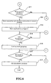
- FIG. 4 is a timing chart illustrating the CPU operation time of the blood analyzer of the embodiment shown in FIG. 1 .
- the timing chart shows the time on the horizontal axis, and on the vertical axis shows the height of the priority rank of the IRQL shown in FIG. 3 . Examples of the processing method are described below in the cases when the CPU 301a executes the application program 304a and the control program 304b.
- the CPU 301a executes the application program 304a at the PASSIVE_LEVEL, and at time t0 starts the process of generating control data by the control program at the DISPATCH_LEVEL, as shown in FIG. 4 .
- the CPU 301a interrupts the process of the PASSIVE_LEVEL application program 304a during the processing of the control program 304b because the DISPATCH_LEVEL control program 304b is processed preferentially.
- a hardware interrupt is raised by DIRQL at time t1.
- the CPU 301a interrupts the process of the DISPATCH_LEVEL control program 304b while processing the hardware interrupt because the DIRQL hardware interrupt is processed preferentially.
- the DIRQL hardware interrupt ends.
- the process of the DISPATCH_LEVEL control program 304b is restarted in conjunction with the end of the hardware interrupt.
- the CPU 301a does not restart the process of the PASSIVE_LEVEL application program 304a during the processing of the control program 304b because the DISPATCH_LEVEL control program 304b is processed preferentially.
- time interval (t3-t0) between the time t0 when the process of the control program 304b is started to generate control data and the time t3 when the process for generating control data ends is approximately 0.5 msec when using a 2,000 MHz Celeron processor with 512 MB of RAM, and approximately 0.5% of the time interval (t4-t0: approximately 100 msec) until the process of the control program 304b for generating control data is restarted.
- the time interval (t2-t1) between the time t1 when the hardware interrupt starts to the time t2 when the hardware interrupt ends is generally approximately 0.1 msec, so brief as to be normally negligible.
- FIGS. 5 and 6 are flow charts illustrating the measurement flow and processing flow of the measuring unit and the data processing unit of the blood analyzer of the embodiment shown in FIG. 1 .
- the operation when CPU 301a performs the processes of the application program 304a and the control program 304b of the embodiment of the blood analyzer of the present invention is described below with reference to FIGS. 1 , 2 , 5 , and 6 .
- step S1 of FIG. 5 When a main switch (not shown in the drawing) of the data processing unit 3 is turned on in step S1 of FIG. 5 , the CPU 301a (refer to FIG. 2 is initialized and subsequently the Windows (registered trademark) OS of the data processing unit 3 is started.
- step S2 the CPU 301a (refer to FIG. 2 ) determines whether or not the USB cable 20 is connected to both the communication interface 301f of the data processing unit 3 and the communication interface 12 of the measuring unit 2.
- step S2 determines whether or not the USB cable 20 is connected to both the communication interface 301f of the data processing unit 3 and the communication interface 12 of the measuring unit 2.
- step S16 the process then moves to step S16 which will be described later.
- the process then moves to steep S3.
- step S3 the CPU 301a starts the control program 304b at the DISPATCH_LEVEL of the kernel level, and the process moves to step S4.
- step S4 a check is made as to whether or not a start instruction of the application program 304a has been received by selection from the start menu or double clicking on a predetermined icon.
- step S5 the CPU 301a starts the application program 304a at the PASSIVE_LEVEL of the user level, and the process moves to step S6.
- the CPU 301a has determined that the application program 304a start instruction has not been received in step S4
- the process moves to step S14 of FIG. 6 which will be described later.
- step S6 a check is made to determine whether or not a measurement start instruction has been transmitted to the measuring unit 2 through the USB cable 20 by pressing a start switch which is not shown in the drawing provided on the measuring unit 2.
- a measurement start instruction has not been transmitted to the data processing unit 3 in step S6
- the process moves to step S11 in FIG. 6 which will be described later.
- the process moves to step S7 and a measurement start request for starting the measurement in the measuring unit 2 is issued to the control program 304b by inter-program communication between the application program 304a and the control program 304b.
- the CPU 301a generates control data at approximate 100 msec intervals as previously described based on the control program 304b, the generated control data are written to the register 11 of the measuring unit 2 through the USB cable 20, and the drive circuits 5, 8, and 10 are driven.
- step S8 determines whether or not measurement data processed by the waveform processing circuit 6 after detection by the detector 4 of the measuring unit 2 have been received in step S8. When it has been determined that measurement data have not been received in step S8. the process of step S8 is repeated. When it has been determined that measurement data have been received in step S8, the process moves to step S9.
- step S10 the analysis results are displayed on the display part 302, and the process moves to step S11 of FIG. 6 .
- the CPU 301a determines whether or not a shutdown instruction has been received from the user to shut down the blood analyzer 1 in step S11, as shown in FIG. 6 .
- the user can issue a shutdown instruction to shut down the blood analyzer 1 by clicking a shutdown icon which is not shown in the drawing displayed on the display part 302 of the data processing unit 3, or selecting shutdown from a menu in a display screen of the application program 304a.
- the CPU 301a does not determine that a shutdown instruction has been received in step S11, the process returns to the process of step S6 of FIG. 5 , and the operations from step S6 to step S11 are thereby repeated.
- step S11 When it has been determined that a blood analyzer 1 shutdown instruction has been received in step S11, the process moves to step S12 and a shutdown request to shut down the measuring unit 2 is issued to the control program 304b by inter-program communication between the application program 304a and the control program 304b. Then, a shutdown operation which includes washing operations and the like is executed for each part of the measuring unit 2, and the power to the measuring unit 2 is subsequently turned off.
- step S13 the CPU 301a ends the application program 304a, and the process moves to step S14.
- step S14 a determination is made as to whether or not the connection between the communication interface 301f of the data processing unit 3 and the communication interface 12 of the measuring unit 2 has been disconnected by the USB cable 20.
- step S14 determines that the connection between the communication interface 301f of the data processing unit 3 and the communication interface 12 of the measuring unit 2 has not been disconnected.
- step S14 when it has been determined in step S14 that the connection between the communication interface 301f of the data processing unit 3 and the communication interface 12 of the measuring unit 2 has been disconnected, the process moves to step S15 and the CPU 301a ends the control program 304b, and the process moves to step S16.
- step S16 the CPU 301a determines whether or not an OS shutdown instruction has been issued by selecting shutdown from the start menu of Windows (registered trademark) of the data processing unit 3.
- step S16 the process returns to step S2 of FIG. 5 .
- step S17 the process moves to step S17 and the CPU 301a performs the shutdown process of Windows (registered trademark) of the data processing unit 3, and the process ends.
- the dispensing actuator 7, measuring actuator 9 and detector 4 of the measuring device 2 can be driven without providing a CPU in the measuring device 2 by providing the data processing unit 3 with a CPU 301a for executing at predetermined time intervals (approximately 100 msec) a process for generating control data for controlling the detector 4, dispensing actuator 7, and measuring actuator 9, transmitting the control data generated by the CPU 301a to the measuring unit 2, and configuring the drive circuits 5, 8, and 10 of the measuring unit 2 so as to drive the dispensing actuator 7 and measuring actuator 9, and detector 4 of the measuring unit 2 based on the control data transmitted from the measuring unit 2.
- the structure of the apparatus is therefore less complex and the manufacturing cost of the apparatus is reduced.
- the dispensing actuator 7, measuring actuator 9 and detector 4 of the measuring unit 2 can operate in a stable condition regardless of the condition of the processing of the application program 304a for processing measurement data.
- the dispensing actuator 7, measuring actuator 9, and detector 4 of the measuring unit 2 can operate in a stable condition since the control data generated by the data processing unit 3 are transmitted to the measuring unit 2 within a fixed time by configuring the data processing unit 3 and measuring unit 2 so as to respectively transmit and receive the control data by interrupt transfer.
- control data have been described as being transmitted via the communication interfaces 301f and 12 which are USB interfaces using an interrupt transfer in the present embodiment described above, the present invention is not limited to this arrangement inasmuch as the control data may also be transferred by bulk transfer. In the case of a bulk transfer, however, if a USB device such as a USB memory or the like is used, the transfer of the control data may not be accomplished in the 100 msec interval due to the influence of the device. It is therefore desirable that an interrupt transfer is used in order to eliminate this influence.
- the drive circuits 5, 8, and 10 can drive the dispensing actuator 7, measuring actuator 9, and detector 4 of the measuring unit 2 based on a plurality of control data stored in the register 11 of the measuring unit 2 without providing a microprocessor (controller) in the measuring unit 2 by configuring the dispensing actuator 7, measuring actuator 9, and detector 4 of the measuring unit 2 so as to be driven based on the control data stored in the register 11.
- the present invention is described by way of example of an application to a blood analyzer as an example of a sample analyzer in the embodiment above, the present invention is not limited to this application inasmuch as application may also be made to other sample analyzers such as urine analyzers, blood coagulation measuring apparatuses, immunoanalyzers, gene amplification measuring apparatuses and the like insofar as the sample analyzer is provided with a measuring unit and a data processing unit.
- the present invention is also applicable to smear sample preparing apparatuses provided with a smear sample preparing unit, and a data processing device for executing data processing such as storing data representing a completed smear in a table form, and which is connected to connected to the smear sample preparing unit.
- the present invention is not limited to this arrangement inasmuch as the measuring unit and the data processing unit may also be connected by a PCI bus rather than a USB cable.
- the present invention is not limited to this arrangement inasmuch as, for example, the measuring unit and data processing unit may be provided with another communication interface such as IEEE 1394 and the like so as to be connected by an appropriate communication interface cable. Furthermore, the measuring unit and data processing unit may also be connected by wireless communication using wireless USB or the like.
- control program is configured so as to process via DISPATCH_LEVEL at the kernel level
- present invention is not limited to this arrangement inasmuch as the control program may also be configured so as to process via IRGL of a priority rank other than DISPATCH_LEVEL if the control program processes via IRGL of a priority rank higher than PASSIVE_LEVEL of the user level.
- control program is configured so that the CPU executes a process to generate control data at intervals of approximately 100 msec
- present invention is not limited to this arrangement inasmuch as the control program may also be configured so that the CPU executes a process for generating control data at times shorter or longer than 100 msec.
- the application program and control program are executed by the Windows (registered trademark) OS
- the present invention is not limited to this arrangement inasmuch as the application program and control program may also be configured so as to be executed by another OS, such as , for example, Linux or the like, if the OS has a plurality of interrupt request levels.
Landscapes
- Physics & Mathematics (AREA)
- Health & Medical Sciences (AREA)
- Life Sciences & Earth Sciences (AREA)
- Chemical & Material Sciences (AREA)
- Analytical Chemistry (AREA)
- Biochemistry (AREA)
- General Health & Medical Sciences (AREA)
- General Physics & Mathematics (AREA)
- Immunology (AREA)
- Pathology (AREA)
- Automatic Analysis And Handling Materials Therefor (AREA)
- Magnetic Resonance Imaging Apparatus (AREA)
- Investigating Or Analysing Biological Materials (AREA)
Abstract
Description
- The present invention relates to a sample processing apparatus and data processing apparatus, for example a sample processing apparatus and data processing apparatus for measuring a sample.
- Conventional sample processing apparatus and data processing apparatus for measuring a sample are known (for example, refer to Japanese Laid-Open Patent No.
10-197509 - The liquid chromatographic analyzer disclosed in Japanese Laid-Open Patent No.
10-197509 - The analyzing part is provided with a controller for controlling the operation of the analyzing part. The data processing part is a personal computer which is configured so as to perform analysis processing of data obtained by the analyzing part.
- There are problems with the liquid chromatographic analyzer disclosed in Japanese Laid-Open Patent No.
10-197509 - The scope of the present invention is defined solely by the appended claims, and is not affected to any degree by the statements within this summary.
- A first aspect of the present invention is a sample processing apparatus, comprising: a sample processing unit for processing a sample, wherein the sample processing unit comprises an operating device for processing a sample, a drive circuit for driving the operating device, and a first communication part which is configured so as to be capable of external communication; and a data processing unit for processing data output from the sample processing unit, wherein the data processing unit comprises a processor for generating control data for controlling the operating device, and a second communication part which is configured so as to be capable of communicating with the first communication part for transmitting the control data generated by the processor to the first communication part, wherein the drive circuit is configured so as to drive the operating device based on the control data received by the first communication part.
- A second aspect of the present invention is a data processing apparatus, comprising: a memory for storing a control program for controlling an operating device of a sample processing apparatus for processing a sample; a processor for executing a control program stored in the memory, and generating control data for controlling the operating device; and a communication part which is connected so as to be capable of communication with the sample processing apparatus, for transmitting the control data generated by the processor to the sample processing apparatus.
- A third aspect of the present invention is a sample processing apparatus, comprising: a sample processing unit for processing a sample; and a data processing unit for processing data output from the sample processing unit, wherein the sample processing unit includes a memory under control of a processor, the memory storing a first program for generating control data controlling the sample processing unit, a second program for processing the data output from the sample processing unit, and an operating system which determines priority of program execution, wherein the first program and the second program are stored in the memory such that the first program is executed by interrupting execution of the second program under control of the operating system.
-
-
FIG. 1 is a perspective view showing the general structure of an embodiment of the blood analyzer of the present invention; -
FIG. 2 is a block diagram showing the structure of the measuring unit and data processing unit of the embodiment of the present invention; -
FIG. 3 illustrates the structure of the operating system (OS) used in the blood analyzer of the embodiment shown inFIG. 1 ; -
FIG. 4 is a timing chart illustrating the CPU operation time of the blood analyzer of the embodiment shown inFIG. 1 ; -
FIG. 5 is a flow chart illustrating the measurement flow and processing flow of the measuring unit and the data processing unit of the blood analyzer of the embodiment shown inFIG. 1 ; and -
FIG. 6 is a flow chart illustrating the measurement flow and processing flow of the measuring unit and the data processing unit of the blood analyzer of the embodiment shown inFIG. 1 . - The preferred embodiments of the present invention will be described hereinafter with reference to the drawings.
-
FIG. 1 is a perspective view showing the general structure of an embodiment of the blood analyzer of the present invention.FIG. 2 is a block diagram showing the structure of the measuring unit and data processing unit of the embodiment of the present invention.FIG. 3 illustrates the structure of the OS used in the blood analyzer of the embodiment shown inFIG. 1 . The general structure of an embodiment of theblood analyzer 1 of the present invention is described below with reference toFigs. 1 through 3 . - The
blood analyzer 1 of the embodiment of the present invention is an apparatus which analyzes the blood cells in blood by irradiating each particle with laser light as the particles such as cells and hemocytes are directed through a flow cell, and then detecting the scattered light and fluorescent light from each particle. - As shown in
FIG. 1 , theblood analyzer 1 is configured by ameasuring unit 2 which has the function of measuring the sample blood, and adata processing unit 3 for processing the measurement results output from the measuring unit to obtain analysis results. As shown inFIG. 2 , themeasuring unit 2 is provided with ablood cell detector 4, adrive circuit 5 for driving (operating) thedetector 4, awaveform processing circuit 6 for performing waveform processing of the signals output from thedetector 4, a dispensingactuator 7 which is actuated when dispensing a sample, adrive circuit 8 for driving thedispensing actuator 7, ameasuring actuator 9 which outputs measurement data, and adrive circuit 10 for driving themeasuring actuator 9. - The
detector 4 is configured as an optical detector. Specifically, thedetector 4 is configured so as to detect cells and particles such as blood cells and the like in blood by flow cytometry. Note that flow cytometry is a method for measuring physical properties and chemical properties of cells and other biological particles by passing the cells and other biological particles through a narrow passage. Thedetector 4 is configured so as to detect the forward scattered light, side scattered light, and side fluorescent light emitted from the blood cells which are irradiated by laser light. - Specifically, the
drive circuit 5 is connected to thedetector 4 and thedrive circuit 5 is also connected to aregister 11. Thedetector 4 is configured so that thedrive circuit 5 operates and drives the laser light oscillation and the like by outputting signals according to the control data which is to be described layer that is stored in theregister 11. - The
detector 4 is also configured to be capable of converting the respectively detected forward scattered light, side scattered light, and side fluorescent light from optical signals to electrical signals. Furthermore, thewaveform processing circuit 6 is connected to thedetector 4, and the various electrical signals which have been converted from optical signals are transmitted to thewaveform processing circuit 6. Thewaveform processing circuit 6 is configured so as to be capable of then amplifying the electrical signals of the forward scattered light, side scattered light, and side fluorescent light, and performing waveform processing of the amplified electrical signals of the side scattered light. Thewaveform processing circuit 6 is also connected to theregister 11, and is configured so as to store the electrical signals processed by thewaveform processing circuit 6 in theregister 11. - The
drive circuit 8 is connected to the dispensingactuator 7, and thedrive circuit 10 is connected to themeasuring actuator 9. Thedrive circuits register 11, and the dispensingactuator 7 and themeasuring actuator 9 are configured so as to be driven according to the control signals output by thedrive circuit 8 anddrive circuit 10 according to the control data stored in theregister 11 which will be described later. - A
communication interface 12 is also connected to theregister 11. Thecommunication interface 12 is a USB serial interface, and is configured so as to be connectable by a USB cable to acommunication interface 301f of thedata processing unit 3 which will be described later. Data is thus transmitted and received to/from thedata processing unit 3. - As shown in
FIG. 1 , thedata processing unit 3 is configured by a personal computer (PC), and includes acontroller 301 configured by a CPU, RAM, ROM and the like, adisplay part 302, and aninput device 303. Thedisplay part 302 is provided to display the analysis results obtained by processing the data of the digital signals received from themeasuring unit 2. - The structure of the
data processing unit 3 is described below. As shown inFIG. 2 , thedata processing unit 3 is a computer which is mainly configured by acontroller 301, displaypart 302, andinput device 303. Thecontroller 301 is mainly configured by aCPU 301a (for example, a Celeron 2,000 MHz),ROM 301b,RAM 301c, (for example, 512 MB RAM),hard disk 301d,reading device 301e,communication interface 301f, andimage output interface 301g. The aCPU 301a,ROM 301b,RAM 301c,hard disk 301d,reading device 301e,communication interface 301f, andimage output interface 301g are connected by abus 301h. - The
CPU 301a is capable of executing computer programs stored in theROM 301b, and computer programs loaded in theRAM 301c. The computer functions as thedata processing unit 3 when theCPU 301a executes anapplication program 304a andcontrol program 304b which will be described later. In the present embodiment, theCPU 301a is configured so as to execute at predetermined time intervals (on average approximately every 100 msec) a process for generating control data (control signals) for controlling the dispensingactuator 7, and measuringactuator 9, anddetector 4 of themeasuring unit 2. - The ROM 110b is configured by a mask ROM, PROM, EPROM, EEPROM or the like, and stores computer programs executed by the
CPU 301a and data and the like used in conjunction therewith. - The
RAM 301c is configured by SRAM, DRAM or the like. TheRAM 301c is used when reading the computer programs recorded in theROM 301b and stored on thehard drive 301d. TheRAM 301c is also used as a work area of theCPU 301a when the computer programs are being executed. - The
hard drive 301d contains various installed computer programs to be executed by theCPU 301a such as an operating system and application programs and the like, as well as data used in the execution of these computer programs. The application program which is to be described later is stored on the hard disk 401d together with thecontrol program 304b andoperating system 304c. - The
reading device 301e is configured by a floppy disk drive, CD-ROM drive, DVD-ROM drive or the like, and is capable of reading the computer programs and data stored on aportable recording medium 304. Theportable recording medium 304 stores theapplication program 304a andcontrol program 304b for realizing the functions the data processing unit in a computer, and theapplication 304a and thecontrol program 304b are read from theportable recording medium 304 by the computer, which installs theapplication program 304a and thecontrol program 304b on thehard disk 301d. - The
application program 304a andcontrol program 304b are not only provided through theportable recording medium 304 inasmuch as theapplication program 304a andcontrol program 304b may also be provided from an external device which is connected to the computer over an electric communication line so as to be capable of communication by this electric communication line (whether wire line or wireless). For example, when theapplication program 304a and thecontrol program 304b are stored on the hard disk of a server computer on the Internet, the computer may access the server computer and download theapplication program 304a andcontrol program 304b, which are then installed on thehard disk 301d. - An operating system (OS) 304c which provides a graphical user interface environment, for example, Windows (registered trademark) or the like, a product of Microsoft Corporation, USA, is installed on the hard disk 301d.In the following description, the
application program 304a and thecontrol program 304b operate on thisoperating system 304c in the present embodiment. Theoperating system 304c determines the priority for executing the programs between theapplication program 304a and thecontrol program 304b, and executes these programs according to the determined priority. - The
communication interface 301f is a USB serial interface similar to the previously mentionedcommunication interface 12. The input device 303 (refer toFIG. 1 ) which is configured by a mouse and keyboard is connected to thecommunication interface 301f, and a user can input data to thedata processing unit 3 by using theinput device 303. In the present embodiment, thecommunication interface 301f of thedata processing unit 3 and thecommunication interface 12 of the measuringunit 2 are respectively configured so as to transmit and receive control data (control signals) which are generated based on thecontrol program 304b by interrupt transfer, which is a transfer method that guarantees the data transfer time. The measuringunit 2 and thedata processing unit 3 of the present embodiment are thus configured so that the control data (control signals) generated by theCPU 301 of thedata processing unit 3 are received by the measuringunit 2 within a fixed time. Note that interrupt transfer is transfer method for reliably transferring a predetermined amount of data (for example, 1,000 bytes) at predetermined time intervals (for example, 125 msec). - The
image output interface 301g is connected to thedisplay part 302 which is configured by an LCD, CRT or the like, and outputs image signals according to the image data received from theCPU 301a to thedisplay part 302. Thedisplay part 302 is configured so as to display an image (screen) based on the input image signals. - In the present embodiment, the
application program 304a which is installed on thehard disk 301d of thecontroller 301 of thedata processing unit 3 is configured so as to measure the amount of blood cells of a measurement sample using the forward scattered light, side scattered light, and side fluorescent light (digital signal data) received from thecommunication interface 12 of the measuringunit 2, and process the measurement data. Thecontrol program 304b which is installed on thehard disk 301d generates control data (control signals) for controlling thedrive circuits waveform processing circuit 6, and the generated control data are transmitted to the measuringunit 2 through aUSB gate 20 which is connected to thecommunication interface 301f. The transmitted control data is written to (stored in) theregister 11 which is connected to thecommunication interface 12. It is thus possible to control the measuringunit 2, and further possible to drive and operate the dispensingactuator 7 and the measuringactuator 9, anddetector 4 of the measuringunit 2 based on the control data generated by theCPU 301a of the data processing unit without providing a microprocessor such as a CPU or the like in the measuringunit 2. Thecontrol program 304b is configured so as to control the operation of other devices in addition to the measuringunit 2 as well as the dispensingactuator 7, measuringactuator 9, anddetector 4 of the measuringunit 2. Note that the control data includes, for example, data such as the amount of drive and drive timing and the like of the stepping motor included in the dispensingactuator 7 when controlling the dispensing actuator. - In the present embodiment, the
application program 304a which is a program for processing measurement data is configured so as to be executable at the user level of theoperating system 304c, that is, Windows (registered trademark), and thecontrol program 304b which is a program for controlling thedrive circuits application program 304a is stored on thehard disk 301d so as to be executable at the user level of Windows, and thecontrol program 304b is stored on thehard disk 301d so as to be executable at the kernel level of Windows. - Specifically, a plurality of interrupt request levels (IRQL) are provided in Windows (registered trademark), and the IRQL have a hierarchy of 0 to 31, as shown in
FIG. 3 , The process performed at the hierarchical level with the highest IRQL number is executed preferentially over processes at hierarchical levels with lower numbers. Even when a process is being performed at a low hierarchical level (low level) and a process is to be performed at a hierarchical level with a high IRQL number (high level), the process being performed at the low level is interrupted and the high level process is performed. Theapplication program 304a which is a program for processing the measurement data of theblood analyzer 1 of the present embodiment is configured so as to execute at the PASSIVE_LEVEL (user level) inFIG. 3 , and thecontrol program 304b which is a program for controlling thedrive circuits 5 8, and 10 of the measuringunit 2 is configured so as to execute at the DISPATCH_LEVEL (kernel level) inFIG. 3 . Note that the processes which are performed at levels higher than the DISPATCH_LEVEL inFIG. 3 are referred to as hardware interrupts, and a hardware interrupt may be executed a plurality of times during the operation process performed by theCPU 301a. - In the present embodiment, the
CPU 301a is configured so as to execute at predetermined time intervals (on average approximately every 100 msec) a process for generating control data (control signals) for controlling the dispensingactuator 7, measuringactuator 9, anddetector 4 of the measuringunit 2. -
FIG. 4 is a timing chart illustrating the CPU operation time of the blood analyzer of the embodiment shown inFIG. 1 . The timing chart shows the time on the horizontal axis, and on the vertical axis shows the height of the priority rank of the IRQL shown inFIG. 3 . Examples of the processing method are described below in the cases when theCPU 301a executes theapplication program 304a and thecontrol program 304b. - First, the
CPU 301a executes theapplication program 304a at the PASSIVE_LEVEL, and at time t0 starts the process of generating control data by the control program at the DISPATCH_LEVEL, as shown inFIG. 4 . In this case theCPU 301a interrupts the process of thePASSIVE_LEVEL application program 304a during the processing of thecontrol program 304b because theDISPATCH_LEVEL control program 304b is processed preferentially. - When the
CPU 301a is executing theDISPATCH_LEVEL control process 304b, a hardware interrupt is raised by DIRQL at time t1. In this case theCPU 301a interrupts the process of theDISPATCH_LEVEL control program 304b while processing the hardware interrupt because the DIRQL hardware interrupt is processed preferentially. - Thereafter, at time t2 the DIRQL hardware interrupt ends. The process of the
DISPATCH_LEVEL control program 304b is restarted in conjunction with the end of the hardware interrupt. In this case theCPU 301a does not restart the process of thePASSIVE_LEVEL application program 304a during the processing of thecontrol program 304b because theDISPATCH_LEVEL control program 304b is processed preferentially. - Thereafter, at time t3 the process of the
DISPATCH_LEVEL control program 304b ends. Then the process of thePASSIVE_LEVEL application program 304a is restarted in conjunction with the end of the process of thecontrol program 304b. - At time t4 which is approximately 100 msec from time t0 the process of the
DISPATCH_LEVEL control program 304b is restarted to generate control data, and the operation identical to the end of the processes of thePASSIVE_LEVEL application program 304a and theDISPATCH_LEVEL program 304b is repeated. - Note that the time interval (t3-t0) between the time t0 when the process of the
control program 304b is started to generate control data and the time t3 when the process for generating control data ends is approximately 0.5 msec when using a 2,000 MHz Celeron processor with 512 MB of RAM, and approximately 0.5% of the time interval (t4-t0: approximately 100 msec) until the process of thecontrol program 304b for generating control data is restarted. The time interval (t2-t1) between the time t1 when the hardware interrupt starts to the time t2 when the hardware interrupt ends is generally approximately 0.1 msec, so brief as to be normally negligible. That is, the influence of the hardware interrupt and the process of thecontrol program 304b for generating control data on thePASSIVE_LEVEL application program 304a can essentially be ignored. The above numeric values are based on simulation results conducted by theCPU 301a under a load equal to when a blood analyzer is actually used, and are reproducible. -
FIGS. 5 and6 are flow charts illustrating the measurement flow and processing flow of the measuring unit and the data processing unit of the blood analyzer of the embodiment shown inFIG. 1 . The operation whenCPU 301a performs the processes of theapplication program 304a and thecontrol program 304b of the embodiment of the blood analyzer of the present invention is described below with reference toFIGS. 1 ,2 ,5 , and6 . - When a main switch (not shown in the drawing) of the
data processing unit 3 is turned on in step S1 ofFIG. 5 , theCPU 301a (refer toFIG. 2 is initialized and subsequently the Windows (registered trademark) OS of thedata processing unit 3 is started. - Then, in step S2 the
CPU 301a (refer toFIG. 2 ) determines whether or not theUSB cable 20 is connected to both thecommunication interface 301f of thedata processing unit 3 and thecommunication interface 12 of the measuringunit 2. When it has been determined in step S2 that theUSB cable 20 is not connected to both thecommunication interface 301f of thedata processing unit 3 and thecommunication interface 12 of the measuringunit 2, the process then moves to step S16 which will be described later. However, when it has been determined that theUSB cable 20 is connected to both thecommunication interface 301f of thedata processing unit 3 and thecommunication interface 12 of the measuringunit 2 in step S2, the process then moves to steep S3. - Thereafter, in step S3 the
CPU 301a starts thecontrol program 304b at the DISPATCH_LEVEL of the kernel level, and the process moves to step S4. In step S4 a check is made as to whether or not a start instruction of theapplication program 304a has been received by selection from the start menu or double clicking on a predetermined icon. When it has been determined that theapplication program 304a start instruction has been received in step S4, then in step S5 theCPU 301a starts theapplication program 304a at the PASSIVE_LEVEL of the user level, and the process moves to step S6. When theCPU 301a has determined that theapplication program 304a start instruction has not been received in step S4, then the process moves to step S14 ofFIG. 6 which will be described later. - Then, in step S6 a check is made to determine whether or not a measurement start instruction has been transmitted to the measuring
unit 2 through theUSB cable 20 by pressing a start switch which is not shown in the drawing provided on the measuringunit 2. When it is not determined that a measurement start instruction has not been transmitted to thedata processing unit 3 in step S6, the process moves to step S11 inFIG. 6 which will be described later. When it is determined that a measurement start instruction has been transmitted to thedata processing unit 3 in step S6, the process moves to step S7 and a measurement start request for starting the measurement in the measuringunit 2 is issued to thecontrol program 304b by inter-program communication between theapplication program 304a and thecontrol program 304b. Therefore, theCPU 301a generates control data at approximate 100 msec intervals as previously described based on thecontrol program 304b, the generated control data are written to theregister 11 of the measuringunit 2 through theUSB cable 20, and thedrive circuits - Thereafter, the
CPU 301a determines whether or not measurement data processed by thewaveform processing circuit 6 after detection by thedetector 4 of the measuringunit 2 have been received in step S8. When it has been determined that measurement data have not been received in step S8. the process of step S8 is repeated. When it has been determined that measurement data have been received in step S8, the process moves to step S9. - Thereafter, the
CPU 301a processes the received measurement data in step S9, then the process moves to step S10. In step S10 the analysis results are displayed on thedisplay part 302, and the process moves to step S11 ofFIG. 6 . - Thereafter, the
CPU 301a determines whether or not a shutdown instruction has been received from the user to shut down theblood analyzer 1 in step S11, as shown inFIG. 6 . The user can issue a shutdown instruction to shut down theblood analyzer 1 by clicking a shutdown icon which is not shown in the drawing displayed on thedisplay part 302 of thedata processing unit 3, or selecting shutdown from a menu in a display screen of theapplication program 304a. When theCPU 301a does not determine that a shutdown instruction has been received in step S11, the process returns to the process of step S6 ofFIG. 5 , and the operations from step S6 to step S11 are thereby repeated. When it has been determined that ablood analyzer 1 shutdown instruction has been received in step S11, the process moves to step S12 and a shutdown request to shut down the measuringunit 2 is issued to thecontrol program 304b by inter-program communication between theapplication program 304a and thecontrol program 304b. Then, a shutdown operation which includes washing operations and the like is executed for each part of the measuringunit 2, and the power to the measuringunit 2 is subsequently turned off. - Thereafter, in step S13 the
CPU 301a ends theapplication program 304a, and the process moves to step S14. In step S14 a determination is made as to whether or not the connection between thecommunication interface 301f of thedata processing unit 3 and thecommunication interface 12 of the measuringunit 2 has been disconnected by theUSB cable 20. When it is determined in step S14 that the connection between thecommunication interface 301f of thedata processing unit 3 and thecommunication interface 12 of the measuringunit 2 has not been disconnected, the determination of step S14 is repeated until the connection between thecommunication interface 301f of thedata processing unit 3 and thecommunication interface 12 of the measuringunit 2 is disconnected. Furthermore, when it has been determined in step S14 that the connection between thecommunication interface 301f of thedata processing unit 3 and thecommunication interface 12 of the measuringunit 2 has been disconnected, the process moves to step S15 and theCPU 301a ends thecontrol program 304b, and the process moves to step S16. - Thereafter, in step S16 the
CPU 301a determines whether or not an OS shutdown instruction has been issued by selecting shutdown from the start menu of Windows (registered trademark) of thedata processing unit 3. When it has been determined in step S16 that an OS shutdown instruction has not been issued, the process returns to step S2 ofFIG. 5 . Furthermore, when it is determined that an OS shutdown instruction has been issued in step S16, the process moves to step S17 and theCPU 301a performs the shutdown process of Windows (registered trademark) of thedata processing unit 3, and the process ends. - In the present embodiment described above, the dispensing
actuator 7, measuringactuator 9 anddetector 4 of the measuringdevice 2 can be driven without providing a CPU in themeasuring device 2 by providing thedata processing unit 3 with aCPU 301a for executing at predetermined time intervals (approximately 100 msec) a process for generating control data for controlling thedetector 4, dispensingactuator 7, and measuringactuator 9, transmitting the control data generated by theCPU 301a to the measuringunit 2, and configuring thedrive circuits unit 2 so as to drive the dispensingactuator 7 and measuringactuator 9, anddetector 4 of the measuringunit 2 based on the control data transmitted from the measuringunit 2. The structure of the apparatus is therefore less complex and the manufacturing cost of the apparatus is reduced. - In the present embodiment described above, it is possible to suppress interference with the execution by the
CPU 301a of thecontrol program 304b for controlling thedrive circuits CPU 301a of theapplication program 304a for processing measurement data since thecontrol program 304b for controlling thedrive circuits application program 304a for processing measurement data by executing thecontrol program 304b for controlling thedrive circuits actuator 7, measuringactuator 9 anddetector 4 of the measuringunit 2 can operate in a stable condition regardless of the condition of the processing of theapplication program 304a for processing measurement data. - In the present embodiment described above, the dispensing
actuator 7, measuringactuator 9, anddetector 4 of the measuringunit 2 can operate in a stable condition since the control data generated by thedata processing unit 3 are transmitted to the measuringunit 2 within a fixed time by configuring thedata processing unit 3 and measuringunit 2 so as to respectively transmit and receive the control data by interrupt transfer. - Although the control data have been described as being transmitted via the communication interfaces 301f and 12 which are USB interfaces using an interrupt transfer in the present embodiment described above, the present invention is not limited to this arrangement inasmuch as the control data may also be transferred by bulk transfer. In the case of a bulk transfer, however, if a USB device such as a USB memory or the like is used, the transfer of the control data may not be accomplished in the 100 msec interval due to the influence of the device. It is therefore desirable that an interrupt transfer is used in order to eliminate this influence.
- In the embodiment described above, the
drive circuits actuator 7, measuringactuator 9, anddetector 4 of the measuringunit 2 based on a plurality of control data stored in theregister 11 of the measuringunit 2 without providing a microprocessor (controller) in the measuringunit 2 by configuring the dispensingactuator 7, measuringactuator 9, anddetector 4 of the measuringunit 2 so as to be driven based on the control data stored in theregister 11. - The embodiment disclosed above is in all aspects an example and not to be construed as limiting in any way. The scope of the present invention is defined by the scope of the claims and not be the description of the embodiment, and includes all modifications within the scope of the claims and the meanings and equivalences therein.
- For example, although the present invention is described by way of example of an application to a blood analyzer as an example of a sample analyzer in the embodiment above, the present invention is not limited to this application inasmuch as application may also be made to other sample analyzers such as urine analyzers, blood coagulation measuring apparatuses, immunoanalyzers, gene amplification measuring apparatuses and the like insofar as the sample analyzer is provided with a measuring unit and a data processing unit. Furthermore, the present invention is also applicable to smear sample preparing apparatuses provided with a smear sample preparing unit, and a data processing device for executing data processing such as storing data representing a completed smear in a table form, and which is connected to connected to the smear sample preparing unit.
- Although the above embodiment is described by way of example in which the measuring unit and the data processing unit are connected by a USB cable, the present invention is not limited to this arrangement inasmuch as the measuring unit and the data processing unit may also be connected by a PCI bus rather than a USB cable.
- Although the above embodiment is described by way of example in which the measuring unit and data processing unit are provided with a USB interface, and respectively connected via a USB cable, the present invention is not limited to this arrangement inasmuch as, for example, the measuring unit and data processing unit may be provided with another communication interface such as IEEE 1394 and the like so as to be connected by an appropriate communication interface cable. Furthermore, the measuring unit and data processing unit may also be connected by wireless communication using wireless USB or the like.
- Although the above embodiment has been described by way of example in which the control program is configured so as to process via DISPATCH_LEVEL at the kernel level, the present invention is not limited to this arrangement inasmuch as the control program may also be configured so as to process via IRGL of a priority rank other than DISPATCH_LEVEL if the control program processes via IRGL of a priority rank higher than PASSIVE_LEVEL of the user level.
- Although the above embodiment has been described by way of example in which the control program is configured so that the CPU executes a process to generate control data at intervals of approximately 100 msec, the present invention is not limited to this arrangement inasmuch as the control program may also be configured so that the CPU executes a process for generating control data at times shorter or longer than 100 msec.
- Although the above embodiment has been described by way of example in which the application program and control program are executed by the Windows (registered trademark) OS, the present invention is not limited to this arrangement inasmuch as the application program and control program may also be configured so as to be executed by another OS, such as , for example, Linux or the like, if the OS has a plurality of interrupt request levels.
Claims (17)
- A sample processing apparatus, comprising:a sample processing unit for processing a sample, wherein the sample processing unit comprises an operating device for processing a sample, a drive circuit for driving the operating device, and a first communication part which is configured so as to be capable of external communication; anda data processing unit for processing data output from the sample processing unit, wherein the data processing unit comprises a processor for generating control data for controlling the operating device, and a second communication part which is configured so as to be capable of communicating with the first communication part for transmitting the control data generated by the processor to the first communication part, whereinthe drive circuit is configured so as to drive the operating device based on the control data received by the first communication part.
- The sample processing apparatus according to claim 1, wherein the first communication part and second communication part are respectively configured so as to transmit and receive the control data by interrupt transfer.
- The sample processing apparatus according to claim 1 or 2, wherein the data processing unit comprises a memory for storing an operating system, and control program for generating the control data; and the control program is stored in the memory and is executable at a kernel level of the operating system.
- The sample processing apparatus according to claim 3, wherein the memory further stores a data processing program for processing the data output from the sample processing unit; and the data processing program is stored in the memory and is executable at an user level of the operating system.
- The sample processing apparatus according to any of claims 1 through 4, wherein the operating device comprises a first actuator for dispensing a sample, a second actuator for measuring a sample, and a detector for detecting a sample; the drive circuit is configured so as to drive at least one of the first actuator, second actuator, and detector based on the control data.
- The sample processing apparatus according to any of claims 1 through 5, wherein the measuring unit further comprises a memory for storing the control data received by the first communication part; the drive circuit is configured so as to drive the operating device based on the control data which is stored in the memory of the measuring unit.
- The sample processing apparatus according to any of claims 1 through 6, wherein the measuring unit is configured so as not to have a processor.
- The sample processing apparatus according to any of claims 1 through 7, wherein the processor generates the control data at predetermined time intervals.
- The sample processing apparatus according to any of claims 1 through 8, wherein the processor executes a process for generating the control data at intervals of less than or equal to an average of approximately 100 msec.
- The sample processing apparatus according to any of claims 1 through 9, wherein the first communication part and second communication part comprise a USB interface.
- The sample processing apparatus according to any of claims 1 through 10, wherein the operating device comprises a measuring device for measuring a sample and generating measurement data; the first communication part is configured so as to transmit the measurement data generated by the measuring device to the second communication part; and the second communication part is configured so as to receive the measurement data transmitted from the first communication part; the processor processes the measurement data received from the second communication part, and obtains a sample analysis result.
- The sample processing apparatus according to claim 11, wherein the operating device is configured so as to measure blood as a sample; and the processor is configured so as to obtain a number of blood cells as the analysis result.
- A data processing apparatus, comprising:a memory for storing a control program for controlling an operating device of a sample processing apparatus for processing a sample;a processor for executing a control program stored in the memory, and generating control data for controlling the operating device; anda communication part which is connected so as to be capable of communication with the sample processing apparatus, for transmitting the control data generated by the processor to the sample processing apparatus.
- The sample processing apparatus according to claim 13,
wherein the communication part is configured so as to transmit the control data to the sample processing apparatus by interrupt transfer. - The data processing apparatus according to claim 13, wherein the memory stores an operating system, and the control program; and the control program is stored in the memory and is executable at a kernel level of the operating system.
- The sample processing apparatus according to claim 15, wherein the memory further stores a data processing program for processing data output from the sample processing apparatus; the data processing program is stored in the memory and is executable at an user level of the operating system.
- A sample processing apparatus, comprising:a sample processing unit for processing a sample; anda data processing unit for processing data output from the sample processing unit, wherein the sample processing unit includes a memory under control of a processor, the memory storing a first program for generating control data controlling the sample processing unit, a second program for processing the data output from the sample processing unit, and an operating system which determines priority of program execution, whereinthe first program and the second program are stored in the memory such that the first program is executed by interrupting execution of the second program under control of the operating system.
Applications Claiming Priority (1)
| Application Number | Priority Date | Filing Date | Title |
|---|---|---|---|
| JP2007252217A JP5479672B2 (en) | 2007-09-27 | 2007-09-27 | Blood or urine analyzer and data processor |
Publications (3)
| Publication Number | Publication Date |
|---|---|
| EP2042875A2 true EP2042875A2 (en) | 2009-04-01 |
| EP2042875A3 EP2042875A3 (en) | 2015-03-04 |
| EP2042875B1 EP2042875B1 (en) | 2022-04-06 |
Family
ID=40107304
Family Applications (1)
| Application Number | Title | Priority Date | Filing Date |
|---|---|---|---|
| EP08016698.6A Not-in-force EP2042875B1 (en) | 2007-09-27 | 2008-09-23 | Sample processing apparatus and data processing apparatus |
Country Status (4)
| Country | Link |
|---|---|
| US (1) | US8131382B2 (en) |
| EP (1) | EP2042875B1 (en) |
| JP (1) | JP5479672B2 (en) |
| CN (1) | CN101398352B (en) |
Cited By (1)
| Publication number | Priority date | Publication date | Assignee | Title |
|---|---|---|---|---|
| US20130311243A1 (en) * | 2011-03-04 | 2013-11-21 | Hitachi High-Technologies Corporation | Analyzing device |
Families Citing this family (77)
| Publication number | Priority date | Publication date | Assignee | Title |
|---|---|---|---|---|
| DE202004021947U1 (en) | 2003-09-12 | 2013-05-13 | Vessix Vascular, Inc. | Selectable eccentric remodeling and / or ablation of atherosclerotic material |
| US8920414B2 (en) | 2004-09-10 | 2014-12-30 | Vessix Vascular, Inc. | Tuned RF energy and electrical tissue characterization for selective treatment of target tissues |
| US9713730B2 (en) | 2004-09-10 | 2017-07-25 | Boston Scientific Scimed, Inc. | Apparatus and method for treatment of in-stent restenosis |
| US8396548B2 (en) | 2008-11-14 | 2013-03-12 | Vessix Vascular, Inc. | Selective drug delivery in a lumen |
| US8019435B2 (en) | 2006-05-02 | 2011-09-13 | Boston Scientific Scimed, Inc. | Control of arterial smooth muscle tone |
| AU2007310986B2 (en) | 2006-10-18 | 2013-07-04 | Boston Scientific Scimed, Inc. | Inducing desirable temperature effects on body tissue |
| ES2407329T3 (en) | 2006-10-18 | 2013-06-12 | Vessix Vascular, Inc. | System to induce desirable temperature effects on body tissue |
| AU2009314133B2 (en) | 2008-11-17 | 2015-12-10 | Vessix Vascular, Inc. | Selective accumulation of energy with or without knowledge of tissue topography |
| CA2795229A1 (en) | 2010-04-09 | 2011-10-13 | Vessix Vascular, Inc. | Power generating and control apparatus for the treatment of tissue |
| US9192790B2 (en) | 2010-04-14 | 2015-11-24 | Boston Scientific Scimed, Inc. | Focused ultrasonic renal denervation |
| US8473067B2 (en) | 2010-06-11 | 2013-06-25 | Boston Scientific Scimed, Inc. | Renal denervation and stimulation employing wireless vascular energy transfer arrangement |
| US9084609B2 (en) | 2010-07-30 | 2015-07-21 | Boston Scientific Scime, Inc. | Spiral balloon catheter for renal nerve ablation |
| US9408661B2 (en) | 2010-07-30 | 2016-08-09 | Patrick A. Haverkost | RF electrodes on multiple flexible wires for renal nerve ablation |
| US9155589B2 (en) | 2010-07-30 | 2015-10-13 | Boston Scientific Scimed, Inc. | Sequential activation RF electrode set for renal nerve ablation |
| US9358365B2 (en) | 2010-07-30 | 2016-06-07 | Boston Scientific Scimed, Inc. | Precision electrode movement control for renal nerve ablation |
| US9463062B2 (en) | 2010-07-30 | 2016-10-11 | Boston Scientific Scimed, Inc. | Cooled conductive balloon RF catheter for renal nerve ablation |
| US8974451B2 (en) | 2010-10-25 | 2015-03-10 | Boston Scientific Scimed, Inc. | Renal nerve ablation using conductive fluid jet and RF energy |
| US9220558B2 (en) | 2010-10-27 | 2015-12-29 | Boston Scientific Scimed, Inc. | RF renal denervation catheter with multiple independent electrodes |
| US9028485B2 (en) | 2010-11-15 | 2015-05-12 | Boston Scientific Scimed, Inc. | Self-expanding cooling electrode for renal nerve ablation |
| US9668811B2 (en) | 2010-11-16 | 2017-06-06 | Boston Scientific Scimed, Inc. | Minimally invasive access for renal nerve ablation |
| US9089350B2 (en) | 2010-11-16 | 2015-07-28 | Boston Scientific Scimed, Inc. | Renal denervation catheter with RF electrode and integral contrast dye injection arrangement |
| US9326751B2 (en) | 2010-11-17 | 2016-05-03 | Boston Scientific Scimed, Inc. | Catheter guidance of external energy for renal denervation |
| US9060761B2 (en) | 2010-11-18 | 2015-06-23 | Boston Scientific Scime, Inc. | Catheter-focused magnetic field induced renal nerve ablation |
| US9023034B2 (en) | 2010-11-22 | 2015-05-05 | Boston Scientific Scimed, Inc. | Renal ablation electrode with force-activatable conduction apparatus |
| US9192435B2 (en) | 2010-11-22 | 2015-11-24 | Boston Scientific Scimed, Inc. | Renal denervation catheter with cooled RF electrode |
| US20120157993A1 (en) | 2010-12-15 | 2012-06-21 | Jenson Mark L | Bipolar Off-Wall Electrode Device for Renal Nerve Ablation |
| US9220561B2 (en) | 2011-01-19 | 2015-12-29 | Boston Scientific Scimed, Inc. | Guide-compatible large-electrode catheter for renal nerve ablation with reduced arterial injury |
| WO2013013156A2 (en) | 2011-07-20 | 2013-01-24 | Boston Scientific Scimed, Inc. | Percutaneous devices and methods to visualize, target and ablate nerves |
| JP6106669B2 (en) | 2011-07-22 | 2017-04-05 | ボストン サイエンティフィック サイムド,インコーポレイテッドBoston Scientific Scimed,Inc. | A neuromodulation system having a neuromodulation element that can be placed in a helical guide |
| WO2013055826A1 (en) | 2011-10-10 | 2013-04-18 | Boston Scientific Scimed, Inc. | Medical devices including ablation electrodes |
| US10085799B2 (en) | 2011-10-11 | 2018-10-02 | Boston Scientific Scimed, Inc. | Off-wall electrode device and methods for nerve modulation |
| US9420955B2 (en) | 2011-10-11 | 2016-08-23 | Boston Scientific Scimed, Inc. | Intravascular temperature monitoring system and method |
| US9364284B2 (en) | 2011-10-12 | 2016-06-14 | Boston Scientific Scimed, Inc. | Method of making an off-wall spacer cage |
| EP2768568B1 (en) | 2011-10-18 | 2020-05-06 | Boston Scientific Scimed, Inc. | Integrated crossing balloon catheter |
| WO2013058962A1 (en) | 2011-10-18 | 2013-04-25 | Boston Scientific Scimed, Inc. | Deflectable medical devices |
| US8951251B2 (en) | 2011-11-08 | 2015-02-10 | Boston Scientific Scimed, Inc. | Ostial renal nerve ablation |
| EP2779929A1 (en) | 2011-11-15 | 2014-09-24 | Boston Scientific Scimed, Inc. | Device and methods for renal nerve modulation monitoring |
| US9119632B2 (en) | 2011-11-21 | 2015-09-01 | Boston Scientific Scimed, Inc. | Deflectable renal nerve ablation catheter |
| US9265969B2 (en) | 2011-12-21 | 2016-02-23 | Cardiac Pacemakers, Inc. | Methods for modulating cell function |
| US9037259B2 (en) | 2011-12-23 | 2015-05-19 | Vessix Vascular, Inc. | Methods and apparatuses for remodeling tissue of or adjacent to a body passage |
| CN104135958B (en) | 2011-12-28 | 2017-05-03 | 波士顿科学西美德公司 | Devices and methods for modulating nerves with novel ablation catheters having polymeric ablation elements |
| US9050106B2 (en) | 2011-12-29 | 2015-06-09 | Boston Scientific Scimed, Inc. | Off-wall electrode device and methods for nerve modulation |
| WO2013169927A1 (en) | 2012-05-08 | 2013-11-14 | Boston Scientific Scimed, Inc. | Renal nerve modulation devices |
| WO2014032016A1 (en) | 2012-08-24 | 2014-02-27 | Boston Scientific Scimed, Inc. | Intravascular catheter with a balloon comprising separate microporous regions |
| EP2895095A2 (en) | 2012-09-17 | 2015-07-22 | Boston Scientific Scimed, Inc. | Self-positioning electrode system and method for renal nerve modulation |
| WO2014047454A2 (en) | 2012-09-21 | 2014-03-27 | Boston Scientific Scimed, Inc. | Self-cooling ultrasound ablation catheter |
| US10398464B2 (en) | 2012-09-21 | 2019-09-03 | Boston Scientific Scimed, Inc. | System for nerve modulation and innocuous thermal gradient nerve block |
| CN104869930B (en) | 2012-10-10 | 2020-12-25 | 波士顿科学国际有限公司 | Renal neuromodulation apparatus and methods |
| JP6263836B2 (en) * | 2013-01-15 | 2018-01-24 | オムロン株式会社 | Control apparatus and control method |
| US9956033B2 (en) | 2013-03-11 | 2018-05-01 | Boston Scientific Scimed, Inc. | Medical devices for modulating nerves |
| WO2014143571A1 (en) | 2013-03-11 | 2014-09-18 | Boston Scientific Scimed, Inc. | Medical devices for modulating nerves |
| US9808311B2 (en) | 2013-03-13 | 2017-11-07 | Boston Scientific Scimed, Inc. | Deflectable medical devices |
| JP6139772B2 (en) | 2013-03-15 | 2017-05-31 | ボストン サイエンティフィック サイムド,インコーポレイテッドBoston Scientific Scimed,Inc. | Control unit for use with electrode pads and method for estimating leakage |
| US10265122B2 (en) | 2013-03-15 | 2019-04-23 | Boston Scientific Scimed, Inc. | Nerve ablation devices and related methods of use |
| EP2967734B1 (en) | 2013-03-15 | 2019-05-15 | Boston Scientific Scimed, Inc. | Methods and apparatuses for remodeling tissue of or adjacent to a body passage |
| WO2014205388A1 (en) | 2013-06-21 | 2014-12-24 | Boston Scientific Scimed, Inc. | Renal denervation balloon catheter with ride along electrode support |
| US10022182B2 (en) | 2013-06-21 | 2018-07-17 | Boston Scientific Scimed, Inc. | Medical devices for renal nerve ablation having rotatable shafts |
| US9707036B2 (en) | 2013-06-25 | 2017-07-18 | Boston Scientific Scimed, Inc. | Devices and methods for nerve modulation using localized indifferent electrodes |
| JP6204579B2 (en) | 2013-07-01 | 2017-09-27 | ボストン サイエンティフィック サイムド,インコーポレイテッドBoston Scientific Scimed,Inc. | Renal nerve ablation medical device |
| WO2015006480A1 (en) | 2013-07-11 | 2015-01-15 | Boston Scientific Scimed, Inc. | Devices and methods for nerve modulation |
| EP3019106A1 (en) | 2013-07-11 | 2016-05-18 | Boston Scientific Scimed, Inc. | Medical device with stretchable electrode assemblies |
| EP3049007B1 (en) | 2013-07-19 | 2019-06-12 | Boston Scientific Scimed, Inc. | Spiral bipolar electrode renal denervation balloon |
| WO2015013301A1 (en) | 2013-07-22 | 2015-01-29 | Boston Scientific Scimed, Inc. | Renal nerve ablation catheter having twist balloon |
| US10342609B2 (en) | 2013-07-22 | 2019-07-09 | Boston Scientific Scimed, Inc. | Medical devices for renal nerve ablation |
| US10722300B2 (en) | 2013-08-22 | 2020-07-28 | Boston Scientific Scimed, Inc. | Flexible circuit having improved adhesion to a renal nerve modulation balloon |
| WO2015035047A1 (en) | 2013-09-04 | 2015-03-12 | Boston Scientific Scimed, Inc. | Radio frequency (rf) balloon catheter having flushing and cooling capability |
| EP3043733A1 (en) | 2013-09-13 | 2016-07-20 | Boston Scientific Scimed, Inc. | Ablation balloon with vapor deposited cover layer |
| CN105592778B (en) | 2013-10-14 | 2019-07-23 | 波士顿科学医学有限公司 | High Resolution Cardiac Mapping Electrode Array Catheter |
| US11246654B2 (en) | 2013-10-14 | 2022-02-15 | Boston Scientific Scimed, Inc. | Flexible renal nerve ablation devices and related methods of use and manufacture |
| US9770606B2 (en) | 2013-10-15 | 2017-09-26 | Boston Scientific Scimed, Inc. | Ultrasound ablation catheter with cooling infusion and centering basket |
| JP6259098B2 (en) | 2013-10-15 | 2018-01-10 | ボストン サイエンティフィック サイムド,インコーポレイテッドBoston Scientific Scimed,Inc. | Medical device and method for manufacturing the medical device |
| JP6259099B2 (en) | 2013-10-18 | 2018-01-10 | ボストン サイエンティフィック サイムド,インコーポレイテッドBoston Scientific Scimed,Inc. | Balloon catheter comprising a conductive wire with flexibility, and related uses and manufacturing methods |
| CN105658163B (en) | 2013-10-25 | 2020-08-18 | 波士顿科学国际有限公司 | Embedded Thermocouples in Denervated Flexible Circuits |
| US11202671B2 (en) | 2014-01-06 | 2021-12-21 | Boston Scientific Scimed, Inc. | Tear resistant flex circuit assembly |
| US9907609B2 (en) | 2014-02-04 | 2018-03-06 | Boston Scientific Scimed, Inc. | Alternative placement of thermal sensors on bipolar electrode |
| US11000679B2 (en) | 2014-02-04 | 2021-05-11 | Boston Scientific Scimed, Inc. | Balloon protection and rewrapping devices and related methods of use |
| JP7072697B1 (en) * | 2021-03-12 | 2022-05-20 | 三菱電機株式会社 | Electronic control device, test device for electronic control device, and test method for electronic control device |
Citations (1)
| Publication number | Priority date | Publication date | Assignee | Title |
|---|---|---|---|---|
| JPH10197509A (en) | 1996-12-27 | 1998-07-31 | Shimadzu Corp | Data management device for analyzer |
Family Cites Families (24)
| Publication number | Priority date | Publication date | Assignee | Title |
|---|---|---|---|---|
| JPS63262567A (en) * | 1987-04-20 | 1988-10-28 | Toshiba Corp | Automatic chemical analyser |
| JPH08338843A (en) * | 1995-06-14 | 1996-12-24 | Hitachi Ltd | Data analyzer |
| JPH0962606A (en) * | 1995-08-25 | 1997-03-07 | Fujitsu Ltd | Data processing device |
| US5772963A (en) * | 1996-07-30 | 1998-06-30 | Bayer Corporation | Analytical instrument having a control area network and distributed logic nodes |
| JP3493910B2 (en) * | 1996-08-23 | 2004-02-03 | 株式会社日立製作所 | Automated processing system |
| JP3581501B2 (en) * | 1996-10-30 | 2004-10-27 | 住友化学工業株式会社 | Synthetic experiment automation system |
| US6780617B2 (en) * | 2000-12-29 | 2004-08-24 | Chen & Chen, Llc | Sample processing device and method |
| JP3950556B2 (en) * | 1998-07-15 | 2007-08-01 | 三菱電機株式会社 | Luminescent organic / inorganic composite material and manufacturing method thereof |
| JP3930977B2 (en) * | 1998-07-31 | 2007-06-13 | 株式会社日立製作所 | Sample processing system |
| WO2001028621A1 (en) * | 1999-10-16 | 2001-04-26 | Baxter International Inc. | Automated collection systems and methods for obtaining red blood cells, platelets, and plasma from whole blood |
| KR20010096814A (en) * | 2000-04-14 | 2001-11-08 | 홍기융 | Digital Signature Certificate Based Security Kernel Method for File System Protection |
| KR20020044499A (en) * | 2000-12-06 | 2002-06-15 | 윤종용 | Control system and method for robot |
| JP2002310992A (en) * | 2001-04-17 | 2002-10-23 | Hitachi Electronics Eng Co Ltd | Microchip and microchip electrophoresis device |
| JP2002361978A (en) * | 2001-06-04 | 2002-12-18 | Canon Inc | Inkjet printing apparatus using interrupt signal from serial bus and method of controlling printing apparatus |
| JP3823162B2 (en) * | 2001-07-31 | 2006-09-20 | 株式会社エイアンドティー | Clinical laboratory analyzer, clinical laboratory analysis method, and clinical laboratory analysis program |
| JP3971915B2 (en) * | 2001-11-19 | 2007-09-05 | 株式会社堀場製作所 | Measuring instrument control program, measuring instrument, and computer-readable storage medium storing measuring instrument control program |
| AU2003292935A1 (en) * | 2002-12-31 | 2004-07-22 | Telaura Inc. | System and method for real-time detection and remote monitoring of pathogens |
| US7788669B2 (en) * | 2003-05-02 | 2010-08-31 | Microsoft Corporation | System for isolating first computing environment from second execution environment while sharing resources by copying data from first portion to second portion of memory |
| JP4417143B2 (en) * | 2004-03-11 | 2010-02-17 | シスメックス株式会社 | SAMPLE ANALYZER, PROGRAM, AND RECORDING MEDIUM CONTAINING THE PROGRAM |
| JP4659483B2 (en) * | 2005-02-25 | 2011-03-30 | シスメックス株式会社 | Measuring apparatus control method and measuring apparatus |
| US20060277330A1 (en) * | 2005-06-01 | 2006-12-07 | Wilhelmus Diepstraten | Techniques for managing priority queues and escalation considerations in USB wireless communication systems |
| JP4755874B2 (en) * | 2005-09-27 | 2011-08-24 | シスメックス株式会社 | SAMPLE ANALYZER, SAMPLE ANALYSIS PROCESSING COMPUTER, METHOD FOR DISPLAYING OPERATION SCREEN IN SAMPLE ANALYZER, AND COMPUTER PROGRAM FOR SAMPLE ANALYZER PROCESSING COMPUTER |
| JP4680761B2 (en) * | 2005-12-09 | 2011-05-11 | 山善株式会社 | Liquid chromatography condition determination support apparatus, liquid chromatograph, and liquid chromatography condition determination support program |
| WO2008109878A2 (en) * | 2007-03-07 | 2008-09-12 | California Institute Of Technology | Testing device |
-
2007
- 2007-09-27 JP JP2007252217A patent/JP5479672B2/en active Active
-
2008
- 2008-09-23 CN CN200810149359.XA patent/CN101398352B/en not_active Expired - Fee Related
- 2008-09-23 EP EP08016698.6A patent/EP2042875B1/en not_active Not-in-force
- 2008-09-26 US US12/286,031 patent/US8131382B2/en active Active
Patent Citations (1)
| Publication number | Priority date | Publication date | Assignee | Title |
|---|---|---|---|---|
| JPH10197509A (en) | 1996-12-27 | 1998-07-31 | Shimadzu Corp | Data management device for analyzer |
Cited By (2)
| Publication number | Priority date | Publication date | Assignee | Title |
|---|---|---|---|---|
| US20130311243A1 (en) * | 2011-03-04 | 2013-11-21 | Hitachi High-Technologies Corporation | Analyzing device |
| US9978044B2 (en) * | 2011-03-04 | 2018-05-22 | Hitachi High-Technologies Corporation | Analyzing device |
Also Published As
| Publication number | Publication date |
|---|---|
| EP2042875A3 (en) | 2015-03-04 |
| CN101398352A (en) | 2009-04-01 |
| US20090088869A1 (en) | 2009-04-02 |
| CN101398352B (en) | 2011-12-07 |
| US8131382B2 (en) | 2012-03-06 |
| JP2009085622A (en) | 2009-04-23 |
| JP5479672B2 (en) | 2014-04-23 |
| EP2042875B1 (en) | 2022-04-06 |
Similar Documents
| Publication | Publication Date | Title |
|---|---|---|
| EP2042875B1 (en) | Sample processing apparatus and data processing apparatus | |
| US20100219074A1 (en) | Analyzer | |
| US8171406B1 (en) | Automating user interface navigation | |
| CN111735973B (en) | Sample analysis device and control method thereof | |
| EP2037281A2 (en) | Sample analyzer | |
| Lang et al. | Use of YouScope to implement systematic microscopy protocols | |
| CN103885898B (en) | The analysis system for analyzing biological sample with multiple operating environments | |
| US20090149968A1 (en) | Control apparatus, control method, and computer program product | |
| US20060136156A1 (en) | Systems and methods for operating a measurement and testing instrument | |
| CN111424032B (en) | Nucleic acid extraction method, device, system, control equipment and storage medium | |
| CN115017059B (en) | Fuzzy test method and system for graphical user interface program | |
| CN100416512C (en) | Embedded apparatus debugging method and debugging tool therefor | |
| US20040033164A1 (en) | Analyzer | |
| WO2021035536A1 (en) | Reagent position information setting method and apparatus, storage medium, and sample analyzer | |
| CN115902259A (en) | Blood coagulation analysis system and information display method | |
| CN115343488A (en) | Sample analysis system and dilution parameter configuration method | |
| CN111424033B (en) | Nucleic acid extraction method, device, system, control equipment and storage medium | |
| US20230161421A1 (en) | Cursor marking method, switching device and computer system | |
| TWI789185B (en) | Processing system and method of dynamic adjust hardware kernel in booting | |
| CN101308648A (en) | Method and system for automatically testing display device | |
| CN116559479A (en) | Reagent information loading device, method, sample analyzer and readable storage medium | |
| CN115343461A (en) | Sample analysis system and display interface switching method | |
| JP5280741B2 (en) | Analysis equipment manufacturing support system | |
| CN309352520S (en) | Graphical user interface for fully automatic nucleic acid detection and analysis system operation program of electronic equipment | |
| JP2002189617A (en) | Evaluation system and evaluation method |
Legal Events
| Date | Code | Title | Description |
|---|---|---|---|
| PUAI | Public reference made under article 153(3) epc to a published international application that has entered the european phase |
Free format text: ORIGINAL CODE: 0009012 |
|
| AK | Designated contracting states |
Kind code of ref document: A2 Designated state(s): AT BE BG CH CY CZ DE DK EE ES FI FR GB GR HR HU IE IS IT LI LT LU LV MC MT NL NO PL PT RO SE SI SK TR |
|
| AX | Request for extension of the european patent |
Extension state: AL BA MK RS |
|
| PUAL | Search report despatched |
Free format text: ORIGINAL CODE: 0009013 |
|
| AK | Designated contracting states |
Kind code of ref document: A3 Designated state(s): AT BE BG CH CY CZ DE DK EE ES FI FR GB GR HR HU IE IS IT LI LT LU LV MC MT NL NO PL PT RO SE SI SK TR |
|
| AX | Request for extension of the european patent |
Extension state: AL BA MK RS |
|
| RIC1 | Information provided on ipc code assigned before grant |
Ipc: G06F 19/00 20110101ALI20150128BHEP Ipc: G01N 35/00 20060101AFI20150128BHEP Ipc: G01N 33/48 20060101ALI20150128BHEP |
|
| 17P | Request for examination filed |
Effective date: 20150903 |
|
| RBV | Designated contracting states (corrected) |
Designated state(s): AT BE BG CH CY CZ DE DK EE ES FI FR GB GR HR HU IE IS IT LI LT LU LV MC MT NL NO PL PT RO SE SI SK TR |
|
| AKX | Designation fees paid |
Designated state(s): AT BE BG CH CY CZ DE DK EE ES FI FR GB GR HR HU IE IS IT LI LT LU LV MC MT NL NO PL PT RO SE SI SK TR |
|
| AXX | Extension fees paid |
Extension state: BA Extension state: MK Extension state: AL Extension state: RS |
|
| STAA | Information on the status of an ep patent application or granted ep patent |
Free format text: STATUS: EXAMINATION IS IN PROGRESS |
|
| 17Q | First examination report despatched |
Effective date: 20190524 |
|
| GRAP | Despatch of communication of intention to grant a patent |
Free format text: ORIGINAL CODE: EPIDOSNIGR1 |
|
| STAA | Information on the status of an ep patent application or granted ep patent |
Free format text: STATUS: GRANT OF PATENT IS INTENDED |
|
| RIC1 | Information provided on ipc code assigned before grant |
Ipc: G01N 33/48 20060101ALI20211008BHEP Ipc: G01N 35/00 20060101AFI20211008BHEP |
|
| INTG | Intention to grant announced |
Effective date: 20211028 |
|
| GRAS | Grant fee paid |
Free format text: ORIGINAL CODE: EPIDOSNIGR3 |
|
| GRAA | (expected) grant |
Free format text: ORIGINAL CODE: 0009210 |
|
| STAA | Information on the status of an ep patent application or granted ep patent |
Free format text: STATUS: THE PATENT HAS BEEN GRANTED |
|
| AK | Designated contracting states |
Kind code of ref document: B1 Designated state(s): AT BE BG CH CY CZ DE DK EE ES FI FR GB GR HR HU IE IS IT LI LT LU LV MC MT NL NO PL PT RO SE SI SK TR |
|
| REG | Reference to a national code |
Ref country code: GB Ref legal event code: FG4D |
|
| REG | Reference to a national code |
Ref country code: CH Ref legal event code: EP |
|
| REG | Reference to a national code |
Ref country code: AT Ref legal event code: REF Ref document number: 1481822 Country of ref document: AT Kind code of ref document: T Effective date: 20220415 |
|
| REG | Reference to a national code |
Ref country code: DE Ref legal event code: R096 Ref document number: 602008064458 Country of ref document: DE |
|
| REG | Reference to a national code |
Ref country code: IE Ref legal event code: FG4D |
|
| REG | Reference to a national code |
Ref country code: LT Ref legal event code: MG9D |
|
| REG | Reference to a national code |
Ref country code: NL Ref legal event code: MP Effective date: 20220406 |
|
| REG | Reference to a national code |
Ref country code: AT Ref legal event code: MK05 Ref document number: 1481822 Country of ref document: AT Kind code of ref document: T Effective date: 20220406 |
|
| PG25 | Lapsed in a contracting state [announced via postgrant information from national office to epo] |
Ref country code: NL Free format text: LAPSE BECAUSE OF FAILURE TO SUBMIT A TRANSLATION OF THE DESCRIPTION OR TO PAY THE FEE WITHIN THE PRESCRIBED TIME-LIMIT Effective date: 20220406 |
|
| PG25 | Lapsed in a contracting state [announced via postgrant information from national office to epo] |
Ref country code: SE Free format text: LAPSE BECAUSE OF FAILURE TO SUBMIT A TRANSLATION OF THE DESCRIPTION OR TO PAY THE FEE WITHIN THE PRESCRIBED TIME-LIMIT Effective date: 20220406 Ref country code: PT Free format text: LAPSE BECAUSE OF FAILURE TO SUBMIT A TRANSLATION OF THE DESCRIPTION OR TO PAY THE FEE WITHIN THE PRESCRIBED TIME-LIMIT Effective date: 20220808 Ref country code: NO Free format text: LAPSE BECAUSE OF FAILURE TO SUBMIT A TRANSLATION OF THE DESCRIPTION OR TO PAY THE FEE WITHIN THE PRESCRIBED TIME-LIMIT Effective date: 20220706 Ref country code: LT Free format text: LAPSE BECAUSE OF FAILURE TO SUBMIT A TRANSLATION OF THE DESCRIPTION OR TO PAY THE FEE WITHIN THE PRESCRIBED TIME-LIMIT Effective date: 20220406 Ref country code: HR Free format text: LAPSE BECAUSE OF FAILURE TO SUBMIT A TRANSLATION OF THE DESCRIPTION OR TO PAY THE FEE WITHIN THE PRESCRIBED TIME-LIMIT Effective date: 20220406 Ref country code: GR Free format text: LAPSE BECAUSE OF FAILURE TO SUBMIT A TRANSLATION OF THE DESCRIPTION OR TO PAY THE FEE WITHIN THE PRESCRIBED TIME-LIMIT Effective date: 20220707 Ref country code: FI Free format text: LAPSE BECAUSE OF FAILURE TO SUBMIT A TRANSLATION OF THE DESCRIPTION OR TO PAY THE FEE WITHIN THE PRESCRIBED TIME-LIMIT Effective date: 20220406 Ref country code: ES Free format text: LAPSE BECAUSE OF FAILURE TO SUBMIT A TRANSLATION OF THE DESCRIPTION OR TO PAY THE FEE WITHIN THE PRESCRIBED TIME-LIMIT Effective date: 20220406 Ref country code: BG Free format text: LAPSE BECAUSE OF FAILURE TO SUBMIT A TRANSLATION OF THE DESCRIPTION OR TO PAY THE FEE WITHIN THE PRESCRIBED TIME-LIMIT Effective date: 20220706 Ref country code: AT Free format text: LAPSE BECAUSE OF FAILURE TO SUBMIT A TRANSLATION OF THE DESCRIPTION OR TO PAY THE FEE WITHIN THE PRESCRIBED TIME-LIMIT Effective date: 20220406 |
|
| PG25 | Lapsed in a contracting state [announced via postgrant information from national office to epo] |
Ref country code: PL Free format text: LAPSE BECAUSE OF FAILURE TO SUBMIT A TRANSLATION OF THE DESCRIPTION OR TO PAY THE FEE WITHIN THE PRESCRIBED TIME-LIMIT Effective date: 20220406 Ref country code: LV Free format text: LAPSE BECAUSE OF FAILURE TO SUBMIT A TRANSLATION OF THE DESCRIPTION OR TO PAY THE FEE WITHIN THE PRESCRIBED TIME-LIMIT Effective date: 20220406 Ref country code: IS Free format text: LAPSE BECAUSE OF FAILURE TO SUBMIT A TRANSLATION OF THE DESCRIPTION OR TO PAY THE FEE WITHIN THE PRESCRIBED TIME-LIMIT Effective date: 20220806 |
|
| REG | Reference to a national code |
Ref country code: DE Ref legal event code: R097 Ref document number: 602008064458 Country of ref document: DE |
|
| PG25 | Lapsed in a contracting state [announced via postgrant information from national office to epo] |
Ref country code: SK Free format text: LAPSE BECAUSE OF FAILURE TO SUBMIT A TRANSLATION OF THE DESCRIPTION OR TO PAY THE FEE WITHIN THE PRESCRIBED TIME-LIMIT Effective date: 20220406 Ref country code: RO Free format text: LAPSE BECAUSE OF FAILURE TO SUBMIT A TRANSLATION OF THE DESCRIPTION OR TO PAY THE FEE WITHIN THE PRESCRIBED TIME-LIMIT Effective date: 20220406 Ref country code: EE Free format text: LAPSE BECAUSE OF FAILURE TO SUBMIT A TRANSLATION OF THE DESCRIPTION OR TO PAY THE FEE WITHIN THE PRESCRIBED TIME-LIMIT Effective date: 20220406 Ref country code: DK Free format text: LAPSE BECAUSE OF FAILURE TO SUBMIT A TRANSLATION OF THE DESCRIPTION OR TO PAY THE FEE WITHIN THE PRESCRIBED TIME-LIMIT Effective date: 20220406 Ref country code: CZ Free format text: LAPSE BECAUSE OF FAILURE TO SUBMIT A TRANSLATION OF THE DESCRIPTION OR TO PAY THE FEE WITHIN THE PRESCRIBED TIME-LIMIT Effective date: 20220406 |
|
| PLBE | No opposition filed within time limit |
Free format text: ORIGINAL CODE: 0009261 |
|
| STAA | Information on the status of an ep patent application or granted ep patent |
Free format text: STATUS: NO OPPOSITION FILED WITHIN TIME LIMIT |
|
| 26N | No opposition filed |
Effective date: 20230110 |
|
| PG25 | Lapsed in a contracting state [announced via postgrant information from national office to epo] |
Ref country code: MC Free format text: LAPSE BECAUSE OF FAILURE TO SUBMIT A TRANSLATION OF THE DESCRIPTION OR TO PAY THE FEE WITHIN THE PRESCRIBED TIME-LIMIT Effective date: 20220406 |
|
| REG | Reference to a national code |
Ref country code: CH Ref legal event code: PL |
|
| REG | Reference to a national code |
Ref country code: BE Ref legal event code: MM Effective date: 20220930 |
|
| PG25 | Lapsed in a contracting state [announced via postgrant information from national office to epo] |
Ref country code: SI Free format text: LAPSE BECAUSE OF FAILURE TO SUBMIT A TRANSLATION OF THE DESCRIPTION OR TO PAY THE FEE WITHIN THE PRESCRIBED TIME-LIMIT Effective date: 20220406 |
|
| PG25 | Lapsed in a contracting state [announced via postgrant information from national office to epo] |
Ref country code: LU Free format text: LAPSE BECAUSE OF NON-PAYMENT OF DUE FEES Effective date: 20220923 |
|
| PG25 | Lapsed in a contracting state [announced via postgrant information from national office to epo] |
Ref country code: LI Free format text: LAPSE BECAUSE OF NON-PAYMENT OF DUE FEES Effective date: 20220930 Ref country code: IE Free format text: LAPSE BECAUSE OF NON-PAYMENT OF DUE FEES Effective date: 20220923 Ref country code: CH Free format text: LAPSE BECAUSE OF NON-PAYMENT OF DUE FEES Effective date: 20220930 |
|
| PG25 | Lapsed in a contracting state [announced via postgrant information from national office to epo] |
Ref country code: BE Free format text: LAPSE BECAUSE OF NON-PAYMENT OF DUE FEES Effective date: 20220930 |
|
| PGFP | Annual fee paid to national office [announced via postgrant information from national office to epo] |
Ref country code: GB Payment date: 20230803 Year of fee payment: 16 |
|
| PGFP | Annual fee paid to national office [announced via postgrant information from national office to epo] |
Ref country code: FR Payment date: 20230808 Year of fee payment: 16 Ref country code: DE Payment date: 20230802 Year of fee payment: 16 |
|
| PG25 | Lapsed in a contracting state [announced via postgrant information from national office to epo] |
Ref country code: IT Free format text: LAPSE BECAUSE OF FAILURE TO SUBMIT A TRANSLATION OF THE DESCRIPTION OR TO PAY THE FEE WITHIN THE PRESCRIBED TIME-LIMIT Effective date: 20220406 |
|
| PG25 | Lapsed in a contracting state [announced via postgrant information from national office to epo] |
Ref country code: HU Free format text: LAPSE BECAUSE OF FAILURE TO SUBMIT A TRANSLATION OF THE DESCRIPTION OR TO PAY THE FEE WITHIN THE PRESCRIBED TIME-LIMIT; INVALID AB INITIO Effective date: 20080923 |
|
| PG25 | Lapsed in a contracting state [announced via postgrant information from national office to epo] |
Ref country code: CY Free format text: LAPSE BECAUSE OF FAILURE TO SUBMIT A TRANSLATION OF THE DESCRIPTION OR TO PAY THE FEE WITHIN THE PRESCRIBED TIME-LIMIT Effective date: 20220406 |
|
| PG25 | Lapsed in a contracting state [announced via postgrant information from national office to epo] |
Ref country code: MT Free format text: LAPSE BECAUSE OF FAILURE TO SUBMIT A TRANSLATION OF THE DESCRIPTION OR TO PAY THE FEE WITHIN THE PRESCRIBED TIME-LIMIT Effective date: 20220406 |
|
| PG25 | Lapsed in a contracting state [announced via postgrant information from national office to epo] |
Ref country code: BG Free format text: LAPSE BECAUSE OF FAILURE TO SUBMIT A TRANSLATION OF THE DESCRIPTION OR TO PAY THE FEE WITHIN THE PRESCRIBED TIME-LIMIT Effective date: 20220406 |
|
| PG25 | Lapsed in a contracting state [announced via postgrant information from national office to epo] |
Ref country code: BG Free format text: LAPSE BECAUSE OF FAILURE TO SUBMIT A TRANSLATION OF THE DESCRIPTION OR TO PAY THE FEE WITHIN THE PRESCRIBED TIME-LIMIT Effective date: 20220406 |
|
| REG | Reference to a national code |
Ref country code: DE Ref legal event code: R119 Ref document number: 602008064458 Country of ref document: DE |
|
| GBPC | Gb: european patent ceased through non-payment of renewal fee |
Effective date: 20240923 |
|
| PG25 | Lapsed in a contracting state [announced via postgrant information from national office to epo] |
Ref country code: DE Free format text: LAPSE BECAUSE OF NON-PAYMENT OF DUE FEES Effective date: 20250401 |
|
| PG25 | Lapsed in a contracting state [announced via postgrant information from national office to epo] |
Ref country code: GB Free format text: LAPSE BECAUSE OF NON-PAYMENT OF DUE FEES Effective date: 20240923 |
|
| PG25 | Lapsed in a contracting state [announced via postgrant information from national office to epo] |
Ref country code: FR Free format text: LAPSE BECAUSE OF NON-PAYMENT OF DUE FEES Effective date: 20240930 |
|
| PG25 | Lapsed in a contracting state [announced via postgrant information from national office to epo] |
Ref country code: TR Free format text: LAPSE BECAUSE OF FAILURE TO SUBMIT A TRANSLATION OF THE DESCRIPTION OR TO PAY THE FEE WITHIN THE PRESCRIBED TIME-LIMIT Effective date: 20220406 |