EP2042840A2 - Rotation sensor with slide clips - Google Patents
Rotation sensor with slide clips Download PDFInfo
- Publication number
- EP2042840A2 EP2042840A2 EP08165265A EP08165265A EP2042840A2 EP 2042840 A2 EP2042840 A2 EP 2042840A2 EP 08165265 A EP08165265 A EP 08165265A EP 08165265 A EP08165265 A EP 08165265A EP 2042840 A2 EP2042840 A2 EP 2042840A2
- Authority
- EP
- European Patent Office
- Prior art keywords
- carrier
- shaft
- arm
- housing
- springs
- Prior art date
- Legal status (The legal status is an assumption and is not a legal conclusion. Google has not performed a legal analysis and makes no representation as to the accuracy of the status listed.)
- Ceased
Links
Images

Classifications
-
- G—PHYSICS
- G01—MEASURING; TESTING
- G01D—MEASURING NOT SPECIALLY ADAPTED FOR A SPECIFIC VARIABLE; ARRANGEMENTS FOR MEASURING TWO OR MORE VARIABLES NOT COVERED IN A SINGLE OTHER SUBCLASS; TARIFF METERING APPARATUS; MEASURING OR TESTING NOT OTHERWISE PROVIDED FOR
- G01D11/00—Component parts of measuring arrangements not specially adapted for a specific variable
- G01D11/16—Elements for restraining, or preventing the movement of, parts, e.g. for zeroising
- G01D11/18—Springs
-
- G—PHYSICS
- G01—MEASURING; TESTING
- G01D—MEASURING NOT SPECIALLY ADAPTED FOR A SPECIFIC VARIABLE; ARRANGEMENTS FOR MEASURING TWO OR MORE VARIABLES NOT COVERED IN A SINGLE OTHER SUBCLASS; TARIFF METERING APPARATUS; MEASURING OR TESTING NOT OTHERWISE PROVIDED FOR
- G01D11/00—Component parts of measuring arrangements not specially adapted for a specific variable
- G01D11/24—Housings ; Casings for instruments
- G01D11/245—Housings for sensors
Definitions
- the invention relates to a rotary sensor with wiper springs according to the preamble of claim 1.
- Such rotary sensors are e.g. used in motor vehicles, in particular to electrically control a throttle position based on the position of an accelerator pedal.
- a resistance rotary sensor with a slider carrier in which a shaft and the slider carrier pressed thereon each have a connecting element which can be connected by being pressed into one another.
- the position of the slider carrier is axially adjustable to the shaft. In this way, a defined distance between the slider carrier and a conductor track can be adjusted.
- the manufacture of the connection requires low tolerances, and the adjustment is relatively expensive.
- the object of the invention is to provide a rotary sensor with wiper springs, which is easy to manufacture and assemble, with a secure operation of the sensor is guaranteed.
- An inclination of the arm against the shaft for generating the bias and a relatively flexible location of the arm between the shaft and the wiper springs is easy with the manufacture of the carrier e.g. realized in injection molding.
- the flexible body is e.g. formed as a weakening of the material.
- a support of the arm against the housing centric to the wiper springs ensures compliance with a defined contact pressure of all wiper springs against the circuit board even with permissible axial displacements of the wearer.
- an accelerator pedal 2 is rotatably mounted about a shaft 3.
- the shaft 3 is in this case formed integrally with this and hollow in an end region of the pedal 2.
- a pivoting range of the pedal 2 is mechanically limited.
- a carrier 4 is fixed, consisting of the FIGS. 3 and 4 is more apparent.
- the carrier 4, in the FIGS. 3 and 4 is shown more clearly, comprises an arm 5, at its first, spaced from the shaft 3 end four grinder springs 6 are attached. These are arranged one behind the other transversely to the longitudinal axis of the arm 5, wherein two are shown in the manufacturing state and two in the mounted position.
- the arm 5 has in plan view a shape in about a pointed trapezoid and has a rectangular cross-section. To save material, the arm 5 is reinforced here over part of the outer circumference by a rib. Opposite the first end, the arm 5 has an approximately rectangular recess 7.
- a narrow web 8 is arranged, which in the assembled state a minimum distance of the arm 5 to a circuit board 16 and thus the contact pressure of the wiper springs 6 on the circuit board 16th Are defined.
- the web 8 On the other side of the arm 5 is the web 8 opposite a flat slide bar 9 is arranged, which is associated with a corresponding slide 10 in the housing 1.
- a second end of the carrier 4 associated with the shaft 3 is circular in plan view.
- detent springs 11 are arranged at the second end, which each have a barb at their ends and correspond with corresponding formations of the shaft 3.
- a truncated cone sheath-shaped centering 12 is formed between the centering mandrel 12 and two opposing detent springs 11 each have a spring 13 is formed as a survey that in the assembled state with a recessed into an end face of the shaft 3 groove 14 corresponds.
- the width of the groove 14 is slightly smaller than the thickness of the spring 13th
- a relatively flexible location is formed, wherein the bending about an axis in the plane of the arm 5 is made possible transverse to its longitudinal axis.
- no reinforcing rib on the outer circumference of the arm 5, and the longitudinal section of the arm 5 is tapered arcuately.
- the recess 7 causes a reduction in rigidity.
- a lid 15 is arranged, which in the FIG. 2 is shown.
- the circuit board 16 is fixed so that in the assembled state, the wiper springs 6 rest on associated slider tracks.
- a socket 17 is formed, in the contacted with the circuit board contact wires end.
- the carrier 4 To mount the carrier 4 is pressed with the locking arms 11 via the corresponding end of the shaft 3 (in FIG. 3 in the direction of the arrow 18) and centered by means of the centering mandrel 12 as an assembly aid until the latching takes place.
- the springs 13 are pressed into the grooves 14, so that a radial clearance between the carrier 4 and the shaft 3 is excluded.
- the arm 5 is pressed under bias over the slide bar 9 against the slide 10 of the housing 1. Subsequently, the lid 15 is placed on the housing 1 and fastened by means of screws.
- the rotation sensor mounted in this way is ready for installation in a motor vehicle.
Abstract
Description
Die Erfindung betrifft einen Drehsensor mit Schleiferfedern gemäß dem Oberbegriff des Anspruchs 1.The invention relates to a rotary sensor with wiper springs according to the preamble of
Solche Drehsensoren werden z.B. in Kraftfahrzeugen eingesetzt, um insbesondere eine Drosselklappenstellung anhand der Stellung eines Fahrpedals elektrisch zu steuern.Such rotary sensors are e.g. used in motor vehicles, in particular to electrically control a throttle position based on the position of an accelerator pedal.
Aus der
Andere allgemein bekannte Befestigungstechniken wie Ultraschallschweißen oder Heatstaking (Kunststoffbolzen werden heiß ("vernietet") sind ebenfalls aufwändig.Other well-known fastening techniques such as ultrasonic welding or heat-staking (plastic studs are hot ("riveted") are also expensive.
Aufgabe der Erfindung ist es, einen Drehsensor mit Schleiferfedern zu schaffen, der einfach zu fertigen und zu montieren ist, wobei eine sichere Funktion des Sensors gewährleistet ist.The object of the invention is to provide a rotary sensor with wiper springs, which is easy to manufacture and assemble, with a secure operation of the sensor is guaranteed.
Die Aufgabe ist durch die Merkmale des Anspruchs 1 gelöst. Eine axiale Verrastung zwischen der Welle und dem Träger ist einfach und schnell durchführbar. Für die Fertigung der Welle und des Trägers sind relativ große Toleranzen tolerierbar, so dass diese Teile preiswert hergestellt werden können. Eine Verdrehsicherung zur Verhinderung radialer Verschiebungen zwischen der Welle und dem Träger bewirkt, dass eine Drehbewegung der Welle exakt auf den Träger übertragen wird und die Messung des Sensors entsprechend genau ist. Die Verdrehsicherung kann z.B. nach der Art von Nut und Feder hergestellt sein.The object is solved by the features of
Wenn ein Arm des Trägers unter Vorspannung gegen das Gehäuse abgestützt ist, wird eine axiale Toleranz der Welle und/oder des Trägers sicher ausgeglichen. Als Konsequenz ist ein konstanter Anpressdruck der Schleiferfedern gegen die Leiterplatte gewährleistet.When one arm of the carrier is biased against the housing, an axial tolerance of the shaft and / or carrier is securely balanced. As a consequence, a constant contact pressure of the wiper springs is guaranteed against the circuit board.
Eine Neigung des Arms gegen die Welle zur Erzeugung der Vorspannung und eine relativ biegeweiche Stelle des Arm zwischen der Welle und den Schleiferfedern ist einfach mit der Herstellung des Trägers z.B. im Spritzguss realisierbar. Die biegeweiche Stelle ist z.B. als Schwächung des Materials ausgebildet.An inclination of the arm against the shaft for generating the bias and a relatively flexible location of the arm between the shaft and the wiper springs is easy with the manufacture of the carrier e.g. realized in injection molding. The flexible body is e.g. formed as a weakening of the material.
Eine Abstützung des Arms gegen das Gehäuse zentrisch zu den Schleiferfedern gewährleistet eine Einhaltung eines definierten Anpressdrucks aller Schleiferfedern gegen die Leiterplatte auch bei zulässigen axialen Verschiebungen des Trägers.A support of the arm against the housing centric to the wiper springs ensures compliance with a defined contact pressure of all wiper springs against the circuit board even with permissible axial displacements of the wearer.
Anhand der beigefügten Zeichnungen wird die Erfindung nachfolgend näher erläutert. Dabei zeigt:
- Fig. 1
- eine perspektivische Ansicht eines Gehäuses eines Fahrpedals mit Welle und aufgesetztem Träger
- Fig. 2
- einen Deckel mit eingebauter Leiterplatte für das Gehäuse
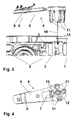
- Fig. 3
- als Detail eine Seitenansicht des Trägers und eines Teils des Gehäuses mit dem Fahrpedal (teilweise geschnitten) vor der Montage und
- Fig. 4
- eine Draufsicht auf den Träger gemäß
Figur 3
- Fig. 1
- a perspective view of a housing of an accelerator pedal with shaft and mounted support
- Fig. 2
- a lid with built-in circuit board for the housing
- Fig. 3
- as a detail, a side view of the carrier and a part of the housing with the accelerator pedal (partially cut) before mounting and
- Fig. 4
- a plan view of the carrier according to
FIG. 3 ,
Wie aus der
Auf einem Ende der Welle 3 ist ein Träger 4 befestigt, der aus den
Ein zweites Ende des Trägers 4, das der Welle 3 zugeordnet ist, ist in der Draufsicht kreisförmig. An der den Schleiferfedern 6 gegenüberliegenden Seite des Trägers 4 sind an dem zweiten Ende vier Rastfedern 11 angeordnet, die an ihren Enden jeweils einen Widerhaken aufweisen und mit entsprechenden Ausformungen der Welle 3 korrespondieren. Zentrisch auf dem zweiten Ende ist zwischen den Rastfedern 11 ein Kegelstumpfmantel- förmiger Zentrierdorn 12. Zwischen dem Zentrierdorn 12 und zwei gegenüberliegenden Rastfedern 11 ist jeweils eine Feder 13 als eine Erhebung gebildet, die in montiertem Zustand mit einer in eine Stirnseite der Welle 3 eingelassenen Nut 14 korrespondiert. Hierbei ist jeweils die Weite der Nut 14 geringfügig kleiner als die Dicke der Feder 13.A second end of the
Zwischen dem Arm 5 und dem zweiten Ende des Trägers 4 ist ein stumpfer Winkel so gebildet, dass das erste Ende leicht in Richtung der Rastfedern 11 abfällt. Hierdurch ist der Arm 5 gegen die Welle 3 geneigt, wenn er auf diese aufgesetzt ist. Wenn der Träger 4 in dem Gehäuse 1 auf der Welle 3 montiert ist, geht die Neigung gegen Null und kann je nach axialem Spiel von der Welle 3 und von dem Träger 4 negativ sein; das heißt, der Arm 5 ist leicht von den Rasfedern 11 weg geneigt.Between the
In einem Übergangsbereich zwischen dem zweiten Ende des Trägers 4 und dem Arm 5 ist eine relativ biegeweiche Stelle ausgebildet, wobei die Biegung um eine Achse in der Ebene des Arms 5 quer zu dessen Längsachse ermöglicht ist. Hierfür ist in diesem Bereich einerseits keine Verstärkungsrippe an dem Außenumfang des Arms 5, und der Längsschnitt des Arms 5 ist bogenförmig verjüngt. Andererseits bewirkt die Aussparung 7 eine Verringerung der Steifheit.In a transition region between the second end of the
Zum Verschließen des Gehäuses 1 ist ein Deckel 15 angeordnet, der in der
Zur Montage wird der Träger 4 mit den Rastarmen 11 über das entsprechende Ende der Welle 3 gedrückt (in
Der so montierte Drehsensor ist fertig für einen Einbau in ein Kraftfahrzeug.The rotation sensor mounted in this way is ready for installation in a motor vehicle.
- 11
- Gehäusecasing
- 22
- Fahrpedalaccelerator
- 33
- Wellewave
- 44
- Trägercarrier
- 55
- Armpoor
- 66
- Schleiferfederbrush spring
- 77
- Aussparungrecess
- 88th
- Stegweb
- 99
- Gleitstegsliding bridge
- 1010
- Gleitbahnslipway
- 1111
- Rastfederdetent spring
- 1212
- Zentrierdorncentering
- 1313
- Federfeather
- 1414
- Nutgroove
- 1515
- Deckelcover
- 1616
- Leiterplattecircuit board
- 1717
- Steckbuchsereceptacle
- 1818
- Pfeilarrow
Claims (4)
mit einem Gehäuse (1),
mit einem Träger (4), der auf einer Welle (3) eines drehbar gelagerten Hebels (2) befestigbar ist und auf dem die Schleiferfedern (6) befestigt sind,
und mit einer Leiterplatte (16), auf der den Schleiferfedern (6) zugeordnete Schleiferbahnen angeordnet sind,
dadurch gekennzeichnet, dass der Träger (4) mit der Welle (3) axial verrastet ist, wobei eine spielfreie Verdrehsicherung zur Verhinderung radialer Verschiebungen zwischen der Welle (3) und dem Träger (4) angeordnet ist.Rotary sensor with wiper springs,
with a housing (1),
with a carrier (4) which can be fastened on a shaft (3) of a rotatably mounted lever (2) and on which the wiper springs (6) are fastened,
and with a printed circuit board (16), on which the slider springs (6) associated with scooter tracks are arranged,
characterized in that the carrier (4) with the shaft (3) is axially locked, wherein a backlash-free rotation to prevent radial displacements between the shaft (3) and the carrier (4) is arranged.
Applications Claiming Priority (1)
| Application Number | Priority Date | Filing Date | Title |
|---|---|---|---|
| DE200710046787 DE102007046787B4 (en) | 2007-09-29 | 2007-09-29 | Rotary sensor with wiper springs |
Publications (2)
| Publication Number | Publication Date |
|---|---|
| EP2042840A2 true EP2042840A2 (en) | 2009-04-01 |
| EP2042840A3 EP2042840A3 (en) | 2014-07-09 |
Family
ID=40189618
Family Applications (1)
| Application Number | Title | Priority Date | Filing Date |
|---|---|---|---|
| EP08165265.3A Ceased EP2042840A3 (en) | 2007-09-29 | 2008-09-26 | Rotation sensor with slide clips |
Country Status (2)
| Country | Link |
|---|---|
| EP (1) | EP2042840A3 (en) |
| DE (1) | DE102007046787B4 (en) |
Cited By (1)
| Publication number | Priority date | Publication date | Assignee | Title |
|---|---|---|---|---|
| CN112362920A (en) * | 2020-11-11 | 2021-02-12 | 贵州电网有限责任公司 | State monitoring sensor protection device |
Families Citing this family (1)
| Publication number | Priority date | Publication date | Assignee | Title |
|---|---|---|---|---|
| DE102013114140A1 (en) * | 2013-12-16 | 2015-06-18 | Endress + Hauser Wetzer Gmbh + Co. Kg | Sensor housing and sensor arrangement with a sensor housing |
Citations (1)
| Publication number | Priority date | Publication date | Assignee | Title |
|---|---|---|---|---|
| EP0818666B1 (en) | 1996-07-09 | 2002-10-02 | Hella KG Hueck & Co. | Variable resistance rotation sensor |
Family Cites Families (13)
| Publication number | Priority date | Publication date | Assignee | Title |
|---|---|---|---|---|
| US2922043A (en) * | 1960-01-19 | Tuker assembly | ||
| DE3536833A1 (en) * | 1985-10-16 | 1987-04-16 | Novotechnik Gmbh Messwertaufne | Coupling for transmitting rotational movements without play, in particular for high-precision rotary potentiometers, and method for manufacturing it |
| DE3536931A1 (en) * | 1985-10-17 | 1987-04-23 | Basf Ag | AQUEOUS COPOLYMERISAT DISPERSIONS CONTAINING TERPENES |
| DE3624640A1 (en) * | 1986-07-22 | 1988-01-28 | Ruf Kg Wilhelm | ROTATION POTENTIOMETERS, ESPECIALLY FOR USE AS A ROTATIONAL SENSOR FOR THE ROTATION OF A SHAFT |
| US4973188A (en) * | 1989-07-10 | 1990-11-27 | Chrysler Corporation | Pointer bushing |
| DE4028931A1 (en) * | 1990-09-12 | 1992-03-19 | Bosch Gmbh Robert | ROTARY ENCODER |
| JP2000193412A (en) * | 1998-12-24 | 2000-07-14 | Alps Electric Co Ltd | Rotary sensor |
| JP2000292118A (en) * | 1999-04-12 | 2000-10-20 | Alps Electric Co Ltd | Angle of rotation sensor |
| JP3612242B2 (en) * | 1999-06-21 | 2005-01-19 | アルプス電気株式会社 | Rotation type sensor |
| EP1273889A1 (en) * | 2001-07-02 | 2003-01-08 | CTS Corporation | Rotational sensor |
| JP2003303532A (en) * | 2002-04-09 | 2003-10-24 | Alps Electric Co Ltd | Combined operation type electric component |
| JP4291014B2 (en) * | 2002-11-14 | 2009-07-08 | アルプス電気株式会社 | Rotation type sensor |
| JP2005351757A (en) * | 2004-06-10 | 2005-12-22 | Alps Electric Co Ltd | Rotation type sensor |
-
2007
- 2007-09-29 DE DE200710046787 patent/DE102007046787B4/en active Active
-
2008
- 2008-09-26 EP EP08165265.3A patent/EP2042840A3/en not_active Ceased
Patent Citations (1)
| Publication number | Priority date | Publication date | Assignee | Title |
|---|---|---|---|---|
| EP0818666B1 (en) | 1996-07-09 | 2002-10-02 | Hella KG Hueck & Co. | Variable resistance rotation sensor |
Cited By (2)
| Publication number | Priority date | Publication date | Assignee | Title |
|---|---|---|---|---|
| CN112362920A (en) * | 2020-11-11 | 2021-02-12 | 贵州电网有限责任公司 | State monitoring sensor protection device |
| CN112362920B (en) * | 2020-11-11 | 2023-01-24 | 贵州电网有限责任公司 | State monitoring sensor protection device |
Also Published As
| Publication number | Publication date |
|---|---|
| EP2042840A3 (en) | 2014-07-09 |
| DE102007046787A1 (en) | 2009-04-02 |
| DE102007046787B4 (en) | 2014-05-15 |
Similar Documents
| Publication | Publication Date | Title |
|---|---|---|
| EP1784318B1 (en) | Device for installing a sensor | |
| DE102008003296B4 (en) | accelerator | |
| EP1428714B1 (en) | Accelerator pedal module | |
| EP0254252B1 (en) | Rotary potentiometer, in particular for use as an angular position sensor for the rotary positioning of a shaft | |
| EP2154358B1 (en) | Air filter system for an automobile | |
| EP1681193B1 (en) | Air outlet nozzle, especially for a vehicle | |
| DE602004003077T2 (en) | A method for adjusting the range of motion of a worm shaft, adjusting a range of movement of a worm shaft and elastic holding device for an electric power steering | |
| DE3618927A1 (en) | DEVICE FOR DETERMINING THE THROTTLE VALVE POSITION FOR THE MACHINE OF A VEHICLE | |
| DE102012105963A1 (en) | Rotation angle sensor | |
| DE102012105966A1 (en) | Rotation angle sensor | |
| WO2018046394A1 (en) | Pedal, in particular accelerator pedal | |
| EP2099646A1 (en) | Steering-column switch for motor vehicles | |
| DE10065329B4 (en) | Accelerator with attachment to pedal arm | |
| DE2830518C2 (en) | Level sensor, in particular for measuring the tank content in motor vehicles | |
| DE102007046787B4 (en) | Rotary sensor with wiper springs | |
| DE3714348C2 (en) | ||
| EP1949041B1 (en) | Acceleration sensor | |
| EP3938238A1 (en) | Seat adjustment switch | |
| DE202017105338U1 (en) | angle converter | |
| EP1783034A2 (en) | Steering angle / steering torque sensor | |
| EP0814488B1 (en) | Position sensor | |
| EP3194893B1 (en) | Displacement sensor for a motor vehicle | |
| DE60033777T2 (en) | Subassembly for a potentiometric position sensor | |
| DE102020114733A1 (en) | Electronics for a vehicle and vehicle | |
| DE102020004421A1 (en) | Cylinder head with camshaft sensor |
Legal Events
| Date | Code | Title | Description |
|---|---|---|---|
| PUAI | Public reference made under article 153(3) epc to a published international application that has entered the european phase |
Free format text: ORIGINAL CODE: 0009012 |
|
| AK | Designated contracting states |
Kind code of ref document: A2 Designated state(s): AT BE BG CH CY CZ DE DK EE ES FI FR GB GR HR HU IE IS IT LI LT LU LV MC MT NL NO PL PT RO SE SI SK TR |
|
| AX | Request for extension of the european patent |
Extension state: AL BA MK RS |
|
| PUAL | Search report despatched |
Free format text: ORIGINAL CODE: 0009013 |
|
| AK | Designated contracting states |
Kind code of ref document: A3 Designated state(s): AT BE BG CH CY CZ DE DK EE ES FI FR GB GR HR HU IE IS IT LI LT LU LV MC MT NL NO PL PT RO SE SI SK TR |
|
| AX | Request for extension of the european patent |
Extension state: AL BA MK RS |
|
| RIC1 | Information provided on ipc code assigned before grant |
Ipc: G01D 11/18 20060101AFI20140605BHEP Ipc: G01D 11/24 20060101ALI20140605BHEP |
|
| 17P | Request for examination filed |
Effective date: 20140916 |
|
| RBV | Designated contracting states (corrected) |
Designated state(s): AT BE BG CH CY CZ DE DK EE ES FI FR GB GR HR HU IE IS IT LI LT LU LV MC MT NL NO PL PT RO SE SI SK TR |
|
| RBV | Designated contracting states (corrected) |
Designated state(s): AT BE BG CH CY CZ DE DK EE ES FI FR GB GR HR HU IE IS IT LI LT LU LV MC MT NL NO PL PT RO SE SI SK TR |
|
| RBV | Designated contracting states (corrected) |
Designated state(s): AT BE BG CH CY CZ DE DK EE ES FI FR GB GR HR HU IE IS IT LI LT LU LV MC MT NL NO PL PT RO SE SI SK TR |
|
| AKX | Designation fees paid |
Designated state(s): AT BE BG CH CY CZ DE DK EE ES FI FR GB GR HR HU IE IS IT LI LT LU LV MC MT NL NO PL PT RO SE SI SK TR |
|
| AXX | Extension fees paid |
Extension state: MK Extension state: RS Extension state: BA Extension state: AL |
|
| 17Q | First examination report despatched |
Effective date: 20150706 |
|
| STAA | Information on the status of an ep patent application or granted ep patent |
Free format text: STATUS: THE APPLICATION HAS BEEN REFUSED |
|
| 18R | Application refused |
Effective date: 20161218 |