EP2042823A1 - Home refrigerator with a cooled-drink dispenser - Google Patents
Home refrigerator with a cooled-drink dispenser Download PDFInfo
- Publication number
- EP2042823A1 EP2042823A1 EP07117393A EP07117393A EP2042823A1 EP 2042823 A1 EP2042823 A1 EP 2042823A1 EP 07117393 A EP07117393 A EP 07117393A EP 07117393 A EP07117393 A EP 07117393A EP 2042823 A1 EP2042823 A1 EP 2042823A1
- Authority
- EP
- European Patent Office
- Prior art keywords
- closed container
- supply pipe
- water
- beverage
- refrigerator
- Prior art date
- Legal status (The legal status is an assumption and is not a legal conclusion. Google has not performed a legal analysis and makes no representation as to the accuracy of the status listed.)
- Withdrawn
Links
Images

Classifications
-
- F—MECHANICAL ENGINEERING; LIGHTING; HEATING; WEAPONS; BLASTING
- F25—REFRIGERATION OR COOLING; COMBINED HEATING AND REFRIGERATION SYSTEMS; HEAT PUMP SYSTEMS; MANUFACTURE OR STORAGE OF ICE; LIQUEFACTION SOLIDIFICATION OF GASES
- F25D—REFRIGERATORS; COLD ROOMS; ICE-BOXES; COOLING OR FREEZING APPARATUS NOT OTHERWISE PROVIDED FOR
- F25D23/00—General constructional features
- F25D23/12—Arrangements of compartments additional to cooling compartments; Combinations of refrigerators with other equipment, e.g. stove
- F25D23/126—Water cooler
Definitions
- the present invention relates to a home refrigerator with a cooled-drink dispenser.
- the present invention relates to a home refrigerator with a cooled-water dispenser, to which the following description refers purely by way of example.
- cooled-drink dispenser built into the door to dispense, on command, cooled water at a temperature normally ranging between +5°C and +13°C.
- the cooled-drink dispenser normally comprises a tank filled manually by the user with the water or other beverage to be dispensed; and a metering valve located at a recess formed in the outer surface of the refrigerator door.
- the recess is designed to house a drinking glass or similar container, and the metering valve is connected to the bottom of the tank by a connecting pipe, and is designed to only permit controlled outflow of the water or other beverage from the tank into the beverage dispensing recess underneath, when the recess is engaged by a drinking glass or other container to receive the beverage.
- the tank may be cooled by the cold air circulating inside the refrigeration compartment of the refrigerator, or by an auxiliary heat exchanger integrated into the heat-pump cooling circuit of the refrigerator.
- the tank is housed inside the refrigeration compartment of the refrigerator, so that the cold air circulating inside the compartment flows over the walls of the tank.
- the cooling circuit of the refrigerator has an auxiliary evaporator surrounding and/or extending through the tank, so that the refrigerant withdraws heat directly from the water or other beverage inside the tank.
- the water tank may obviously also be surrounded by and/or fitted through with a portion of the main evaporator of the refrigerator cooling circuit.
- the temperature of the water in the tank depends on the temperature maintained inside the refrigeration compartment by the cooling circuit of the refrigerator; whereas, in the second solution, the cooling circuit of the refrigerator is capable of maintaining the tank at a predetermined reference temperature, regardless and independently of the temperature maintained inside the refrigeration compartment/s of the refrigerator.
- the inside of the tank is an ideal receptacle for uncontrolled formation of mould and bacteria, with all the drawbacks this entails in the event the cooled-drink dispenser is only used sporadically, and the water or other beverage is left standing inside the tank for a prolonged period of time.
- cooled-drink dispensers have been designed, in which the water tank is replaced by a small-diameter water supply pipe extending through a container filled with glycol or salt water.
- the water supply pipe is connected at one end to the metering valve, and at the other end to the water network supplying pressurized drinking water.
- the airtight container is cooled by the refrigerator cooling circuit, so that heat is withdrawn directly from the glycol or salt water inside the container to maintain the glycol or salt water at a temperature below 0°C.
- the drinking water flowing inside the water supply pipe releases heat to the glycol or salt water inside the airtight container.
- the amount of cooled water immediately dispensable is much smaller than in the conventional tank solution, but the risk of contamination by mould and bacteria is greatly reduced, by the inside of the water supply pipe being rinsed each time cooled water is drawn off.
- Patent Application WO-02/060806 describes a stand-alone cooled-drink dispenser, in which the water tank is connected directly to the water network supplying pressurized drinking water, and is maintained at a given temperature by the evaporator of a special heat-pump cooling circuit.
- the water tank has means for carbonating the water inside, and is fitted through with a small-diameter water supply pipe, which is connected at one end to the metering valve, and at the other end to the water network supplying pressurized drinking water, and forms a coil inside the tank to maximize heat exchange with the carbonated water in the tank.
- the metering valve is supplied with both cold carbonated water from the tank, and cold still water from the water supply pipe (i.e. from the water network), and is designed to dispense either one or a combination of both types of cooled water into the glass, as required by the user.
- a home refrigerator as claimed in Claim 1 and preferably, though not necessarily, in any one of the dependent Claims.
- number 1 indicates as a whole a home refrigerator particularly suitable for both preserving and freezing perishable foodstuffs, and which comprises at least two independent refrigeration compartments, each maintained at a predetermined reference temperature preferably, though not necessarily, differing from that of the other compartment.
- refrigerator 1 comprises a rigid, self-supporting, substantially parallelepiped-shaped casing 2 having two superimposed internal refrigeration compartments 3 and 4, each of which is lined with thermally insulating material and communicates with the outside through a respective access opening formed in the vertical front wall of casing 2.
- Refrigerator 1 also comprises two doors 5 and 6 hinged, one over the other, to the vertical front wall of casing 2 to rotate, about a preferably, though not necessarily, common vertical axis, to and from a closed position, in which each of the two doors rests against the vertical front wall of casing 2 to close the access opening to, and hermetically seal from the outside, a respective refrigeration compartment 3, 4.
- refrigerator 1 also comprises a heat-pump cooling circuit 7 (shown partly in Figure 1 ) which transfers heat from one fluid to another by exploiting the changes in state of an intermediate gas refrigerant subjected to a closed thermodynamic cycle, and which is designed to bring each refrigeration compartment 3, 4 to, and keep it at, a respective predetermined reference temperature normally lower than the outside temperature.
- a heat-pump cooling circuit 7 shown partly in Figure 1 ) which transfers heat from one fluid to another by exploiting the changes in state of an intermediate gas refrigerant subjected to a closed thermodynamic cycle, and which is designed to bring each refrigeration compartment 3, 4 to, and keep it at, a respective predetermined reference temperature normally lower than the outside temperature.
- the reference temperature may be user-selected from a predetermined range.
- heat-pump cooling circuit 7 is designed to keep refrigeration compartment 3 (i.e. the top compartment of the refrigerator) at a reference temperature ranging between +1°C and +10°C and preferably, though not necessarily, between +2°C and +8°C, so refrigeration compartment 3 is suitable for preserving non-freezable perishable foodstuffs; and to keep refrigeration compartment 4 (i.e. the bottom compartment of the refrigerator) at a lower reference temperature than refrigeration compartment 3 (i.e. below 0°C) and preferably, though not necessary, ranging between -2°C and -20°C, so refrigeration compartment 4 is suitable for freezing perishable foodstuffs and/or producing ice.
- top refrigeration compartment 3 constitutes the "fresh-food compartment”
- bottom refrigeration compartment 4 the "frozen-food compartment” of refrigerator 1.
- refrigerator 1 also comprises a cooled-drink dispenser 8 for controlled supply of cooled water or other beverage at a given temperature above 0°C and preferably, though not necessarily, ranging between +5°C and +13°C.
- cooled-drink dispenser 8 is integrated in the upper door 5 of refrigerator 1.
- cooled-drink dispenser 8 may also be located on the vertical front wall of casing 2, beside the upper 5 or lower door 6 of refrigerator 1.
- Cooled-drink dispenser 8 substantially comprises a preferably, though not necessarily, parallelepiped-shaped closed container 9; a small-diameter water supply pipe 10 extending through closed container 9, and having a first end connected to the drinking water network to receive drinking water at higher than atmospheric pressure; and a draw valve 11 which is housed in a drink dispensing recess 5a formed in the outer surface of top door 5, is connected to the second end of water supply pipe 10, and is designed to only permit controlled outflow of water from water supply pipe 10 to recess 5a when recess 5a is engaged by a drinking glass or other container to receive the water.
- closed container 9 is permanently filled with water, and is housed inside refrigeration compartment 3, i.e. the fresh-food compartment 3 of refrigerator 1, so that the cold air circulating in refrigeration compartment 3 flows over the outer surfaces of closed container 9 to cool and keep the stagnant water stored in closed container 9 at the reference temperature of fresh-food compartment 3 of refrigerator 1; whereas the central portion of water supply pipe 10 is coiled to form, in closed container 9, at least one pipe-coil 10a (two in the example shown) fully immersed in the stagnant water in closed container 9 so as to maximize heat exchange between the stagnant water stored in closed container 9 and the drinking water flowing in water supply pipe 10.
- closed container 9 is a sealed container designed to rest on a grille or perforated shelf 9a fixed horizontally, inside fresh-food compartment 3 of refrigerator 1, next to the fan for circulating the air in fresh-food compartment 3 and blowing it to the evaporator of heat-pump cooling circuit 7.
- closed container 9 comprises a substantially parallelepiped-, cup-shaped receptacle 12 closed by a substantially rectangular tray or panel 13 having a through hole 13a for water filling; and a sealing plug 14 fitted in easily removable manner inside through hole 13a to seal hole 13a, i.e. cup-shaped receptacle 12.
- receptacle 12 and panel 13 are made of rigid plastic, whereas sealing plug 14 is made of cork, rubber, silicone or similar elastic materials.
- Water supply pipe 10 comprises a flexible pipe 10 made of rubber, silicone or other elastically deformable plastic material, and of a nominal diameter preferably, though not necessarily, ranging between 6 and 15 millimetres.
- water supply pipe 10 is preferably, though not necessarily, sized so that the internal volume of water supply pipe 10 - or at least of the coiled central portion of water supply pipe 10 housed in closed container 9, i.e. the two pipe-coils 10a - approximately equals a quarter of the internal volume of closed container 9.
- volumetric ratio between the total internal volume or capacity of closed container 9 and the total internal volume or capacity of water supply pipe 10, or at least one pipe-coil 10a must range between 5 and 3.
- closed container 9 should have a capacity of approximately 4 litres, and water supply pipe 10 a capacity of approximately 1 litre.
- cooled-drink dispenser 8 preferably, though not necessarily, also comprises an on-off valve (not shown) located between water supply pipe 10 and the drinking water network, and which, on command, isolates water supply pipe 10 from the drinking water network to cut off drinking water supply.
- an on-off valve located between water supply pipe 10 and the drinking water network, and which, on command, isolates water supply pipe 10 from the drinking water network to cut off drinking water supply.
- the drinking water network is defined by the water mains of the building in which refrigerator 1 is located, and the on-off valve (not shown) is a conventional on-off solenoid valve preferably, though not necessarily, controlled by draw valve 11.
- draw valve 11 is also a commonly known part in the industry, and therefore not described in detail.
- insertion of a glass inside recess 5a in door 5 opens draw valve 11 to allow the cooled drinking water in water supply pipe 10 to fall into the glass.
- Water supply pipe 10 being connected directly to the drinking water network, outflow of cooled drinking water from water supply pipe 10 is accompanied by simultaneous inflow into water supply pipe 10 of an equal amount of drinking water at ambient temperature from the drinking water network.
- the drinking water at ambient temperature from the water network cools rapidly by releasing heat to the stagnant water stored in closed container 9, and reaches a desired temperature of +5°C to +13°C by the time it comes out of water supply pipe 10.
- closed container 9 is permanently filled with the same quantity of stagnant water at the reference temperature of fresh-food compartment 3 ensures that the drinking water at ambient temperature flowing in water supply pipe 10 always releases the same amount of heat to the stagnant water stored in closed container 9, and therefore always undergoes the same temperature drop.
- refrigerator 1 features a heat-pump cooling circuit 7 identical to that of a conventional refrigerator, thus greatly reducing manufacturing cost.
- Housing the sealed container 9 inside fresh-food compartment 3 also prevents conversion of the stagnant water in sealed container 9 to ice, thus increasing in volume and irreparably damaging sealed container 9.
- cooled-drink dispenser 8 involves practically no risk of contamination by mould or bacteria, with all the advantages this entails.
- a chemical bactericide may be dissolved in the stagnant water in sealed container 9 to prevent the spread of mould or bacteria inside sealed container 9.
- water supply pipe 10 may be connected to a pressurized-beverage source other than the water network, such as a pressurized-beverage tank or drum.
Abstract
Description
- The present invention relates to a home refrigerator with a cooled-drink dispenser.
- More specifically, the present invention relates to a home refrigerator with a cooled-water dispenser, to which the following description refers purely by way of example.
- As is known, some home refrigerator models have a cooled-drink dispenser built into the door to dispense, on command, cooled water at a temperature normally ranging between +5°C and +13°C.
- The cooled-drink dispenser normally comprises a tank filled manually by the user with the water or other beverage to be dispensed; and a metering valve located at a recess formed in the outer surface of the refrigerator door. The recess is designed to house a drinking glass or similar container, and the metering valve is connected to the bottom of the tank by a connecting pipe, and is designed to only permit controlled outflow of the water or other beverage from the tank into the beverage dispensing recess underneath, when the recess is engaged by a drinking glass or other container to receive the beverage.
- Depending on where it is located inside the refrigerator, the tank may be cooled by the cold air circulating inside the refrigeration compartment of the refrigerator, or by an auxiliary heat exchanger integrated into the heat-pump cooling circuit of the refrigerator.
- More specifically, in the first case, the tank is housed inside the refrigeration compartment of the refrigerator, so that the cold air circulating inside the compartment flows over the walls of the tank.
- In the second case, the cooling circuit of the refrigerator has an auxiliary evaporator surrounding and/or extending through the tank, so that the refrigerant withdraws heat directly from the water or other beverage inside the tank. The water tank may obviously also be surrounded by and/or fitted through with a portion of the main evaporator of the refrigerator cooling circuit.
- Obviously, in the first solution, the temperature of the water in the tank depends on the temperature maintained inside the refrigeration compartment by the cooling circuit of the refrigerator; whereas, in the second solution, the cooling circuit of the refrigerator is capable of maintaining the tank at a predetermined reference temperature, regardless and independently of the temperature maintained inside the refrigeration compartment/s of the refrigerator.
- Location of the cooled-drink dispenser inside the refrigerator seriously limits the capacity of the tank and performance of the dispenser itself, which, in fact, cannot dispense the beverage at the desired temperature until the user fills the tank with the beverage, and the cooling circuit of the refrigerator cools the beverage in the tank to the set dispensing temperature.
- Moreover, the inside of the tank is an ideal receptacle for uncontrolled formation of mould and bacteria, with all the drawbacks this entails in the event the cooled-drink dispenser is only used sporadically, and the water or other beverage is left standing inside the tank for a prolonged period of time.
- To eliminate these drawbacks, cooled-drink dispensers have been designed, in which the water tank is replaced by a small-diameter water supply pipe extending through a container filled with glycol or salt water. The water supply pipe is connected at one end to the metering valve, and at the other end to the water network supplying pressurized drinking water.
- The airtight container is cooled by the refrigerator cooling circuit, so that heat is withdrawn directly from the glycol or salt water inside the container to maintain the glycol or salt water at a temperature below 0°C.
- As such, the drinking water flowing inside the water supply pipe releases heat to the glycol or salt water inside the airtight container.
- In the water supply pipe solution, the amount of cooled water immediately dispensable is much smaller than in the conventional tank solution, but the risk of contamination by mould and bacteria is greatly reduced, by the inside of the water supply pipe being rinsed each time cooled water is drawn off.
- Patent Application
WO-02/060806 - In this combination solution, which cannot be built into a home refrigerator because of insufficient space, the metering valve is supplied with both cold carbonated water from the tank, and cold still water from the water supply pipe (i.e. from the water network), and is designed to dispense either one or a combination of both types of cooled water into the glass, as required by the user.
- Building into the refrigerator a cooled-drink dispenser, in which the water tank is replaced by a coil or skein of small-diameter pipe connected directly to the external water network, however, seriously complicates the heat-pump cooling circuit of the refrigerator, thus greatly increasing manufacturing cost.
- It is an object of the present invention to provide a home refrigerator with a cooled-drink dispenser, which is cheaper to produce, and in which the cooled-drink dispenser involves no risk of contamination by mould or bacteria.
- According to the present invention, there is provided a home refrigerator as claimed in
Claim 1 and preferably, though not necessarily, in any one of the dependent Claims. - A non-limiting embodiment of the present invention will be described by way of example with reference to the accompanying drawings, in which:
-
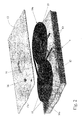
Figure 1 shows a view in axonometry, with semitransparent parts and parts removed for clarity, of the top portion of a home refrigerator in accordance with the teachings of the present invention; -
Figure 2 shows a partly exploded view in perspective of a component part of theFigure 1 refrigerator. - With reference to
Figure 1 ,number 1 indicates as a whole a home refrigerator particularly suitable for both preserving and freezing perishable foodstuffs, and which comprises at least two independent refrigeration compartments, each maintained at a predetermined reference temperature preferably, though not necessarily, differing from that of the other compartment. - More specifically, in the example shown,
refrigerator 1 comprises a rigid, self-supporting, substantially parallelepiped-shaped casing 2 having two superimposedinternal refrigeration compartments casing 2. -
Refrigerator 1 also comprises twodoors casing 2 to rotate, about a preferably, though not necessarily, common vertical axis, to and from a closed position, in which each of the two doors rests against the vertical front wall ofcasing 2 to close the access opening to, and hermetically seal from the outside, arespective refrigeration compartment - With reference to
Figure 1 ,refrigerator 1 also comprises a heat-pump cooling circuit 7 (shown partly inFigure 1 ) which transfers heat from one fluid to another by exploiting the changes in state of an intermediate gas refrigerant subjected to a closed thermodynamic cycle, and which is designed to bring eachrefrigeration compartment - The reference temperature may be user-selected from a predetermined range.
- More specifically, in the example shown, heat-
pump cooling circuit 7 is designed to keep refrigeration compartment 3 (i.e. the top compartment of the refrigerator) at a reference temperature ranging between +1°C and +10°C and preferably, though not necessarily, between +2°C and +8°C, sorefrigeration compartment 3 is suitable for preserving non-freezable perishable foodstuffs; and to keep refrigeration compartment 4 (i.e. the bottom compartment of the refrigerator) at a lower reference temperature than refrigeration compartment 3 (i.e. below 0°C) and preferably, though not necessary, ranging between -2°C and -20°C, sorefrigeration compartment 4 is suitable for freezing perishable foodstuffs and/or producing ice. - In other words,
top refrigeration compartment 3 constitutes the "fresh-food compartment", andbottom refrigeration compartment 4 the "frozen-food compartment" ofrefrigerator 1. -
Casing 2,doors pump cooling circuit 7 are commonly known parts in the industry, and therefore not described in detail. - With reference to
Figures 1 and2 ,refrigerator 1 also comprises a cooled-drink dispenser 8 for controlled supply of cooled water or other beverage at a given temperature above 0°C and preferably, though not necessarily, ranging between +5°C and +13°C. - More specifically, in the example shown cooled-
drink dispenser 8 is integrated in theupper door 5 ofrefrigerator 1. Obviously, cooled-drink dispenser 8 may also be located on the vertical front wall ofcasing 2, beside the upper 5 orlower door 6 ofrefrigerator 1. - Cooled-
drink dispenser 8 substantially comprises a preferably, though not necessarily, parallelepiped-shaped closedcontainer 9; a small-diameterwater supply pipe 10 extending through closedcontainer 9, and having a first end connected to the drinking water network to receive drinking water at higher than atmospheric pressure; and adraw valve 11 which is housed in a drink dispensingrecess 5a formed in the outer surface oftop door 5, is connected to the second end ofwater supply pipe 10, and is designed to only permit controlled outflow of water fromwater supply pipe 10 to recess 5a whenrecess 5a is engaged by a drinking glass or other container to receive the water. - Unlike known solutions, closed
container 9 is permanently filled with water, and is housed insiderefrigeration compartment 3, i.e. the fresh-food compartment 3 ofrefrigerator 1, so that the cold air circulating inrefrigeration compartment 3 flows over the outer surfaces of closedcontainer 9 to cool and keep the stagnant water stored in closedcontainer 9 at the reference temperature of fresh-food compartment 3 ofrefrigerator 1; whereas the central portion ofwater supply pipe 10 is coiled to form, in closedcontainer 9, at least one pipe-coil 10a (two in the example shown) fully immersed in the stagnant water in closedcontainer 9 so as to maximize heat exchange between the stagnant water stored in closedcontainer 9 and the drinking water flowing inwater supply pipe 10. - More specifically, in the example shown, closed
container 9 is a sealed container designed to rest on a grille or perforatedshelf 9a fixed horizontally, inside fresh-food compartment 3 ofrefrigerator 1, next to the fan for circulating the air in fresh-food compartment 3 and blowing it to the evaporator of heat-pump cooling circuit 7. - More specifically, with reference to
Figure 2 , closedcontainer 9 comprises a substantially parallelepiped-, cup-shaped receptacle 12 closed by a substantially rectangular tray orpanel 13 having a throughhole 13a for water filling; and asealing plug 14 fitted in easily removable manner inside throughhole 13a to sealhole 13a, i.e. cup-shaped receptacle 12. In the example shown,receptacle 12 andpanel 13 are made of rigid plastic, whereassealing plug 14 is made of cork, rubber, silicone or similar elastic materials. -
Water supply pipe 10 comprises aflexible pipe 10 made of rubber, silicone or other elastically deformable plastic material, and of a nominal diameter preferably, though not necessarily, ranging between 6 and 15 millimetres. - In addition to the above,
water supply pipe 10 is preferably, though not necessarily, sized so that the internal volume of water supply pipe 10 - or at least of the coiled central portion ofwater supply pipe 10 housed in closedcontainer 9, i.e. the two pipe-coils 10a - approximately equals a quarter of the internal volume of closedcontainer 9. - In other words, the volumetric ratio between the total internal volume or capacity of closed
container 9 and the total internal volume or capacity ofwater supply pipe 10, or at least one pipe-coil 10a, must range between 5 and 3. - More specifically, closed
container 9 should have a capacity of approximately 4 litres, andwater supply pipe 10 a capacity of approximately 1 litre. - Finally, in the example shown, cooled-
drink dispenser 8 preferably, though not necessarily, also comprises an on-off valve (not shown) located betweenwater supply pipe 10 and the drinking water network, and which, on command, isolateswater supply pipe 10 from the drinking water network to cut off drinking water supply. - In the example shown, the drinking water network is defined by the water mains of the building in which
refrigerator 1 is located, and the on-off valve (not shown) is a conventional on-off solenoid valve preferably, though not necessarily, controlled bydraw valve 11. - Like
casing 2,doors pump cooling circuit 7,draw valve 11 is also a commonly known part in the industry, and therefore not described in detail. - General operation of
refrigerator 1 is clearly inferable from the above description. - As regards operation of cooled-
drink dispenser 8, insertion of a glass inside recess 5a indoor 5 opensdraw valve 11 to allow the cooled drinking water inwater supply pipe 10 to fall into the glass.Water supply pipe 10 being connected directly to the drinking water network, outflow of cooled drinking water fromwater supply pipe 10 is accompanied by simultaneous inflow intowater supply pipe 10 of an equal amount of drinking water at ambient temperature from the drinking water network. - As it flows along
water supply pipe 10, the drinking water at ambient temperature from the water network cools rapidly by releasing heat to the stagnant water stored in closedcontainer 9, and reaches a desired temperature of +5°C to +13°C by the time it comes out ofwater supply pipe 10. - The fact that closed
container 9 is permanently filled with the same quantity of stagnant water at the reference temperature of fresh-food compartment 3 ensures that the drinking water at ambient temperature flowing inwater supply pipe 10 always releases the same amount of heat to the stagnant water stored in closedcontainer 9, and therefore always undergoes the same temperature drop. - Since the temperature drop depends on the volume ratio between closed
container 9 and the portion ofwater supply pipe 10 housed in closedcontainer 9, i.e. the two pipe-coils 10a, appropriate adjustment of the volume ratio allows immediate supply into the glass of cooled drinking water at a constant given temperature ranging between +5°C and +13°C. - The advantages of cooled-
drink dispenser 8 are obvious. Despite comprising a cooled-drink dispenser 8,refrigerator 1 features a heat-pump cooling circuit 7 identical to that of a conventional refrigerator, thus greatly reducing manufacturing cost. - Housing the sealed
container 9 inside fresh-food compartment 3 also prevents conversion of the stagnant water in sealedcontainer 9 to ice, thus increasing in volume and irreparably damaging sealedcontainer 9. - Finally, cooled-
drink dispenser 8 involves practically no risk of contamination by mould or bacteria, with all the advantages this entails. - Clearly, changes may be made to
home refrigerator 1 as described herein without, however, departing from the scope of the present invention. - For example, a chemical bactericide may be dissolved in the stagnant water in sealed
container 9 to prevent the spread of mould or bacteria inside sealedcontainer 9. - In a different embodiment,
water supply pipe 10 may be connected to a pressurized-beverage source other than the water network, such as a pressurized-beverage tank or drum.
Claims (12)
- A home refrigerator (1) comprising a fresh-food compartment (3) for preserving food, a cooling circuit (7) designed to keep said fresh-food compartment (3) at a reference temperature ranging between +1°C and +10°C, and a cooled-drink dispenser (8) for controlled supply of a cooled beverage at a given temperature; the cooled-drink dispenser (8) comprising a closed container (9), and a beverage supply pipe (10) extending through said closed container (9) and having a first end connected to a beverage source supplying water or other beverage at a given pressure higher than atmospheric pressure; the cooled-drink dispenser (8) also comprising a draw device (11) for controlling outflow of the water or other beverage from the beverage supply pipe (10) into a generic glass or receptacle, and said beverage supply pipe (10) having a second end connected to said draw device (11); the refrigerator (1) being characterized in that the closed container (9) is permanently filled with liquid, and is housed inside said fresh-food compartment (3) so that the cold air circulating in the fresh-food compartment (3) flows over the outer surfaces of the closed container (9) to cool the liquid stored in said closed container (9); the central portion of said beverage supply pipe (10) being coiled to form, in said closed container (9), at least one pipe-coil (10a) fully immersed in the liquid in said closed container (9).
- A home refrigerator as claimed in Claim 1,
characterized in that the liquid in said closed container (9) is water. - A home refrigerator as claimed in any one of the foregoing Claims, characterized in that said closed container (9) is a substantially parallelepiped-shaped container (9), and is designed to be placed horizontally inside said fresh-food compartment (3).
- A home refrigerator as claimed in any one of the foregoing Claims, characterized in that said closed container (9) is arranged in an upper side of said fresh-food compartment.
- A home refrigerator as claimed in any one of the foregoing Claims, characterized in that said closed container (9) is made of plastic.
- A home refrigerator as claimed in any one of the foregoing Claims, characterized in that said closed container (9) is an airtight closed container (9).
- A home refrigerator as claimed in any one of the foregoing Claims, characterised in that said beverage supply pipe (10) is a flexible pipe (10) made of rubber, silicone or other elastically deformable plastic material.
- A home refrigerator as claimed in any one of the foregoing Claims, characterized in that said beverage supply pipe (10) has a nominal diameter ranging between 6 and 15 millimetres.
- A home refrigerator as claimed in any one of the foregoing Claims, characterized in that the volume ratio between the internal volume of the closed container (9) and the internal volume of said at least one pipe-coil (10a) of the beverage supply pipe (10) ranges between 5 and 3.
- A home refrigerator as claimed in any one of the foregoing Claims, characterized in that said draw device (11) for controlling outflow of the water or other beverage from the beverage supply pipe (10) comprises a draw valve (11) which is housed in a drink dispensing recess (5a) formed in a door (5) of the refrigerator (1), is connected to the second end of said beverage supply pipe (10), and is designed to only permit controlled outflow of the water or other beverage from the beverage supply pipe (10) to said drink dispensing recess (5a) when the recess (5a) is engaged by a drinking glass or other container.
- A home refrigerator as claimed in any one of the foregoing Claims, characterized in that said cooling circuit (7) is a heat-pump cooling circuit (7).
- A home refrigerator as claimed in any one of the foregoing Claims, characterized in that said beverage source is the water mains of the building in which the refrigerator (1) is located.
Priority Applications (2)
| Application Number | Priority Date | Filing Date | Title |
|---|---|---|---|
| EP07117393A EP2042823A1 (en) | 2007-09-27 | 2007-09-27 | Home refrigerator with a cooled-drink dispenser |
| PCT/EP2008/007402 WO2009039956A1 (en) | 2007-09-27 | 2008-09-10 | Home refrigerator with a cooled-drink dispenser |
Applications Claiming Priority (1)
| Application Number | Priority Date | Filing Date | Title |
|---|---|---|---|
| EP07117393A EP2042823A1 (en) | 2007-09-27 | 2007-09-27 | Home refrigerator with a cooled-drink dispenser |
Publications (1)
| Publication Number | Publication Date |
|---|---|
| EP2042823A1 true EP2042823A1 (en) | 2009-04-01 |
Family
ID=39246846
Family Applications (1)
| Application Number | Title | Priority Date | Filing Date |
|---|---|---|---|
| EP07117393A Withdrawn EP2042823A1 (en) | 2007-09-27 | 2007-09-27 | Home refrigerator with a cooled-drink dispenser |
Country Status (2)
| Country | Link |
|---|---|
| EP (1) | EP2042823A1 (en) |
| WO (1) | WO2009039956A1 (en) |
Citations (7)
| Publication number | Priority date | Publication date | Assignee | Title |
|---|---|---|---|---|
| US1994698A (en) * | 1931-08-24 | 1935-03-19 | Jr Adolph F Evers | Water cooling device |
| DE652286C (en) * | 1934-04-14 | 1937-10-28 | Rudolf Brecht | Beer served with a fridge |
| FR1019999A (en) * | 1950-06-09 | 1953-01-30 | Method and device for cooling liquids, in particular by means of refrigerated cabinets | |
| US3429140A (en) * | 1968-02-09 | 1969-02-25 | Gen Electric | Household refrigerator including ice and water dispensing means |
| US3462970A (en) * | 1968-03-18 | 1969-08-26 | Howard Natter | Portable soda fountain |
| FR2549586A1 (en) * | 1983-07-20 | 1985-01-25 | Lanteri Guy | Device for refrigerating drinks or the like which is removable and can be fitted to any refrigeration cabinet. |
| US20040183414A1 (en) * | 2003-03-22 | 2004-09-23 | Lg Electronics Inc. | Refrigerator door having dispenser |
-
2007
- 2007-09-27 EP EP07117393A patent/EP2042823A1/en not_active Withdrawn
-
2008
- 2008-09-10 WO PCT/EP2008/007402 patent/WO2009039956A1/en active Application Filing
Patent Citations (7)
| Publication number | Priority date | Publication date | Assignee | Title |
|---|---|---|---|---|
| US1994698A (en) * | 1931-08-24 | 1935-03-19 | Jr Adolph F Evers | Water cooling device |
| DE652286C (en) * | 1934-04-14 | 1937-10-28 | Rudolf Brecht | Beer served with a fridge |
| FR1019999A (en) * | 1950-06-09 | 1953-01-30 | Method and device for cooling liquids, in particular by means of refrigerated cabinets | |
| US3429140A (en) * | 1968-02-09 | 1969-02-25 | Gen Electric | Household refrigerator including ice and water dispensing means |
| US3462970A (en) * | 1968-03-18 | 1969-08-26 | Howard Natter | Portable soda fountain |
| FR2549586A1 (en) * | 1983-07-20 | 1985-01-25 | Lanteri Guy | Device for refrigerating drinks or the like which is removable and can be fitted to any refrigeration cabinet. |
| US20040183414A1 (en) * | 2003-03-22 | 2004-09-23 | Lg Electronics Inc. | Refrigerator door having dispenser |
Also Published As
| Publication number | Publication date |
|---|---|
| WO2009039956A1 (en) | 2009-04-02 |
Similar Documents
| Publication | Publication Date | Title |
|---|---|---|
| US20240092624A1 (en) | Single tank carbonation for carbonated soft drink equipment | |
| US8516849B2 (en) | Cooler and method for cooling beverage containers such as bottles and cans | |
| KR102357243B1 (en) | Versatile and aesthetically refined keg dispenser | |
| US9045260B2 (en) | Beverage dispensing system | |
| US20180057337A1 (en) | Mixed Drink Producing Apparatus With A Manipulation Device For Manipulating An Orientation Of A Jet Of A Liquid Of The Mixed Drink, Household Refrigeration Apparatus As Well As Method For Producing And Dispensing A Mixed Drink | |
| BR112016021850A2 (en) | APPLIANCE TO DISPENSING A DRINK | |
| US20110100049A1 (en) | Countermount, tapping apparatus and method for regulating the temperature of beverage | |
| EP1912032B1 (en) | Refrigeration appliance with a water dispenser | |
| US9828229B2 (en) | Refrigerator and beverage supplying method using the same | |
| KR20190109103A (en) | Device For Cooling Beverage | |
| US11326825B2 (en) | Stand-alone ice and beverage appliance | |
| JP2020532465A (en) | Methods and equipment for beverage dispensing systems | |
| JP3807958B2 (en) | Dispenser for soft drinks such as beer | |
| EP2042823A1 (en) | Home refrigerator with a cooled-drink dispenser | |
| CN216494874U (en) | Multifunctional refrigerator | |
| JP3600807B2 (en) | Dispenser for soft drinks such as beer | |
| US10260800B2 (en) | Mixed beverage production appliance, domestic refrigeration appliance containing such a mixed beverage production appliance and method for preparing a mixed beverage | |
| US20220026143A1 (en) | Stand-alone beverage dispenser and cooling system | |
| EP1139044B1 (en) | Refrigerator appliance with drink dispensing device | |
| US20070138205A1 (en) | On demand drink dispenser | |
| WO2010134801A1 (en) | Tapping apparatus and cooling circuit for a tapping apparatus | |
| JP2000220936A (en) | Cool drink supply | |
| JP2000234837A (en) | Raw beer cooling/extraction apparatus | |
| JPH0493574A (en) | Soft drink supplying machine | |
| WO2010018581A1 (en) | Apparatus for freezing and dispensing a beverage |
Legal Events
| Date | Code | Title | Description |
|---|---|---|---|
| PUAI | Public reference made under article 153(3) epc to a published international application that has entered the european phase |
Free format text: ORIGINAL CODE: 0009012 |
|
| AK | Designated contracting states |
Kind code of ref document: A1 Designated state(s): AT BE BG CH CY CZ DE DK EE ES FI FR GB GR HU IE IS IT LI LT LU LV MC MT NL PL PT RO SE SI SK TR |
|
| AX | Request for extension of the european patent |
Extension state: AL BA HR MK RS |
|
| 17P | Request for examination filed |
Effective date: 20090930 |
|
| 17Q | First examination report despatched |
Effective date: 20091030 |
|
| AKX | Designation fees paid |
Designated state(s): AT BE BG CH CY CZ DE DK EE ES FI FR GB GR HU IE IS IT LI LT LU LV MC MT NL PL PT RO SE SI SK TR |
|
| RAP1 | Party data changed (applicant data changed or rights of an application transferred) |
Owner name: ELECTROLUX HOME PRODUCTS CORPORATION N.V. |
|
| RAP1 | Party data changed (applicant data changed or rights of an application transferred) |
Owner name: ELECTROLUX HOME PRODUCTS CORPORATION N.V. |
|
| STAA | Information on the status of an ep patent application or granted ep patent |
Free format text: STATUS: THE APPLICATION IS DEEMED TO BE WITHDRAWN |
|
| 18D | Application deemed to be withdrawn |
Effective date: 20160401 |