EP2042804A2 - Suspended projector - Google Patents
Suspended projector Download PDFInfo
- Publication number
- EP2042804A2 EP2042804A2 EP08164682A EP08164682A EP2042804A2 EP 2042804 A2 EP2042804 A2 EP 2042804A2 EP 08164682 A EP08164682 A EP 08164682A EP 08164682 A EP08164682 A EP 08164682A EP 2042804 A2 EP2042804 A2 EP 2042804A2
- Authority
- EP
- European Patent Office
- Prior art keywords
- adapter
- casing
- rail
- projector
- mounted position
- Prior art date
- Legal status (The legal status is an assumption and is not a legal conclusion. Google has not performed a legal analysis and makes no representation as to the accuracy of the status listed.)
- Granted
Links
Images


Classifications
-
- F—MECHANICAL ENGINEERING; LIGHTING; HEATING; WEAPONS; BLASTING
- F21—LIGHTING
- F21V—FUNCTIONAL FEATURES OR DETAILS OF LIGHTING DEVICES OR SYSTEMS THEREOF; STRUCTURAL COMBINATIONS OF LIGHTING DEVICES WITH OTHER ARTICLES, NOT OTHERWISE PROVIDED FOR
- F21V21/00—Supporting, suspending, or attaching arrangements for lighting devices; Hand grips
- F21V21/34—Supporting elements displaceable along a guiding element
- F21V21/35—Supporting elements displaceable along a guiding element with direct electrical contact between the supporting element and electric conductors running along the guiding element
-
- F—MECHANICAL ENGINEERING; LIGHTING; HEATING; WEAPONS; BLASTING
- F21—LIGHTING
- F21V—FUNCTIONAL FEATURES OR DETAILS OF LIGHTING DEVICES OR SYSTEMS THEREOF; STRUCTURAL COMBINATIONS OF LIGHTING DEVICES WITH OTHER ARTICLES, NOT OTHERWISE PROVIDED FOR
- F21V23/00—Arrangement of electric circuit elements in or on lighting devices
- F21V23/02—Arrangement of electric circuit elements in or on lighting devices the elements being transformers, impedances or power supply units, e.g. a transformer with a rectifier
- F21V23/026—Fastening of transformers or ballasts
Definitions
- This invention relates to a suspended projector device.
- Projector devices mainly intended for inside illumination applications, that basically consist of a projector, which is coupled in an adjustable way to a casing and an adapter, are known.
- the adapter has a lower area that is attached to the casing, and a top connecting area that is inserted inside a rail allowing for the projector's sliding along said rail.
- the rail typically in aluminium and attached to the ceiling, has an interior profile with a configuration which is complementary to the exterior configuration of the top connecting area of the device adapter.
- the adapter top area allows for the projector electrical connection through said rail.
- an adjustable projector which is suspended from the rail and able to slide along it, allowing for adapting to illumination necessities.
- the object of this invention is to solve the drawbacks that the state of the art devices have, with a suspended projector device that includes a projector, a casing that houses electronic equipment in its interior, and an adapter that has a connecting top area for its insertion in the interior of a rail which allows for the projector sliding along said rail, and a lower area coupled to the projector device, so that, in operation, the projector device is suspended from the rail by means of said adapter and situated along it, said adapter remaining completely concealed in its mounted position, where its lower area is housed in said casing, and said adapter being able to move longitudinally in relation to said casing between its mounted position and a removal position, where the lower area of the adapter is not housed in the casing, characterized in that it includes automatic actuation means for the longitudinal movement from the mounted position to the removal position of said adapter in relation to said casing.
- a user can simply and rapidly fix the device according to the invention in a position where the adapter is visible so as to remove it from the rail or to carry out any other operation.
- the automatic actuation means include elastic means that tend to move said adapter away from said casing and actuation means of said elastic means away from the mounted position to the removal position.
- the elastic means include a compression spring associated to the lower area of the adapter at one end and the casing at the other.
- the actuation means of said elastic means include a push button.
- the push button is situated on the casing.
- the push button is associated to a locking piece that includes two positions, a first position that corresponds to the mounted position of the device, and a second position that corresponds to the removal position of the device.
- the locking piece in the first position, is coupled to a piece that is associated to the lower part of the adapter, thus locking the longitudinal movement between the casing and the adapter and maintaining the spring compressed and, in the second position, the locking piece is uncoupled from the piece that is associated to the lower part of the adapter allowing for the longitudinal movement between the casing and the adapter and for the spring to extend by moving the casing and the adapter away.
- the user can separate the casing and the adapter for the connection to the rail by simply pushing a push button, without making any effort.
- the spring automatically moves the casing, the adapter remaining visible.
- the device to return to its mounted position again, one has to simply push the casing upwards, till the lower part of the adapter is housed again in the interior of said casing.
- the device 1 basically includes a light projector 2, a casing 3 and an adapter 4.
- the projector 2 is attached to the casing 3 by means of an articulation that allows for convenient positioning.
- the casing 3 houses the electronic equipment of the projector device 1 (not shown).
- the device 1 also includes an adapter 4 that is used to mount the projector 2 and the casing 3 in a three-phase rail 5 made in aluminium (see figures 2 to 5 ) that is attached to a ceiling.
- the rail has a U-shaped cross section, with a grooved interior profile.
- the adapter 4 includes a top part 4a, that is inserted in the rail 5 and is removable, so that the adapter 4 can be fixed along the rail 5 and locked at the desired position.
- the adapter top area 4a includes some electric contacts that, in operation, are inside the rail 5 and allow for the electrical contact between the device 1 and the rail 5 independent of the relative position of both elements.
- a side lid 4c conceals and protects the interior of the top area 4a of the adapter 4.
- the adapter 4 also includes a lower part 4b, that is coupled to the rest of the projector device 1, as further described hereinafter.
- the adapter 4 and the rail 5 constitute standard elements for one skilled in the art, for this reason the operation and structure of the same will not be further explained.
- the projector device 1 of this invention includes a mechanism of automatic actuation 6 that allows for the longitudinal movement of said adapter 4 in relation to said casing 3 between the mounted position and removal position of said device 1.
- mounted position means a position where the top part 4b of the adapter 4 is housed in the interior of the casing 3, so that the adapter 4 is totally concealed when the device 1 is mounted in the rail 5 and in operation ( figure 2 ).
- Removal position means a position where the lower part 4b of the adapter 4 is located outside the casing 3 and is visible, allowing for mounting and removing the device 1 from the rail 5 ( figures 3 to 5 ).
- connection washer 7 and an ejection bush 8 are joined by means of a rivet 9, with a washer between the same, that allows the connection washer 7 to rotate 180 degrees in relation to the bush 8.
- a guiding top lid 10 that covers the casing 3 is held between the connection washer 7 and the bush 8.
- connection washer 7 is attached to the lower part 4b of the adapter 4, that rotates 180 degrees solidarily with said connection washer 7.
- An ejection shaft 11 is attached by means of two screws 12 to the ejection bush 8.
- a spring 13 is arranged by surrounding the lower end of the shaft 11, between two longitudinal ribs 14 of the shaft 11 and a lower cover 15. Said spring 13 tends to separate the group composed of the connection washer 7, the ejection bush 8, the rivet 9 and the shaft 11 in relation to the lower cover 15.
- a locking piece 16 is mounted between the lower cover 15 and the shaft 11, by surrounding the ribs 14.
- Said locking piece 16 includes two columns each one being associated to its spring 17 and is attached to a push button 18 at its opposite end by means of a screw.
- the locking piece 16 and the spring 17 are mounted inside the cover 15, with capacity of lateral movement in relation to the same.
- the locking piece 16 tends to be laterally ejected thanks to the action of said springs 17.
- the cover 15 is screwed to the lid 10 by means of two screws 19, so that the group of elements described is encapsulated.
- the lid 10 in turn, is attached to the casing 3 by means of two screws 20 that are screwed in some supports 21, completely closing the housing of the casing 3 that contains the transformer and the electrical wiring (not shown).
- the supports 21 are situated slightly under the top edge of the casing 3, so that the lid 10 and the top walls of the casing 3 conform another top accommodation for the lower part 4b of the adapter 4.
- the power supply wires that transport the electric power from the rail 5 pass across the interior of the connection washer 7, the ejection bush 8, the rivet 9 and the shaft 11 to the interior of the casing 3.
- the device according to the invention 1 attached to the rail 5 in a mounted position is shown in Figure 2 .
- the adapter 4 is completely concealed, with its top 4a inserted in the rail 5 and its lower part 4b housed in the top of the casing 3.
- the locking piece 16 is located on the top edge of the longitudinal ribs 14 of the shaft 11, the springs 17 tend to move the piece 16 laterally towards the exterior, so that the top edge of the ribs 14 abuts against the narrowest part 16b of the piece 16.
- the group made by the casing 3 and the projector 2 of the device 1 moves down automatically in relation to the adapter 4, by letting the lower part 4b of the same, that was housed in the top of the casing 3 in the mounted position, become exposed.
- the casing 3 in the removal position, can rotate 180 degrees relative to the adapter 4 (90 degrees in one direction or in the opposite direction) so as to provide access to the fastening means of the adapter 4 to the rail 5 and other elements of the adapter 4 (not shown in detail).
- the adapter 4 can be released from the rail 5, and the projector device 1 can easily be removed or situated in another location along the rail 5 ( figure 5 ).
- the process disclosed is repeated in reverse.
- the casing 3 is rotated 90 degrees, in order to align with the adapter 4, and pushed upwards, by moving also the cover 15 and the locking piece 16 upwards, and by compressing the spring 13.
- said locking piece 16 is located on the top edge of the ribs 14 of the shaft 11, said locking piece 16, along with the push button 18, is moved again laterally towards the exterior thanks to the action of the springs 17, till its narrowest part 16b locks the ribs 14 of the shaft 11 again, keeping the projector device 1 in the mounted position.
- the device 1 of the invention can be removed from the rail 5 quickly and easily. It is necessary just to push the push button 18 so that the casing 3 is moved automatically downwards, leaving the lower part 4b of the adapter 4 exposed. Thanks to the mechanism of automatic actuation 6 of the projector device 1 of this invention, the drawbacks of the prior art devices are overcome. It is no longer necessary for the user to pull the casing 3 down against the elastic force of a spring to put the device 1 in its removal position, avoiding in this way the discomfort that it involves and the risk of the rail 5 detaching from the ceiling.
Landscapes
- Engineering & Computer Science (AREA)
- General Engineering & Computer Science (AREA)
- Projection Apparatus (AREA)
- Non-Portable Lighting Devices Or Systems Thereof (AREA)
- Overhead Projectors And Projection Screens (AREA)
Abstract
Description
- This invention relates to a suspended projector device.
- Projector devices, mainly intended for inside illumination applications, that basically consist of a projector, which is coupled in an adjustable way to a casing and an adapter, are known.
- The adapter has a lower area that is attached to the casing, and a top connecting area that is inserted inside a rail allowing for the projector's sliding along said rail. To this end, the rail, typically in aluminium and attached to the ceiling, has an interior profile with a configuration which is complementary to the exterior configuration of the top connecting area of the device adapter. The adapter top area allows for the projector electrical connection through said rail.
- Thanks to this configuration, an adjustable projector is obtained which is suspended from the rail and able to slide along it, allowing for adapting to illumination necessities.
- The drawback of these devices is that the lower area of the adapter can be seen, as it is always outside the rail. This fact negatively affects the aesthetics of the whole, especially when several projector devices are fixed on the same rail, the adapter becoming an unattractive element.
- To avoid said drawback, there is a type of suspended projector device that allows for the longitudinal movement of the adapter, in relation to the casing, between two positions, a mounted position, where the adapter is totally concealed with its lower area housed in said casing, and a removal position, where the lower area of the adapter is not housed in the casing and is exposed. In the mounted position, thus, the adapter is not visible and the projector device has a much more suitable aspect when installed in the rail. To mount and remove the projector device from the rail, the device is moved into the removal position by moving the casing downwards, the lower area of the adapter being made visible.
- The drawback of this last type of suspended projector device is that, as already explained, to put the projector in the removal position, it is necessary to pull the casing down against the force of a spring which keeps it joined to the adapter that is inserted in the rail and, next, to rotate it about ninety degrees in relation to the adapter. To overcome the force of the spring when pulling the casing, the operator must exert a great force, which can be uncomfortable for the user and even cause the rail to become detached from the ceiling.
- The object of this invention is to solve the drawbacks that the state of the art devices have, with a suspended projector device that includes a projector, a casing that houses electronic equipment in its interior, and an adapter that has a connecting top area for its insertion in the interior of a rail which allows for the projector sliding along said rail, and a lower area coupled to the projector device, so that, in operation, the projector device is suspended from the rail by means of said adapter and situated along it, said adapter remaining completely concealed in its mounted position, where its lower area is housed in said casing, and said adapter being able to move longitudinally in relation to said casing between its mounted position and a removal position, where the lower area of the adapter is not housed in the casing, characterized in that it includes automatic actuation means for the longitudinal movement from the mounted position to the removal position of said adapter in relation to said casing.
- Thanks to these characteristics, a user can simply and rapidly fix the device according to the invention in a position where the adapter is visible so as to remove it from the rail or to carry out any other operation.
- With the automatic actuation means of the device according to the invention having to pull the casing down or make any effort to make the adapter visible is avoided, so that the risks of the rail detachment from the ceiling and the disadvantages that the previous state of the art devices involve are avoided.
- Preferably, the automatic actuation means include elastic means that tend to move said adapter away from said casing and actuation means of said elastic means away from the mounted position to the removal position.
- Advantageously, the elastic means include a compression spring associated to the lower area of the adapter at one end and the casing at the other.
- According to an embodiment of this invention, the actuation means of said elastic means include a push button.
- Preferably, the push button is situated on the casing.
- Advantageously, the push button is associated to a locking piece that includes two positions, a first position that corresponds to the mounted position of the device, and a second position that corresponds to the removal position of the device.
- Preferably, in the first position, the locking piece is coupled to a piece that is associated to the lower part of the adapter, thus locking the longitudinal movement between the casing and the adapter and maintaining the spring compressed and, in the second position, the locking piece is uncoupled from the piece that is associated to the lower part of the adapter allowing for the longitudinal movement between the casing and the adapter and for the spring to extend by moving the casing and the adapter away.
- Thanks to this configuration, the user can separate the casing and the adapter for the connection to the rail by simply pushing a push button, without making any effort. Once the push button has been pushed, the spring automatically moves the casing, the adapter remaining visible. For the device to return to its mounted position again, one has to simply push the casing upwards, till the lower part of the adapter is housed again in the interior of said casing.
- In order to facilitate the description of all the aforementioned, some drawings, where a practical embodiment of the invention is schematically represented, which is not to be considered limitative, are enclosed, wherein:
-
Figure 1 is an exploded view of the projector device according to the present invention; -
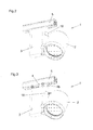
Figures 2 to 5 are views showing a sequence of the operation of the projector device suspended from a rail installed on the ceiling. - An embodiment of the
projector device 1 of this invention is shown in the figures. Thedevice 1 basically includes alight projector 2, acasing 3 and anadapter 4. - The
projector 2 is attached to thecasing 3 by means of an articulation that allows for convenient positioning. In its interior, thecasing 3 houses the electronic equipment of the projector device 1 (not shown). Thedevice 1 also includes anadapter 4 that is used to mount theprojector 2 and thecasing 3 in a three-phase rail 5 made in aluminium (seefigures 2 to 5 ) that is attached to a ceiling. The rail has a U-shaped cross section, with a grooved interior profile. - The
adapter 4 includes atop part 4a, that is inserted in therail 5 and is removable, so that theadapter 4 can be fixed along therail 5 and locked at the desired position. The adaptertop area 4a includes some electric contacts that, in operation, are inside therail 5 and allow for the electrical contact between thedevice 1 and therail 5 independent of the relative position of both elements. Aside lid 4c conceals and protects the interior of thetop area 4a of theadapter 4. - The
adapter 4 also includes alower part 4b, that is coupled to the rest of theprojector device 1, as further described hereinafter. Theadapter 4 and therail 5 constitute standard elements for one skilled in the art, for this reason the operation and structure of the same will not be further explained. - The
projector device 1 of this invention includes a mechanism ofautomatic actuation 6 that allows for the longitudinal movement of saidadapter 4 in relation to saidcasing 3 between the mounted position and removal position of saiddevice 1. - In this description, mounted position means a position where the
top part 4b of theadapter 4 is housed in the interior of thecasing 3, so that theadapter 4 is totally concealed when thedevice 1 is mounted in therail 5 and in operation (figure 2 ). Removal position means a position where thelower part 4b of theadapter 4 is located outside thecasing 3 and is visible, allowing for mounting and removing thedevice 1 from the rail 5 (figures 3 to 5 ). - Next, the structure and the actuation of the mechanism of
automatic actuation 6 of the device according to theinvention 1 will be described. - With reference again to
Figure 1 , aconnection washer 7 and anejection bush 8 are joined by means of arivet 9, with a washer between the same, that allows the connection washer 7 to rotate 180 degrees in relation to thebush 8. A guidingtop lid 10 that covers thecasing 3 is held between theconnection washer 7 and thebush 8. - The
connection washer 7 is attached to thelower part 4b of theadapter 4, that rotates 180 degrees solidarily with said connection washer 7. Anejection shaft 11 is attached by means of twoscrews 12 to theejection bush 8. - A
spring 13 is arranged by surrounding the lower end of theshaft 11, between twolongitudinal ribs 14 of theshaft 11 and alower cover 15. Saidspring 13 tends to separate the group composed of theconnection washer 7, theejection bush 8, therivet 9 and theshaft 11 in relation to thelower cover 15. - A
locking piece 16 is mounted between thelower cover 15 and theshaft 11, by surrounding theribs 14. Saidlocking piece 16 includes two columns each one being associated to itsspring 17 and is attached to apush button 18 at its opposite end by means of a screw. Thelocking piece 16 and thespring 17 are mounted inside thecover 15, with capacity of lateral movement in relation to the same. Thelocking piece 16 tends to be laterally ejected thanks to the action of saidsprings 17. - The
cover 15 is screwed to thelid 10 by means of twoscrews 19, so that the group of elements described is encapsulated. Thelid 10, in turn, is attached to thecasing 3 by means of twoscrews 20 that are screwed in somesupports 21, completely closing the housing of thecasing 3 that contains the transformer and the electrical wiring (not shown). Thesupports 21 are situated slightly under the top edge of thecasing 3, so that thelid 10 and the top walls of thecasing 3 conform another top accommodation for thelower part 4b of theadapter 4. - The power supply wires that transport the electric power from the rail 5 (not shown) pass across the interior of the connection washer 7, the
ejection bush 8, therivet 9 and theshaft 11 to the interior of thecasing 3. - In this way, the mechanism of
automatic actuation 6 is integrated in theprojector device 1. - The operation of the mechanism of
automatic actuation 6 of the device according to theinvention 1 is explained infigures 2 to 5 . - The device according to the
invention 1 attached to therail 5 in a mounted position is shown inFigure 2 . As can be seen, theadapter 4 is completely concealed, with its top 4a inserted in therail 5 and itslower part 4b housed in the top of thecasing 3. In this position, the lockingpiece 16 is located on the top edge of thelongitudinal ribs 14 of theshaft 11, thesprings 17 tend to move thepiece 16 laterally towards the exterior, so that the top edge of theribs 14 abuts against thenarrowest part 16b of thepiece 16. This makes theshaft 11 longitudinally held by the lockingpiece 16 and kept in the position closer to thecover 15, with thespring 13 in a condition of maximum compression. - ***When a user wants to remove the
device 1 from therail 5 or to carry out any other operation, he/she pushes the push button 18 (figure 3 ). When pushing thepush button 18, the same laterally moves the lockingpiece 16 in the direction opposite to the force which is exerted by thesprings 17. This makes thenarrowest part 16b of thepiece 16 also move laterally, so that theribs 14 of theshaft 11 can pass through awider part 16a of thepiece 16, and theshaft 11 can move longitudinally in relation to saidpiece 16. In this way, thecover 15 and thepiece 16 move down thanks to the action of thespring 13. Accordingly, when the user pushes thepush button 18, the group made by thecasing 3 and theprojector 2 of thedevice 1 moves down automatically in relation to theadapter 4, by letting thelower part 4b of the same, that was housed in the top of thecasing 3 in the mounted position, become exposed. - As shows in
Figure 4 , in the removal position, thecasing 3 can rotate 180 degrees relative to the adapter 4 (90 degrees in one direction or in the opposite direction) so as to provide access to the fastening means of theadapter 4 to therail 5 and other elements of the adapter 4 (not shown in detail). In this way, by operating afastening lever 22, theadapter 4 can be released from therail 5, and theprojector device 1 can easily be removed or situated in another location along the rail 5 (figure 5 ). - In order to reinstall the
device 1 to therail 5, the process disclosed is repeated in reverse. Once theadapter 4 is coupled to therail 5, thecasing 3 is rotated 90 degrees, in order to align with theadapter 4, and pushed upwards, by moving also thecover 15 and thelocking piece 16 upwards, and by compressing thespring 13. When the lockingpiece 16 is located on the top edge of theribs 14 of theshaft 11, said lockingpiece 16, along with thepush button 18, is moved again laterally towards the exterior thanks to the action of thesprings 17, till itsnarrowest part 16b locks theribs 14 of theshaft 11 again, keeping theprojector device 1 in the mounted position. - As can be seen, the
device 1 of the invention can be removed from therail 5 quickly and easily. It is necessary just to push thepush button 18 so that thecasing 3 is moved automatically downwards, leaving thelower part 4b of theadapter 4 exposed. Thanks to the mechanism ofautomatic actuation 6 of theprojector device 1 of this invention, the drawbacks of the prior art devices are overcome. It is no longer necessary for the user to pull thecasing 3 down against the elastic force of a spring to put thedevice 1 in its removal position, avoiding in this way the discomfort that it involves and the risk of therail 5 detaching from the ceiling. - Although in this description, reference has been made to a specific embodiment of the device according to the
invention 1, other configurations within the scope of the invention defined in the following claims are possible. For example, a lever or other similar device could be used instead of apush button 18 for the actuation of thespring 13 from the mounted position to the removal position. Likewise, thepush button 18 could be situated in another location of thecasing 3 for easier access, or even on another piece of thedevice 1.
Claims (7)
- Suspended projector device (1) including a projector (2), a casing (3) that houses electronic equipment in its interior, and an adapter (4) that has a top area (4a) of connection for its insertion inside a rail (5) which allows for the projector sliding along said rail, and a lower area (4b) attached to the projector device (1), so that, in operation, the projector device (1) is suspended from the rail (5) by means of said adapter (4) and can be arranged along it, said adapter (4) being completely concealed in its mounted position, where its lower area (4b) is housed in said casing (3), and said adapter (4) being able to be moved longitudinally in relation to said casing (3) between said mounted position and a removal position, where the lower area (4b) of the adapter (4) is not housed in the casing (3), characterized in that it includes automatic actuation means (6) for the longitudinal movement of said adapter (4) in relation to said casing (3) from the mounted position to the removal position.
- Device (1), according to claim 1, characterized in that the automatic actuation means (6) include elastic means (13) that tend to move said adapter (4) away in relation to said casing (3) and actuation means (18) of said elastic means (13) to move the adapter from the mounted position to the removal position.
- Device (1), according to claim 2, characterized in that the elastic means include a compression spring (13) associated to the lower area (4b) of the adapter at one end and associated to the casing (3) at the other end.
- Device (1), according to claim 2 or 3, characterized in that the actuation means of said elastic means (13) include a push button (18).
- Device (1), according to claim 4, characterized in that the push button (18) is situated in the casing (3).
- Device (1), according to claim 4 or 5, characterized in that the push button (18) is associated to a locking piece (16) that includes two positions, a first position that corresponds to the mounted position of the device (1), and a second position that corresponds to the removal position of the device (1).
- Device (1), according to claim 6, characterized in that, in the first position, the locking piece (16) is attached to a piece (11) associated to the lower part (4b) of the adapter (4) by locking the longitudinal movement between the casing (3) and the adapter (4) and by keeping the spring (13) compressed and, in the second position, the locking piece (16) is released from the piece (11) associated to the lower part (4b) of the adapter (4) allowing for the longitudinal movement between the casing (3) and the adapter (4) and allowing for the spring (13) to extend by moving the casing (3) and the adapter (4) away.
Applications Claiming Priority (1)
| Application Number | Priority Date | Filing Date | Title |
|---|---|---|---|
| ES200701974U ES1066182Y (en) | 2007-09-28 | 2007-09-28 | SUSPENDED PROJECTOR DEVICE |
Publications (3)
| Publication Number | Publication Date |
|---|---|
| EP2042804A2 true EP2042804A2 (en) | 2009-04-01 |
| EP2042804A3 EP2042804A3 (en) | 2010-08-04 |
| EP2042804B1 EP2042804B1 (en) | 2011-09-14 |
Family
ID=38787346
Family Applications (1)
| Application Number | Title | Priority Date | Filing Date |
|---|---|---|---|
| EP08164682A Not-in-force EP2042804B1 (en) | 2007-09-28 | 2008-09-19 | Suspended projector |
Country Status (4)
| Country | Link |
|---|---|
| EP (1) | EP2042804B1 (en) |
| AT (1) | ATE524694T1 (en) |
| DK (1) | DK2042804T3 (en) |
| ES (2) | ES1066182Y (en) |
Cited By (3)
| Publication number | Priority date | Publication date | Assignee | Title |
|---|---|---|---|---|
| EP2672176A1 (en) | 2012-06-05 | 2013-12-11 | Antares Iluminación S.A. | Light projecting device |
| EP3091276A1 (en) * | 2015-04-13 | 2016-11-09 | Paulmann Licht GmbH | Lighting fixture to be mounted in a support, in particular in a relevant guide-holder |
| DE102019000410A1 (en) * | 2019-01-22 | 2020-07-23 | Paulmann Licht Gmbh | Luminaire and adapter for luminaire |
Family Cites Families (3)
| Publication number | Priority date | Publication date | Assignee | Title |
|---|---|---|---|---|
| US3529274A (en) * | 1968-01-04 | 1970-09-15 | Us Industries Inc | Power distribution system |
| US7160001B2 (en) * | 2003-10-14 | 2007-01-09 | Cooper Industries | Focus assembly for a track light |
| PT1956291E (en) * | 2006-02-16 | 2013-02-13 | Antares Iluminacion Sa | Suspended projector |
-
2007
- 2007-09-28 ES ES200701974U patent/ES1066182Y/en not_active Expired - Fee Related
-
2008
- 2008-09-19 AT AT08164682T patent/ATE524694T1/en active
- 2008-09-19 EP EP08164682A patent/EP2042804B1/en not_active Not-in-force
- 2008-09-19 DK DK08164682.0T patent/DK2042804T3/en active
- 2008-09-19 ES ES08164682T patent/ES2379195T3/en active Active
Cited By (5)
| Publication number | Priority date | Publication date | Assignee | Title |
|---|---|---|---|---|
| EP2672176A1 (en) | 2012-06-05 | 2013-12-11 | Antares Iluminación S.A. | Light projecting device |
| EP3091276A1 (en) * | 2015-04-13 | 2016-11-09 | Paulmann Licht GmbH | Lighting fixture to be mounted in a support, in particular in a relevant guide-holder |
| DE102019000410A1 (en) * | 2019-01-22 | 2020-07-23 | Paulmann Licht Gmbh | Luminaire and adapter for luminaire |
| EP3686488A1 (en) * | 2019-01-22 | 2020-07-29 | Paulmann Licht GmbH | Light and fastener for light |
| DE102019000410B4 (en) | 2019-01-22 | 2022-12-08 | Paulmann Licht Gmbh | Lamp and adapter for lamp |
Also Published As
| Publication number | Publication date |
|---|---|
| EP2042804A3 (en) | 2010-08-04 |
| EP2042804B1 (en) | 2011-09-14 |
| ATE524694T1 (en) | 2011-09-15 |
| DK2042804T3 (en) | 2011-12-19 |
| ES1066182U (en) | 2007-12-16 |
| ES2379195T3 (en) | 2012-04-23 |
| ES1066182Y (en) | 2008-03-16 |
Similar Documents
| Publication | Publication Date | Title |
|---|---|---|
| US8251566B1 (en) | Push button release for luminaires in a track lighting system | |
| KR102044663B1 (en) | LED lighting for rail system | |
| US7559782B2 (en) | Storage device box | |
| CN110842496B (en) | Mounting device | |
| US8472200B2 (en) | Locking mechanism for a housing to hold a plug-in module | |
| EP2042804B1 (en) | Suspended projector | |
| EP0243436A1 (en) | Equipment enclosure | |
| EP2026544A1 (en) | A mobile phone holder for mechanical vehicles | |
| CN102273033A (en) | Motor control center subunit having visible contact disconnection and method of manufacture | |
| EP3614040B1 (en) | A light source plate and a ceiling light | |
| US9831645B2 (en) | Spring loaded, bistable connect/disconnect for MCC unit | |
| CN102762811A (en) | Synchronization device for synchronizing two actuating drives for moving a movable furniture part | |
| US9025320B2 (en) | Housing for computer system as well as computer system with such a housing | |
| CN113067293A (en) | Electrical junction box | |
| EP1956291B1 (en) | Suspended projector | |
| CN106715197B (en) | Adjustment devices, exterior mirror units, motor vehicles | |
| CN1794940A (en) | Household appliance with two mutually hinged heating sub-assemblies | |
| US10483063B1 (en) | Protective relay with easy withdrawal | |
| EP3617605B1 (en) | Air conditioner | |
| CN213877988U (en) | Manual operation mechanism and molded case circuit breaker | |
| US20110073450A1 (en) | Wall mounted switch extender | |
| WO2014192524A1 (en) | Case unit | |
| US6072132A (en) | Apparatus for mounting a motor operator on a circuit | |
| EP1248338A1 (en) | Reset switch | |
| KR102121657B1 (en) | Lighting fitting device |
Legal Events
| Date | Code | Title | Description |
|---|---|---|---|
| PUAI | Public reference made under article 153(3) epc to a published international application that has entered the european phase |
Free format text: ORIGINAL CODE: 0009012 |
|
| 17P | Request for examination filed |
Effective date: 20080919 |
|
| AK | Designated contracting states |
Kind code of ref document: A2 Designated state(s): AT BE BG CH CY CZ DE DK EE ES FI FR GB GR HR HU IE IS IT LI LT LU LV MC MT NL NO PL PT RO SE SI SK TR |
|
| AX | Request for extension of the european patent |
Extension state: AL BA MK RS |
|
| PUAL | Search report despatched |
Free format text: ORIGINAL CODE: 0009013 |
|
| AK | Designated contracting states |
Kind code of ref document: A3 Designated state(s): AT BE BG CH CY CZ DE DK EE ES FI FR GB GR HR HU IE IS IT LI LT LU LV MC MT NL NO PL PT RO SE SI SK TR |
|
| AX | Request for extension of the european patent |
Extension state: AL BA MK RS |
|
| GRAP | Despatch of communication of intention to grant a patent |
Free format text: ORIGINAL CODE: EPIDOSNIGR1 |
|
| RIC1 | Information provided on ipc code assigned before grant |
Ipc: F21V 21/34 20060101AFI20110201BHEP |
|
| AKX | Designation fees paid |
Designated state(s): AT BE BG CH CY CZ DE DK EE ES FI FR GB GR HR HU IE IS IT LI LT LU LV MC MT NL NO PL PT RO SE SI SK TR |
|
| GRAS | Grant fee paid |
Free format text: ORIGINAL CODE: EPIDOSNIGR3 |
|
| GRAA | (expected) grant |
Free format text: ORIGINAL CODE: 0009210 |
|
| RAP1 | Party data changed (applicant data changed or rights of an application transferred) |
Owner name: ANTARES ILUMINACION, S.A. |
|
| AK | Designated contracting states |
Kind code of ref document: B1 Designated state(s): AT BE BG CH CY CZ DE DK EE ES FI FR GB GR HR HU IE IS IT LI LT LU LV MC MT NL NO PL PT RO SE SI SK TR |
|
| REG | Reference to a national code |
Ref country code: GB Ref legal event code: FG4D |
|
| REG | Reference to a national code |
Ref country code: CH Ref legal event code: EP |
|
| REG | Reference to a national code |
Ref country code: IE Ref legal event code: FG4D |
|
| REG | Reference to a national code |
Ref country code: DE Ref legal event code: R096 Ref document number: 602008009738 Country of ref document: DE Effective date: 20111110 |
|
| REG | Reference to a national code |
Ref country code: CH Ref legal event code: NV Representative=s name: SEDIN SA |
|
| REG | Reference to a national code |
Ref country code: NL Ref legal event code: T3 |
|
| REG | Reference to a national code |
Ref country code: DK Ref legal event code: T3 |
|
| PG25 | Lapsed in a contracting state [announced via postgrant information from national office to epo] |
Ref country code: NO Free format text: LAPSE BECAUSE OF FAILURE TO SUBMIT A TRANSLATION OF THE DESCRIPTION OR TO PAY THE FEE WITHIN THE PRESCRIBED TIME-LIMIT Effective date: 20111214 Ref country code: FI Free format text: LAPSE BECAUSE OF FAILURE TO SUBMIT A TRANSLATION OF THE DESCRIPTION OR TO PAY THE FEE WITHIN THE PRESCRIBED TIME-LIMIT Effective date: 20110914 Ref country code: HR Free format text: LAPSE BECAUSE OF FAILURE TO SUBMIT A TRANSLATION OF THE DESCRIPTION OR TO PAY THE FEE WITHIN THE PRESCRIBED TIME-LIMIT Effective date: 20110914 Ref country code: LT Free format text: LAPSE BECAUSE OF FAILURE TO SUBMIT A TRANSLATION OF THE DESCRIPTION OR TO PAY THE FEE WITHIN THE PRESCRIBED TIME-LIMIT Effective date: 20110914 Ref country code: SE Free format text: LAPSE BECAUSE OF FAILURE TO SUBMIT A TRANSLATION OF THE DESCRIPTION OR TO PAY THE FEE WITHIN THE PRESCRIBED TIME-LIMIT Effective date: 20110914 |
|
| LTIE | Lt: invalidation of european patent or patent extension |
Effective date: 20110914 |
|
| PG25 | Lapsed in a contracting state [announced via postgrant information from national office to epo] |
Ref country code: CY Free format text: LAPSE BECAUSE OF FAILURE TO SUBMIT A TRANSLATION OF THE DESCRIPTION OR TO PAY THE FEE WITHIN THE PRESCRIBED TIME-LIMIT Effective date: 20110914 Ref country code: LV Free format text: LAPSE BECAUSE OF FAILURE TO SUBMIT A TRANSLATION OF THE DESCRIPTION OR TO PAY THE FEE WITHIN THE PRESCRIBED TIME-LIMIT Effective date: 20110914 Ref country code: GR Free format text: LAPSE BECAUSE OF FAILURE TO SUBMIT A TRANSLATION OF THE DESCRIPTION OR TO PAY THE FEE WITHIN THE PRESCRIBED TIME-LIMIT Effective date: 20111215 Ref country code: SI Free format text: LAPSE BECAUSE OF FAILURE TO SUBMIT A TRANSLATION OF THE DESCRIPTION OR TO PAY THE FEE WITHIN THE PRESCRIBED TIME-LIMIT Effective date: 20110914 |
|
| REG | Reference to a national code |
Ref country code: ES Ref legal event code: FG2A Ref document number: 2379195 Country of ref document: ES Kind code of ref document: T3 Effective date: 20120423 |
|
| PG25 | Lapsed in a contracting state [announced via postgrant information from national office to epo] |
Ref country code: MC Free format text: LAPSE BECAUSE OF NON-PAYMENT OF DUE FEES Effective date: 20110930 Ref country code: IS Free format text: LAPSE BECAUSE OF FAILURE TO SUBMIT A TRANSLATION OF THE DESCRIPTION OR TO PAY THE FEE WITHIN THE PRESCRIBED TIME-LIMIT Effective date: 20120114 Ref country code: CZ Free format text: LAPSE BECAUSE OF FAILURE TO SUBMIT A TRANSLATION OF THE DESCRIPTION OR TO PAY THE FEE WITHIN THE PRESCRIBED TIME-LIMIT Effective date: 20110914 Ref country code: SK Free format text: LAPSE BECAUSE OF FAILURE TO SUBMIT A TRANSLATION OF THE DESCRIPTION OR TO PAY THE FEE WITHIN THE PRESCRIBED TIME-LIMIT Effective date: 20110914 |
|
| PG25 | Lapsed in a contracting state [announced via postgrant information from national office to epo] |
Ref country code: EE Free format text: LAPSE BECAUSE OF FAILURE TO SUBMIT A TRANSLATION OF THE DESCRIPTION OR TO PAY THE FEE WITHIN THE PRESCRIBED TIME-LIMIT Effective date: 20110914 Ref country code: PT Free format text: LAPSE BECAUSE OF FAILURE TO SUBMIT A TRANSLATION OF THE DESCRIPTION OR TO PAY THE FEE WITHIN THE PRESCRIBED TIME-LIMIT Effective date: 20120116 Ref country code: PL Free format text: LAPSE BECAUSE OF FAILURE TO SUBMIT A TRANSLATION OF THE DESCRIPTION OR TO PAY THE FEE WITHIN THE PRESCRIBED TIME-LIMIT Effective date: 20110914 Ref country code: RO Free format text: LAPSE BECAUSE OF FAILURE TO SUBMIT A TRANSLATION OF THE DESCRIPTION OR TO PAY THE FEE WITHIN THE PRESCRIBED TIME-LIMIT Effective date: 20110914 |
|
| REG | Reference to a national code |
Ref country code: IE Ref legal event code: MM4A |
|
| PLBE | No opposition filed within time limit |
Free format text: ORIGINAL CODE: 0009261 |
|
| STAA | Information on the status of an ep patent application or granted ep patent |
Free format text: STATUS: NO OPPOSITION FILED WITHIN TIME LIMIT |
|
| PG25 | Lapsed in a contracting state [announced via postgrant information from national office to epo] |
Ref country code: IE Free format text: LAPSE BECAUSE OF NON-PAYMENT OF DUE FEES Effective date: 20110919 |
|
| 26N | No opposition filed |
Effective date: 20120615 |
|
| REG | Reference to a national code |
Ref country code: DE Ref legal event code: R097 Ref document number: 602008009738 Country of ref document: DE Effective date: 20120615 |
|
| PG25 | Lapsed in a contracting state [announced via postgrant information from national office to epo] |
Ref country code: MT Free format text: LAPSE BECAUSE OF FAILURE TO SUBMIT A TRANSLATION OF THE DESCRIPTION OR TO PAY THE FEE WITHIN THE PRESCRIBED TIME-LIMIT Effective date: 20110914 |
|
| REG | Reference to a national code |
Ref country code: DE Ref legal event code: R082 Ref document number: 602008009738 Country of ref document: DE Representative=s name: PRINZ & PARTNER MBB PATENTANWAELTE RECHTSANWAE, DE |
|
| REG | Reference to a national code |
Ref country code: CH Ref legal event code: NV Representative=s name: ING. MARCO ZARDI C/O M. ZARDI AND CO. S.A., CH |
|
| PG25 | Lapsed in a contracting state [announced via postgrant information from national office to epo] |
Ref country code: LU Free format text: LAPSE BECAUSE OF NON-PAYMENT OF DUE FEES Effective date: 20110919 |
|
| PG25 | Lapsed in a contracting state [announced via postgrant information from national office to epo] |
Ref country code: BG Free format text: LAPSE BECAUSE OF FAILURE TO SUBMIT A TRANSLATION OF THE DESCRIPTION OR TO PAY THE FEE WITHIN THE PRESCRIBED TIME-LIMIT Effective date: 20111214 |
|
| PG25 | Lapsed in a contracting state [announced via postgrant information from national office to epo] |
Ref country code: TR Free format text: LAPSE BECAUSE OF FAILURE TO SUBMIT A TRANSLATION OF THE DESCRIPTION OR TO PAY THE FEE WITHIN THE PRESCRIBED TIME-LIMIT Effective date: 20110914 |
|
| PG25 | Lapsed in a contracting state [announced via postgrant information from national office to epo] |
Ref country code: HU Free format text: LAPSE BECAUSE OF FAILURE TO SUBMIT A TRANSLATION OF THE DESCRIPTION OR TO PAY THE FEE WITHIN THE PRESCRIBED TIME-LIMIT Effective date: 20110914 |
|
| REG | Reference to a national code |
Ref country code: FR Ref legal event code: PLFP Year of fee payment: 8 |
|
| REG | Reference to a national code |
Ref country code: FR Ref legal event code: PLFP Year of fee payment: 9 |
|
| REG | Reference to a national code |
Ref country code: FR Ref legal event code: PLFP Year of fee payment: 10 |
|
| PGFP | Annual fee paid to national office [announced via postgrant information from national office to epo] |
Ref country code: CH Payment date: 20170927 Year of fee payment: 10 Ref country code: GB Payment date: 20170927 Year of fee payment: 10 Ref country code: FR Payment date: 20170925 Year of fee payment: 10 Ref country code: IT Payment date: 20170925 Year of fee payment: 10 |
|
| PGFP | Annual fee paid to national office [announced via postgrant information from national office to epo] |
Ref country code: DK Payment date: 20170925 Year of fee payment: 10 Ref country code: BE Payment date: 20170927 Year of fee payment: 10 Ref country code: AT Payment date: 20170920 Year of fee payment: 10 Ref country code: NL Payment date: 20170926 Year of fee payment: 10 |
|
| PGFP | Annual fee paid to national office [announced via postgrant information from national office to epo] |
Ref country code: DE Payment date: 20170927 Year of fee payment: 10 |
|
| PGFP | Annual fee paid to national office [announced via postgrant information from national office to epo] |
Ref country code: ES Payment date: 20171006 Year of fee payment: 10 |
|
| REG | Reference to a national code |
Ref country code: DE Ref legal event code: R119 Ref document number: 602008009738 Country of ref document: DE |
|
| REG | Reference to a national code |
Ref country code: CH Ref legal event code: PL |
|
| REG | Reference to a national code |
Ref country code: DK Ref legal event code: EBP Effective date: 20180930 |
|
| REG | Reference to a national code |
Ref country code: NL Ref legal event code: MM Effective date: 20181001 |
|
| REG | Reference to a national code |
Ref country code: AT Ref legal event code: MM01 Ref document number: 524694 Country of ref document: AT Kind code of ref document: T Effective date: 20180919 |
|
| GBPC | Gb: european patent ceased through non-payment of renewal fee |
Effective date: 20180919 |
|
| REG | Reference to a national code |
Ref country code: BE Ref legal event code: MM Effective date: 20180930 |
|
| PG25 | Lapsed in a contracting state [announced via postgrant information from national office to epo] |
Ref country code: NL Free format text: LAPSE BECAUSE OF NON-PAYMENT OF DUE FEES Effective date: 20181001 |
|
| PG25 | Lapsed in a contracting state [announced via postgrant information from national office to epo] |
Ref country code: DE Free format text: LAPSE BECAUSE OF NON-PAYMENT OF DUE FEES Effective date: 20190402 Ref country code: IT Free format text: LAPSE BECAUSE OF NON-PAYMENT OF DUE FEES Effective date: 20180919 |
|
| PG25 | Lapsed in a contracting state [announced via postgrant information from national office to epo] |
Ref country code: BE Free format text: LAPSE BECAUSE OF NON-PAYMENT OF DUE FEES Effective date: 20180930 Ref country code: CH Free format text: LAPSE BECAUSE OF NON-PAYMENT OF DUE FEES Effective date: 20180930 Ref country code: FR Free format text: LAPSE BECAUSE OF NON-PAYMENT OF DUE FEES Effective date: 20180930 Ref country code: LI Free format text: LAPSE BECAUSE OF NON-PAYMENT OF DUE FEES Effective date: 20180930 |
|
| PG25 | Lapsed in a contracting state [announced via postgrant information from national office to epo] |
Ref country code: GB Free format text: LAPSE BECAUSE OF NON-PAYMENT OF DUE FEES Effective date: 20180919 Ref country code: AT Free format text: LAPSE BECAUSE OF NON-PAYMENT OF DUE FEES Effective date: 20180919 Ref country code: DK Free format text: LAPSE BECAUSE OF NON-PAYMENT OF DUE FEES Effective date: 20180930 |
|
| REG | Reference to a national code |
Ref country code: ES Ref legal event code: FD2A Effective date: 20191104 |
|
| PG25 | Lapsed in a contracting state [announced via postgrant information from national office to epo] |
Ref country code: ES Free format text: LAPSE BECAUSE OF NON-PAYMENT OF DUE FEES Effective date: 20180920 |