EP2042703A2 - Air-cooled engine - Google Patents
Air-cooled engine Download PDFInfo
- Publication number
- EP2042703A2 EP2042703A2 EP08021097A EP08021097A EP2042703A2 EP 2042703 A2 EP2042703 A2 EP 2042703A2 EP 08021097 A EP08021097 A EP 08021097A EP 08021097 A EP08021097 A EP 08021097A EP 2042703 A2 EP2042703 A2 EP 2042703A2
- Authority
- EP
- European Patent Office
- Prior art keywords
- cooling
- cylinder
- air
- fins
- base
- Prior art date
- Legal status (The legal status is an assumption and is not a legal conclusion. Google has not performed a legal analysis and makes no representation as to the accuracy of the status listed.)
- Granted
Links
- 238000001816 cooling Methods 0.000 claims abstract description 258
- 238000007664 blowing Methods 0.000 claims description 3
- 230000013011 mating Effects 0.000 claims description 3
- 238000004891 communication Methods 0.000 abstract description 4
- 229910052751 metal Inorganic materials 0.000 description 38
- 239000002184 metal Substances 0.000 description 38
- 238000005266 casting Methods 0.000 description 25
- 238000002485 combustion reaction Methods 0.000 description 23
- 230000005540 biological transmission Effects 0.000 description 18
- 239000007858 starting material Substances 0.000 description 14
- 238000004512 die casting Methods 0.000 description 13
- 230000000694 effects Effects 0.000 description 9
- 238000000034 method Methods 0.000 description 9
- 230000002093 peripheral effect Effects 0.000 description 8
- 229910000838 Al alloy Inorganic materials 0.000 description 6
- 238000010586 diagram Methods 0.000 description 6
- 238000003780 insertion Methods 0.000 description 6
- 230000037431 insertion Effects 0.000 description 6
- 229910052782 aluminium Inorganic materials 0.000 description 1
- XAGFODPZIPBFFR-UHFFFAOYSA-N aluminium Chemical compound [Al] XAGFODPZIPBFFR-UHFFFAOYSA-N 0.000 description 1
- 230000009286 beneficial effect Effects 0.000 description 1
- 230000015572 biosynthetic process Effects 0.000 description 1
- 230000002349 favourable effect Effects 0.000 description 1
- 239000002828 fuel tank Substances 0.000 description 1
- ZZUFCTLCJUWOSV-UHFFFAOYSA-N furosemide Chemical compound C1=C(Cl)C(S(=O)(=O)N)=CC(C(O)=O)=C1NCC1=CC=CO1 ZZUFCTLCJUWOSV-UHFFFAOYSA-N 0.000 description 1
- 239000010687 lubricating oil Substances 0.000 description 1
- 238000004519 manufacturing process Methods 0.000 description 1
- 239000000463 material Substances 0.000 description 1
- 239000003921 oil Substances 0.000 description 1
- 238000007789 sealing Methods 0.000 description 1
- 238000007493 shaping process Methods 0.000 description 1
- 238000007711 solidification Methods 0.000 description 1
- 230000008023 solidification Effects 0.000 description 1
Images









Classifications
-
- F—MECHANICAL ENGINEERING; LIGHTING; HEATING; WEAPONS; BLASTING
- F02—COMBUSTION ENGINES; HOT-GAS OR COMBUSTION-PRODUCT ENGINE PLANTS
- F02F—CYLINDERS, PISTONS OR CASINGS, FOR COMBUSTION ENGINES; ARRANGEMENTS OF SEALINGS IN COMBUSTION ENGINES
- F02F1/00—Cylinders; Cylinder heads
- F02F1/24—Cylinder heads
- F02F1/26—Cylinder heads having cooling means
- F02F1/28—Cylinder heads having cooling means for air cooling
- F02F1/30—Finned cylinder heads
- F02F1/32—Finned cylinder heads the cylinder heads being of overhead valve type
-
- F—MECHANICAL ENGINEERING; LIGHTING; HEATING; WEAPONS; BLASTING
- F01—MACHINES OR ENGINES IN GENERAL; ENGINE PLANTS IN GENERAL; STEAM ENGINES
- F01L—CYCLICALLY OPERATING VALVES FOR MACHINES OR ENGINES
- F01L1/00—Valve-gear or valve arrangements, e.g. lift-valve gear
- F01L1/02—Valve drive
- F01L1/024—Belt drive
-
- F—MECHANICAL ENGINEERING; LIGHTING; HEATING; WEAPONS; BLASTING
- F01—MACHINES OR ENGINES IN GENERAL; ENGINE PLANTS IN GENERAL; STEAM ENGINES
- F01P—COOLING OF MACHINES OR ENGINES IN GENERAL; COOLING OF INTERNAL-COMBUSTION ENGINES
- F01P1/00—Air cooling
- F01P1/02—Arrangements for cooling cylinders or cylinder heads, e.g. ducting cooling-air from its pressure source to cylinders or along cylinders
-
- F—MECHANICAL ENGINEERING; LIGHTING; HEATING; WEAPONS; BLASTING
- F02—COMBUSTION ENGINES; HOT-GAS OR COMBUSTION-PRODUCT ENGINE PLANTS
- F02F—CYLINDERS, PISTONS OR CASINGS, FOR COMBUSTION ENGINES; ARRANGEMENTS OF SEALINGS IN COMBUSTION ENGINES
- F02F1/00—Cylinders; Cylinder heads
- F02F1/24—Cylinder heads
-
- F—MECHANICAL ENGINEERING; LIGHTING; HEATING; WEAPONS; BLASTING
- F01—MACHINES OR ENGINES IN GENERAL; ENGINE PLANTS IN GENERAL; STEAM ENGINES
- F01P—COOLING OF MACHINES OR ENGINES IN GENERAL; COOLING OF INTERNAL-COMBUSTION ENGINES
- F01P1/00—Air cooling
- F01P1/02—Arrangements for cooling cylinders or cylinder heads, e.g. ducting cooling-air from its pressure source to cylinders or along cylinders
- F01P2001/023—Cooling cylinders
-
- F—MECHANICAL ENGINEERING; LIGHTING; HEATING; WEAPONS; BLASTING
- F01—MACHINES OR ENGINES IN GENERAL; ENGINE PLANTS IN GENERAL; STEAM ENGINES
- F01P—COOLING OF MACHINES OR ENGINES IN GENERAL; COOLING OF INTERNAL-COMBUSTION ENGINES
- F01P1/00—Air cooling
- F01P1/02—Arrangements for cooling cylinders or cylinder heads, e.g. ducting cooling-air from its pressure source to cylinders or along cylinders
- F01P2001/026—Cooling cylinder heads
-
- F—MECHANICAL ENGINEERING; LIGHTING; HEATING; WEAPONS; BLASTING
- F01—MACHINES OR ENGINES IN GENERAL; ENGINE PLANTS IN GENERAL; STEAM ENGINES
- F01P—COOLING OF MACHINES OR ENGINES IN GENERAL; COOLING OF INTERNAL-COMBUSTION ENGINES
- F01P5/00—Pumping cooling-air or liquid coolants
- F01P5/02—Pumping cooling-air; Arrangements of cooling-air pumps, e.g. fans or blowers
Definitions
- the present invention relates to an air-cooled engine that is cooled by cooling air.
- Air-cooled engines are forcefully cooled by cooling air sent to a cylinder head and a cylinder block from a cooling fan that is driven by a crankshaft. This type of air-cooled engine is disclosed in Japanese Laid-Open Patent Application No. 2-275021 and Japanese Examined Utility Model Application No. 58-19293 .
- an intake valve and an exhaust valve are opened and closed as a result of a camshaft being rotated by a crankshaft via a power transmission mechanism.
- the combustion chamber in the cylinder head and the cylinder in the cylinder block are cooled by cooling air sent from the cooling fan to the cylinder head and the cylinder block.
- the cooling air be conducted to the vicinity of the combustion chamber and the cylinder.
- the power transmission mechanism is disposed on the side of the cylinder head and on the side of the cylinder block. Therefore, a compartment for accommodating the power transmission mechanism is disposed in the vicinity of the combustion chamber and the cylinder. This compartment is an obstacle to the cooling air being conducted to the vicinity of the combustion chamber and the cylinder.
- the need has also increased for techniques whereby cooling air can be more actively conducted to the vicinity of the combustion chamber and the cylinder to further improve the effects of cooling the combustion chamber and the cylinder.
- the air-cooled engine disclosed in Japanese Examined Utility Model Application No. 58-19293 is an inclined-cylinder engine having a base on the bottom of the crank case, and also having a cylinder block and cylinder inclined to the side of the crank case.
- the air-cooled engine can be mounted on any other arbitrary member by using bolts inserted through mounting holes in the base.
- the outer periphery of the cylinder block has a plurality of cooling fins extending in a direction perpendicular to the axial line of the cylinder.
- the cylinder can be cooled by the flow of cooling air among the plurality of cooling fins.
- the casing for the air-cooled engine is often a cast article wherein the crank case, the base, and the cylinder block are integrated in order to reduce manufacturing costs.
- the metal mold is opened along the cooling fins after the molten metal in the cavity of the metal mold has solidified.
- the direction in which the metal mold opens is different from the orientation of the mounting holes of the base.
- the mounting holes cannot be formed simultaneously. After the casing is cast, the mounting holes must be mechanically worked in. This places a limit on improving the productivity of the casing.
- One method for solving these problems is to provide the metal mold with a separate sliding die, and to form mounting holes by using this sliding die. This method allows the mounting holes to be formed at the same time as the casing is being cast.
- the structure of the metal mold becomes complicated with this method because a sliding die is provided to the metal mold.
- the first embodiment of the present invention provides an air-cooled engine that is cooled by cooling air, comprising a cylinder block that comprises a cylinder having a reciprocating piston, and a cylinder head provided to a distal end of the cylinder block; wherein the cylinder block comprises at least one cylinder-cooling through-duct capable of transmitting the cooling air, on the periphery of the cylinder; the cylinder head comprises at least one head-cooling through-duct capable of transmitting the cooling air; and the cylinder-cooling ducts and the head-cooling duct extend in a direction perpendicular to the axial line of the cylinder, and are communicated with each other by means of at least one communicating channel formed on the cylinder block and the cylinder head.
- the cylinder-cooling ducts can pass through the vicinity of the cylinder, and the head-cooling duct can pass through the vicinity of the combustion chamber even in an air-cooled engine in which the power transmission mechanism for transmitting the power of the crankshaft to the camshaft, and the compartment for accommodating the power transmission mechanism, are disposed on the side of the cylinder head and on the side of the cylinder block.
- the cooling air can then be conducted to the vicinity of the combustion chamber and the cylinder by being admitted into the cylinder-cooling ducts and the head-cooling duct. Therefore, the combustion chamber and the cylinder can be cooled even more efficiently.
- the cylinder-cooling ducts and the cooling duct are communicated using communication channels, part of the cooling air flowing through the head-cooling duct can be admitted into the cylinder-cooling ducts and used as cooling air for the cylinder. Therefore, the cooling air needed to cool the cylinder can be adequately conducted to the cylinder. As a result, the cylinder cooling effect can be further improved.
- the cylinder-cooling ducts be composed of a plurality of ducts, and that the one cylinder-cooling duct from among this plurality of cylinder-cooling ducts that is adjacent to the head-cooling duct be communicated with the head-cooling duct via the communicating channels. Therefore, cooling air can be passed through the plurality of cylinder-cooling ducts, and the vicinity of the cylinder can be cooled. Moreover, a greater amount of cooling air can be admitted into the cylinder-cooling duct adjacent to the head-cooling duct, i.e., the cylinder-cooling duct nearest to the combustion chamber. Therefore, the effects of cooling can be further improved by conducting a greater amount of cooling air to the vicinity of the combustion chamber and the cylinder.
- the communication channels are preferably composed of a pair of separated communication channels. Therefore, part of the cooling air flowing through the head-cooling duct can be more adequately admitted into the cylinder-cooling ducts. As a result, the effects of cooling the cylinder can be further improved.
- the cylinder head have a valve chamber for accommodating a camshaft that operates an intake valve and an exhaust valve, and a guide-cooling duct communicated with the head-cooling duct; that the camshaft be driven by a crankshaft via a power transmission mechanism disposed along the cylinder; and that an inlet for the guide-cooling duct be formed in the cylinder head on the side opposite from the power transmission mechanism. Therefore, cooling air can be admitted into the head-cooling duct via the guide-cooling duct from the side opposite from the power transmission mechanism as well. Accordingly, the effects of cooling the combustion chamber and the cylinder can be further improved because a greater amount of cooling air can be made to flow into the head-cooling duct.
- an inlet for the guide-cooling duct is provided to the cylinder head on the side opposite from the power transmission mechanism, the inlet can easily be made to face outward. Accordingly, there is a greater degree of freedom when designing the position and shape of the guide-cooling duct.
- the second embodiment of the present invention provides an air-cooled engine that is cooled by cooling air, comprising a crank case for accommodating a crankshaft, a cylinder block that is formed integrally on the crank case and is provided a cylinder having a reciprocating piston, and a base that is integrally formed on the crank case and can be mounted on arbitrary mating member by a plurality of fastening members; wherein the base has a plurality of mounting holes through which the fastening members can be inserted; the cylinder block is disposed at an incline in relation to the base and has a plurality of cooling fins formed integrally in the shape of a loop so as to encircle the outer periphery; and the cooling fins have the base-side halves disposed closer to the base in relation to the axial line of the cylinder and formed so as to be parallel to the center line of the mounting holes.
- the metal mold can be opened along the base-side halves of the cooling fins, whereby the direction of opening the metal mold is aligned with the orientation of the mounting holes. Therefore, the mounting holes can be formed at the same time as the casing is being cast in the metal mold. Matching the opening direction of the metal mold with the orientation of the mounting holes in this manner makes it possible to shape the mounting holes at the same time that the casing is being cast in the metal mold. Moreover, there is no need to provide the metal mold with a sliding die for shaping the mounting holes, and the metal mold can be simplified.
- the cylinder block be disposed at a higher location than the base and be inclined upward in relation to the base; and that the engine also have a cooling fan for sending cooling air from the crank case to the base-side halves of the cooling fins. Therefore, the cooling air sent from the cooling fan can be more smoothly conducted to the cooling fins. Accordingly, the effects of cooling can be improved because the plurality of cooling fins and the cylinder block can be sufficiently cooled with cooling air. Furthermore, it is preferable that the cooling fan for blowing air has a plurality of blades, the plurality of blades have a bottommost blade, the bottommost blade has a distal end, and the distal end is disposed below the cooling fins.
- cooling fins have base-side halves, the base-side halves have top ends, and the top ends be positioned on the axial line of the cylinder.
- the air-cooled engine 10 comprises a cooling fan 13, a fan cover 15 that covers the cooling fan 13, a recoil starter 18, a starter cover 20 that covers the recoil starter 18, a fuel tank 22, an air cleaner 23, and a muffler 24.
- the cooling fan 13 and the recoil starter 18 are linked with a crankshaft 12 (see FIG. 3 ).
- the fan cover 15 has an opening 16 through which the recoil starter 18 passes.
- the air-cooled engine 10 is a so-called OHC (overhead-cam) single-cylinder engine having a tilted cylinder, wherein a single cylinder 26 and a cylinder block 33 are tilted upward at fixed angles in relation to a horizontal base 34 located at the bottom of a crank case 31.
- OHC overhead-cam
- the casing 25 of the air-cooled engine 10 is composed of a crank case 31, a case cover 32 that closes off the opening 31a of the crank case 31, a cylinder block 33 formed integrally on the side of the crank case 31 (the left end in FIG. 2 ), and a horizontal base 34 formed integrally on the bottom of the crank case 31.
- the crank case 31 has a crank chamber 31d (accommodating space 31d) that rotatably accommodates the crankshaft 12.
- the opening 31a of the crank case 31 can be covered with the case cover 32 by bolting the case cover 32 onto the crank case 31.
- the crankshaft 12 has a power output unit 12a used to output the generated power and located at the end that extends through and past the case cover 32.
- the cylinder block 33 and the cylinder 26 housed within the cylinder block 33 are tilted upward from the side portion of the crank case 31. Therefore, the cylinder 26 and the cylinder block 33 are disposed farther up than the base 34, and are tilted upward in relation to the base 34.
- the crank case 31 comprises three bosses 35 (only two are shown) on one side 31b, and one boss 41 disposed at a position separate from the three bosses 35, as shown in FIG. 2 .
- the three bosses 35 have the threaded parts 36a of stud bolts 36 screwed into screw holes 35a.
- the three stud bolts 36 are thus mounted on one side 31b of the crank case 31.
- the stud bolts 36 also have threaded parts 36b at their distal ends.
- the procedure of attaching the fan cover 15 and the starter cover 20 is as follows.
- the three threaded parts 36b are inserted into three mounting holes 38 in the fan cover 15.
- the position of a mounting hole 39 in the fan cover 15 is matched with a screw hole 41a in a boss 41.
- the three threaded parts 36b are inserted through the three mounting holes 43 (only two are shown) in the starter cover 20.
- a bolt 44 in the fan cover 15 is inserted into a mounting hole 45 in the starter cover 20.
- nuts 46 are screwed over the three threaded parts 36b and the bolt 44.
- a bolt 48 is inserted through the mounting hole 39 in the fan cover 15, and a threaded part 48a is screwed into the screw hole 41a in the boss 41.
- the fan cover 15 can thus be attached to one side 31b of the crank case 31, and the starter cover 20 can be attached to the fan cover 15.
- the recoil starter 18 includes a pulley 51 linked with the crankshaft 12 (see FIG. 3 ), and a starter rope 52 that is wound around the pulley 51.
- the starter rope 52 has a grip 53 at the distal end.
- FIG. 2 shows the grip 53 as being detached from the starter rope 52 and positioned on the side of the starter cover 20, for the sake of simplicity.
- the air-cooled engine 10 comprises a guide cover 21 that covers the tops of both the cylinder head 28 and the cylinder block 33.
- the guide cover 21 performs the function of guiding cooling air Wi from the cooling fan 13 along the top portion 33b of the cylinder block 33.
- the cover is bolted onto the cylinder head 28 and the cylinder block 33.
- a piston 61 is reciprocatingly accommodated within the cylinder 26 and is linked with the crankshaft 12 via a connecting rod 62.
- the cylinder head 28 is superposed on and bolted to the distal end surface of the cylinder block 33, i.e., the head 33d.
- the cylinder head 28 is a member that closes off one end of the cylinder 26.
- a combustion chamber 58 is formed in the area that faces the head 33d, and a valve chamber 65 is formed adjacent to the combustion chamber 58 on the side opposite from the combustion chamber 58.
- the valve chamber 65 accommodates an intake valve 66, an exhaust valve 67, and a camshaft 68.
- the camshaft 68 is linked with the crankshaft 12 via a power transmission mechanism 70.
- the power transmission mechanism 70 transmits drive force from the crankshaft 12 to the camshaft 68, and is disposed along the cylinder 26 and the combustion chamber 58.
- the power transmission mechanism 70 is composed of a drive pulley 71 mounted on the crankshaft 12, a driven pulley 72 mounted on the camshaft 68, and a belt 73 wound over the drive pulley 71 and the driven pulley 72.
- the rotation of the crankshaft 12 brings about rotation of the drive pulley 71, the belt 73, the driven pulley 72, the camshaft 68, and a pair of cams 77, 77.
- the intake valve 66 and the exhaust valve 67 operate to open and close an intake port and an exhaust port that face the combustion chamber 58.
- the intake valve 66 and the exhaust valve 67 can be opened and closed in synchronization with the rotation timing of the crankshaft 12.
- the power transmission mechanism 70 is accommodated in a transmission mechanism compartment 74.
- the transmission mechanism compartment 74 is composed of belt insertion slots 75, 76, a pulley compartment 85, and a pulley cover 86.
- the belt insertion slot 75 is formed on the other lateral portion 33c of the cylinder block 33.
- the belt insertion slot 76 is formed on the other side 28b of the cylinder head 28.
- the belt 73 is passed through the belt insertion slots 75, 76.
- the cylinder head 28 is an integrated casting composed of a base part 81, a valve compartment 83, the pulley compartment 85, and a coupler 89.
- the base part 81 is a flat discoid member that is superposed on the end surface 33f (flange surface 33f) of the cylinder block 33, and has an intake port 93 and an exhaust port 94 (see also FIG. 4 ).
- the valve compartment 83 is located on the surface 81a of the base part 81 on the side opposite from the cylinder block 33.
- the distal open surface 83a (flange surface 83a) of the valve compartment 83 is closed off by a head cover 84.
- the head cover 84 is bolted onto the valve compartment 83.
- the outer shape of the valve compartment 83 is substantially rectangular when the valve compartment 83 is viewed from the side of the head cover 84.
- the valve chamber 65 (see FIG. 4 ) constitutes an internal space in the valve compartment 83 that is closed off by the head cover 84. As described above, the intake valve 66, the exhaust valve 67, and.the camshaft 68 can be accommodated in the valve chamber 65 inside the valve compartment 83. It is apparent that the valve compartment 83 has the internally disposed valve chamber 65 and is therefore one size larger than the outer shape of the valve chamber 65.
- the pulley compartment 85 is a member for accommodating the driven pulley 72 (see FIG. 3 ), and the open end thereof is closed off by the pulley cover 86. More specifically, the pulley compartment 85 is placed at a specific distance Sp from the valve compartment 83 (i.e., the valve chamber 65) towards the other side 28b of the cylinder head 28, as shown in FIG. 6 .
- the pulley compartment 85 is formed in the cylinder head 28 at a specific gap 87 from the valve compartment 83.
- a space 87 (gap 87) having a specified dimension Sp can be maintained between the valve compartment 83 and the pulley compartment 85, as shown in FIGS. 3 , 5 , and 6 .
- the provision of this space 87 allows the valve compartment 83 and the pulley compartment 85 to be integrally formed by means of the coupler 89 through which the camshaft 68 passes.
- the coupler 89 has a head-cooling duct 104 formed between the valve compartment 83 and the pulley compartment 85.
- the head-cooling duct 104 serves as a duct through which cooling air flows.
- the base part 81 has a plurality of bosses 88 on the surface 81a on the side opposite from the cylinder block 33.
- This plurality (four, for example) of bosses 88 are disposed at the four corners 83b surrounding the valve compartment 83.
- the bosses 88 have a plurality of mounting holes 88a through which the base part 81 is passed.
- the positions of the plurality of mounting holes 88a coincide with the positions of the plurality of screw holes 49 formed on the flange surface 33f of the cylinder block 33.
- the procedure for fastening the cylinder head 28 to the cylinder block 33 is as follows.
- a gasket 92 (seal member 92) is set into the flange surface 33f of the cylinder block 33, and the base part 81 is superposed thereon.
- bolts 91 a plurality of head bolts 91 (hereinbelow referred to simply as “bolts 91") are inserted into the plurality of mounting holes 88a from the end surface 81a of the base part 81, and threaded portions 91a are allowed to protrude out and are screwed into the screw holes 49, completing the operation.
- the four mounting holes 88a and the four bolts 91 are disposed nearer to the four outer corners 83b away from the valve compartment 83, i.e., in the areas outside of the valve chamber 65. Therefore, the lubricating oil in the valve chamber 65 does not pass through the mounting holes 88a and does not leak (seep out, for example) between the cylinder head 28 and the cylinder block 33.
- the service conditions (temperature and the like) of the bolts 91 can be kept substantially identical.
- the thermal strain in the bolts 91 can be made uniform, and uniform and favorable thermal strain can therefore be preserved in the cylinder 26 and the combustion chamber 58 (see FIG. 4 ).
- the durability of the bolts 91 can be sufficiently improved because the thermal strain in the bolts 91 is uniform.
- valve compartment 83 is smaller, it is possible to increase the surface area of the portion of the cylinder head 28 exposed in the vicinity of the combustion chamber 58, i.e., the radiating surface area. Moreover, the distance from the outer surface of the valve compartment 83 to the combustion chamber 58 can be reduced because the valve compartment 83 is smaller. Therefore, cooling air can be conducted to near the combustion chamber 58. As a result, the area surrounding the combustion chamber 58 in the cylinder head 28 can be cooled more adequately, and cooling efficiency can be improved.
- the two left-hand side bolts 91, 91 (some of the bolts) out of the four bolts 91 are disposed between the valve compartment 83 and the transmission mechanism compartment 74. Therefore, the two left-hand side head bolts 91, 91 can be disposed in the vicinity of the valve compartment 83 in the same manner as the other two head bolts 91, 91. As a result, the service temperature of all the bolts 91 can be made even more uniform. The thermal strain in all the bolts 91 can thereby be made more uniform.
- the cylinder block 33 has two cylinder-cooling ducts 101, 102, i.e., a first cylinder-cooling duct 101 and a second cylinder-cooling duct 102, for conducting cooling air to the area 33e between the cylinder 26 and the belt insertion slot 75.
- the first cylinder-cooling duct 101 is aligned vertically in a direction that intersects the axial line 109 (see FIG. 7 ) of the cylinder 26.
- the first cylinder-cooling duct 101 has a top inlet 101a that opens into the top of the cylinder block 33, and a bottom outlet 101b that opens into the bottom of the cylinder block 33.
- the second cylinder-cooling duct 102 is substantially parallel to the first cylinder-cooling duct 101, is disposed farther away from the cylinder head 28 than the first cylinder-cooling duct 101, and is aligned vertically.
- the second cylinder-cooling duct 102 has a top inlet 102a that opens into the top of the cylinder block 33, and a bottom outlet 102b that opens into the bottom of the cylinder block 33.
- the cylinder head 28 has two cooling ducts 104, 107, i.e., a head-cooling duct 104 and a guide-cooling duct 107, for conducting cooling air in the manner shown in FIGS. 3 , 7 , 8 , and 10 .
- the head-cooling duct 104 is aligned vertically in the area 28c between the valve chamber 65 and the belt insertion slot 76, and is substantially parallel to the first and second cylinder-cooling ducts 101, 102.
- the head-cooling duct 104 has a top inlet 104a that opens into the top of the cylinder head 28, and a bottom outlet 104b that opens into the bottom of the cylinder head 28.
- the head-cooling duct 104 is communicated with the first cylinder-cooling duct 101 by means of a pair of communicating channels 105, 105.
- the pair of communicating channels'105, 105 are formed at a fixed distance from each other.
- the communicating channels 105 are composed of a head-side communicating channel 111 formed in the cylinder head 28, and a cylinder-side communicating channel 112 formed in the cylinder block 33.
- the guide-cooling duct 107 is formed in a direction substantially orthogonal to the head-cooling duct 104.
- This guide-cooling duct 107 has an outlet 107a that is communicated with the substantial center of the head-cooling duct 104, and an inlet 107b that opens into the lateral portion 28a (see FIG. 3 ) opposite from the pulley compartment 85, i.e., in the first lateral portion 28a.
- Providing the inlet 107b to the lateral portion 28a opposite from the pulley compartment 85 makes it easier to make the inlet 107b face the exterior.
- the first and second cylinder-cooling ducts 101, 102, the head-cooling duct 104, and the guide-cooling duct 107 extend in a direction perpendicular to the axial line 109 of the cylinder 26.
- the first cylinder-cooling duct 101 is adjacent to the head-cooling duct 104 and is communicated with the head-cooling duct 104 via the communicating channels 105, 105.
- the cooling fan 13 is rotated in the direction of the arrow Ar by the crankshaft 12 (see FIG. 3 ).
- the rotating cooling fan 13 expels outside air that has been drawn in from the outside air inlets 55, 56 towards the first lateral portion 33a of the cylinder block 33 (in the direction of the arrow Ba).
- the expelled outside air constitutes cooling air Wi for cooling the air-cooled engine 10.
- Part of the cooling air Wi flows upward, as shown by the arrow Ca, from the first lateral portion 33a of the cylinder block 33, and is conducted along the top portion 33b of the cylinder block 33 by the guide cover 21.
- the cooling air Wi conducted along the top portion 33b is directed downward by a curved part 21a of the guide cover 21.
- the cooling air Wi that has been directed downward is conducted down along the other lateral portion 33c of the cylinder block 33 shown in FIG. 3 .
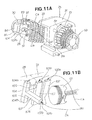
- the cooling air Wi flowing upward as shown by the arrow Ca is admitted into the top inlets 101a, 102a, 104a, as shown in FIGS. 11A, 11B , 12A, and 12B .
- the cooling air Wi flowing to the side as shown by the arrow Da is admitted into the inlet 107b.
- the cooling air Wi admitted into the top inlet 101a flows through the first cylinder-cooling duct 101 and then flows out from the bottom outlet 101b, as shown by the arrow Ea.
- the cooling air Wi admitted into the top inlet 102a flows through the second cylinder-cooling duct 102 and then flows out from the bottom outlet 102b, as shown by the arrow Fa.
- the cooling air Wi flows from the first lateral portion 33a to the top portion 33b of the cylinder block 33, as shown by the arrow Ca in FIG. 9 .
- the cooling air Wi that has flowed over the top portion 33b is admitted into the top inlet 102a and is caused to flow through the first cylinder-cooling duct 102 and then out from the bottom outlet 102b.
- cooling air Wi a large amount of cooling air Wi can be made to flow to the vicinity of the cylinder 26 because the cooling air Wi flows through two cooling ducts, which are the first and second cylinder-cooling ducts 101, 102. As a result, the area surrounding the cylinder 26 can be cooled efficiently by the cooling air Wi.
- the cooling air Wi admitted into the top inlet 104a flows through the head-cooling duct 104 and then out from the bottom outlet 104b, as shown by the arrow Ga. Admitting the cooling air Wi into the head-cooling duct 104 allows the cooling effects of the cylinder head 28 to be further improved. More specifically, the cooling air flows from the first lateral portion 28a of the cylinder head 28, as shown by the arrow in FIG. 10 . The cooling air that has flowed over the first lateral portion 28a is conducted through the top inlet 104a and is caused to flow through the head-cooling duct 104.
- the cooling air Wi admitted into the inlet 107b flows into the guide-cooling duct 107, enters the head-cooling duct 104, and mixes with the cooling air Wi from the top inlet 104a. Accordingly, a large amount of cooling air Wi can be made to flow through the head-cooling duct 104. Part of the cooling air Wi that flows through the head-cooling duct 104 passes through a pair of communicating channels 105, 105 and flows into the first cylinder-cooling duct 101, as shown by the arrow Ha.
- the cooling air Wi that has flowed over the cylinder head 28 can be adequately conducted to the cylinder block 33.
- the cooling'air Wi needed to cool the cylinder 26 can thereby be adequately conducted to the cylinder 26.
- Cooling air Wi can be allowed to flow in the vicinity of the combustion chamber 58 to efficiently cool both the cylinder head 28 and the cylinder block 33. This is achieved by conducting cooling air Wi to the head-cooling duct 104 and the first cylinder-cooling duct 101.
- the casing 25, the cylinder head 28, the case cover 32, the head cover 84, and the pulley cover 86, all shown in FIG. 3 are cast articles (die-cast, for example) made of an aluminum alloy.
- the axial line 109 of the cylinder 26 (the cylinder axis 109) is inclined upward at an angle ⁇ in relation to a horizontal line Lh passing through the crankshaft 12.
- e is the angle of inclination of the cylinder 26 in relation to the base 34.
- the casing 25 can be mounted on a mounting stand 121 (arbitrary mating member 121 or arbitrary mounting location 121) with bolts 122.
- the bolts 122 are the fastening members.
- the base 34 has first and second mounting holes 123, 124 at the left end 34a, and also has third and fourth mounting holes 125, 126 (the fourth mounting hole 126 is shown in FIG. 16 ) at the right end 34b. These four mounting holes 123 to 126 are aligned vertically (in the vertical direction) in the base 34.
- the first and third mounting holes 123, 125 are circular.
- the second and fourth mounting holes 124, 126 are slot-shaped.
- the base 34 can be attached to the mounting stand 121 by a plurality of bolts 122 that are inserted through each of the four mounting holes 123 to 126.
- the crank chamber 31d of the crank case 31 is a space enclosed by the first side 31b (back wall 31b), a peripheral wall 31c, and the flat plate-shaped base 34.
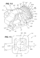
- the cylinder block 33 is integrally formed on the right side of the peripheral wall 31c. Furthermore, the cylinder block 33 has a plurality of cooling fins 141 formed integrally around the entire outer peripheral surface 33a.
- the cooling fins 141 encircle the outer peripheral surface 33a of the cylinder block 33, and have substantially square outline.
- the cooling fins 141 have a curved shape so that the top halves extend in a direction orthogonal to the cylinder axis 109, and the bottom halves extend vertically.
- the angle of inclination of the top halves of the cooling fins 141 is the same as the angle of inclination ⁇ of the cylinder axis 109.
- the cooling fins 141 are each composed of mutually connected top fin 142, bottom fin 143, and pair of left and right lateral fins 144; 144.
- the top fins 142 extend upward from the outer peripheral surface 33a of the cylinder block 33, so as to be orthogonal to the cylinder axis 109.
- the bottom fins 143 extend vertically downward from the outer peripheral surface 33a.
- the lateral fins 144 are curved and comprise slanted fins 151 at the top half and vertical fins 152 at the bottom half.
- the slanted fins 151 are the portions of the lateral fins 144 that extend from the top ends 144a to the curved parts 144b.
- the slanted fins 151 are formed so as to be orthogonal to the cylinder axis 109. Accordingly, the slanted fins 151 are formed at an incline to the vertical direction.
- the vertical fins 152 are the portions of the lateral fins 144 that extend from the curved parts 144b to the bottom ends 144c.
- the vertical fins 152 are bent towards the vertical direction at the curved parts 144b. Therefore, the vertical fins 152 are formed so as to be oriented in the same direction as the opening direction of the four mounting holes. 123 to 126 in the base 34. Specifically, the vertical fins 152 are formed parallel to the orientation of the mounting holes 123 to 126.
- the bottom fins 143 and the vertical fins 152 are formed so as to be parallel to the bore center BC of the mounting holes 123 to 126.
- the curved parts 144b are positioned below the cylinder axis 109 at a distance of H1 (see FIG. 13 ).
- the bottom halves of the cooling fins 141 i.e., the bottom fins 143 and the vertical fins 152, are oriented vertically, and the surfaces of the fins are thus disposed closer to the crank case 31 by the corresponding amount. Therefore, the bottom halves of the cooling fins 141 can be slanted towards the cooling fan 13.
- the top halves of the cooling fins 141 i.e., the "counter-base halves” on the side opposite from the base 34 relative to the cylinder axis 109, are composed of the top fins 142 and the slanted fins 151.
- the bottom halves of the cooling fins 141 i.e., the "base-side halves” disposed closer to the base 34 in relation to the cylinder axis 109, are composed of the bottom fins 143 and the vertical fins 152.
- the bottom ends of the counter-base halves and the top ends of the base-side halves are linked via the curved parts 144b.
- the cooling fan 13 has a plurality of blades 13a for blowing air.
- the distal end 13b of the bottommost.blade 13a among the plurality of blades 13a (the bottom end 13b of the cooling fan 13) is disposed below the plurality of cooling fins 141.
- a distance of H2 separates the bottom end 13b of the cooling fan 13 from the bottom end of the bottommost fin 143 among the plurality of bottom fins 143.
- the cooling fan 13 is configured so that rotation in the direction of the arrow Ar causes cooling air Wi to move towards the bottom halves of the cooling fins 141 (bottom fins 143 and vertical fins 152) from the bottom ends 13a (i.e., in the direction of the arrow Ba).
- the cooling air Wi is conducted by the fan cover 15 (see FIG. 2 ) so as to flow in the direction of the arrow Ba. Therefore, the cooling air Wi can be admitted between the plurality of cooling fins 141 from below the plurality of bottom fins 143.
- the bottom fins 143 are made to face the cooling fan 13, and the cooling air Wi blown from the cooling fan 13 can therefore be more smoothly conducted.
- the cooling air Wi admitted from the bottom fins 143 rises along the plurality of cooling fins 141, as shown by the arrow Ia, comes into extensive contact with the radiating surfaces of the cooling fins 141 and the outer peripheral surface 33a of the cylinder block 33 (see FIG. 14 ), and undergoes heat exchange. Therefore, the plurality of cooling fins 141 and the cylinder block 33 can be adequately cooled by the cooling air Wi.
- the top ends of the base-side halves of the cooling fins 141 i.e., the curved parts 144b, be positioned along the cylinder axis 109. The reasons for this are given hereinbelow.
- the flow speed of the cooling air Wi be increased by allowing the cooling air Wi to flow smoothly between the plurality of lateral fins 144 with minimal resistance. This can be achieved by making the lateral fins 144 totally linear without any curving in the middle. This means that the curved parts 144b would be dispensed with, and the lateral fins 144 would be configured solely from the vertical fins 152.
- one possibility is to increase the radiating surface area by increasing the number of cooling fins 141.
- the radiating surface area can be increased by disposing multiple cooling fins 141 at a narrow pitch Pi along the total limited length Ln of the cylinder block 33. In this case it is beneficial to dispense with the curved parts 144b and to configure the lateral fins 144 solely from the slanted fins 151.
- the restriction on the cooling fins 141 is that the base-side halves must be aligned parallel to the bore center BC of the mounting holes 123 to 126.
- the height H1 from the cylinder axis 109 shown in FIG. 13 to the curved parts 144b be a minimum value of 0 (zero). If the height H1 equals 0, then the curved parts 144b coincide with the cylinder axis 109.
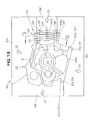
- FIG. 18 shows a view with the movable die 162 from FIG. 17 omitted in order to make the configuration easier to understand.
- a die-casting metal mold 160 is a metal mold for the die-casting of a casing 25.
- the mole includes a stationary die 161 for forming the back 25a of the casing 25, a movable die 162 for forming the front 25b of the casing 25, a top sliding die 163 for forming the top 25c of the casing 25, a right-end sliding die 164 for forming the right end 25d of the casing 25 and the cylinder 26, a bottom sliding die 165 for forming the bottom 25e of the casing 25, and a left-end sliding die 166 for forming the left end 25f of the casing 25.
- the stationary die 161 comprises a casting surface 161a for forming the back 25a of the casing 25, and is a metal mold whereby the rearward lateral fins 144 are formed using part 161b of the casting surface 161a.
- the movable die 162 is a metal mold that can be closed (clamped) and opened relative to the stationary die 161 in the direction of the arrow S1.
- the movable die 162 comprises a casting surface 162a for forming the front 25b of the casing 25, and is a metal mold whereby the forward lateral fins 144 are formed using part 162b of the casting surface 162a.
- the movable die 162 has a gate 168.
- the gate 168 is a channel for supplying molten metal into a cavity 167 (see FIG. 20A ).
- the top sliding die 163 is a die that can be closed and opened relative to the stationary die 161 in the direction of the arrow S2.
- This top sliding die 163 comprises a casting surface 163a for forming the top 25c of the casing 25, and is a metal mold whereby the top fins 142 are formed using part 163b of the casting surface 163a.
- the right-end sliding die 164 is a die that'can be closed and opened relative to the stationary die 161 in the direction of the arrow S3.
- This right-end sliding die 164 is a metal mold that comprises a core 164a for forming the cylinder 26.
- the bottom sliding die 165 is a die that can be closed and opened relative to the stationary die 161 in the direction of the arrow S4.
- This bottom sliding die 165 comprises a casting surface 165a for forming the bottom 25e of the casing 25, and is a metal mold whereby the base 34 and the bottom fins 143 are using part 165b of the casting surface 165a.
- the bottom sliding die 165 also comprises first, second, third, and fourth hole-forming areas 165c to 165f in the casting surface 165a.
- the first hole-forming area 165c is an area for forming the first mounting hole 123 in the base 25.
- the second hole-forming area 165d is an area for forming the second mounting hole 124 in the base 25.
- the third hole-forming area 165e is an area for forming the third mounting hole 125 in the base 25.
- the fourth hole-forming area 165f is an area for forming the fourth mounting hole 126 (see FIG. 16 ) in the base 25.
- the left-end sliding die 166 is a die that can be closed and opened relative to the stationary die 161 in the direction of the arrow S5.
- This left-end sliding die 166 comprises a casting surface 166a whereby the left end 25f of the casing 25 is cast.
- the die-casting metal mold 160 is closed, as shown in FIG. 20A .
- a molten aluminum alloy is fed under high pressure into the cavity 167 through the gate 168 of the movable die 162 (see FIG. 17 ).
- the solidification of the molten metal in the cavity 167 results in the formation of the casing 25 and the auxiliary parts of the casing 25, which are the top fins 142, the bottom fins 143, the lateral fins 144, 144, and the mounting holes 123 to 126.
- part 163b of the casting surface 163a in the top sliding die 163 is used to cast the top fins 142.
- Part 165b of the casting surface 165a in the bottom sliding die 165 is used to cast the bottom fins 143.
- Part 161b of the casting surface 161a in the stationary die 161 is used to cast the rearward lateral fins 144.
- Part 162b of the casting surface 162a in the movable die 162 is used to cast the forward lateral fins 144.
- the four hole-forming areas 165c to 165f of the bottom sliding die 165 are used to cast the four mounting holes 123 to 126.
- the die-casting metal mold 160 is then opened. Specifically, the movable die 162 shown in FIG. 17 is moved in the opening direction S1. Next, the top sliding die 163 and the right-end sliding die 164 are moved in the opening directions S2 and S3. Next, the bottom sliding die 165 and the left-end sliding die 166 are moved in the opening directions S4 and S5.
- opening the bottom sliding die 165 makes it possible for the bottom fin casting areas 165b to be separated from the bottom fins 143, and the four hole-forming areas 165c to 165f to be separated from the four mounting holes 123 to 126, as shown in FIG. 20B .
- the four mounting holes 123 to 126 can be formed in the casing 25 at the same time.
- the characteristics of the casing 25 and the die-casting metal mold 160 are summarized as follows.
- the bottom sliding die 165 comprises in the casting surface 165a the area 165b for forming the plurality of bottom fins 143 (the bottom fin casting area 165b), and the four hole-forming areas 165c to 165f for forming the four mounting holes 123 to 126.
- the opening direction (the arrow S4) of the bottom sliding die 165 is the same as the orientation of the four mounting holes 123 to 126 and the bottom fins 143, and also the orientation of the vertical fins 152. Therefore, as shown in FIG. 20A , after the molten metal in the cavity 167 solidifies, when the bottom sliding die 165 is opened in the direction of the arrow S4, the bottom fin casting area 165b can be separated from the bottom fins 143, and the four hole-forming areas 165c to 165f can be separated from the four mounting holes 123 to 126. As a result, the four mounting holes 123 to 126 can be formed in the casing 25 when the casing 25 is being cast in the die-casting metal mold 160.
- the bottom sliding die 165 with a new sliding die for forming the four mounting holes 123 to 126. Therefore, the cost of preparing the die-casting metal mold 160 can be reduced because the configuration of the bottom sliding die 165 can be simplified.
- Aluminum die casting used to die-cast the casing 25 from an aluminum alloy is a casting method in which a molten aluminum alloy is poured at high pressure into a metal mold. The precision with which the casing 25 is cast can be improved by die-casting the casing 25 from an aluminum alloy in this manner.
- counterbore surfaces in contact with the heads of the bolts 122 can be formed, e.g., on the edges of the openings in the four mounting holes 123 to 126. Therefore, the counterbore surfaces do not need to be mechanically worked into the edges of the four mounting holes 123 to 126 after the casing 25 is die-cast, and productivity can be further improved.
- the.cooling fan 13 sends cooling air Wi to the bottom fins 143 (in the direction of the arrow Ba).
- the bottom fins 143 are oriented towards the cooling fan 13, and the cooling air Wi sent from the cooling fan 13 can therefore be conducted adequately.
- the cooling air W1 conducted by the bottom fins 143 rises up along the bottom fins 143, as shown by the arrow Ia, and then flows around the outer peripheral surface 33a (see FIG. 15 ) of the cylinder block 33, whereby the area surrounding the cylinder 26 can be adequately cooled.
- the casing 25 was made by the die casting of an aluminum alloy, but the present invention is not limited thereto, and the casing can be die-cast from another material.
- the present invention can be appropriately applied to an air-cooled engine in which a power transmission mechanism for driving an intake valve and an exhaust valve is provided to the lateral portions of a cylinder head and a cylinder block.
- the present invention can be appropriately applied to an air-cooled engine having a tilted cylinder, wherein the base on the bottom of the crank case is provided with mounting holes through which fastening members can be inserted, and cooling fins are provided to the outer periphery of the cylinder block.
Landscapes
- Engineering & Computer Science (AREA)
- Mechanical Engineering (AREA)
- General Engineering & Computer Science (AREA)
- Chemical & Material Sciences (AREA)
- Combustion & Propulsion (AREA)
- Cylinder Crankcases Of Internal Combustion Engines (AREA)
- Compressor (AREA)
Abstract
Description
- The present invention relates to an air-cooled engine that is cooled by cooling air.
- Air-cooled engines are forcefully cooled by cooling air sent to a cylinder head and a cylinder block from a cooling fan that is driven by a crankshaft. This type of air-cooled engine is disclosed in Japanese Laid-Open Patent Application No.
2-275021 58-19293 - In the air-cooled engine disclosed in Japanese Laid-Open Patent Application No.
2-275021 - However, the power transmission mechanism is disposed on the side of the cylinder head and on the side of the cylinder block. Therefore, a compartment for accommodating the power transmission mechanism is disposed in the vicinity of the combustion chamber and the cylinder. This compartment is an obstacle to the cooling air being conducted to the vicinity of the combustion chamber and the cylinder.
- In order to resolve these problems, in the air-cooled engine in Japanese Laid-Open Patent Application No.
2-275021 - The need has also increased for techniques whereby cooling air can be more actively conducted to the vicinity of the combustion chamber and the cylinder to further improve the effects of cooling the combustion chamber and the cylinder.
- The air-cooled engine disclosed in Japanese Examined Utility Model Application No.
58-19293 - Also, the outer periphery of the cylinder block has a plurality of cooling fins extending in a direction perpendicular to the axial line of the cylinder. In this air-cooled engine, the cylinder can be cooled by the flow of cooling air among the plurality of cooling fins.
- The casing for the air-cooled engine is often a cast article wherein the crank case, the base, and the cylinder block are integrated in order to reduce manufacturing costs. When the casing is manufactured by casting, the metal mold is opened along the cooling fins after the molten metal in the cavity of the metal mold has solidified. However, since the cylinder block and cooling fins are inclined in relation to the base, the direction in which the metal mold opens is different from the orientation of the mounting holes of the base. When the casing is being cast, the mounting holes cannot be formed simultaneously. After the casing is cast, the mounting holes must be mechanically worked in. This places a limit on improving the productivity of the casing.
- One method for solving these problems is to provide the metal mold with a separate sliding die, and to form mounting holes by using this sliding die. This method allows the mounting holes to be formed at the same time as the casing is being cast. However, the structure of the metal mold becomes complicated with this method because a sliding die is provided to the metal mold.
- In view of this, the need has arisen for techniques whereby the mounting holes can be formed at the same time that the casing is cast and whereby the configuration of the metal mold can be simplified.
- The first embodiment of the present invention provides an air-cooled engine that is cooled by cooling air, comprising a cylinder block that comprises a cylinder having a reciprocating piston, and a cylinder head provided to a distal end of the cylinder block; wherein the cylinder block comprises at least one cylinder-cooling through-duct capable of transmitting the cooling air, on the periphery of the cylinder; the cylinder head comprises at least one head-cooling through-duct capable of transmitting the cooling air; and the cylinder-cooling ducts and the head-cooling duct extend in a direction perpendicular to the axial line of the cylinder, and are communicated with each other by means of at least one communicating channel formed on the cylinder block and the cylinder head.
- Therefore, the cylinder-cooling ducts can pass through the vicinity of the cylinder, and the head-cooling duct can pass through the vicinity of the combustion chamber even in an air-cooled engine in which the power transmission mechanism for transmitting the power of the crankshaft to the camshaft, and the compartment for accommodating the power transmission mechanism, are disposed on the side of the cylinder head and on the side of the cylinder block. The cooling air can then be conducted to the vicinity of the combustion chamber and the cylinder by being admitted into the cylinder-cooling ducts and the head-cooling duct. Therefore, the combustion chamber and the cylinder can be cooled even more efficiently.
- Furthermore, since the cylinder-cooling ducts and the cooling duct are communicated using communication channels, part of the cooling air flowing through the head-cooling duct can be admitted into the cylinder-cooling ducts and used as cooling air for the cylinder. Therefore, the cooling air needed to cool the cylinder can be adequately conducted to the cylinder. As a result, the cylinder cooling effect can be further improved.
- It is preferable that the cylinder-cooling ducts be composed of a plurality of ducts, and that the one cylinder-cooling duct from among this plurality of cylinder-cooling ducts that is adjacent to the head-cooling duct be communicated with the head-cooling duct via the communicating channels. Therefore, cooling air can be passed through the plurality of cylinder-cooling ducts, and the vicinity of the cylinder can be cooled. Moreover, a greater amount of cooling air can be admitted into the cylinder-cooling duct adjacent to the head-cooling duct, i.e., the cylinder-cooling duct nearest to the combustion chamber. Therefore, the effects of cooling can be further improved by conducting a greater amount of cooling air to the vicinity of the combustion chamber and the cylinder.
- The communication channels are preferably composed of a pair of separated communication channels. Therefore, part of the cooling air flowing through the head-cooling duct can be more adequately admitted into the cylinder-cooling ducts. As a result, the effects of cooling the cylinder can be further improved.
- It is also preferable that the cylinder head have a valve chamber for accommodating a camshaft that operates an intake valve and an exhaust valve, and a guide-cooling duct communicated with the head-cooling duct; that the camshaft be driven by a crankshaft via a power transmission mechanism disposed along the cylinder; and that an inlet for the guide-cooling duct be formed in the cylinder head on the side opposite from the power transmission mechanism. Therefore, cooling air can be admitted into the head-cooling duct via the guide-cooling duct from the side opposite from the power transmission mechanism as well. Accordingly, the effects of cooling the combustion chamber and the cylinder can be further improved because a greater amount of cooling air can be made to flow into the head-cooling duct. Moreover, since an inlet for the guide-cooling duct is provided to the cylinder head on the side opposite from the power transmission mechanism, the inlet can easily be made to face outward. Accordingly, there is a greater degree of freedom when designing the position and shape of the guide-cooling duct.
- The second embodiment of the present invention provides an air-cooled engine that is cooled by cooling air, comprising a crank case for accommodating a crankshaft, a cylinder block that is formed integrally on the crank case and is provided a cylinder having a reciprocating piston, and a base that is integrally formed on the crank case and can be mounted on arbitrary mating member by a plurality of fastening members; wherein the base has a plurality of mounting holes through which the fastening members can be inserted; the cylinder block is disposed at an incline in relation to the base and has a plurality of cooling fins formed integrally in the shape of a loop so as to encircle the outer periphery; and the cooling fins have the base-side halves disposed closer to the base in relation to the axial line of the cylinder and formed so as to be parallel to the center line of the mounting holes.
- Therefore, when the crank case, cylinder block, and base are cast (i.e., when the casing is cast) as an integrated casting, the metal mold can be opened along the base-side halves of the cooling fins, whereby the direction of opening the metal mold is aligned with the orientation of the mounting holes. Therefore, the mounting holes can be formed at the same time as the casing is being cast in the metal mold. Matching the opening direction of the metal mold with the orientation of the mounting holes in this manner makes it possible to shape the mounting holes at the same time that the casing is being cast in the metal mold. Moreover, there is no need to provide the metal mold with a sliding die for shaping the mounting holes, and the metal mold can be simplified.
- It is preferable that the cylinder block be disposed at a higher location than the base and be inclined upward in relation to the base; and that the engine also have a cooling fan for sending cooling air from the crank case to the base-side halves of the cooling fins. Therefore, the cooling air sent from the cooling fan can be more smoothly conducted to the cooling fins. Accordingly, the effects of cooling can be improved because the plurality of cooling fins and the cylinder block can be sufficiently cooled with cooling air. Furthermore, it is preferable that the cooling fan for blowing air has a plurality of blades, the plurality of blades have a bottommost blade, the bottommost blade has a distal end, and the distal end is disposed below the cooling fins.
- It is also preferable that the cooling fins have base-side halves, the base-side halves have top ends, and the top ends be positioned on the axial line of the cylinder.
- Certain preferred embodiments of the present invention will be described in detail below, by way of example only, with reference to the accompanying drawings, in which:
-
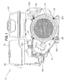
FIG. 1 is an external view of an air-cooled engine according to the present invention; -
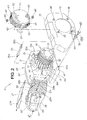
FIG. 2 is an exploded perspective view of the air-cooled engine shown inFIG. 1 ; -
FIG. 3 is a cross-sectional view of the air-cooled engine shown inFIG. 1 ; -
FIG. 4 is a cross-sectional view along the line 4-4 inFIG. 3 ; -
FIG. 5 is an exploded perspective view of the area surrounding the cylinder head in the air-cooled engine shown inFIG. 2 ; -
FIG. 6 is a view along thearrow line 6 inFIG. 2 ; -
FIG. 7 is a diagram describing the cooling ducts in the air-cooled engine shown inFIG. 2 ; -
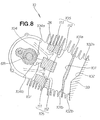
FIG. 8 is a cross-sectional view along the line 8-8 inFIG. 3 ; -
FIG. 9 is a cross-sectional view along the line 9-9 inFIG. 3 ; -
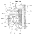
FIG. 10 is a view along thearrow 10 inFIG. 5 ; -
FIGS. 11A and 11B are diagrams describing the manner in which cooling air is conducted through the cooling ducts in the air-cooled engine shown inFIGS. 2 and7 ; -
FIGS. 12A and 12B are diagrams describing the manner in which cooling air flows through the cooling ducts shown inFIGS. 3 and8 ; -
FIG. 13 is a view of the air-cooled engine shown inFIG. 1 , as seen from the opposite side; -
FIG. 14 is a perspective view of the casing shown inFIG. 13 ; -
FIG. 15 is a view along thearrow 15 inFIG. 14 ; -
FIG. 16 is a perspective view showing the positional relationship between the cooling fan and the cooling fins shown inFIG. 2 ; -
FIG. 17 is an exploded perspective view of the metal mold for casting the casing shown inFIG. 14 ; -
FIG. 18 is an explanatory diagram showing an example in which the metal mold shown inFIG. 17 is closed; -
FIG. 19 is a cross-sectional view along the line 19-19 inFIG. 18 ; -
FIGS. 20A and 20B are diagrams describing an example of forming a casing by using the metal mold shown inFIG. 17 ; and -
FIG. 21 is a diagram describing an example in which cooling air is conducted by the cooling fins shown inFIG. 16 . - As shown in
FIGS. 1 and2 , the air-cooledengine 10 comprises a coolingfan 13, afan cover 15 that covers the coolingfan 13, arecoil starter 18, astarter cover 20 that covers therecoil starter 18, afuel tank 22, anair cleaner 23, and amuffler 24. - The cooling
fan 13 and therecoil starter 18 are linked with a crankshaft 12 (seeFIG. 3 ). Thefan cover 15 has anopening 16 through which therecoil starter 18 passes. - As shown in
FIGS. 2 and3 , the air-cooledengine 10 is a so-called OHC (overhead-cam) single-cylinder engine having a tilted cylinder, wherein asingle cylinder 26 and acylinder block 33 are tilted upward at fixed angles in relation to ahorizontal base 34 located at the bottom of a crankcase 31. The air-cooledengine 10 is described in detail hereinbelow. - The
casing 25 of the air-cooledengine 10 is composed of a crankcase 31, acase cover 32 that closes off the opening 31a of thecrank case 31, acylinder block 33 formed integrally on the side of the crank case 31 (the left end inFIG. 2 ), and ahorizontal base 34 formed integrally on the bottom of thecrank case 31. - The crank
case 31 has acrank chamber 31d (accommodatingspace 31d) that rotatably accommodates thecrankshaft 12. The opening 31a of thecrank case 31 can be covered with the case cover 32 by bolting the case cover 32 onto thecrank case 31. Thecrankshaft 12 has apower output unit 12a used to output the generated power and located at the end that extends through and past thecase cover 32. - The
cylinder block 33 and thecylinder 26 housed within thecylinder block 33 are tilted upward from the side portion of thecrank case 31. Therefore, thecylinder 26 and thecylinder block 33 are disposed farther up than the base 34, and are tilted upward in relation to thebase 34. - The crank
case 31 comprises three bosses 35 (only two are shown) on oneside 31b, and oneboss 41 disposed at a position separate from the threebosses 35, as shown inFIG. 2 . The threebosses 35 have the threadedparts 36a ofstud bolts 36 screwed intoscrew holes 35a. The threestud bolts 36 are thus mounted on oneside 31b of thecrank case 31. Thestud bolts 36 also have threadedparts 36b at their distal ends. - The procedure of attaching the
fan cover 15 and thestarter cover 20 is as follows. - First, the three threaded
parts 36b are inserted into three mountingholes 38 in thefan cover 15. At the same time, the position of a mounting hole 39 in thefan cover 15 is matched with ascrew hole 41a in aboss 41. - Next, the three threaded
parts 36b are inserted through the three mounting holes 43 (only two are shown) in thestarter cover 20. At the same time, abolt 44 in thefan cover 15 is inserted into a mountinghole 45 in thestarter cover 20. - Next, nuts 46 are screwed over the three threaded
parts 36b and thebolt 44. - Furthermore, a
bolt 48 is inserted through the mounting hole 39 in thefan cover 15, and a threadedpart 48a is screwed into thescrew hole 41a in theboss 41. - The
fan cover 15 can thus be attached to oneside 31b of thecrank case 31, and thestarter cover 20 can be attached to thefan cover 15. - As shown in
FIG. 2 , therecoil starter 18 includes apulley 51 linked with the crankshaft 12 (seeFIG. 3 ), and astarter rope 52 that is wound around thepulley 51. Thestarter rope 52 has agrip 53 at the distal end.FIG. 2 shows thegrip 53 as being detached from thestarter rope 52 and positioned on the side of thestarter cover 20, for the sake of simplicity. - As shown in
FIG. 2 , the air-cooledengine 10 comprises aguide cover 21 that covers the tops of both thecylinder head 28 and thecylinder block 33. Theguide cover 21 performs the function of guiding cooling air Wi from the coolingfan 13 along thetop portion 33b of thecylinder block 33. The cover is bolted onto thecylinder head 28 and thecylinder block 33. - Next, the cross-sectional structure of the air-cooled
engine 10 will be described. - As shown in
FIG. 3 , apiston 61 is reciprocatingly accommodated within thecylinder 26 and is linked with thecrankshaft 12 via a connectingrod 62. - As shown in
FIGS. 3 and4 , thecylinder head 28 is superposed on and bolted to the distal end surface of thecylinder block 33, i.e., thehead 33d.. Thecylinder head 28 is a member that closes off one end of thecylinder 26. Acombustion chamber 58 is formed in the area that faces thehead 33d, and avalve chamber 65 is formed adjacent to thecombustion chamber 58 on the side opposite from thecombustion chamber 58. Thevalve chamber 65 accommodates anintake valve 66, anexhaust valve 67, and acamshaft 68. - The
camshaft 68 is linked with thecrankshaft 12 via apower transmission mechanism 70. Thepower transmission mechanism 70 transmits drive force from thecrankshaft 12 to thecamshaft 68, and is disposed along thecylinder 26 and thecombustion chamber 58. Thepower transmission mechanism 70 is composed of adrive pulley 71 mounted on thecrankshaft 12, a drivenpulley 72 mounted on thecamshaft 68, and abelt 73 wound over thedrive pulley 71 and the drivenpulley 72. - The rotation of the
crankshaft 12 brings about rotation of thedrive pulley 71, thebelt 73, the drivenpulley 72, thecamshaft 68, and a pair ofcams intake valve 66 and theexhaust valve 67 operate to open and close an intake port and an exhaust port that face thecombustion chamber 58. Theintake valve 66 and theexhaust valve 67 can be opened and closed in synchronization with the rotation timing of thecrankshaft 12. - As shown in
FIG. 3 , thepower transmission mechanism 70 is accommodated in atransmission mechanism compartment 74. Thetransmission mechanism compartment 74 is composed ofbelt insertion slots pulley compartment 85, and apulley cover 86. Thebelt insertion slot 75 is formed on the otherlateral portion 33c of thecylinder block 33. Thebelt insertion slot 76 is formed on theother side 28b of thecylinder head 28. Thebelt 73 is passed through thebelt insertion slots - As shown in
FIGS. 5 and6 , thecylinder head 28 is an integrated casting composed of abase part 81, avalve compartment 83, thepulley compartment 85, and acoupler 89. - The
base part 81 is a flat discoid member that is superposed on theend surface 33f (flange surface 33f) of thecylinder block 33, and has anintake port 93 and an exhaust port 94 (see alsoFIG. 4 ). - The
valve compartment 83 is located on thesurface 81a of thebase part 81 on the side opposite from thecylinder block 33. The distalopen surface 83a (flange surface 83a) of thevalve compartment 83 is closed off by ahead cover 84. Thehead cover 84 is bolted onto thevalve compartment 83. The outer shape of thevalve compartment 83 is substantially rectangular when thevalve compartment 83 is viewed from the side of thehead cover 84. - The valve chamber 65 (see
FIG. 4 ) constitutes an internal space in thevalve compartment 83 that is closed off by thehead cover 84. As described above, theintake valve 66, theexhaust valve 67, and.thecamshaft 68 can be accommodated in thevalve chamber 65 inside thevalve compartment 83. It is apparent that thevalve compartment 83 has the internally disposedvalve chamber 65 and is therefore one size larger than the outer shape of thevalve chamber 65. - The
pulley compartment 85 is a member for accommodating the driven pulley 72 (seeFIG. 3 ), and the open end thereof is closed off by thepulley cover 86. More specifically, thepulley compartment 85 is placed at a specific distance Sp from the valve compartment 83 (i.e., the valve chamber 65) towards theother side 28b of thecylinder head 28, as shown inFIG. 6 . - Thus, at least part of the
transmission mechanism compartment 74, i.e., thepulley compartment 85 is formed in thecylinder head 28 at aspecific gap 87 from thevalve compartment 83. As a result, a space 87 (gap 87) having a specified dimension Sp can be maintained between thevalve compartment 83 and thepulley compartment 85, as shown inFIGS. 3 ,5 , and6 . The provision of thisspace 87 allows thevalve compartment 83 and thepulley compartment 85 to be integrally formed by means of thecoupler 89 through which thecamshaft 68 passes. - The
coupler 89 has a head-coolingduct 104 formed between thevalve compartment 83 and thepulley compartment 85. The head-coolingduct 104 serves as a duct through which cooling air flows. - As shown in
FIGS. 5 and6 , thebase part 81 has a plurality ofbosses 88 on thesurface 81a on the side opposite from thecylinder block 33. This plurality (four, for example) ofbosses 88 are disposed at the fourcorners 83b surrounding thevalve compartment 83. Thebosses 88 have a plurality of mountingholes 88a through which thebase part 81 is passed. The positions of the plurality of mountingholes 88a coincide with the positions of the plurality of screw holes 49 formed on theflange surface 33f of thecylinder block 33. - The procedure for fastening the
cylinder head 28 to thecylinder block 33 is as follows. - First, as shown in
FIGS. 4 and5 , a gasket 92 (seal member 92) is set into theflange surface 33f of thecylinder block 33, and thebase part 81 is superposed thereon. - Next, a plurality of head bolts 91 (hereinbelow referred to simply as "
bolts 91") are inserted into the plurality of mountingholes 88a from theend surface 81a of thebase part 81, and threadedportions 91a are allowed to protrude out and are screwed into the screw holes 49, completing the operation. - As described above, the four mounting
holes 88a and the fourbolts 91 are disposed nearer to the fourouter corners 83b away from thevalve compartment 83, i.e., in the areas outside of thevalve chamber 65. Therefore, the lubricating oil in thevalve chamber 65 does not pass through the mountingholes 88a and does not leak (seep out, for example) between thecylinder head 28 and thecylinder block 33. - Therefore, there is no need to adopt oil-sealing measures, such as placing a
gasket 92 with a complicated shape between thecylinder head 28 and thecylinder block 33, in order to prevent oil from leaking from thevalve chamber 65. The air-cooledengine 10 can therefore have a simpler structure. - Furthermore, since all of the
bolts 91 are disposed at the fourcorners 83b outside of thevalve compartment 83, the service conditions (temperature and the like) of thebolts 91 can be kept substantially identical. The thermal strain in thebolts 91 can be made uniform, and uniform and favorable thermal strain can therefore be preserved in thecylinder 26 and the combustion chamber 58 (seeFIG. 4 ). Moreover, the durability of thebolts 91 can be sufficiently improved because the thermal strain in thebolts 91 is uniform. - There is also no need to dispose the
bolts 91 inside thevalve chamber 65, because all thebolts 91 are disposed in areas outside of thevalve compartment 83. The size of the air-cooledengine 10 can be reduced by reducing the size of thevalve compartment 83 in proportion to the absence of the space for accommodating thebolts 91 in thevalve chamber 65. - Furthermore, since the
valve compartment 83 is smaller, it is possible to increase the surface area of the portion of thecylinder head 28 exposed in the vicinity of thecombustion chamber 58, i.e., the radiating surface area. Moreover, the distance from the outer surface of thevalve compartment 83 to thecombustion chamber 58 can be reduced because thevalve compartment 83 is smaller. Therefore, cooling air can be conducted to near thecombustion chamber 58. As a result, the area surrounding thecombustion chamber 58 in thecylinder head 28 can be cooled more adequately, and cooling efficiency can be improved. - Furthermore, the two left-
hand side bolts 91, 91 (some of the bolts) out of the fourbolts 91 are disposed between thevalve compartment 83 and thetransmission mechanism compartment 74. Therefore, the two left-handside head bolts valve compartment 83 in the same manner as the other twohead bolts bolts 91 can be made even more uniform. The thermal strain in all thebolts 91 can thereby be made more uniform. - Next, the cooling duct of the air-cooled
engine 10 will be described. - As shown in
FIG. 3 , thecylinder block 33 has two cylinder-coolingducts duct 101 and a second cylinder-coolingduct 102, for conducting cooling air to thearea 33e between thecylinder 26 and thebelt insertion slot 75. - As shown in
FIGS. 3 and7 through 9 , the first cylinder-coolingduct 101 is aligned vertically in a direction that intersects the axial line 109 (seeFIG. 7 ) of thecylinder 26. The first cylinder-coolingduct 101 has atop inlet 101a that opens into the top of thecylinder block 33, and abottom outlet 101b that opens into the bottom of thecylinder block 33. - The second cylinder-cooling
duct 102 is substantially parallel to the first cylinder-coolingduct 101, is disposed farther away from thecylinder head 28 than the first cylinder-coolingduct 101, and is aligned vertically. The second cylinder-coolingduct 102 has atop inlet 102a that opens into the top of thecylinder block 33, and abottom outlet 102b that opens into the bottom of thecylinder block 33. - The
cylinder head 28 has two coolingducts duct 104 and a guide-coolingduct 107, for conducting cooling air in the manner shown inFIGS. 3 ,7 ,8 , and10 . - The head-cooling
duct 104 is aligned vertically in thearea 28c between thevalve chamber 65 and thebelt insertion slot 76, and is substantially parallel to the first and second cylinder-coolingducts duct 104 has atop inlet 104a that opens into the top of thecylinder head 28, and abottom outlet 104b that opens into the bottom of thecylinder head 28. - As shown in
FIGS. 7 and8 , the head-coolingduct 104 is communicated with the first cylinder-coolingduct 101 by means of a pair of communicatingchannels channels 105 are composed of a head-side communicating channel 111 formed in thecylinder head 28, and a cylinder-side communicating channel 112 formed in thecylinder block 33. - As shown,in
FIGS. 3 ,7 , and8 , the guide-coolingduct 107 is formed in a direction substantially orthogonal to the head-coolingduct 104. This guide-coolingduct 107 has anoutlet 107a that is communicated with the substantial center of the head-coolingduct 104, and aninlet 107b that opens into thelateral portion 28a (seeFIG. 3 ) opposite from thepulley compartment 85, i.e., in the firstlateral portion 28a. Providing theinlet 107b to thelateral portion 28a opposite from thepulley compartment 85 makes it easier to make theinlet 107b face the exterior. Therefore, there is a high degree of freedom in designing the engine, and productivity can be improved because it is possible to easily set the shape of the guide-coolingduct 107 and the arrangement of the guide-coolingduct 107 in relation to thecylinder head 28. Moreover, cooling air can easily be admitted into the guide-coolingduct 107 from theinlet 107b. - A summary of the above description is as follows. As shown in
FIG. 7 , the first and second cylinder-coolingducts duct 104, and the guide-coolingduct 107 extend in a direction perpendicular to theaxial line 109 of thecylinder 26. The first cylinder-coolingduct 101 is adjacent to the head-coolingduct 104 and is communicated with the head-coolingduct 104 via the communicatingchannels - Next, the manner in which cooling air flows from the cooling
fan 13 will be described. - As shown in
FIG. 2 , the coolingfan 13 is rotated in the direction of the arrow Ar by the crankshaft 12 (seeFIG. 3 ). Therotating cooling fan 13 expels outside air that has been drawn in from theoutside air inlets lateral portion 33a of the cylinder block 33 (in the direction of the arrow Ba). The expelled outside air constitutes cooling air Wi for cooling the air-cooledengine 10. - Part of the cooling air Wi flows upward, as shown by the arrow Ca, from the first
lateral portion 33a of thecylinder block 33, and is conducted along thetop portion 33b of thecylinder block 33 by theguide cover 21. The cooling air Wi conducted along thetop portion 33b is directed downward by acurved part 21a of theguide cover 21. The cooling air Wi that has been directed downward is conducted down along the otherlateral portion 33c of thecylinder block 33 shown inFIG. 3 . - In
FIG. 2 , the remaining part of the cooling air Wi, moving as shown by the arrow Ba, is conducted as shown by the arrow Da along onelateral portion 28a of thecylinder head 28. - The cooling air Wi flowing upward as shown by the arrow Ca is admitted into the
top inlets FIGS. 11A, 11B ,12A, and 12B . The cooling air Wi flowing to the side as shown by the arrow Da is admitted into theinlet 107b. - The cooling air Wi admitted into the
top inlet 101a flows through the first cylinder-coolingduct 101 and then flows out from thebottom outlet 101b, as shown by the arrow Ea. The cooling air Wi admitted into thetop inlet 102a flows through the second cylinder-coolingduct 102 and then flows out from thebottom outlet 102b, as shown by the arrow Fa. - Specifically, the cooling air Wi flows from the first
lateral portion 33a to thetop portion 33b of thecylinder block 33, as shown by the arrow Ca inFIG. 9 . The cooling air Wi that has flowed over thetop portion 33b is admitted into thetop inlet 102a and is caused to flow through the first cylinder-coolingduct 102 and then out from thebottom outlet 102b. The same is true for the cooling air Wi that flows through the first cylinder-cooling duct 101 (seeFIGS. 12A and 12B ). - Thus, a large amount of cooling air Wi can be made to flow to the vicinity of the
cylinder 26 because the cooling air Wi flows through two cooling ducts, which are the first and second cylinder-coolingducts cylinder 26 can be cooled efficiently by the cooling air Wi. - As shown in
FIG. 12A , the cooling air Wi admitted into thetop inlet 104a flows through the head-coolingduct 104 and then out from thebottom outlet 104b, as shown by the arrow Ga. Admitting the cooling air Wi into the head-coolingduct 104 allows the cooling effects of thecylinder head 28 to be further improved. More specifically, the cooling air flows from the firstlateral portion 28a of thecylinder head 28, as shown by the arrow inFIG. 10 . The cooling air that has flowed over the firstlateral portion 28a is conducted through thetop inlet 104a and is caused to flow through the head-coolingduct 104. - As shown in
FIGS. 11B ,12A, and 12B , the cooling air Wi admitted into theinlet 107b flows into the guide-coolingduct 107, enters the head-coolingduct 104, and mixes with the cooling air Wi from thetop inlet 104a. Accordingly, a large amount of cooling air Wi can be made to flow through the head-coolingduct 104. Part of the cooling air Wi that flows through the head-coolingduct 104 passes through a pair of communicatingchannels duct 101, as shown by the arrow Ha. - Since the head-cooling
duct 104 and the first cylinder-coolingduct 101 are thus linked by a pair of communicatingchannels cylinder head 28 can be adequately conducted to thecylinder block 33. The cooling'air Wi needed to cool thecylinder 26 can thereby be adequately conducted to thecylinder 26. Cooling air Wi can be allowed to flow in the vicinity of thecombustion chamber 58 to efficiently cool both thecylinder head 28 and thecylinder block 33. This is achieved by conducting cooling air Wi to the head-coolingduct 104 and the first cylinder-coolingduct 101. - Next, the relationship between the tilted
cylinder block 33 and the base 34 in the air-cooledengine 10 will be described in detail. - The
casing 25, thecylinder head 28, thecase cover 32, thehead cover 84, and thepulley cover 86, all shown inFIG. 3 , are cast articles (die-cast, for example) made of an aluminum alloy. - As shown in
FIG. 13 , theaxial line 109 of the cylinder 26 (the cylinder axis 109) is inclined upward at an angle θ in relation to a horizontal line Lh passing through thecrankshaft 12. In other words, e is the angle of inclination of thecylinder 26 in relation to thebase 34. - As shown in
FIGS. 13 and14 , thecasing 25 can be mounted on a mounting stand 121 (arbitrary mating member 121 or arbitrary mounting location 121) withbolts 122. Thebolts 122 are the fastening members. - Specifically, the
base 34 has first and second mountingholes left end 34a, and also has third and fourth mountingholes 125, 126 (the fourth mountinghole 126 is shown inFIG. 16 ) at theright end 34b. These four mountingholes 123 to 126 are aligned vertically (in the vertical direction) in thebase 34. The first and third mountingholes holes stand 121 by a plurality ofbolts 122 that are inserted through each of the four mountingholes 123 to 126. - As shown in
FIG. 14 , thecrank chamber 31d of thecrank case 31 is a space enclosed by thefirst side 31b (back wall 31b), aperipheral wall 31c, and the flat plate-shapedbase 34. Thecylinder block 33 is integrally formed on the right side of theperipheral wall 31c. Furthermore, thecylinder block 33 has a plurality of coolingfins 141 formed integrally around the entire outerperipheral surface 33a. - As shown in
FIGS. 14 and 15 , the coolingfins 141 encircle the outerperipheral surface 33a of thecylinder block 33, and have substantially square outline. The coolingfins 141 have a curved shape so that the top halves extend in a direction orthogonal to thecylinder axis 109, and the bottom halves extend vertically. The angle of inclination of the top halves of the coolingfins 141 is the same as the angle of inclination θ of thecylinder axis 109. The coolingfins 141 are each composed of mutually connectedtop fin 142,bottom fin 143, and pair of left and rightlateral fins 144; 144. - As shown in
FIGS. 14 through 16 , thetop fins 142 extend upward from the outerperipheral surface 33a of thecylinder block 33, so as to be orthogonal to thecylinder axis 109. Thebottom fins 143 extend vertically downward from the outerperipheral surface 33a. Thelateral fins 144 are curved and comprise slantedfins 151 at the top half andvertical fins 152 at the bottom half. - As shown in
FIG. 14 , the slantedfins 151 are the portions of thelateral fins 144 that extend from the top ends 144a to thecurved parts 144b. The slantedfins 151 are formed so as to be orthogonal to thecylinder axis 109. Accordingly, the slantedfins 151 are formed at an incline to the vertical direction. - The
vertical fins 152 are the portions of thelateral fins 144 that extend from thecurved parts 144b to the bottom ends 144c. Thevertical fins 152 are bent towards the vertical direction at thecurved parts 144b. Therefore, thevertical fins 152 are formed so as to be oriented in the same direction as the opening direction of the four mounting holes. 123 to 126 in thebase 34. Specifically, thevertical fins 152 are formed parallel to the orientation of the mountingholes 123 to 126. - Thus, the
bottom fins 143 and thevertical fins 152 are formed so as to be parallel to the bore center BC of the mountingholes 123 to 126. - The
curved parts 144b are positioned below thecylinder axis 109 at a distance of H1 (seeFIG. 13 ). - As shown in
FIG. 16 , the bottom halves of the coolingfins 141, i.e., thebottom fins 143 and thevertical fins 152, are oriented vertically, and the surfaces of the fins are thus disposed closer to the crankcase 31 by the corresponding amount. Therefore, the bottom halves of the coolingfins 141 can be slanted towards the coolingfan 13. - As is made clear from the above description, the top halves of the cooling
fins 141, i.e., the "counter-base halves" on the side opposite from the base 34 relative to thecylinder axis 109, are composed of thetop fins 142 and the slantedfins 151. The bottom halves of the coolingfins 141, i.e., the "base-side halves" disposed closer to the base 34 in relation to thecylinder axis 109, are composed of thebottom fins 143 and thevertical fins 152. The bottom ends of the counter-base halves and the top ends of the base-side halves are linked via thecurved parts 144b. - As shown in
FIG. 16 , the coolingfan 13 has a plurality ofblades 13a for blowing air. Thedistal end 13b of thebottommost.blade 13a among the plurality ofblades 13a (thebottom end 13b of the cooling fan 13) is disposed below the plurality of coolingfins 141. Specifically, a distance of H2 separates thebottom end 13b of the coolingfan 13 from the bottom end of thebottommost fin 143 among the plurality ofbottom fins 143. - The cooling
fan 13 is configured so that rotation in the direction of the arrow Ar causes cooling air Wi to move towards the bottom halves of the cooling fins 141 (bottom fins 143 and vertical fins 152) from the bottom ends 13a (i.e., in the direction of the arrow Ba). For example, the cooling air Wi is conducted by the fan cover 15 (seeFIG. 2 ) so as to flow in the direction of the arrow Ba. Therefore, the cooling air Wi can be admitted between the plurality of coolingfins 141 from below the plurality ofbottom fins 143. - As described above, the
bottom fins 143 are made to face the coolingfan 13, and the cooling air Wi blown from the coolingfan 13 can therefore be more smoothly conducted. The cooling air Wi admitted from thebottom fins 143 rises along the plurality of coolingfins 141, as shown by the arrow Ia, comes into extensive contact with the radiating surfaces of the coolingfins 141 and the outerperipheral surface 33a of the cylinder block 33 (seeFIG. 14 ), and undergoes heat exchange. Therefore, the plurality of coolingfins 141 and thecylinder block 33 can be adequately cooled by the cooling air Wi. - It is more preferable that the top ends of the base-side halves of the cooling
fins 141, i.e., thecurved parts 144b, be positioned along thecylinder axis 109. The reasons for this are given hereinbelow. - First, to improve the cooling efficiency of the cooling
fins 141, it is preferable that the flow speed of the cooling air Wi be increased by allowing the cooling air Wi to flow smoothly between the plurality oflateral fins 144 with minimal resistance. This can be achieved by making thelateral fins 144 totally linear without any curving in the middle. This means that thecurved parts 144b would be dispensed with, and thelateral fins 144 would be configured solely from thevertical fins 152. - In order to increase the amount of heat radiated by the
cylinder block 33 and the coolingfins 141, one possibility is to increase the radiating surface area by increasing the number ofcooling fins 141. The radiating surface area can be increased by disposing multiple coolingfins 141 at a narrow pitch Pi along the total limited length Ln of thecylinder block 33. In this case it is beneficial to dispense with thecurved parts 144b and to configure thelateral fins 144 solely from the slantedfins 151. - However, the restriction on the cooling
fins 141 is that the base-side halves must be aligned parallel to the bore center BC of the mountingholes 123 to 126. To improve the flow of cooling air Wi and to arrangemultiple cooling fins 141 despite this restriction, it is preferable that the height H1 from thecylinder axis 109 shown inFIG. 13 to thecurved parts 144b be a minimum value of 0 (zero). If the height H1 equals 0, then thecurved parts 144b coincide with thecylinder axis 109. - Such measures make it possible for cooling air Wi to be more smoothly conducted upward along the cooling fins 47, and for multiple cooling
fins 141 to be arranged. As a result, the effects of cooling thecylinder 26 can be further improved. - Next, the die-casting metal mold for casting the
casing 25 of the air-cooledengine 10 will be described with reference toFIGS. 17 through 20A .FIG. 18 shows a view with themovable die 162 fromFIG. 17 omitted in order to make the configuration easier to understand. - As shown in
FIGS. 17 through 20A , a die-castingmetal mold 160 is a metal mold for the die-casting of acasing 25. The mole includes astationary die 161 for forming the back 25a of thecasing 25, amovable die 162 for forming the front 25b of thecasing 25, a top sliding die 163 for forming the top 25c of thecasing 25, a right-end sliding die 164 for forming theright end 25d of thecasing 25 and thecylinder 26, a bottom sliding die 165 for forming the bottom 25e of thecasing 25, and a left-end sliding die 166 for forming theleft end 25f of thecasing 25. - The
stationary die 161 comprises acasting surface 161a for forming the back 25a of thecasing 25, and is a metal mold whereby the rearwardlateral fins 144 are formed usingpart 161b of thecasting surface 161a. - The
movable die 162 is a metal mold that can be closed (clamped) and opened relative to thestationary die 161 in the direction of the arrow S1. Themovable die 162 comprises acasting surface 162a for forming the front 25b of thecasing 25, and is a metal mold whereby the forwardlateral fins 144 are formed usingpart 162b of thecasting surface 162a. Themovable die 162 has agate 168. Thegate 168 is a channel for supplying molten metal into a cavity 167 (seeFIG. 20A ). - The
top sliding die 163 is a die that can be closed and opened relative to thestationary die 161 in the direction of the arrow S2. This top slidingdie 163 comprises acasting surface 163a for forming the top 25c of thecasing 25, and is a metal mold whereby thetop fins 142 are formed usingpart 163b of thecasting surface 163a. - The right-end sliding die 164 is a die that'can be closed and opened relative to the
stationary die 161 in the direction of the arrow S3. This right-end sliding die 164 is a metal mold that comprises acore 164a for forming thecylinder 26. - The
bottom sliding die 165 is a die that can be closed and opened relative to thestationary die 161 in the direction of the arrow S4. Thisbottom sliding die 165 comprises acasting surface 165a for forming the bottom 25e of thecasing 25, and is a metal mold whereby thebase 34 and thebottom fins 143 are usingpart 165b of thecasting surface 165a. The bottom sliding die 165 also comprises first, second, third, and fourth hole-formingareas 165c to 165f in thecasting surface 165a. - The first hole-forming
area 165c is an area for forming the first mountinghole 123 in thebase 25. The second hole-formingarea 165d is an area for forming thesecond mounting hole 124 in thebase 25. The third hole-formingarea 165e is an area for forming the third mountinghole 125 in thebase 25. The fourth hole-formingarea 165f is an area for forming the fourth mounting hole 126 (seeFIG. 16 ) in thebase 25. - The left-end sliding die 166 is a die that can be closed and opened relative to the
stationary die 161 in the direction of the arrow S5. This left-end sliding die 166 comprises acasting surface 166a whereby theleft end 25f of thecasing 25 is cast. - Next, the procedure for casting the
casing 25 by using the die-castingmetal mold 160 will be described with reference toFIGS. 17 ,20A, and 20B . - First, the die-casting
metal mold 160 is closed, as shown inFIG. 20A . - Next, a molten aluminum alloy is fed under high pressure into the
cavity 167 through thegate 168 of the movable die 162 (seeFIG. 17 ). - Then, the solidification of the molten metal in the
cavity 167 results in the formation of thecasing 25 and the auxiliary parts of thecasing 25, which are thetop fins 142, thebottom fins 143, thelateral fins holes 123 to 126. - Specifically, as shown in
FIGS. 17 and20A ,part 163b of thecasting surface 163a in thetop sliding die 163 is used to cast thetop fins 142.Part 165b of thecasting surface 165a in thebottom sliding die 165 is used to cast thebottom fins 143.Part 161b of thecasting surface 161a in thestationary die 161 is used to cast the rearwardlateral fins 144.Part 162b of thecasting surface 162a in themovable die 162 is used to cast the forwardlateral fins 144. The four hole-formingareas 165c to 165f of the bottom sliding die 165 are used to cast the four mountingholes 123 to 126. - The die-casting
metal mold 160 is then opened. Specifically, themovable die 162 shown inFIG. 17 is moved in the opening direction S1. Next, thetop sliding die 163 and the right-end sliding die 164 are moved in the opening directions S2 and S3. Next, the bottom sliding die 165 and the left-end sliding die 166 are moved in the opening directions S4 and S5. - As a result, opening the
bottom sliding die 165 makes it possible for the bottomfin casting areas 165b to be separated from thebottom fins 143, and the four hole-formingareas 165c to 165f to be separated from the four mountingholes 123 to 126, as shown inFIG. 20B . - When the
casing 25 is being cast using the die-castingmetal mold 160 in this manner, the four mountingholes 123 to 126 can be formed in thecasing 25 at the same time. - The characteristics of the
casing 25 and the die-castingmetal mold 160 are summarized as follows. - Of the cooling
fins 141, thebottom fins 143 and thevertical fins 152 are oriented in the same vertical direction as the four mountingholes 123 to 126. In order to accommodate this, thebottom sliding die 165 comprises in thecasting surface 165a thearea 165b for forming the plurality of bottom fins 143 (the bottomfin casting area 165b), and the four hole-formingareas 165c to 165f for forming the four mountingholes 123 to 126. - The opening direction (the arrow S4) of the
bottom sliding die 165 is the same as the orientation of the four mountingholes 123 to 126 and thebottom fins 143, and also the orientation of thevertical fins 152. Therefore, as shown inFIG. 20A , after the molten metal in thecavity 167 solidifies, when thebottom sliding die 165 is opened in the direction of the arrow S4, the bottomfin casting area 165b can be separated from thebottom fins 143, and the four hole-formingareas 165c to 165f can be separated from the four mountingholes 123 to 126. As a result, the four mountingholes 123 to 126 can be formed in thecasing 25 when thecasing 25 is being cast in the die-castingmetal mold 160. - Therefore, there is no need to provide the bottom sliding die 165 with a new sliding die for forming the four mounting
holes 123 to 126. Therefore, the cost of preparing the die-castingmetal mold 160 can be reduced because the configuration of the bottom sliding die 165 can be simplified. - Aluminum die casting used to die-cast the
casing 25 from an aluminum alloy is a casting method in which a molten aluminum alloy is poured at high pressure into a metal mold. The precision with which thecasing 25 is cast can be improved by die-casting thecasing 25 from an aluminum alloy in this manner. - Moreover, when the
casing 25 is being die-cast, counterbore surfaces in contact with the heads of the bolts 122 (seeFIG. 16 ) can be formed, e.g., on the edges of the openings in the four mountingholes 123 to 126. Therefore, the counterbore surfaces do not need to be mechanically worked into the edges of the four mountingholes 123 to 126 after thecasing 25 is die-cast, and productivity can be further improved. - Next, the manner in which cooling air Wi flows through the air-cooled
engine 10 will be described. - As shown in
FIG. 21 ,the.cooling fan 13 sends cooling air Wi to the bottom fins 143 (in the direction of the arrow Ba). Thebottom fins 143 are oriented towards the coolingfan 13, and the cooling air Wi sent from the coolingfan 13 can therefore be conducted adequately. The cooling air W1 conducted by thebottom fins 143 rises up along thebottom fins 143, as shown by the arrow Ia, and then flows around the outerperipheral surface 33a (seeFIG. 15 ) of thecylinder block 33, whereby the area surrounding thecylinder 26 can be adequately cooled. - In the present invention, an example was described in which the
casing 25 was made by the die casting of an aluminum alloy, but the present invention is not limited thereto, and the casing can be die-cast from another material. - Also, an example was described in which two first and second cylinder-cooling
ducts - An example was also described in which the first cylinder-cooling
duct 101 and the head-coolingduct 104 were linked by a pair of communicatingchannels channels 105, for example. - The present invention can be appropriately applied to an air-cooled engine in which a power transmission mechanism for driving an intake valve and an exhaust valve is provided to the lateral portions of a cylinder head and a cylinder block.
- Furthermore, the present invention can be appropriately applied to an air-cooled engine having a tilted cylinder, wherein the base on the bottom of the crank case is provided with mounting holes through which fastening members can be inserted, and cooling fins are provided to the outer periphery of the cylinder block.
Claims (4)
- An air-cooled engine that is cooled by cooling air, the engine (10) comprising:a crank case (31) for accommodating a crankshaft (12);a cylinder block (33) that is formed integrally on the crank case (31) and is provided with a cylinder (26) having a reciprocating piston (61); anda base (34) that is integrally formed on the crank case (31) and can be mounted on arbitrary mating member by a plurality of fastening members; said air-cooled engine (10) is characterized in thatthe base (34) comprises a plurality of mounting holes (123, 124, 125, 126) through which the fastening members can be inserted; the cylinder block (33) is disposed at an incline in relation to the base (34) and has a plurality of cooling fins (141) formed integrally in the shape of a loop so as to encircle the outer periphery; andthe cooling fins (141) have base-side halves (143, 152) that are disposed closer to the base (34) in relation to the axial line (109) of the cylinder (26) and are formed so as to be parallel to the bore center of the mounting holes (123, 124, 125, 126).
- The air-cooled engine of claim 1,
characterized in that the cylinder block (33) is disposed at a higher location than the base (34) and is inclined upward in relation to the base (34); and the engine (10) also has a cooling fan (13) for sending cooling air from the crank case (31) to the base-side halves (143, 152) of the cooling fins (141). - The air-cooled engine of claim 2,
characterized in that the cooling fan (13) for blowing air has a plurality of blades (13a);
the plurality of blades have a bottommost blade (13a); the bottommost blade (13a) has a distal end; and the distal end is disposed below the cooling fins (141). - The air-cooled engine of claim 2,
characterized in that the cooling fins (141) have base-side halves (143, 152); the base-side halves (143, 152) have top ends; and the top ends are positioned on the axial line (109) of the cylinder (26).
Applications Claiming Priority (3)
| Application Number | Priority Date | Filing Date | Title |
|---|---|---|---|
| JP2005182813A JP4504261B2 (en) | 2005-06-23 | 2005-06-23 | Air-cooled engine with tilted cylinder |
| JP2005183166A JP4504263B2 (en) | 2005-06-23 | 2005-06-23 | Air-cooled engine |
| EP06767213A EP1902204B1 (en) | 2005-06-23 | 2006-06-16 | Air-cooled engine |
Related Parent Applications (2)
| Application Number | Title | Priority Date | Filing Date |
|---|---|---|---|
| EP06767213.9 Division | 2006-06-16 | ||
| EP06767213A Division EP1902204B1 (en) | 2005-06-23 | 2006-06-16 | Air-cooled engine |
Publications (3)
| Publication Number | Publication Date |
|---|---|
| EP2042703A2 true EP2042703A2 (en) | 2009-04-01 |
| EP2042703A3 EP2042703A3 (en) | 2009-04-08 |
| EP2042703B1 EP2042703B1 (en) | 2010-07-21 |
Family
ID=36954401
Family Applications (2)
| Application Number | Title | Priority Date | Filing Date |
|---|---|---|---|
| EP08021097A Not-in-force EP2042703B1 (en) | 2005-06-23 | 2006-06-16 | Air-cooled engine |
| EP06767213A Not-in-force EP1902204B1 (en) | 2005-06-23 | 2006-06-16 | Air-cooled engine |
Family Applications After (1)
| Application Number | Title | Priority Date | Filing Date |
|---|---|---|---|
| EP06767213A Not-in-force EP1902204B1 (en) | 2005-06-23 | 2006-06-16 | Air-cooled engine |
Country Status (15)
| Country | Link |
|---|---|
| US (1) | US7980205B2 (en) |
| EP (2) | EP2042703B1 (en) |
| KR (2) | KR100948540B1 (en) |
| CN (1) | CN102094700B (en) |
| AR (1) | AR055064A1 (en) |
| AU (2) | AU2006260179B2 (en) |
| BR (1) | BRPI0612527A2 (en) |
| CA (2) | CA2690211C (en) |
| CL (1) | CL2008003944A1 (en) |
| DE (2) | DE602006015720D1 (en) |
| ES (2) | ES2347497T3 (en) |
| MY (2) | MY144791A (en) |
| PE (2) | PE20100830A1 (en) |
| TW (1) | TWI359900B (en) |
| WO (1) | WO2006137505A2 (en) |
Families Citing this family (5)
| Publication number | Priority date | Publication date | Assignee | Title |
|---|---|---|---|---|
| CN101220764B (en) * | 2007-01-11 | 2011-06-22 | 光阳工业股份有限公司 | engine windshield |
| ITPE20100009A1 (en) * | 2010-03-17 | 2011-09-18 | Alessandro Pisciella | DESMODROMIC DISTRIBUTION SYSTEM WITH ROTATING ECCENTRIC VALVES |
| TWI421405B (en) * | 2011-10-25 | 2014-01-01 | Sanyang Industry Co Ltd | Locomotive engine cooling device |
| US9617951B2 (en) * | 2014-05-06 | 2017-04-11 | Champion Engine Technology, LLC | Air flow guide for an internal combustion engine |
| CN106077571B (en) * | 2016-08-10 | 2019-01-29 | 重庆东科模具制造有限公司 | A kind of cylinder head of gasoline engine and the die casting of cabinet |
Citations (2)
| Publication number | Priority date | Publication date | Assignee | Title |
|---|---|---|---|---|
| JPS5819293A (en) | 1981-07-27 | 1983-02-04 | 国際技術開発株式会社 | Garment dryer |
| JPH02275021A (en) | 1989-04-13 | 1990-11-09 | Honda Motor Co Ltd | Vertical crankshaft engine |
Family Cites Families (11)
| Publication number | Priority date | Publication date | Assignee | Title |
|---|---|---|---|---|
| DE893705C (en) * | 1950-07-27 | 1953-10-19 | Gustav Lauterjung | Multi-part casting mold, especially for light metal casting |
| GB814537A (en) * | 1955-08-08 | 1959-06-10 | Julius Mackerle | An air cooling arrangement for internal-combustion engines |
| DE1938297A1 (en) * | 1968-08-08 | 1971-02-11 | Honda Motor Co Ltd | Device for air cooling of internal combustion engines in motor vehicles |
| JPS5819293Y2 (en) | 1978-07-18 | 1983-04-20 | 株式会社クボタ | Inclined forced air cooled engine |
| JPS5949748U (en) | 1982-09-28 | 1984-04-02 | 本田技研工業株式会社 | Cylinder head cooling system |
| JPH01163414A (en) | 1987-12-18 | 1989-06-27 | Yamaha Motor Co Ltd | Device for cooling timing belt mechanism of engine |
| JP2691461B2 (en) | 1990-01-29 | 1997-12-17 | ヤンマーディーゼル株式会社 | Air-cooled internal combustion engine |
| JPH06346733A (en) | 1993-06-07 | 1994-12-20 | Yanmar Diesel Engine Co Ltd | Cooling mechanism for air-cooled engine |
| JP3815931B2 (en) * | 1999-11-16 | 2006-08-30 | 富士重工業株式会社 | engine |
| JP2002047934A (en) | 2000-08-04 | 2002-02-15 | Honda Motor Co Ltd | Cooling structure of internal combustion engine |
| CN2495820Y (en) * | 2001-08-23 | 2002-06-19 | 山东巨菱股份有限公司 | Single cylinder, horizontal arranged and air cooling type diesel engine |
-
2006
- 2006-06-13 MY MYPI20062775A patent/MY144791A/en unknown
- 2006-06-13 MY MYPI20093091A patent/MY143312A/en unknown
- 2006-06-16 EP EP08021097A patent/EP2042703B1/en not_active Not-in-force
- 2006-06-16 AU AU2006260179A patent/AU2006260179B2/en not_active Ceased
- 2006-06-16 CN CN2011100263427A patent/CN102094700B/en not_active Expired - Fee Related
- 2006-06-16 US US11/993,490 patent/US7980205B2/en active Active
- 2006-06-16 EP EP06767213A patent/EP1902204B1/en not_active Not-in-force
- 2006-06-16 CA CA2690211A patent/CA2690211C/en not_active Expired - Fee Related
- 2006-06-16 DE DE602006015720T patent/DE602006015720D1/en active Active
- 2006-06-16 CA CA2612493A patent/CA2612493C/en not_active Expired - Fee Related
- 2006-06-16 KR KR1020097015923A patent/KR100948540B1/en not_active Expired - Fee Related
- 2006-06-16 KR KR1020087001772A patent/KR20080021803A/en not_active Ceased
- 2006-06-16 DE DE602006015472T patent/DE602006015472D1/en active Active
- 2006-06-16 WO PCT/JP2006/312563 patent/WO2006137505A2/en not_active Ceased
- 2006-06-16 ES ES08021097T patent/ES2347497T3/en active Active
- 2006-06-16 TW TW095121609A patent/TWI359900B/en not_active IP Right Cessation
- 2006-06-16 BR BRPI0612527-1A patent/BRPI0612527A2/en not_active IP Right Cessation
- 2006-06-16 ES ES06767213T patent/ES2347469T3/en active Active
- 2006-06-22 PE PE2010000982A patent/PE20100830A1/en not_active Application Discontinuation
- 2006-06-22 AR ARP060102693A patent/AR055064A1/en active IP Right Grant
- 2006-06-22 PE PE2006000713A patent/PE20070302A1/en not_active Application Discontinuation
-
2008
- 2008-12-31 CL CL2008003944A patent/CL2008003944A1/en unknown
-
2009
- 2009-12-18 AU AU2009251044A patent/AU2009251044B2/en not_active Ceased
Patent Citations (2)
| Publication number | Priority date | Publication date | Assignee | Title |
|---|---|---|---|---|
| JPS5819293A (en) | 1981-07-27 | 1983-02-04 | 国際技術開発株式会社 | Garment dryer |
| JPH02275021A (en) | 1989-04-13 | 1990-11-09 | Honda Motor Co Ltd | Vertical crankshaft engine |
Also Published As
Similar Documents
| Publication | Publication Date | Title |
|---|---|---|
| US8418679B2 (en) | Charger module for an internal combustion engine | |
| AU2009251044B2 (en) | Air-cooled engine | |
| EP0567037B1 (en) | Air-cooled four-cycle engine | |
| JP2012062841A (en) | Liquid-cooled engine with cooling means | |
| EP1896715B1 (en) | Air-cooled engine | |
| US20020111088A1 (en) | Outboard motor | |
| CN101233306B (en) | Air-cooled engine | |
| CN103032126B (en) | Variable valve transmission device of internal combustion engine | |
| US11225929B2 (en) | Internal combustion engine | |
| EP2447496B1 (en) | Muffler mounting structure for an internal combustion engine | |
| JP2007002729A (en) | Air-cooled engine | |
| JP2000220519A (en) | OHC type air-cooled engine | |
| JPH0532753U (en) | Cylinder block structure of air-cooled engine | |
| JPH04103823A (en) | Cooling system for in-line multi-cylinder air-cooled engine |
Legal Events
| Date | Code | Title | Description |
|---|---|---|---|
| PUAI | Public reference made under article 153(3) epc to a published international application that has entered the european phase |
Free format text: ORIGINAL CODE: 0009012 |
|
| PUAL | Search report despatched |
Free format text: ORIGINAL CODE: 0009013 |
|
| 17P | Request for examination filed |
Effective date: 20081204 |
|
| AC | Divisional application: reference to earlier application |
Ref document number: 1902204 Country of ref document: EP Kind code of ref document: P |
|
| AK | Designated contracting states |
Kind code of ref document: A2 Designated state(s): DE ES FR GB IT SE |
|
| AK | Designated contracting states |
Kind code of ref document: A3 Designated state(s): DE ES FR GB IT SE |
|
| 17Q | First examination report despatched |
Effective date: 20090327 |
|
| AKX | Designation fees paid |
Designated state(s): DE ES FR GB IT SE |
|
| GRAP | Despatch of communication of intention to grant a patent |
Free format text: ORIGINAL CODE: EPIDOSNIGR1 |
|
| GRAS | Grant fee paid |
Free format text: ORIGINAL CODE: EPIDOSNIGR3 |
|
| GRAA | (expected) grant |
Free format text: ORIGINAL CODE: 0009210 |
|
| AC | Divisional application: reference to earlier application |
Ref document number: 1902204 Country of ref document: EP Kind code of ref document: P |
|
| AK | Designated contracting states |
Kind code of ref document: B1 Designated state(s): DE ES FR GB IT SE |
|
| REG | Reference to a national code |
Ref country code: GB Ref legal event code: FG4D |
|
| REF | Corresponds to: |
Ref document number: 602006015720 Country of ref document: DE Date of ref document: 20100902 Kind code of ref document: P |
|
| REG | Reference to a national code |
Ref country code: SE Ref legal event code: TRGR |
|
| REG | Reference to a national code |
Ref country code: ES Ref legal event code: FG2A Ref document number: 2347497 Country of ref document: ES Kind code of ref document: T3 |
|
| PLBE | No opposition filed within time limit |
Free format text: ORIGINAL CODE: 0009261 |
|
| STAA | Information on the status of an ep patent application or granted ep patent |
Free format text: STATUS: NO OPPOSITION FILED WITHIN TIME LIMIT |
|
| 26N | No opposition filed |
Effective date: 20110426 |
|
| REG | Reference to a national code |
Ref country code: DE Ref legal event code: R097 Ref document number: 602006015720 Country of ref document: DE Effective date: 20110426 |
|
| REG | Reference to a national code |
Ref country code: FR Ref legal event code: PLFP Year of fee payment: 11 |
|
| REG | Reference to a national code |
Ref country code: FR Ref legal event code: PLFP Year of fee payment: 12 |
|
| REG | Reference to a national code |
Ref country code: FR Ref legal event code: PLFP Year of fee payment: 13 |
|
| PGFP | Annual fee paid to national office [announced via postgrant information from national office to epo] |
Ref country code: IT Payment date: 20190527 Year of fee payment: 14 |
|
| PGFP | Annual fee paid to national office [announced via postgrant information from national office to epo] |
Ref country code: FR Payment date: 20190510 Year of fee payment: 14 |
|
| PGFP | Annual fee paid to national office [announced via postgrant information from national office to epo] |
Ref country code: GB Payment date: 20190612 Year of fee payment: 14 Ref country code: ES Payment date: 20190701 Year of fee payment: 14 |
|
| REG | Reference to a national code |
Ref country code: DE Ref legal event code: R084 Ref document number: 602006015720 Country of ref document: DE |
|
| REG | Reference to a national code |
Ref country code: GB Ref legal event code: 746 Effective date: 20191217 |
|
| GBPC | Gb: european patent ceased through non-payment of renewal fee |
Effective date: 20200616 |
|
| PG25 | Lapsed in a contracting state [announced via postgrant information from national office to epo] |
Ref country code: FR Free format text: LAPSE BECAUSE OF NON-PAYMENT OF DUE FEES Effective date: 20200630 Ref country code: GB Free format text: LAPSE BECAUSE OF NON-PAYMENT OF DUE FEES Effective date: 20200616 |
|
| PGFP | Annual fee paid to national office [announced via postgrant information from national office to epo] |
Ref country code: SE Payment date: 20210610 Year of fee payment: 16 |
|
| PG25 | Lapsed in a contracting state [announced via postgrant information from national office to epo] |
Ref country code: IT Free format text: LAPSE BECAUSE OF NON-PAYMENT OF DUE FEES Effective date: 20200616 |
|
| PG25 | Lapsed in a contracting state [announced via postgrant information from national office to epo] |
Ref country code: ES Free format text: LAPSE BECAUSE OF NON-PAYMENT OF DUE FEES Effective date: 20200617 |
|
| REG | Reference to a national code |
Ref country code: SE Ref legal event code: EUG |
|
| PG25 | Lapsed in a contracting state [announced via postgrant information from national office to epo] |
Ref country code: SE Free format text: LAPSE BECAUSE OF NON-PAYMENT OF DUE FEES Effective date: 20220617 |
|
| PGFP | Annual fee paid to national office [announced via postgrant information from national office to epo] |
Ref country code: DE Payment date: 20230418 Year of fee payment: 18 |
|
| REG | Reference to a national code |
Ref country code: DE Ref legal event code: R119 Ref document number: 602006015720 Country of ref document: DE |
|
| PG25 | Lapsed in a contracting state [announced via postgrant information from national office to epo] |
Ref country code: DE Free format text: LAPSE BECAUSE OF NON-PAYMENT OF DUE FEES Effective date: 20250101 |