EP2042666B1 - Fixing element and method for recessed mounting of an insulating board - Google Patents
Fixing element and method for recessed mounting of an insulating board Download PDFInfo
- Publication number
- EP2042666B1 EP2042666B1 EP08015937A EP08015937A EP2042666B1 EP 2042666 B1 EP2042666 B1 EP 2042666B1 EP 08015937 A EP08015937 A EP 08015937A EP 08015937 A EP08015937 A EP 08015937A EP 2042666 B1 EP2042666 B1 EP 2042666B1
- Authority
- EP
- European Patent Office
- Prior art keywords
- cap
- fastening element
- dowel sleeve
- pressing plate
- plate
- Prior art date
- Legal status (The legal status is an assumption and is not a legal conclusion. Google has not performed a legal analysis and makes no representation as to the accuracy of the status listed.)
- Active
Links
- 238000000034 method Methods 0.000 title claims description 7
- 239000011810 insulating material Substances 0.000 claims description 21
- 238000003780 insertion Methods 0.000 claims description 6
- 230000037431 insertion Effects 0.000 claims description 6
- 238000005553 drilling Methods 0.000 claims description 3
- 238000003801 milling Methods 0.000 description 21
- 238000009413 insulation Methods 0.000 description 20
- 239000012774 insulation material Substances 0.000 description 9
- 239000000428 dust Substances 0.000 description 8
- 238000005520 cutting process Methods 0.000 description 5
- 239000011505 plaster Substances 0.000 description 5
- 238000003892 spreading Methods 0.000 description 4
- 238000010276 construction Methods 0.000 description 3
- 238000004519 manufacturing process Methods 0.000 description 3
- 230000015572 biosynthetic process Effects 0.000 description 2
- 230000035515 penetration Effects 0.000 description 2
- 239000002699 waste material Substances 0.000 description 2
- 238000009825 accumulation Methods 0.000 description 1
- 230000006735 deficit Effects 0.000 description 1
- 230000000694 effects Effects 0.000 description 1
- 230000007613 environmental effect Effects 0.000 description 1
- 238000004904 shortening Methods 0.000 description 1
Images
Classifications
-
- E—FIXED CONSTRUCTIONS
- E04—BUILDING
- E04D—ROOF COVERINGS; SKY-LIGHTS; GUTTERS; ROOF-WORKING TOOLS
- E04D3/00—Roof covering by making use of flat or curved slabs or stiff sheets
- E04D3/36—Connecting; Fastening
- E04D3/3601—Connecting; Fastening of roof covering supported by the roof structure with interposition of a insulating layer
- E04D3/3603—Connecting; Fastening of roof covering supported by the roof structure with interposition of a insulating layer the fastening means being screws or nails
-
- B—PERFORMING OPERATIONS; TRANSPORTING
- B25—HAND TOOLS; PORTABLE POWER-DRIVEN TOOLS; MANIPULATORS
- B25B—TOOLS OR BENCH DEVICES NOT OTHERWISE PROVIDED FOR, FOR FASTENING, CONNECTING, DISENGAGING OR HOLDING
- B25B31/00—Hand tools for applying fasteners
-
- E—FIXED CONSTRUCTIONS
- E04—BUILDING
- E04B—GENERAL BUILDING CONSTRUCTIONS; WALLS, e.g. PARTITIONS; ROOFS; FLOORS; CEILINGS; INSULATION OR OTHER PROTECTION OF BUILDINGS
- E04B1/00—Constructions in general; Structures which are not restricted either to walls, e.g. partitions, or floors or ceilings or roofs
- E04B1/62—Insulation or other protection; Elements or use of specified material therefor
- E04B1/74—Heat, sound or noise insulation, absorption, or reflection; Other building methods affording favourable thermal or acoustical conditions, e.g. accumulating of heat within walls
- E04B1/76—Heat, sound or noise insulation, absorption, or reflection; Other building methods affording favourable thermal or acoustical conditions, e.g. accumulating of heat within walls specifically with respect to heat only
- E04B1/762—Exterior insulation of exterior walls
- E04B1/7629—Details of the mechanical connection of the insulation to the wall
- E04B1/7633—Dowels with enlarged insulation retaining head
Definitions
- the present invention relates to a fastener and a method for recessed mounting of an insulating plate to a substructure.
- the fastening element comprises a pressure plate and an adjoining dowel sleeve for receiving a spreading element with a Spreizelementkopf, wherein the dowel sleeve has a spreading zone and wherein a recess is milled into the insulation board.
- a depression corresponding to the diameter of the pressure plate is milled into the insulation plate by means of a countersunk drill, which comprises a milling head and a disk-shaped stop during drilling of the borehole in the same operation and then filled by an already applied to the pressure plate cover.
- a countersunk drill which comprises a milling head and a disk-shaped stop during drilling of the borehole in the same operation and then filled by an already applied to the pressure plate cover.
- the dowel sleeve has a spreading zone. Furthermore, the dowel includes cutting devices, which are arranged on the underside of the pressure plate, on the periphery thereof. The cutting devices are used to cut the insulation board when the pressure plate moves into the insulation board and compresses them.
- This dowel has proven to be very useful, however, the provision of the circumferential cutting devices on the pressure plate is associated with some effort in the production. In addition, the force required to compress the insulating material, depending on the type of insulation material used, be relatively high.
- a dowel device for recessed mounting a thermal insulation panel is disclosed on a wall.
- the dowel device is provided with a holding plate and an adjoining dowel shaft, wherein the dowel shaft is configured for receiving a spreader with a head and wherein the dowel shaft has a spreading area.
- radially extending ribs are arranged for milling the retaining plate in the thermal insulation board.
- a plurality of triangular openings are distributed uniformly over the circumference of the pressure plate. The milled dust produced during assembly is discharged to the outside due to the openings in the retaining plate, without being collected in any way.
- the invention is therefore an object of the invention to provide a fastener, which on the one hand almost completely prevents the pollution caused by the milling dust and on the other hand is less expensive to manufacture and with the required effort for assembly is reduced.
- the object is achieved by a fastener according to claim 1, a system according to claim 7 and a method according to claim 8.
- the collecting device is designed as a cap, which is connected to the pressure plate or connectable.
- the cap is particularly easy to produce from plastic. It may already be connected to the fastening element from the beginning, but it is also possible that the cap is connected to the pressure plate of the fastening element only during assembly. It is also conceivable that the cap is held with the device for driving over the pressure plate of the fastener.
- the cap absorbs the dust that accumulates during milling, and becomes flush with the surface of the Insulating plate sunk in the same. In other words, the cap acts as a rondel which remains together with the milled insulation material in the insulation board. In this way, no waste is generated and the environment is not burdened.
- the cap has on its upper side a layer of insulating material.
- This measure has the effect that the insulation can be improved or the formation of thermal bridges can be further prevented. Moreover, this is for the subsequent application of a plaster layer of advantage. There is also the possibility that the cap is formed entirely of insulating material.
- the cap has chambers for the orderly reception of the milled-out insulating material. In this way, a uniform accumulation of the milled-out insulating material in the chambers can be ensured.
- the cap via locking devices in height relative to the pressure plate is adjustable.
- the volume available for receiving the milled insulating material may be adjusted depending on the type and thickness of the insulating material used. It is thus also possible that the pressure plate can be mounted at different depths in the insulating material.
- the cap has an opening for receiving a screwing device.
- This opening is preferably formed by flexible lamellae, so that after pulling out of the driver from the borehole no hole remains in the cap, which later leads to dents in the plaster layer.
- the collecting device may be formed by a cover, which may be formed for example as a depth stop. If a fastener can be formed by a Teifenanschlag can. If a fastening element is mounted by means of such a device, the milling dust passing through the recesses of the pressure plate can be collected and collected.
- the device can also be designed so that it can have at its top a lid or a bag or the like, so as to be able to catch the milling dust - with the appropriate size, the milling dust of several mounted fasteners. The thus collected milling waste, which is a not insignificant factor in the amount of dowels which are used in the construction sector for fixing insulation boards, can be recycled for example via appropriate collection points.
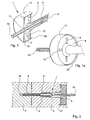
- the Figures 1 and 1a each show views of a pressure plate 4 of a fastener 1 according to the invention with an attached cap 11 as a collecting device for collecting insulation material.
- 4 milling devices 9 are arranged for milling the insulating plate 2 on the lower side in the insertion direction of the pressure plate and recesses 10 through which the milled insulation material can pass through; ie the recesses 10 go through the pressure plate 4 therethrough.
- the milling devices 9 are regularly formed as edges, which are arranged directly below the recesses 10 in order to achieve the most efficient possible removal of the milled insulating material.
- the recesses 10 and the milling devices 9 are arranged spatially separated from each other.
- the milling devices can also be designed as webs or rauflumbleige areas.
- the serving as a catch cap 11 can either be firmly connected to the pressure plate 4, by being approximately integrally made with the same or it can be releasably connected via (not shown) latching connections with the pressure plate, so that in their height relative to the pressure plate 4th is adjustable.
- the cap 11 is further equipped with an opening 13 for receiving a screw-14.
- the cap also has at its lower edge a circumferential cutting edge 22, which facilitates the penetration into the insulation board 2.
- the Cap 11 further forms one or more chambers 12 in which the milled insulation material is received.
- the expansion element 6 is introduced with the Spreizelementkopf 7 in a deep recess in the shank of the pressure plate 4, so as to be sunk deep in the insulating material itself. In this way, the formation of thermal bridges can be prevented.
- Fig. 2 shows the fastener 1 according to the invention in the assembled state.
- the pressure plate 4 is sunk in the insulation board 2 and the dowel sleeve 5 has been anchored in the region of the expansion zone 8 by the screwed-in by the screwing tool 14 expansion element 6 in the borehole 16 and the substructure 3.
- the insulating material milled out by the milling devices 9 has passed through the recesses 10 into the cap 11, where it continues to function as insulation against the outside.
- the cap 11 closes in the final assembly state flush with the surface of the insulating panel 2, in order to produce any unevenness in the plaster layer.
- the screw-in tool is withdrawn flexible fins can form the opening 13 of the cap 11, this hide again immediately, so that no hole in the cap 11 remains. This prevents dents in the plaster layer.
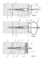
- FIGS. 3 and 4 show the fastener 1 according to the invention at the beginning of assembly.
- a hole 16 has already been drilled through the insulation board 2 in the substructure 3 and the dowel sleeve 5 and the expansion element 6 inserted into the borehole 16.
- the pressure plate 4 is now on the surface of the insulation board 2.
- the dowel sleeve 5 is inserted in the borehole 16 and the expansion element 6 is inserted to the expansion zone 8 in the dowel sleeve.
- the Einschraubtechnikmaschine which may include all common types of screwing instruments (such as a drill, a drive bit, etc.) is in engagement with a corresponding tool holder in Spreizelementkopf 7, so that now the driving of the expansion element 6 begins.
- the collecting device of the device 17 is formed by a cap 11 and an additional cover 15 in the form of a bag. It is also conceivable that the in Fig. 4 shown cap 11 is provided and only a bag or other adequate type of cover 15 is provided, such as an upwardly closed depth stop (not shown). By means of such a bag or depth stop the milled insulation material can be collected and recycled for environmental protection.
- a bag or depth stop By the way one recognizes from the Figures 2 . 3 and 4 in that the pressure plate 4 and the dowel sleeve 5 are formed in two parts. In Fig.
- the connection of dowel sleeve 5 and pressure plate 4 can also be realized via a predetermined breaking point or a bond.
- the shortening of the length of the fastening element may alternatively be provided a crumple zone between pressure plate 4 and anchor sleeve 5 (or only in the dowel sleeve 5).
- Fig. 5 shows an alternative embodiment of the fastener 1 according to the invention in the mounted state.
- the cap 11 with the circumferential cutting edge 22 protrudes slightly beyond the edge of the pressure plate 4 (this can already be provided during production or later achieved via the aforementioned snap connections), which facilitates penetration into the insulating material.
- a layer 18 of insulating material is arranged, which produces a, compared to the plastic cap 11, even more homogeneous outer surface. This can be advantageous for the application of the plaster layer.
Description
Die vorliegende Erfindung betrifft ein Befestigungselement sowie ein Verfahren zur vertieften Montage einer Dämmstoffplatte an einer Unterkonstruktion. Das Befestigungselement umfasst einen Druckteller und eine daran anschließende Dübelhülse zur Aufnahme eines Spreizelements mit einem Spreizelementkopf, wobei die Dübelhülse eine Spreizzone aufweist und wobei eine Vertiefung in die Dämmstoffplatte eingefräst wird.The present invention relates to a fastener and a method for recessed mounting of an insulating plate to a substructure. The fastening element comprises a pressure plate and an adjoining dowel sleeve for receiving a spreading element with a Spreizelementkopf, wherein the dowel sleeve has a spreading zone and wherein a recess is milled into the insulation board.
Ein Verfahren, bei dem gleichzeitig mit dem Bohren des Bohrlochs für den Dübel eine Vertiefung in der Dämmstoffplatte zur Aufnahme des Dübels erzeugt wird, ist aus
Aus der
Aus der
Der Erfindung liegt daher die Aufgabe zugrunde, ein Befestigungselement zu schaffen, welches einerseits die durch den Frässtaub bedingte Umweltverschmutzung nahezu vollständig unterbindet und andererseits in der Herstellung wenig aufwendig ist und mit dem der für die Montage benötigte Kraftaufwand reduziert wird.The invention is therefore an object of the invention to provide a fastener, which on the one hand almost completely prevents the pollution caused by the milling dust and on the other hand is less expensive to manufacture and with the required effort for assembly is reduced.
In Übereinstimmung mit der vorliegenden Erfindung wird die Aufgabe gelöst durch ein Befestigungselement gemäß Anspruch 1, ein System gemäß Anspruch 7 und ein Verfahren gemäß Anspruch 8.In accordance with the present invention, the object is achieved by a fastener according to
In einer bevorzugten Ausführungsform der Erfindung ist die Auffangvorrichtung als Kappe ausgebildet, welche mit dem Druckteller verbunden bzw. verbindbar ist. Die Kappe ist besonders einfach aus Kunststoff herstellbar. Sie kann bereits von Anfang an mit dem Befestigungselement verbunden sein, es besteht aber auch die Möglichkeit, dass die Kappe erst während der Montage mit dem Druckteller des Befestigungselements verbunden wird. Es ist auch denkbar, dass die Kappe mit der Vorrichtung zum Eintreiben über dem Druckteller des Befestigungselements gehalten wird. Die Kappe nimmt den beim Fräsen anfallenden Staub auf, und wird flächenbündig mit der Oberfläche der Dämmstoffplatte in derselben versenkt. Mit anderen Worten, die Kappe fungiert als Rondelle die mitsamt dem ausgefrästen Dämmstoffmaterial in der Dämmstoffplatte verbleibt. Auf diese Weise werden keinerlei Abfälle erzeugt und die Umwelt nicht belastet.In a preferred embodiment of the invention, the collecting device is designed as a cap, which is connected to the pressure plate or connectable. The cap is particularly easy to produce from plastic. It may already be connected to the fastening element from the beginning, but it is also possible that the cap is connected to the pressure plate of the fastening element only during assembly. It is also conceivable that the cap is held with the device for driving over the pressure plate of the fastener. The cap absorbs the dust that accumulates during milling, and becomes flush with the surface of the Insulating plate sunk in the same. In other words, the cap acts as a rondel which remains together with the milled insulation material in the insulation board. In this way, no waste is generated and the environment is not burdened.
In einer anderen bevorzugten Ausführungsform der Erfindung weist die Kappe an ihrer Oberseite eine Schicht aus Dämmstoffmaterial auf. Diese Maßnahme bewirkt, dass die Isolierung verbessert bzw. die Bildung von Wärmebrücken weiter unterbunden werden kann. Außerdem ist dies für die spätere Aufbringung einer Putzschicht von Vorteil. Es besteht darüber hinaus auch die Möglichkeit, dass die Kappe ganz aus Dämmstoffmaterial gebildet wird.In another preferred embodiment of the invention, the cap has on its upper side a layer of insulating material. This measure has the effect that the insulation can be improved or the formation of thermal bridges can be further prevented. Moreover, this is for the subsequent application of a plaster layer of advantage. There is also the possibility that the cap is formed entirely of insulating material.
In einer noch weiteren bevorzugten Ausführungsform der Erfindung weist die Kappe Kammern zur geordneten Aufnahme des ausgefrästen Dämmstoffmaterials auf Hierdurch kann eine gleichmäßige Ansammlung des ausgefrästen Dämmstoffinaterials in den Kammern gewährleistet werden.In yet another preferred embodiment of the invention, the cap has chambers for the orderly reception of the milled-out insulating material. In this way, a uniform accumulation of the milled-out insulating material in the chambers can be ensured.
In einer anderen bevorzugten Ausführungsform der Erfindung ist die Kappe über Rastvorrichtungen in ihrer Höhe gegenüber dem Druckteller verstellbar. Auf diese Weise kann das Volumen, welches zur Aufnahme des ausgefrästen Dämmstoffinaterials zur Verfügung steht, in Abhängigkeit von der Art und Dicke des verwendeten Dämmstoffs angepasst werden. Es ist dadurch auch möglich, dass der Druckteller verschieden tief im Dämmstoff montiert werden kann.In another preferred embodiment of the invention, the cap via locking devices in height relative to the pressure plate is adjustable. In this way, the volume available for receiving the milled insulating material may be adjusted depending on the type and thickness of the insulating material used. It is thus also possible that the pressure plate can be mounted at different depths in the insulating material.
In einer weiteren bevorzugten Ausführungsform der Erfindung weist die Kappe eine Öffnung zur Aufnahme einer Einschraubvorrichtung auf. Diese Öffnung wird vorzugsweise durch flexible Lamellen gebildet, damit nach dem Herausziehen des Eintreibgeräts aus dem Bohrloch kein Loch in der Kappe verbleibt, was später zu Dellen in der Putzschicht führt.In a further preferred embodiment of the invention, the cap has an opening for receiving a screwing device. This opening is preferably formed by flexible lamellae, so that after pulling out of the driver from the borehole no hole remains in the cap, which later leads to dents in the plaster layer.
Die Auffangvorrichtung kann durch eine Abdeckung gebildet, werden die beispielsweise als Tiefenanschlag ausgebildet sein kann. Wird ein Befestigungselement mittels einer Teifenanschlag ausgebildet sein Kann. Wird ein Befestigungselement mittels einer solchen Vorrichtung montiert, kann der durch die Ausnehmungen des Drucktellers hindurch tretende Frässtaub aufgefangen und gesammelt werden. Die Vorrichtung kann weiterhin so gestaltet sein, dass sie an ihrer Oberseite einen Deckel oder einen Beutel oder ähnliches aufweisen kann, um so den Frässtaub - bei entsprechender Größe auch den Frässtaub mehrerer montierter Befestigungselemente - auffangen zu können. Der so gesammelte Fräsabfall, der bei der Menge der Dübel welche im Baubereich zur Befestigung von Dämmstoffplatten zum Einsatz kommen, einen nicht unwesentlichen Faktor darstellt, kann etwa über entsprechende Sammelstellen dem Recycling zugeführt werden.The collecting device may be formed by a cover, which may be formed for example as a depth stop. If a fastener can be formed by a Teifenanschlag can. If a fastening element is mounted by means of such a device, the milling dust passing through the recesses of the pressure plate can be collected and collected. The device can also be designed so that it can have at its top a lid or a bag or the like, so as to be able to catch the milling dust - with the appropriate size, the milling dust of several mounted fasteners. The thus collected milling waste, which is a not insignificant factor in the amount of dowels which are used in the construction sector for fixing insulation boards, can be recycled for example via appropriate collection points.
Anhand der Zeichnungen wird die Montage eines erfindungsgemäßen Befestigungselements veranschaulicht. Es zeigen:
- Fig. 1
- eine perspektivische Schnittansicht eines Drucktellers eines erfindungsgemäßen Befestigungssystems mit aufgesetzter Kappe und eingebrachtem Einschraubwerkzeug;
- Fig. 1a
- eine perspektivische Unteransicht eines Drucktellers eines erfindungsgemäßen Befestigungssystems mit Ausnehmungen und Fräsvorrichtungen;
- Fig.2
- eine Querschnittsansicht eines montierten erfindungsgemäßen Befestigungselements mit aufgesetzter Kappe;
- Fig. 3
- eine Querschnittsansicht eines durch die Dämmstoffplatte und in das Bohrloch eingesteckten erfindungsgemäßen Befestigungselements vor der Montage durch ein Eintreibwerkzeug;
- Fig. 4
- ein erfindungsgemäßes Befestigungselement in derselben Position wie in
Fig. 3 , welches von einer Vorrichtung mit einer Abdeckung eingetrieben wird; - Fig. 5
- eine alternative Form des erfindungsgemäßen Befestigungselements im montierten Zustand, welches auf der Kappe eine Schicht aus Dämmstoffmaterial aufweist.
- Fig. 1
- a sectional perspective view of a pressure plate of a fastening system according to the invention with attached cap and introduced Einschraubwerkzeug;
- Fig. 1a
- a bottom perspective view of a pressure plate of a fastening system according to the invention with recesses and milling devices;
- Fig.2
- a cross-sectional view of a mounted fastener according to the invention with attached cap;
- Fig. 3
- a cross-sectional view of a plugged through the insulation plate and into the borehole fastener according to the invention prior to assembly by a driving tool;
- Fig. 4
- an inventive fastener in the same position as in
Fig. 3 which is driven by a device with a cover; - Fig. 5
- an alternative form of the fastener according to the invention in the assembled state, which has a layer of insulating material on the cap.
Die
Die
Claims (8)
- Fastening element (1) for deep installing an insulating plate (2) to a substructure (3), wherein the fastening element (1) has a pressure plate (4) and an adjacent dowel sleeve (5), wherein the dowel sleeve (5) is suitable to receive an expansion element (6) with an expansion element head (7), and wherein the dowel sleeve (5) comprises an expansion zone (8), wherein
at the lower side of the pressing plate (4), in direction of insertion, carving devices (9) for carving out the insulating plate (2) are arranged as well as recesses (10) through which the carved out insulating material can pass
characterized in that
the carved out insulating material is collected in a collecting device, wherein the collecting device is formed as cap (11), which is connectable to the pressing plate (4). - Fastening element (1) according to claim 1, characterized in that the cap (11) on its upper side comprises a layer of insulating material.
- Fastening element (1) according to any of the preceding claims, characterized in that the cap (11) comprises chambers (12) for orderly receiving the carved out insulating material.
- Fastening element (1) according to any of the preceding claims, characterized in that the cap (11) comprises locking devices, which are height adjustable in relation to the pressure plate (4).
- Fastening element (1) according to any of the preceding claims, characterized in that the cap (11) has an opening (13) for receiving a screwing device.
- Fastening element according to claim 5, characterized in that the opening (13) is formed by flexible fins.
- System comprising a device (14, 17) for driving in a fastening element and a fastening element (1), wherein the fastening element (1) has a pressing plate (4) and an adjacent dowel sleeve (5), wherein the dowel sleeve (5) is suitable to receive an expansion element (6) with an expansion element head (7), and wherein the dowel sleeve (5) comprises an expansion zone (8), and wherein at the lower side of the pressing plate (4), in direction of insertion, carving devices (9) for carving out an insulating plate (2) are arranged, as well as recesses (10) through which the carved out insulating material can pass, and wherein the device (14, 17) comprises a drive for gripping into the expansion element (6)
characterized in that
the device (14, 17) comprises a collecting device for collecting the carved out insulating material passed through recesses (10) in pressing plate (4) of the fastening element (1), which is formed as bag or depth stop, which is closed to the top. - Method for deep installing an insulating plate (2) to a substructure (3) by means of a fastening element (1), wherein the fastening element (1) has a pressing plate (4) and an adjacent dowel sleeve (5), wherein the dowel sleeve (5) is suitable to receive an expansion element (6) with an expansion element head (7), and wherein the dowel sleeve (5) comprises an expansion zone (8), the method comprises at least the steps of:a) drilling of a borehole (16) through the insulating plate (2) into the substructure (3);b) inserting the dowel sleeve (5) and the expansion element (6) into the borehole (16);c) driving in the expansion element (6) with a driving device (14, 17);d) carving out the insulating plate (2) by means of carving devices (9) arranged at the lower side of the pressing plate (4), in direction of insertion, and characterized by simultaneouslye) collecting carved out insulating material passing through recesses (10) in the pressing plate (4) into a collecting device, wherein the collecting device is formed as cap (11), which is connectable to the pressing plate (4) or in a collecting device of the driving device (14, 17), which is formed as bag or as depth stop, which is closed to the top;f) sink the cap (11), respectively, the pressing plate (4) into the insulating plate (2).
Priority Applications (2)
| Application Number | Priority Date | Filing Date | Title |
|---|---|---|---|
| SI200830684T SI2042666T1 (en) | 2007-09-27 | 2008-09-10 | Fixing element and method for recessed mounting of an insulating board |
| PL08015937T PL2042666T3 (en) | 2007-09-27 | 2008-09-10 | Fixing element and method for recessed mounting of an insulating board |
Applications Claiming Priority (1)
| Application Number | Priority Date | Filing Date | Title |
|---|---|---|---|
| DE102007046323A DE102007046323B3 (en) | 2007-09-27 | 2007-09-27 | Fastening element and method for recessed mounting of an insulation board |
Publications (3)
| Publication Number | Publication Date |
|---|---|
| EP2042666A2 EP2042666A2 (en) | 2009-04-01 |
| EP2042666A3 EP2042666A3 (en) | 2010-05-19 |
| EP2042666B1 true EP2042666B1 (en) | 2012-04-11 |
Family
ID=40121799
Family Applications (1)
| Application Number | Title | Priority Date | Filing Date |
|---|---|---|---|
| EP08015937A Active EP2042666B1 (en) | 2007-09-27 | 2008-09-10 | Fixing element and method for recessed mounting of an insulating board |
Country Status (10)
| Country | Link |
|---|---|
| EP (1) | EP2042666B1 (en) |
| AT (2) | AT13300U3 (en) |
| DE (2) | DE102007046323B3 (en) |
| DK (1) | DK2042666T3 (en) |
| ES (1) | ES2388146T3 (en) |
| PL (1) | PL2042666T3 (en) |
| PT (1) | PT2042666E (en) |
| RU (1) | RU2394133C2 (en) |
| SI (1) | SI2042666T1 (en) |
| UA (1) | UA99436C2 (en) |
Cited By (2)
| Publication number | Priority date | Publication date | Assignee | Title |
|---|---|---|---|---|
| EP2915929A1 (en) | 2014-03-07 | 2015-09-09 | RANIT-Befestigungssysteme GmbH | Method and fastening system for attaching, in particular mineral wool panels to a supporting base |
| EP2959995A1 (en) | 2014-06-23 | 2015-12-30 | EJOT Baubefestigungen GmbH | Assembly tool and a method for arranging a recessed dowel plate |
Families Citing this family (13)
| Publication number | Priority date | Publication date | Assignee | Title |
|---|---|---|---|---|
| DE102011016383A1 (en) | 2010-04-15 | 2011-12-15 | Ranit Befestigungssysteme Gmbh | Method and tool and cover for mounting an insulation board on a substructure |
| EP2639374B1 (en) | 2012-03-16 | 2018-06-13 | EJOT Baubefestigungen GmbH | Mounting of insulation boards |
| PL223205B1 (en) * | 2012-07-10 | 2016-10-31 | Koelner Rawlplug Ip Spółka Z Ograniczoną Odpowiedzialnością | Mounting kit for wall insulation |
| PL230393B1 (en) * | 2012-07-13 | 2018-10-31 | Koelner Rawlplug Ip Spolka Z Ograniczona Odpowiedzialnoscia | Mounting kit for wall insulation |
| PL2740851T3 (en) | 2012-12-05 | 2017-08-31 | Ejot Baubefestigungen Gmbh | Spreading element with a cover panel |
| DE102013103395A1 (en) * | 2013-04-05 | 2014-10-09 | Fischerwerke Gmbh & Co. Kg | Setting tool and its combination with a fastener |
| EP2796633B1 (en) * | 2013-04-25 | 2016-11-02 | EJOT Baubefestigungen GmbH | Device and method for fixing an insulation panel with simultaneous heat insulation closure |
| DE102013208954A1 (en) * | 2013-05-15 | 2014-08-14 | E.G.O. Elektro-Gerätebau GmbH | Fastener and method for fixing an insulation board and appropriate arrangement |
| DE102014101493A1 (en) * | 2014-02-06 | 2015-08-06 | Fischerwerke Gmbh & Co. Kg | Dowel, setting tool and method for fixing insulating materials |
| EP2977135B1 (en) | 2014-07-23 | 2018-04-18 | EJOT Baubefestigungen GmbH | Device and method for creating a recess in insulating materials |
| SI3138974T1 (en) | 2015-08-20 | 2020-02-28 | Ranit Austria Gmbh | Fastening system for attaching insulating boards or similar insulating material to a supporting base |
| PL242482B1 (en) | 2016-09-29 | 2023-02-27 | Koelner Rawlplug Ip Spolka Z Ograniczona Odpowiedzialnoscia | Device for fixing the connector fastening the thermally insulating panel to the wall |
| PL71773Y1 (en) * | 2018-02-23 | 2021-01-25 | Desol Agnieszka | Milling cutter with decanter for expanded polystyrene shavings, intended for making cavities for assembly pegs in the building facade external thermal insulation system |
Family Cites Families (6)
| Publication number | Priority date | Publication date | Assignee | Title |
|---|---|---|---|---|
| DE3365762D1 (en) * | 1982-02-12 | 1986-10-09 | Faester Gmbh & Co Kg | Method of fixing an insulating slab to be plastered to a building surface |
| DE10159632B4 (en) * | 2001-12-05 | 2006-11-16 | Ejot Kunststofftechnik Gmbh & Co. Kg | Dowels and method for mounting insulation boards and a device for driving a spreader into a dowel |
| DE50307497D1 (en) * | 2002-04-24 | 2007-07-26 | Mungo Befestigungstech Ag | Insulation plate |
| DE10361751A1 (en) * | 2002-12-29 | 2004-07-15 | Burkhart Schurig | Dowel for fastening of facade components on heat insulating layers has housing for external fastening component, opening for plaster penetrations, and also ribs or edgings running sharp edged to insulating material surface |
| DE102004005582A1 (en) * | 2004-02-05 | 2005-08-25 | Veit Dennert Kg Baustoffbetriebe | Dowel device for anchoring heat-insulating plates to buildings comprises a spreading element having a head fixed in a form- and/or friction-locking manner to the inner end of a dowel shaft |
| DE102004006936A1 (en) * | 2004-02-12 | 2005-09-01 | Friedr. Trurnit Gmbh | Method for securing insulation panels using a special tool with fitted hole saw and central driving bit for a recessed fitting of the fasteners into the panels |
-
2007
- 2007-09-27 DE DE102007046323A patent/DE102007046323B3/en active Active
-
2008
- 2008-09-10 PL PL08015937T patent/PL2042666T3/en unknown
- 2008-09-10 DK DK08015937.9T patent/DK2042666T3/en active
- 2008-09-10 EP EP08015937A patent/EP2042666B1/en active Active
- 2008-09-10 AT ATGM50090/2013U patent/AT13300U3/en not_active IP Right Cessation
- 2008-09-10 SI SI200830684T patent/SI2042666T1/en unknown
- 2008-09-10 DE DE202008018402U patent/DE202008018402U1/en not_active Expired - Lifetime
- 2008-09-10 AT AT08015937T patent/ATE553270T1/en active
- 2008-09-10 ES ES08015937T patent/ES2388146T3/en active Active
- 2008-09-10 PT PT08015937T patent/PT2042666E/en unknown
- 2008-09-25 RU RU2008138140/03A patent/RU2394133C2/en not_active IP Right Cessation
- 2008-09-29 UA UAA200811629A patent/UA99436C2/en unknown
Cited By (2)
| Publication number | Priority date | Publication date | Assignee | Title |
|---|---|---|---|---|
| EP2915929A1 (en) | 2014-03-07 | 2015-09-09 | RANIT-Befestigungssysteme GmbH | Method and fastening system for attaching, in particular mineral wool panels to a supporting base |
| EP2959995A1 (en) | 2014-06-23 | 2015-12-30 | EJOT Baubefestigungen GmbH | Assembly tool and a method for arranging a recessed dowel plate |
Also Published As
| Publication number | Publication date |
|---|---|
| PT2042666E (en) | 2012-06-21 |
| RU2008138140A (en) | 2010-03-27 |
| UA99436C2 (en) | 2012-08-27 |
| SI2042666T1 (en) | 2012-08-31 |
| AT13300U3 (en) | 2014-04-15 |
| EP2042666A2 (en) | 2009-04-01 |
| ES2388146T3 (en) | 2012-10-09 |
| PL2042666T3 (en) | 2012-09-28 |
| DK2042666T3 (en) | 2012-07-23 |
| RU2394133C2 (en) | 2010-07-10 |
| EP2042666A3 (en) | 2010-05-19 |
| DE202008018402U1 (en) | 2013-07-12 |
| AT13300U2 (en) | 2013-10-15 |
| ATE553270T1 (en) | 2012-04-15 |
| DE102007046323B3 (en) | 2009-07-23 |
Similar Documents
| Publication | Publication Date | Title |
|---|---|---|
| EP2042666B1 (en) | Fixing element and method for recessed mounting of an insulating board | |
| EP2752533B1 (en) | Device for driving an expansion element into a dowel. | |
| EP1857607B1 (en) | Element for and method of fixing insulation panels | |
| EP0086452B1 (en) | Method of fixing an insulating slab to be plastered to a building surface | |
| DE10041299B4 (en) | fastening system | |
| DE102006037025A1 (en) | Fixing system made of dowel and plastic nail as well as method for mounting insulation boards | |
| DE10159632B4 (en) | Dowels and method for mounting insulation boards and a device for driving a spreader into a dowel | |
| EP2044270B1 (en) | Fastening systems and method for fitting insulating panels | |
| EP2563984A1 (en) | Building panel or building panel set, fastening system for a building panel, and method for fastening a building panel | |
| EP2639374B1 (en) | Mounting of insulation boards | |
| EP3126681B1 (en) | Fixing method | |
| EP2740851B1 (en) | Spreading element with a cover panel | |
| DE102010045445A1 (en) | Mounting system for insulating panels | |
| DE10213490B4 (en) | Method for mounting insulation boards | |
| EP1505218B1 (en) | Thermal insulation compound system | |
| DE102012022574B4 (en) | fastener | |
| EP2039845A2 (en) | Mounting element for attaching insulation boards to a substructure | |
| DE102013208954A1 (en) | Fastener and method for fixing an insulation board and appropriate arrangement | |
| DE202012003017U1 (en) | fastener | |
| WO2023020854A1 (en) | Fastening system and method for the recessed retention of insulation elements | |
| DE202014009615U1 (en) | Fixing device for fixing an insulating material | |
| DE202019001906U1 (en) | screw-in | |
| DE102019003109A1 (en) | Screw-in dowels | |
| DE7912897U1 (en) | Fastening screw | |
| WO2008017178A1 (en) | Method for the invisible and releasable connection of two surfaces and device and aids for carrying out this method |
Legal Events
| Date | Code | Title | Description |
|---|---|---|---|
| PUAI | Public reference made under article 153(3) epc to a published international application that has entered the european phase |
Free format text: ORIGINAL CODE: 0009012 |
|
| 17P | Request for examination filed |
Effective date: 20080910 |
|
| AK | Designated contracting states |
Kind code of ref document: A2 Designated state(s): AT BE BG CH CY CZ DE DK EE ES FI FR GB GR HR HU IE IS IT LI LT LU LV MC MT NL NO PL PT RO SE SI SK TR |
|
| AX | Request for extension of the european patent |
Extension state: AL BA MK RS |
|
| PUAL | Search report despatched |
Free format text: ORIGINAL CODE: 0009013 |
|
| AK | Designated contracting states |
Kind code of ref document: A3 Designated state(s): AT BE BG CH CY CZ DE DK EE ES FI FR GB GR HR HU IE IS IT LI LT LU LV MC MT NL NO PL PT RO SE SI SK TR |
|
| AX | Request for extension of the european patent |
Extension state: AL BA MK RS |
|
| 17Q | First examination report despatched |
Effective date: 20100430 |
|
| AKX | Designation fees paid |
Designated state(s): AT BE BG CH CY CZ DE DK EE ES FI FR GB GR HR HU IE IS IT LI LT LU LV MC MT NL NO PL PT RO SE SI SK TR |
|
| GRAP | Despatch of communication of intention to grant a patent |
Free format text: ORIGINAL CODE: EPIDOSNIGR1 |
|
| GRAS | Grant fee paid |
Free format text: ORIGINAL CODE: EPIDOSNIGR3 |
|
| GRAA | (expected) grant |
Free format text: ORIGINAL CODE: 0009210 |
|
| AK | Designated contracting states |
Kind code of ref document: B1 Designated state(s): AT BE BG CH CY CZ DE DK EE ES FI FR GB GR HR HU IE IS IT LI LT LU LV MC MT NL NO PL PT RO SE SI SK TR |
|
| REG | Reference to a national code |
Ref country code: GB Ref legal event code: FG4D Free format text: NOT ENGLISH |
|
| REG | Reference to a national code |
Ref country code: CH Ref legal event code: EP |
|
| REG | Reference to a national code |
Ref country code: AT Ref legal event code: REF Ref document number: 553270 Country of ref document: AT Kind code of ref document: T Effective date: 20120415 |
|
| REG | Reference to a national code |
Ref country code: IE Ref legal event code: FG4D Free format text: LANGUAGE OF EP DOCUMENT: GERMAN |
|
| REG | Reference to a national code |
Ref country code: DE Ref legal event code: R096 Ref document number: 502008006900 Country of ref document: DE Effective date: 20120606 |
|
| REG | Reference to a national code |
Ref country code: PT Ref legal event code: SC4A Free format text: AVAILABILITY OF NATIONAL TRANSLATION Effective date: 20120612 |
|
| REG | Reference to a national code |
Ref country code: CH Ref legal event code: NV Representative=s name: HEPP WENGER RYFFEL AG |
|
| REG | Reference to a national code |
Ref country code: DK Ref legal event code: T3 |
|
| REG | Reference to a national code |
Ref country code: SE Ref legal event code: TRGR |
|
| REG | Reference to a national code |
Ref country code: NL Ref legal event code: VDEP Effective date: 20120411 |
|
| LTIE | Lt: invalidation of european patent or patent extension |
Effective date: 20120411 |
|
| REG | Reference to a national code |
Ref country code: PL Ref legal event code: T3 |
|
| REG | Reference to a national code |
Ref country code: ES Ref legal event code: FG2A Ref document number: 2388146 Country of ref document: ES Kind code of ref document: T3 Effective date: 20121009 |
|
| PG25 | Lapsed in a contracting state [announced via postgrant information from national office to epo] |
Ref country code: LT Free format text: LAPSE BECAUSE OF FAILURE TO SUBMIT A TRANSLATION OF THE DESCRIPTION OR TO PAY THE FEE WITHIN THE PRESCRIBED TIME-LIMIT Effective date: 20120411 Ref country code: FI Free format text: LAPSE BECAUSE OF FAILURE TO SUBMIT A TRANSLATION OF THE DESCRIPTION OR TO PAY THE FEE WITHIN THE PRESCRIBED TIME-LIMIT Effective date: 20120411 Ref country code: CY Free format text: LAPSE BECAUSE OF FAILURE TO SUBMIT A TRANSLATION OF THE DESCRIPTION OR TO PAY THE FEE WITHIN THE PRESCRIBED TIME-LIMIT Effective date: 20120411 Ref country code: IS Free format text: LAPSE BECAUSE OF FAILURE TO SUBMIT A TRANSLATION OF THE DESCRIPTION OR TO PAY THE FEE WITHIN THE PRESCRIBED TIME-LIMIT Effective date: 20120811 Ref country code: NO Free format text: LAPSE BECAUSE OF FAILURE TO SUBMIT A TRANSLATION OF THE DESCRIPTION OR TO PAY THE FEE WITHIN THE PRESCRIBED TIME-LIMIT Effective date: 20120711 |
|
| PG25 | Lapsed in a contracting state [announced via postgrant information from national office to epo] |
Ref country code: GR Free format text: LAPSE BECAUSE OF FAILURE TO SUBMIT A TRANSLATION OF THE DESCRIPTION OR TO PAY THE FEE WITHIN THE PRESCRIBED TIME-LIMIT Effective date: 20120712 Ref country code: LV Free format text: LAPSE BECAUSE OF FAILURE TO SUBMIT A TRANSLATION OF THE DESCRIPTION OR TO PAY THE FEE WITHIN THE PRESCRIBED TIME-LIMIT Effective date: 20120411 Ref country code: HR Free format text: LAPSE BECAUSE OF FAILURE TO SUBMIT A TRANSLATION OF THE DESCRIPTION OR TO PAY THE FEE WITHIN THE PRESCRIBED TIME-LIMIT Effective date: 20120411 |
|
| PLBI | Opposition filed |
Free format text: ORIGINAL CODE: 0009260 |
|
| PG25 | Lapsed in a contracting state [announced via postgrant information from national office to epo] |
Ref country code: EE Free format text: LAPSE BECAUSE OF FAILURE TO SUBMIT A TRANSLATION OF THE DESCRIPTION OR TO PAY THE FEE WITHIN THE PRESCRIBED TIME-LIMIT Effective date: 20120411 Ref country code: SK Free format text: LAPSE BECAUSE OF FAILURE TO SUBMIT A TRANSLATION OF THE DESCRIPTION OR TO PAY THE FEE WITHIN THE PRESCRIBED TIME-LIMIT Effective date: 20120411 Ref country code: RO Free format text: LAPSE BECAUSE OF FAILURE TO SUBMIT A TRANSLATION OF THE DESCRIPTION OR TO PAY THE FEE WITHIN THE PRESCRIBED TIME-LIMIT Effective date: 20120411 Ref country code: NL Free format text: LAPSE BECAUSE OF FAILURE TO SUBMIT A TRANSLATION OF THE DESCRIPTION OR TO PAY THE FEE WITHIN THE PRESCRIBED TIME-LIMIT Effective date: 20120411 |
|
| 26 | Opposition filed |
Opponent name: RANIT-BEFESTIGUNGSSYSTEME GMBH Effective date: 20130110 |
|
| PLAX | Notice of opposition and request to file observation + time limit sent |
Free format text: ORIGINAL CODE: EPIDOSNOBS2 |
|
| REG | Reference to a national code |
Ref country code: DE Ref legal event code: R026 Ref document number: 502008006900 Country of ref document: DE Effective date: 20130110 |
|
| PG25 | Lapsed in a contracting state [announced via postgrant information from national office to epo] |
Ref country code: MC Free format text: LAPSE BECAUSE OF NON-PAYMENT OF DUE FEES Effective date: 20120930 |
|
| REG | Reference to a national code |
Ref country code: IE Ref legal event code: MM4A |
|
| PLAF | Information modified related to communication of a notice of opposition and request to file observations + time limit |
Free format text: ORIGINAL CODE: EPIDOSCOBS2 |
|
| REG | Reference to a national code |
Ref country code: HU Ref legal event code: AG4A Ref document number: E015496 Country of ref document: HU |
|
| PG25 | Lapsed in a contracting state [announced via postgrant information from national office to epo] |
Ref country code: IE Free format text: LAPSE BECAUSE OF NON-PAYMENT OF DUE FEES Effective date: 20120910 Ref country code: BG Free format text: LAPSE BECAUSE OF FAILURE TO SUBMIT A TRANSLATION OF THE DESCRIPTION OR TO PAY THE FEE WITHIN THE PRESCRIBED TIME-LIMIT Effective date: 20120711 |
|
| PLBB | Reply of patent proprietor to notice(s) of opposition received |
Free format text: ORIGINAL CODE: EPIDOSNOBS3 |
|
| PG25 | Lapsed in a contracting state [announced via postgrant information from national office to epo] |
Ref country code: MT Free format text: LAPSE BECAUSE OF FAILURE TO SUBMIT A TRANSLATION OF THE DESCRIPTION OR TO PAY THE FEE WITHIN THE PRESCRIBED TIME-LIMIT Effective date: 20120411 |
|
| PLBP | Opposition withdrawn |
Free format text: ORIGINAL CODE: 0009264 |
|
| PLBD | Termination of opposition procedure: decision despatched |
Free format text: ORIGINAL CODE: EPIDOSNOPC1 |
|
| PG25 | Lapsed in a contracting state [announced via postgrant information from national office to epo] |
Ref country code: LU Free format text: LAPSE BECAUSE OF NON-PAYMENT OF DUE FEES Effective date: 20120910 |
|
| PLBM | Termination of opposition procedure: date of legal effect published |
Free format text: ORIGINAL CODE: 0009276 |
|
| STAA | Information on the status of an ep patent application or granted ep patent |
Free format text: STATUS: OPPOSITION PROCEDURE CLOSED |
|
| 27C | Opposition proceedings terminated |
Effective date: 20140425 |
|
| REG | Reference to a national code |
Ref country code: FR Ref legal event code: PLFP Year of fee payment: 9 |
|
| REG | Reference to a national code |
Ref country code: FR Ref legal event code: PLFP Year of fee payment: 10 |
|
| REG | Reference to a national code |
Ref country code: FR Ref legal event code: PLFP Year of fee payment: 11 |
|
| PGFP | Annual fee paid to national office [announced via postgrant information from national office to epo] |
Ref country code: IT Payment date: 20180921 Year of fee payment: 11 |
|
| PGFP | Annual fee paid to national office [announced via postgrant information from national office to epo] |
Ref country code: AT Payment date: 20180918 Year of fee payment: 11 Ref country code: SI Payment date: 20180829 Year of fee payment: 11 Ref country code: SE Payment date: 20180924 Year of fee payment: 11 Ref country code: TR Payment date: 20180828 Year of fee payment: 11 Ref country code: CH Payment date: 20180924 Year of fee payment: 11 Ref country code: BE Payment date: 20180920 Year of fee payment: 11 Ref country code: DK Payment date: 20180924 Year of fee payment: 11 Ref country code: HU Payment date: 20180903 Year of fee payment: 11 |
|
| PGFP | Annual fee paid to national office [announced via postgrant information from national office to epo] |
Ref country code: PT Payment date: 20180828 Year of fee payment: 11 |
|
| PGFP | Annual fee paid to national office [announced via postgrant information from national office to epo] |
Ref country code: ES Payment date: 20181024 Year of fee payment: 11 |
|
| REG | Reference to a national code |
Ref country code: DK Ref legal event code: EBP Effective date: 20190930 |
|
| PG25 | Lapsed in a contracting state [announced via postgrant information from national office to epo] |
Ref country code: PT Free format text: LAPSE BECAUSE OF NON-PAYMENT OF DUE FEES Effective date: 20200310 Ref country code: SE Free format text: LAPSE BECAUSE OF NON-PAYMENT OF DUE FEES Effective date: 20190911 |
|
| REG | Reference to a national code |
Ref country code: SE Ref legal event code: EUG |
|
| REG | Reference to a national code |
Ref country code: CH Ref legal event code: PL |
|
| PG25 | Lapsed in a contracting state [announced via postgrant information from national office to epo] |
Ref country code: CH Free format text: LAPSE BECAUSE OF NON-PAYMENT OF DUE FEES Effective date: 20190930 Ref country code: LI Free format text: LAPSE BECAUSE OF NON-PAYMENT OF DUE FEES Effective date: 20190930 |
|
| REG | Reference to a national code |
Ref country code: BE Ref legal event code: MM Effective date: 20190930 |
|
| REG | Reference to a national code |
Ref country code: AT Ref legal event code: MM01 Ref document number: 553270 Country of ref document: AT Kind code of ref document: T Effective date: 20190910 |
|
| PG25 | Lapsed in a contracting state [announced via postgrant information from national office to epo] |
Ref country code: SI Free format text: LAPSE BECAUSE OF NON-PAYMENT OF DUE FEES Effective date: 20190911 Ref country code: HU Free format text: LAPSE BECAUSE OF NON-PAYMENT OF DUE FEES Effective date: 20190911 Ref country code: BE Free format text: LAPSE BECAUSE OF NON-PAYMENT OF DUE FEES Effective date: 20190930 Ref country code: IT Free format text: LAPSE BECAUSE OF NON-PAYMENT OF DUE FEES Effective date: 20190910 |
|
| REG | Reference to a national code |
Ref country code: SI Ref legal event code: KO00 Effective date: 20200722 |
|
| GBPC | Gb: european patent ceased through non-payment of renewal fee |
Effective date: 20190910 |
|
| PG25 | Lapsed in a contracting state [announced via postgrant information from national office to epo] |
Ref country code: FR Free format text: LAPSE BECAUSE OF NON-PAYMENT OF DUE FEES Effective date: 20190930 Ref country code: DK Free format text: LAPSE BECAUSE OF NON-PAYMENT OF DUE FEES Effective date: 20190930 Ref country code: GB Free format text: LAPSE BECAUSE OF NON-PAYMENT OF DUE FEES Effective date: 20190910 |
|
| PG25 | Lapsed in a contracting state [announced via postgrant information from national office to epo] |
Ref country code: AT Free format text: LAPSE BECAUSE OF NON-PAYMENT OF DUE FEES Effective date: 20190910 |
|
| REG | Reference to a national code |
Ref country code: ES Ref legal event code: FD2A Effective date: 20210127 |
|
| PG25 | Lapsed in a contracting state [announced via postgrant information from national office to epo] |
Ref country code: ES Free format text: LAPSE BECAUSE OF NON-PAYMENT OF DUE FEES Effective date: 20190911 |
|
| PGFP | Annual fee paid to national office [announced via postgrant information from national office to epo] |
Ref country code: CZ Payment date: 20210830 Year of fee payment: 14 |
|
| PGFP | Annual fee paid to national office [announced via postgrant information from national office to epo] |
Ref country code: PL Payment date: 20210831 Year of fee payment: 14 |
|
| PG25 | Lapsed in a contracting state [announced via postgrant information from national office to epo] |
Ref country code: TR Free format text: LAPSE BECAUSE OF NON-PAYMENT OF DUE FEES Effective date: 20190910 |
|
| PG25 | Lapsed in a contracting state [announced via postgrant information from national office to epo] |
Ref country code: CZ Free format text: LAPSE BECAUSE OF NON-PAYMENT OF DUE FEES Effective date: 20220910 |
|
| PGFP | Annual fee paid to national office [announced via postgrant information from national office to epo] |
Ref country code: DE Payment date: 20230928 Year of fee payment: 16 |