EP2042412A2 - Betätigungselement für Achslifte und Nachrüstsatz für Achsliftbetätigungselemente - Google Patents
Betätigungselement für Achslifte und Nachrüstsatz für Achsliftbetätigungselemente Download PDFInfo
- Publication number
- EP2042412A2 EP2042412A2 EP08105212A EP08105212A EP2042412A2 EP 2042412 A2 EP2042412 A2 EP 2042412A2 EP 08105212 A EP08105212 A EP 08105212A EP 08105212 A EP08105212 A EP 08105212A EP 2042412 A2 EP2042412 A2 EP 2042412A2
- Authority
- EP
- European Patent Office
- Prior art keywords
- actuating
- housing
- actuating rod
- guide element
- retrofit kit
- Prior art date
- Legal status (The legal status is an assumption and is not a legal conclusion. Google has not performed a legal analysis and makes no representation as to the accuracy of the status listed.)
- Granted
Links
Images

Classifications
-
- B—PERFORMING OPERATIONS; TRANSPORTING
- B62—LAND VEHICLES FOR TRAVELLING OTHERWISE THAN ON RAILS
- B62D—MOTOR VEHICLES; TRAILERS
- B62D61/00—Motor vehicles or trailers, characterised by the arrangement or number of wheels, not otherwise provided for, e.g. four wheels in diamond pattern
- B62D61/12—Motor vehicles or trailers, characterised by the arrangement or number of wheels, not otherwise provided for, e.g. four wheels in diamond pattern with variable number of ground engaging wheels, e.g. with some wheels arranged higher than others, or with retractable wheels
-
- B—PERFORMING OPERATIONS; TRANSPORTING
- B60—VEHICLES IN GENERAL
- B60G—VEHICLE SUSPENSION ARRANGEMENTS
- B60G11/00—Resilient suspensions characterised by arrangement, location or kind of springs
- B60G11/26—Resilient suspensions characterised by arrangement, location or kind of springs having fluid springs only, e.g. hydropneumatic springs
- B60G11/27—Resilient suspensions characterised by arrangement, location or kind of springs having fluid springs only, e.g. hydropneumatic springs wherein the fluid is a gas
-
- B—PERFORMING OPERATIONS; TRANSPORTING
- B60—VEHICLES IN GENERAL
- B60G—VEHICLE SUSPENSION ARRANGEMENTS
- B60G7/00—Pivoted suspension arms; Accessories thereof
- B60G7/04—Buffer means for limiting movement of arms
-
- B—PERFORMING OPERATIONS; TRANSPORTING
- B60—VEHICLES IN GENERAL
- B60G—VEHICLE SUSPENSION ARRANGEMENTS
- B60G9/00—Resilient suspensions of a rigid axle or axle housing for two or more wheels
- B60G9/003—Resilient suspensions of a rigid axle or axle housing for two or more wheels the axle being rigidly connected to a trailing guiding device
-
- B—PERFORMING OPERATIONS; TRANSPORTING
- B60—VEHICLES IN GENERAL
- B60G—VEHICLE SUSPENSION ARRANGEMENTS
- B60G2200/00—Indexing codes relating to suspension types
- B60G2200/30—Rigid axle suspensions
- B60G2200/31—Rigid axle suspensions with two trailing arms rigidly connected to the axle
-
- B—PERFORMING OPERATIONS; TRANSPORTING
- B60—VEHICLES IN GENERAL
- B60G—VEHICLE SUSPENSION ARRANGEMENTS
- B60G2202/00—Indexing codes relating to the type of spring, damper or actuator
- B60G2202/10—Type of spring
- B60G2202/15—Fluid spring
- B60G2202/152—Pneumatic spring
-
- B—PERFORMING OPERATIONS; TRANSPORTING
- B60—VEHICLES IN GENERAL
- B60G—VEHICLE SUSPENSION ARRANGEMENTS
- B60G2204/00—Indexing codes related to suspensions per se or to auxiliary parts
- B60G2204/40—Auxiliary suspension parts; Adjustment of suspensions
- B60G2204/47—Means for retracting the suspension
- B60G2204/4702—Means for retracting the suspension pneumatically
Definitions
- the invention relates to an actuator for axle lifts air-suspension vehicle axles with a movable along a guide element actuating rod. Moreover, the invention relates to a retrofit kit for Achsliftbetutzrists institute with a arranged within a bush guide member for guiding an actuating rod.
- Air suspension vehicle axles are usually set on arranged on both sides of the vehicle trailing arms, pointing in the direction of travel end hinged to the vehicle chassis and whose rear end in the direction of travel is resiliently supported by an air spring against the vehicle chassis.
- several axles are arranged one after the other to transfer the weight forces, which are often considerable when the vehicle is laden, in order to achieve a distribution of forces over several axles in this way.
- the unnecessary axes are even disadvantageous since they are e.g. increase the rolling resistance of the vehicle and thus its fuel consumption.
- axle lifts are usually set via brackets below the trailing arm in the region of their articulation on the chassis.
- An actuator of the axle lift a force is directed from below against the trailing arm so that it pivots about its chassis fixed pivot point in the raised position.
- actuators eg Mebranzylinder be used in which a cylindrical actuating rod in the direction of the trailing arm is movable for lifting the axis, wherein the traversing movement guided by a guide element and the actuating rod in the area of the system on the trailing arm with a contact element for transmitting the forces, such as a roll . is provided.
- the actuating rod When lowered axis, the actuating rod is in its rear position in which it is largely unloaded inside the guide element.
- the operating rod remains in the rear position for long periods. During this time, due to e.g. Road bumps occur that the actuating rod rotates within the guide member.
- the operating rod is reliably secured against rotation even in difficult road conditions, so that the preset position of the contact element relative to the trailing arm does not change and unwanted transverse forces do not act on the actuating rod.
- the risk of bending and the associated risk of failure of the actuator is reduced.
- worn guide elements can be replaced by corresponding new parts in the case of actuating elements.
- This is made possible by the arrangement of the bushing on the flange plate, since by loosening the flange plate and the sleeve and with this arranged within the bush and axially secured in both directions guide element From the housing of the actuator can be solved, after which then the installer solve the axial fuses and can use a new guide element.
- FIG. 1 Parts of an air-suspended vehicle axle are shown with an axle lift provided in the region of a bearing bolt 20 fixed to the chassis, wherein only the center line of the axle bearing the vehicle wheels 21 is shown.
- the axle body 21 is fixedly connected to trailing arms 22 on both sides of the vehicle.
- the connection of the axle body 21 with the trailing arms 22 usually takes place via screw hanger.
- the trailing arm 22 are at their forward in the direction of travel F ends by means of a pivot joint forming a bearing pin 20 on a bracket 23 pivotally, which in turn is welded from below against the vehicle chassis.
- At the opposite end of the trailing arm 22 are resiliently supported by a not shown in the figures air spring against the vehicle frame. Between the vehicle frame and the trailing arms 21 may also be a shock absorber.
- an axle lift is provided at the bottom of the console 23.
- the axle lift consists of a U-shaped
- the receptacle 24 is pivotally mounted about the axis of the bearing pin 20 in different pivot positions according to a bore register 25.
- actuator 1 is a diaphragm cylinder. This is below the receptacle 24 via screw 15 a, 15 b fixed to a flat support plate 26 of the receptacle 24.
- the support plate 26 has an opening through which an actuating rod 2 of the actuating element 1 protrudes.
- the actuating rod 2 is provided at its front end with a roller-shaped contact element 16 for transmitting the actuating forces required to lift the trailing arm 22 and thus the axis 21.
- the transmission of the actuating forces is not directly from the roller 16 to the trailing arm 22, but via a belonging to the axle lift arm 27, which is also pivotable about the axis of the bearing pin 20.
- the pivot arm 27 has a buffer element 28, with which the pivot arm 27 can lay from below against the underside of the trailing arm 22.
- the pivot arm 27, facing away from the buffer element 28 has a rolling surface 29 for the roller 16 of the actuating element 1.
- This rolling surface 29 has the contour of an involute, so that the actuating rod 2 is always perpendicular to the rolling surface 29 regardless of the pivoting position of the trailing arm 22. This avoids that transverse forces act on the actuating rod 2.
- the actuating rod 2 is also guided against rotation along the guide element 3, which will be described below with reference to FIGS. 2 to 7 will be explained.
- Fig. 2 the actuator 1 is shown in a perspective view.
- the actuator 1 has a two halves 4 a, 4 b composite housing 4, which are set against each other via a clamping ring assembly 17, consisting of two clamping ring halves and two tangentially oriented to the periphery of the housing clamping screws.
- a clamping ring assembly 17 consisting of two clamping ring halves and two tangentially oriented to the periphery of the housing clamping screws.
- a contact element freely rotatably mounted roller 16th
- the actuating rod 2 has a contact element in the form of a metallic roller 16 at its free end protruding from the housing 4.
- the roller 16 is of cylindrical shape and freely rotatable about a bearing pin 16a within a U-shaped, the bearing pin 16b receiving retaining fork 16b stored.
- the holding fork 16b is screwed onto a threaded portion provided on the free end of the actuating rod 2, wherein the rotational position of the fork 16b is fixed via a contour nut 44.
- the actuating rod 2 is provided with a flat pressure plate 18 which is acted upon by a pressure over the interior of the housing 4 in two chambers dividing membrane 19.
- an opening 41 is provided on the housing 4, which serves the Druck Kunststoffzu- -.
- the pressure plate 18 is acted upon by a pressure and against the force of the arranged on the other side of the pressure plate 18 return spring 42 moves.
- the actuating rod 2 is moved out of the housing 4 axially. The movement takes place in the axial direction of the actuating rod 2, wherein this movement is guided by a trained in the embodiment as a plastic bushing guide element 3.
- the guide element 3 is a plastic bushing which allows a lubrication-free guide or plain bearing of the actuating rod 2.
- a bellows 14 is provided between the actuating rod 2 and the guide element 3 receiving, metallic bushing 10, which dust-proof or dirt-tight shields the housing interior.
- the sleeve 10 is unitary with a flange 12, z. B. by welding, connected. Together with the sleeve 10 and the flange 12 can be used as a retrofit kit, the guide element 3, the bellows 14 and the locking ring 35 are fixed as a unitary kit on the housing 4 of the actuator 1, wherein on the parallel to the housing bottom flange plate 12 at the same time a mechanical reinforcement of the housing bottom results.
- the screwed onto the actuating rod 2 components 16 b and 44 are removed and the retrofit kit with the opening 5 of the guide member 3 is pushed over the actuating rod 2 and fixed to the housing 4.
- the bush 10 can also be welded into an opening in the bottom of the housing half 4a, in which case the flange plate 12 provided in the retrofit solution can be dispensed with.
- the flange plate 12 provided in the retrofit solution can be dispensed with.
- the operating rod 2 includes a first portion A 1 of non-circular cross section which is square formed substantially, see FIG. also the perspective view in Fig. 6 ,
- the length of the square section A 1 is dimensioned so that over the entire travel of the actuating rod 2 along the guide member 3 is always a non-circular cross-section in the interior of the guide member 3 is applied.
- the opening 5 of the guide member 3 is of non-circular, polygonal cross-sectional geometry, so that the actuating rod 2 and the guide member 3 are secured against rotation against each other, see.
- Fig. 5 In the embodiment, the opening 5 has a substantially square cross-section.
- guide member 3 is a plastic plain bearing bush, which is received against rotation within a metallic sleeve 10.
- the rotation of the plastic bushing 3 with respect to the outer sleeve 10 can be carried out either by pressing the guide element 3 into the interior of the bushing 10, or, as in the embodiment, by corresponding securing elements 7, 11, e.g. be realized in the form of projections or recesses.
- FIGS. 6 and 7 remove The operation of the fuse elements 7, 11 is best the FIGS. 6 and 7 remove.
- Fig. 6 a perspective view of the actuating element is shown, wherein inter alia, between the square portion of the actuating rod 2 and the sleeve 10 arranged guide member 3 and the bellows 14 are not shown for illustration.
- the bushing 10 is provided on the front side with groove-shaped securing elements 11, which are arranged offset from one another by 180 ° over the circumference of the bushing 10.
- the securing elements 11 could also be arranged on the inner circumference of the bush 10.
- Fig. 7 lets recognize the corresponding fuse elements 7 of the socket 3. These are formed by formed on the jacket of the guide member 3 projections 7, which engage in the manner of a tongue and groove connection in the recesses 11 of the sleeve 10 and so ensure a rotation of the guide member 3 within the socket 10.
- the housing 4 is therefore even provided with a warning that warns the fitter before loosening the clamping ring assembly 17.
- this special tools or fixtures are required, which are not available in practice.
- the replacement of a worn guide element 3 is not possible, so that the actuating element 1 is to be replaced in total against a new part.
- the replacement of a worn guide element 3 is only possible due to the retrofit kit or the flange 12 with conventional tools.
- the components of the retrofit kit are not spring loaded, which is why the flange plate 12 and with this the sleeve 10, the guide member 3 and the axial securing effect ring 35 can be solved easily from the housing 4. After loosening the flange plate 12, the access to the inner axial securing of the guide element 3 is free, so that it can be replaced. Also, the flange plate 12, the bushing 10, the guide member 3, the ring 35 and possibly a bellows 14 can be replaced as a structural unit against a new unit.
- the bellows 14 is provided between a provided on the outer circumference of the sleeve 10 and a groove projecting from the housing portion A 2 of the actuating rod 2 with a round cross-section to the interior of the housing 4 of the actuating element 1 from contamination, such as dust, dirty water or the like protect.
- the section A 2 of the actuating rod is of round cross-section.
- the one end 14 a of Bellows 14 is received in an outer circumferential groove of the sleeve 10, whereas the other end 14 b on the cylindrical circumference of the actuating rod 2 in the area A 2 between a first axial stop surface providing nut 44 and a transition from the square to the round cross-section resulting second Stop surface 45 is secured.
- Conventional bellows 14 having annular end portions 14a, 14b may be used.
Landscapes
- Engineering & Computer Science (AREA)
- Mechanical Engineering (AREA)
- Chemical & Material Sciences (AREA)
- Combustion & Propulsion (AREA)
- Transportation (AREA)
- Vehicle Body Suspensions (AREA)
- Actuator (AREA)
Abstract
Description
- Die Erfindung betrifft ein Betätigungselement für Achslifte luftgefederter Fahrzeugachsen mit einer entlang eines Führungselements verfahrbaren Betätigungsstange. Darüber hinaus betrifft die Erfindung einen Nachrüstsatz für Achsliftbetätigungselemente mit einem innerhalb einer Buchse angeordneten Führungselement zur Führung einer Betätigungsstange.
- Luftgefederte Fahrzeugachsen sind üblicherweise an auf beiden Seiten des Fahrzeugs angeordneten Längslenkern festgelegt, deren in Fahrtrichtung weisendes Ende am Fahrzeugchassis angelenkt und deren in Fahrtrichtung hinteres Ende über eine Luftfeder gegenüber dem Fahrzeugchassis federnd abgestützt ist. Insbesondere bei Schwerlast-Nutzfahrzeugen sind zur Übertragung der bei beladenem Fahrzeug oftmals erheblichen Gewichtskräfte mehrere Achsen hintereinander angeordnet, um auf diese Weise eine Verteilung der Kräfte auf mehrere Achsen zu erreichen. In anderen Situationen, in denen das Fahrzeug weniger Gewicht zu tragen hat, etwa nach dem Entladen oder beim Transport leichtgewichtiger Güter, sind nicht alle Achsen des Fahrzeugs zur Übertragung der Gewichtskräfte erforderlich. In solchen Situationen sind die nicht erforderlichen Achsen sogar nachteilig, da sie z.B. den Rollwiderstand des Fahrzeugs und damit dessen Kraftstoffverbrauch erhöhen.
- Bei nicht oder weit unterhalb des zulässigen Gewichts beladenen Fahrzeugen werden die Luftfedern der nicht erforderlichen Achsen daher entlüftet und die Achsen über Achslifte angehoben, wodurch die Räder den Kontakt zur Fahrbahn verlieren. Die Achslifte sind üblicherweise über Konsolen unterhalb der Längslenker im Bereich deren Anlenkung am Chassis festgelegt. Über ein Betätigungselement des Achslifts wird eine Kraft von unten gegen den Längslenker gerichtet, so dass dieser um seinen chassisfesten Anlenkpunkt in die angehobene Stellung verschwenkt.
- Als Betätigungselemente werden z.B. Mebranzylinder eingesetzt, bei denen zum Anheben der Achse eine zylindrische Betätigungsstange in Richtung des Längslenkers verfahrbar ist, wobei die Verfahrbewegung über ein Führungselement geführt und die Betätigungsstange im Bereich der Anlage am Längslenker mit einem Kontaktelement zur Übertragung der Kräfte, etwa einer Rolle, versehen ist. Bei abgesenkter Achse befindet sich die Betätigungsstange in ihrer hinteren Stellung, in welcher sie weitgehend unbelastet innerhalb des Führungselements steckt.
- Oftmals verbleibt die Betätigungsstange über lange Zeiträume in der hinteren Stellung. Während dieser Zeit kann es aufgrund von z.B. Straßenunebenheiten vorkommen, dass sich die Betätigungsstange innerhalb des Führungselements dreht.
- Diese Drehbewegungen der Betätigungsstange haben sich in der Praxis als nachteilig erwiesen, da auch das am freien Ende der Betätigungsstange angeordnete Kontaktelement eine gegenüber dem Längslenker verdrehte Stellung einnimmt, was beim anschließenden Anheben der Achse zu einem Verkanten des Kontaktelements oder zu auf das Kontaktelement wirkenden Querkräften führen kann, womit die Gefahr von Beschädigungen des Betätigungselements, etwa durch ein Verbiegen der Betätigungsstange verbunden ist. Auch kann es zu einem erhöhten Verschleiß des Führungselements kommen.
- Es ist die Aufgabe der Erfindung, die Gefahr von Beschädigungen bei Betätigungselementen für Achslifte luftgefederter Fahrzeugachsen zu reduzieren und einen Nachrüstsatz als Ersatzteil für beschädigte oder verschlissene Betätigungselemente anzugeben.
- Zur Lösung dieser Aufgabe wird bei einem Betätigungselement der eingangs genannten Art vorgeschlagen, dass die Betätigungsstange innerhalb des Führungselements verdrehsicher geführt ist.
- Durch eine solche Führung ist die Betätigungsstange selbst bei schwierigen Straßenverhältnissen zuverlässig gegen Verdrehen gesichert, so dass sich die voreingestellte Lage des Kontaktelements gegenüber dem Längslenker nicht ändert und ungewollte Querkräfte nicht auf die Betätigungsstange einwirken. Die Gefahr eines Verbiegens und die damit verbundene Gefahr eines Ausfalls des Betätigungselements wird reduziert.
- Zur Lösung der vorstehenden Aufgabe wird bei einem Nachrüstsatz der eingangs genannten Art vorgeschlagen, dass die Buchse mit einer am Gehäuse des Achsliftbetätigungselements festlegbaren Flanschplatte verbunden ist.
- Mit Hilfe des Nachrüstsatzes können bei Betätigungselementen verschlissene Führungselemente gegen entsprechende Neuteile ersetzt werden. Dies wird durch die Anordnung der Buchse an der Flanschplatte möglich, da sich durch Lösen der Flanschplatte auch die Buchse und mit dieser das innerhalb der Buchse angeordnete und axial in beide Richtungen gesicherte Führungselement vom Gehäuse des Betätigungselements lösen lässt, wonach dann der Monteur die axialen Sicherungen lösen und ein neues Führungselement einsetzen kann.
- Einzelheiten und Vorteile eines Betätigungselements für Achslifte luftgefederter Fahrzeugsachsen sowie eines Nachrüstsatzes für Achsliftbetätigungselemente werden nachfolgend anhand der beigefügten Zeichnungen eines bevorzugten Ausführungsbeispiels erläutert. Darin zeigen:
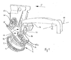
- Figur 1:
- in einer perspektivischen, überwiegend seitlichen Darstellung einen unterhalb eines Längslenkers angeordneten Achslift,
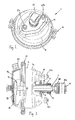
- Figur 2:
- eine perspektivische Darstellung des Betätigungselements des in
Figur 1 dargestellten Achslifts, - Figur 3:
- eine seitliche, teilweise geschnittene Ansicht des Betätigungselements aus
Figur 2 , - Figur 4:
- eine Vollschnittdarstellung durch einen Nachrüstsatz und weitere Bauteile eines Achsliftbetätigungselements, gemäß der Darstellung in
Figur 3 , - Figur 5:
- eine Draufsicht auf das Betätigungselement, wobei zur Veranschaulichung einige Elemente nicht dargestellt sind,
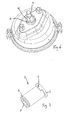
- Figur 6:
- eine perspektivische Ansicht des Betätigungselements, wobei zur Veranschaulichung u. a. das Führungselement nicht dargestellt ist und
- Figur 7:
- eine perspektivische Ansicht eines Führungselements.
- In
Fig. 1 sind Teile einer luftgefederten Fahrzeugachse mit einem im Bereich eines chassisfesten Lagerbolzens 20 vorgesehenen Achslift dargestellt, wobei von dem die Fahrzeugräder tragenden Achskörper 21 nur die Mittellinie eingezeichnet ist. Der Achskörper 21 ist mit Längslenkern 22 auf beiden Seiten des Fahrzeugs fest verbunden. Die Verbindung des Achskörpers 21 mit den Längslenkern 22 erfolgt üblicherweise über Schraubbügel. Die Längslenker 22 sind an ihren in Fahrtrichtung F vorn liegenden Enden mittels eines ein Schwenkgelenk bildenden Lagerbolzens 20 an einer Konsole 23 schwenkbar, die ihrerseits von unten gegen das Fahrzeugchassis verschweißt ist. Am gegenüberliegenden Ende sind die Längslenker 22 über eine in den Figuren nicht dargestellte Luftfeder gegenüber dem Fahrzeugrahmen federnd abgestützt. Zwischen dem Fahrzeugrahmen und den Längslenkern 21 kann sich zudem ein Stoßdämpfer befinden. - Um die in
Fig. 1 in ihrer abgesenkten Fahrstellung dargestellte Luftfederachse, falls diese für den Fahrbetrieb nicht benötigt wird, in ihre angehobene Stellung zu heben, ist am unteren Ende der Konsole 23 ein Achslift vorgesehen. Der Achslift besteht aus einer U-förmigen Aufnahme 24 zur Befestigung des Betätigungselements 1. Die Aufnahme 24 ist um die Achse des Lagerbolzens 20 schwenkbar in verschiedenen Schwenkstellungen gemäß einem Bohrungsregister 25 festlegbar. - Bei dem in den Figuren des Ausführungsbeispiels dargestellten Betätigungselement 1 handelt es sich um einen Membranzylinder. Dieser ist unterhalb der Aufnahme 24 über Schraubverbindungen 15 a, 15 b an einer ebenen Trägerplatte 26 der Aufnahme 24 festgelegt. Die Trägerplatte 26 weist eine Öffnung auf, durch welche eine Betätigungsstange 2 des Betätigungselements 1 hindurchragt. Die Betätigungsstange 2 ist an ihrem vorderen Ende mit einem rollenförmigen Kontaktelement 16 zur Übertragung der zum Anheben des Längslenkers 22 und damit der Achse 21 erforderlichen Betätigungskräfte versehen.
- Die Übertragung der Betätigungskräfte erfolgt jedoch nicht direkt von der Rolle 16 auf den Längslenker 22, sondern über einen zum Achslift gehörenden Schwenkarm 27, der ebenfalls um die Achse des Lagerbolzens 20 schwenkbar ist. An seinem freien Ende weist der Schwenkarm 27 ein Pufferelement 28 auf, mit welchem sich der Schwenkarm 27 von unten gegen die Unterseite des Längslenkers 22 legen kann. An seiner Unterseite weist der Schwenkarm 27, dem Pufferelement 28 abgewandt, eine Abrollfläche 29 für die Rolle 16 des Betätigungselements 1 auf. Diese Abrollfläche 29 weist die Kontur einer Evolvente auf, so dass die Betätigungsstange 2 unabhängig von der Schwenkstellung des Längslenkers 22 stets senkrecht auf der Abrollfläche 29 steht. Hierdurch wird vermieden, dass Querkräfte auf die Betätigungsstange 2 wirken.
- Zur Vermeidung unerwünschter Querkräfte ist die Betätigungsstange 2 entlang des Führungselements 3 zudem verdrehsicher geführt, was nachfolgend anhand der
Fign. 2 bis 7 erläutert werden wird. - In
Fig. 2 ist das Betätigungselement 1 in einer perspektivischen Ansicht dargestellt. Zu erkennen sind die beiden Verschraubungen 15 a, 15 b, über welche das Betätigungselement 1 an der Aufnahme 24 des Achslifts befestigt wird. Das Betätigungselement 1 weist ein aus zwei Hälften 4 a, 4 b zusammengesetztes Gehäuse 4 auf, die über eine Spannringanordnung 17, bestehend aus zwei Spannringhälften sowie zwei zum Umfang des Gehäuses tangential ausgerichteten Spannschrauben, gegeneinander festgelegt sind. Zu erkennen ist ferner die als Kontaktelement dienende, frei drehbar gelagerte Rolle 16. - Anhand
Fig. 3 werden nachfolgend Einzelheiten des Betätigungselements 1 erläutert. Zu erkennen ist, dass die Betätigungsstange 2 an ihrem freien, aus dem Gehäuse 4 ragenden Ende ein Kontaktelement in Form einer metallischen Rolle 16 aufweist. Über diese Rolle 16 werden die Betätigungskräfte von der Betätigungsstange 2 auf den Längslenker übertragen. Die Rolle 16 ist von zylindrischer Form und über einen Lagerbolzen 16a frei drehbar innerhalb einer U-förmigen, den Lagerbolzen 16b aufnehmenden Haltegabel 16b gelagert. Die Haltegabel 16b ist auf einen am freien Ende der Betätigungsstange 2 vorgesehenen Gewindeabschnitt aufgeschraubt, wobei die Drehstellung der Gabel 16b über eine Konturmutter 44 festgelegt ist. - An ihrem gehäuseinneren Ende ist die Betätigungsstange 2 mit einem flachen Druckteller 18 versehen, der über eine den Innenraum des Gehäuses 4 in zwei Kammern unterteilende Membran 19 mit einem Druck beaufschlagbar ist. Zur Druckbeaufschlagung des Drucktellers 18 ist am Gehäuse 4 eine Öffnung 41 vorgesehen, die der Druckluftzu- bzw. - abfuhr dient. Bei Druckluftzufuhr wird die Druckplatte 18 mit einem Druck beaufschlagt und entgegen der Kraft der auf der anderen Seite des Drucktellers 18 angeordneten Rückstellfeder 42 bewegt. Dabei wird die Betätigungsstange 2 axial aus dem Gehäuse 4 herausgefahren. Die Verfahrbewegung erfolgt in Axialrichtung der Betätigungsstange 2, wobei diese Bewegung von einem beim Ausführungsbeispiel als Kunststoffbuchse ausgebildeten Führungselement 3 geführt wird. Bei dem Führungselement 3 handelt es sich um eine Kunststoff-Buchse, die eine schmiermittelfreie Führung bzw. Gleitlagerung der Betätigungsstange 2 erlaubt. Zum Schutz vor Verunreinigungen ist zwischen der Betätigungsstange 2 und einer das Führungselement 3 aufnehmenden, metallischen Buchse 10 ein Faltenbalg 14 vorgesehen, der das Gehäuseinnere staub- bzw. schmutzdicht abschirmt.
- Die Buchse 10 ist mit einer Flanschplatte 12 baueinheitlich, z. B. durch Schweißen, verbunden. Gemeinsam mit der Buchse 10 und der Flanschplatte 12 können als Nachrüstsatz das Führungselement 3, der Faltenbalg 14 und der Sicherungsring 35 als einheitlicher Bausatz an dem Gehäuse 4 des Betätigungselements 1 festgelegt werden, wobei sich über die parallel zum Gehäuseboden verlaufende Flanschplatte 12 gleichzeitig eine mechanische Verstärkung des Gehäusebodens ergibt. Hierzu werden die auf die Betätigungsstange 2 aufgeschraubten Bauteile 16 b und 44 entfernt und der Nachrüstsatz mit der Öffnung 5 des Führungselements 3 über die Betätigungsstange 2 geschoben und am Gehäuse 4 festgelegt. Alternativ kann die Buchse 10 auch in eine Öffnung des Bodens der Gehäusehälfte 4a eingeschweißt werden, wobei dann auf die bei der Nachrüstlösung vorgesehene Flanschplatte 12 verzichtet werden kann. In diesem Fall ist jedoch der Austausch eines verschlissenen Führungselements 3, wie nachfolgend noch näher zu erläutern sein wird, nicht oder nur mit erhöhtem Aufwand möglich.
- Wie
Fig. 4 erkennen lässt, weist die Betätigungsstange 2 einen ersten Abschnitt A1 mit unrundem Querschnitt auf, der im Wesentlichen quadratisch ausgebildet ist, vgl. auch die perspektivische Darstellung inFig. 6 . Die Länge des quadratischen Abschnitts A1 ist so bemessen, dass über den gesamten Verfahrweg der Betätigungsstange 2 entlang des Führungselements 3 stets ein unrunder Querschnitt im Inneren des Führungselements 3 anliegt. Auch die Öffnung 5 des Führungselements 3 ist von unrunder, mehreckiger Querschnittsgeometrie, so dass die Betätigungsstange 2 und das Führungselement 3 gegeneinander gegen Verdrehen gesichert sind, vgl.Fig. 5 . Beim Ausführungsbeispiel weist die Öffnung 5 einen im Wesentlichen quadratischen Querschnitt auf. - Beim Führungselement 3 handelt es sich um eine Kunststoff-Gleitlagerbuchse, die innerhalb einer metallischen Buchse 10 verdrehsicher aufgenommen ist. Die Verdrehsicherung der Kunststoffbuchse 3 gegenüber der äußeren Buchse 10 kann entweder durch Einpressen des Führungselements 3 in das Innere der Buchse 10 erfolgen, oder, wie beim Ausführungsbeispiel, durch miteinander korrespondierende Sicherungselemente 7, 11 z.B. in Form von Vor- oder Rücksprüngen realisiert sein.
- Die Funktionsweise der Sicherungselemente 7, 11 lässt sich am besten den
Fign. 6 und 7 entnehmen. InFig. 6 dargestellt ist eine perspektivische Ansicht des Betätigungselements, wobei u.a. das zwischen dem quadratischen Abschnitt der Betätigungsstange 2 und der Buchse 10 angeordnete Führungselement 3 und der Balg 14 zur Veranschaulichung nicht dargestellt sind. Zu erkennen ist, dass die Buchse 10 stirnseitig mit nutförmigen Sicherungselementen 11 versehen ist, die einander um 180° über den Umfang der Buchse 10 versetzt gegenüberliegend angeordnet sind. Alternativ könnten die Sicherungselemente 11 auch am Innenumfang der Buchse 10 angeordnet sein. - Die Darstellung in
Fig. 7 lässt die korrespondierenden Sicherungselemente 7 der Buchse 3 erkennen. Diese werden von am Mantel des Führungselements 3 ausgebildeten Vorsprüngen 7 gebildet, die nach Art einer Feder-Nut-Verbindung in die Aussparungen 11 der Buchse 10 eingreifen und so für eine Verdrehsicherung des Führungselements 3 innerhalb der Buchse 10 sorgen. - Die axiale Sicherung des Führungselements 3 erfolgt über dessen Flanschbereich 8, der sich von außen her an einer Stirnseite der Buchse 10 abstützt. In der anderen Richtung erfolgt die Axialsicherung des Führungselements 3 über einen Sicherungsring 35, der nach dem Einschieben des Führungselements 3 in die Buchse 10 in einer Außenumfangsnut 9 des Führungselements 3 an dessen dem Flanschbereich 8 gegenüberliegenden Ende verrastet wird, vgl.
Fig. 4 . Auf diese Weise ist das Führungselement 3 in axialer Richtung innerhalb der Buchse 10 lagegesichert. - Aufgrund dieser Axialsicherung kann ein verschlissenes Führungselement 3 von außerhalb des Gehäuses 4 nicht aus der Buchse 10 herausgezogen und gegen eine neue Buchse ersetzt werden. Auch ist es nicht oder nur unter Einsatz von in der Praxis kaum zur Verfügung stehendem Spezialwerkzeug möglich, von gehäuseinnen her an den Sicherungsring 35 zu gelangen und auf diese Weise die Axialsicherung des Führungselements 3 zu lösen. Denn die im Inneren des Gehäuses 4 angeordnete, die beiden Gehäusehälften 4a, 4b mit einer erheblichen Vorspannkraft beaufschlagende Feder 42 erschwert das Öffnen des Gehäuses 4. Aufgrund dieser Federkraft ist für den Monteur nicht ohne Verletzungsrisiko möglich, die Spannringanordnung 17 und mit dieser die Hälften 4a, 4b des Gehäuses 4 mit herkömmlichen Werkzeugen voneinander zu lösen. Üblicherweise ist das Gehäuse 4 daher sogar mit einem Warnhinweis versehen, der den Monteur vor dem Lösen der Spannringanordnung 17 warnt. Ebenso wenig ist es möglich, die Hälften 4a, 4b des Gehäuses 4 mit Standardwerkzeugen zusammenzusetzen. Hierzu sind Spezialwerkzeuge bzw. Spannvorrichtungen erforderlich, die in der Praxis jedoch nicht zur Verfügung stehen. Damit ist der Austausch eines verschlissenen Führungselements 3 nicht möglich, so dass das Betätigungselement 1 insgesamt gegen ein Neuteil zu ersetzten ist.
- Der Austausch eines verschlissenen Führungselements 3 wird erst aufgrund des Nachrüstsatzes bzw. der Flanschplatte 12 mit herkömmlichen Werkzeugen möglich. Die Bauteile des Nachrüstsatzes sind nicht federbelastet, weshalb sich die Flanschplatte 12 und mit dieser die Buchse 10, das Führungselement 3 und der die Axialsicherung bewirkende Ring 35 ohne weiteres vom Gehäuse 4 lösen lassen. Nach dem Lösen der Flanschplatte 12 ist der Zugriff auf die innere Axialsicherung des Führungselements 3 frei, so dass dieses ersetzt werden kann. Auch können die Flanschplatte 12, die Buchse 10, das Führungselement 3, der Ring 35 und ggf. ein Faltenbalg 14 als bauliche Einheit gegen eine neue Einheit ersetzt werden.
- Einzelheiten der Anordnung des Faltenbalgs lassen sich der Darstellung in
Fig. 4 entnehmen. Danach ist der Faltenbalg 14 zwischen einer am Außenumfang der Buchse 10 vorgesehenen Nut und einem aus dem Gehäuse ragenden Abschnitt A2 der Betätigungsstange 2 mit rundem Querschnitt vorgesehen, um das Innere des Gehäuses 4 des Betätigungselements 1 vor Verunreinigungen, etwa Staub, Schmutzwasser oder Ähnlichem zu schützen. Der Abschnitt A2 der Betätigungsstange ist von rundem Querschnitt. Das eine Ende 14 a des Faltenbalgs 14 ist in einer Außenumfangsnut der Buchse 10 aufgenommen, wohingegen das andere Ende 14 b auf dem zylindrischen Umfang der Betätigungsstange 2 im Bereich A2 zwischen einer eine erste axiale Anschlagfläche bereitstellenden Mutter 44 und einer im Übergang vom quadratischen auf den runden Querschnitt sich ergebenden zweiten Anschlagfläche 45 gesichert ist. Es können herkömmliche Bälge 14 mit ringförmigen Endbereichen 14a, 14b verwendet werden. -
- 1
- Betätigungselement
- 2
- Betätigungsstange
- 3
- Führungselement
- 4
- Gehäuse
- 4 a
- Gehäusehälfte
- 4 b
- Gehäusehälfte
- 5
- Öffnung
- 6
- Gehäuseöffnung
- 7
- Sicherungselement
- 8
- Flansch
- 9
- Nut
- 10
- Buchse
- 11
- Sicherungselement
- 12
- Flanschplatte
- 13
- Sicherungsring
- 14
- Faltenbalg
- 14 a
- Faltenbalgende
- 14 b
- Faltenbalgende
- 15 a
- Verschraubung
- 15 b
- Verschraubung
- 16
- Kontaktelement, Rolle
- 16a
- Lagerbolzen
- 16b
- Haltegabel
- 17
- Spannringanordnung
- 18
- Druckteller
- 19
- Membran
- 20
- Lagerbolzen
- 21
- Achskörper
- 22
- Längslenker
- 23
- Konsole
- 24
- Aufnahme
- 25
- Lochregister
- 26
- Trägerplatte
- 27
- Schwenkarm
- 28
- Pufferelement
- 29
- Abrollfläche
- 35
- Sicherungsring
- 36 a
- Montagebohrung
- 36 b
- Montagebohrung
- 41
- Öffnung
- 42
- Rückstellfeder
- 44
- Mutter
- A1
- Abschnitt mit unrundem Querschnitt
- A2
- Abschnitt mit rundem Querschnitt
Claims (15)
- Betätigungselement für Achslifte luftgefederter Fahrzeugachsen mit einer entlang eines Führungselements (3) verfahrbaren Betätigungsstange (2),
dadurch gekennzeichnet,
dass die Betätigungsstange (2) innerhalb des Führungselements (3) verdrehsicher geführt ist. - Betätigungselement nach Anspruch 1, dadurch gekennzeichnet, dass die Betätigungsstange (2) einen im Querschnitt unrunden Abschnitt (A1) aufweist, der innerhalb einer Öffnung (5) des Führungselements (3) verdrehsicher geführt ist.
- Betätigungselement nach Anspruch 2, dadurch gekennzeichnet, dass der Abschnitt (A1) und die Öffnung (5) einen mehreckigen Querschnitt aufweisen.
- Betätigungselement nach einem der vorhergehenden Ansprüche, dadurch gekennzeichnet, dass das Führungselement (3) innerhalb einer gehäusefesten Buchse (10) verdrehsicher gegenüber einem Gehäuse (4) angeordnet ist.
- Betätigungselement nach einem der Ansprüche 1 bis 4, dadurch gekennzeichnet, dass das Führungselement (3) an seinem der Verdrehsicherung abgewandten Ende eine Nut (9) zur Aufnahme eines Sicherungsrings (13) aufweist.
- Betätigungselement nach einem der vorhergehenden Ansprüche, gekennzeichnet durch einen das Innere des Gehäuses (4) abdichtenden Faltenbalg (14).
- Betätigungselement nach Anspruch 6, dadurch gekennzeichnet, dass das eine Ende (14b) des Faltenbalgs (14) an der Buchse (10) und das andere Ende (14b) an einem runden Längsabschnitt (A2)der Betätigungsstange (2) festgelegt ist.
- Betätigungselement nach einem der vorangehenden Ansprüche, dadurch gekennzeichnet, dass eine Flanschplatte (12) über Verschraubungen (15a, 15b) zur Montage des Betätigungselements am Achslift an dem Gehäuse (4) festgelegt ist.
- Betätigungselement nach einem der vorhergehenden Ansprüche, gekennzeichnet durch eine am freien Ende der Betätigungsstange (2) angeordnete frei drehbar gelagerte Rolle.
- Nachrüstsatz für Achsliftbetätigungselemente, mit einem innerhalb einer Buchse (10) angeordneten Führungselement (3) zur Führung einer Betätigungsstange,
dadurch gekennzeichnet,
dass die Buchse (10) mit einer am Gehäuse des Achsliftbetätigungselements festlegbaren Flanschplatte (12) verbunden ist. - Nachrüstsatz nach Anspruch 10, dadurch gekennzeichnet, dass das Führungselement (3) eine Öffnung (5) zur verdrehsicheren Führung der Betätigungsstange aufweist.
- Nachrüstsatz nach einem der Ansprüche 4 bis 11, dadurch gekennzeichnet, dass das Führungselement (3) und die Buchse (10) über miteinander korrespondierende Sicherungselemente (7, 11) gegeneinander gegen Verdrehen gesichert sind.
- Nachrüstsatz nach Anspruch 12, dadurch gekennzeichnet, dass ein Sicherungselement (7) des Führungselements (3) ein Vorsprung an dessen Mantel ist, und dass das Sicherungselement (11) der Buchse (10) eine an deren Innenfläche und/oder Stirnfläche ausgebildete Ausnehmung ist.
- Nachrüstsatz nach einem der Ansprüche 12 und/oder 13, dadurch gekennzeichnet, dass das Führungselement (3) einen Flanschabschnitt (8) aufweist, der gegen eine Stirnseite der Buchse (10) anliegt.
- Nachrüstsatz nach einem der vorangehenden Ansprüche, dadurch gekennzeichnet, dass das Führungselement (3) an seinem der Verdrehsicherung abgewandten Ende eine Nut (9) zur Aufnahme eines Sicherungsrings (13) aufweist.
Applications Claiming Priority (1)
| Application Number | Priority Date | Filing Date | Title |
|---|---|---|---|
| DE102007045849A DE102007045849A1 (de) | 2007-09-26 | 2007-09-26 | Betätigungselement für Achslifte und Nachrüstsatz für Achsliftbetätigungselemente |
Publications (3)
| Publication Number | Publication Date |
|---|---|
| EP2042412A2 true EP2042412A2 (de) | 2009-04-01 |
| EP2042412A3 EP2042412A3 (de) | 2009-09-30 |
| EP2042412B1 EP2042412B1 (de) | 2011-08-31 |
Family
ID=40040077
Family Applications (1)
| Application Number | Title | Priority Date | Filing Date |
|---|---|---|---|
| EP08105212A Active EP2042412B1 (de) | 2007-09-26 | 2008-09-03 | Betätigungselement für Achslifte und Nachrüstsatz für Achsliftbetätigungselemente |
Country Status (4)
| Country | Link |
|---|---|
| EP (1) | EP2042412B1 (de) |
| AT (1) | ATE522432T1 (de) |
| DE (1) | DE102007045849A1 (de) |
| ES (1) | ES2369309T3 (de) |
Cited By (3)
| Publication number | Priority date | Publication date | Assignee | Title |
|---|---|---|---|---|
| EP2915727A4 (de) * | 2013-02-11 | 2016-10-05 | Accesorios Y Elevadores Valencia S L | Vorrichtung zum anheben einer achse eines fahrzeugs |
| WO2016206864A1 (de) * | 2015-06-22 | 2016-12-29 | Zf Friedrichshafen Ag | Anordnung zur abdichtung eines aktuators und adapterring zur abdichtung |
| US11472247B2 (en) * | 2019-10-01 | 2022-10-18 | Firestone Industrial Products Company, Llc | Mounting bracket assemblies as well as suspension assemblies, kits and methods including same |
Families Citing this family (2)
| Publication number | Priority date | Publication date | Assignee | Title |
|---|---|---|---|---|
| DE102011001431B4 (de) | 2011-03-21 | 2022-09-29 | Bpw Bergische Achsen Kg | Achslift für eine Fahrzeugachse |
| DE102012006676A1 (de) * | 2012-03-31 | 2013-04-04 | Daimler Ag | Verfahren zum Montieren einer Fahrzeug-Achseinheit |
Citations (3)
| Publication number | Priority date | Publication date | Assignee | Title |
|---|---|---|---|---|
| US3208803A (en) | 1962-05-09 | 1965-09-28 | W E Hennells Co Inc | Guide bearing and rod seal |
| EP0591614A1 (de) | 1992-07-24 | 1994-04-13 | Festo KG | Kolben-Zylinder-Aggregat |
| EP0961726A1 (de) | 1997-02-28 | 1999-12-08 | BPW Bergische Achsen Kommanditgesellschaft | Achslift für luftgefederte fahrzeugachsen |
Family Cites Families (11)
| Publication number | Priority date | Publication date | Assignee | Title |
|---|---|---|---|---|
| DE7421927U (de) * | 1974-10-03 | Heller H | Zylinder mit gegen Verdrehung gesicherter Kolbenstange | |
| US3888602A (en) * | 1974-06-05 | 1975-06-10 | United Aircraft Corp | Stress restraining ring for compressor rotors |
| DE8115074U1 (de) * | 1981-05-21 | 1983-10-27 | Festo-Maschinenfabrik Gottlieb Stoll, 7300 Esslingen | "Arbeitszylinder mit Verdrehsicherung" |
| DE3807889A1 (de) * | 1988-03-10 | 1989-09-21 | Festo Kg | Druckmittelbetaetigbare schlittenartige vorschubeinrichtung |
| FR2649045A1 (fr) * | 1989-06-28 | 1991-01-04 | Essieux Ste Ardennaise | Train de roulement relevable |
| FR2665490B1 (fr) * | 1990-07-31 | 1994-03-25 | Lohr Industrie Sa | Ensemble de manóoeuvre a soufflet. |
| DE9315502U1 (de) * | 1993-10-13 | 1993-12-09 | INA Wälzlager Schaeffler KG, 91074 Herzogenaurach | Pedal- und Geberzylindergestaltung |
| DE20305231U1 (de) * | 2003-04-01 | 2003-06-12 | FESTO AG & Co., 73734 Esslingen | Fluidbetätigter Arbeitszylinder |
| DE20317350U1 (de) * | 2003-11-11 | 2004-02-12 | Trenkamp & Gehle Gmbh | Achsanhebevorrichtung für Nutzfahrzeuge |
| EP1661739B1 (de) * | 2004-11-26 | 2011-05-11 | Agueda Losada Alvarez | Achslift für luftgefederte Fahrzeugachsen |
| DE102006001839B4 (de) * | 2006-01-13 | 2011-03-17 | Saf-Holland Gmbh | Achshebevorrichtung für ein Fahrzeug |
-
2007
- 2007-09-26 DE DE102007045849A patent/DE102007045849A1/de not_active Withdrawn
-
2008
- 2008-09-03 EP EP08105212A patent/EP2042412B1/de active Active
- 2008-09-03 AT AT08105212T patent/ATE522432T1/de active
- 2008-09-03 ES ES08105212T patent/ES2369309T3/es active Active
Patent Citations (3)
| Publication number | Priority date | Publication date | Assignee | Title |
|---|---|---|---|---|
| US3208803A (en) | 1962-05-09 | 1965-09-28 | W E Hennells Co Inc | Guide bearing and rod seal |
| EP0591614A1 (de) | 1992-07-24 | 1994-04-13 | Festo KG | Kolben-Zylinder-Aggregat |
| EP0961726A1 (de) | 1997-02-28 | 1999-12-08 | BPW Bergische Achsen Kommanditgesellschaft | Achslift für luftgefederte fahrzeugachsen |
Cited By (3)
| Publication number | Priority date | Publication date | Assignee | Title |
|---|---|---|---|---|
| EP2915727A4 (de) * | 2013-02-11 | 2016-10-05 | Accesorios Y Elevadores Valencia S L | Vorrichtung zum anheben einer achse eines fahrzeugs |
| WO2016206864A1 (de) * | 2015-06-22 | 2016-12-29 | Zf Friedrichshafen Ag | Anordnung zur abdichtung eines aktuators und adapterring zur abdichtung |
| US11472247B2 (en) * | 2019-10-01 | 2022-10-18 | Firestone Industrial Products Company, Llc | Mounting bracket assemblies as well as suspension assemblies, kits and methods including same |
Also Published As
| Publication number | Publication date |
|---|---|
| DE102007045849A1 (de) | 2009-04-02 |
| EP2042412B1 (de) | 2011-08-31 |
| ES2369309T3 (es) | 2011-11-29 |
| ATE522432T1 (de) | 2011-09-15 |
| EP2042412A3 (de) | 2009-09-30 |
Similar Documents
| Publication | Publication Date | Title |
|---|---|---|
| EP0141093B1 (de) | Radaufhängung für lenkbare Vorderräder von Kraftfahrzeugen | |
| DE102018201670B4 (de) | Einzelradaufhängungsvorrichtung mit aktiver Spursteuerung eines Hinterrads eines Kraftfahrzeugs | |
| EP2060416B1 (de) | Verstellvorrichtung für Radaufhängungen | |
| DE2912533A1 (de) | Achsfederung | |
| EP2207690B1 (de) | Einzelradaufhängung | |
| DE3403466C2 (de) | ||
| DE102012209690B4 (de) | Lenkanordnung | |
| EP2834093B1 (de) | Schwerlastanhänger mit macpherson-einzelradaufhängung | |
| EP2042412B1 (de) | Betätigungselement für Achslifte und Nachrüstsatz für Achsliftbetätigungselemente | |
| EP4699828A1 (de) | Lenkbare einzelradaufhängung mit zusätzlichem träger | |
| DE102009040163B4 (de) | Achsführungslager zur Ankopplung einer Hinterachse an einen Fahrzeugaufbau | |
| EP1565370B1 (de) | Schwenklager sowie mit einem solchen ausgestattete lenkachse | |
| EP0961726B1 (de) | Achslift für luftgefederte fahrzeugachsen | |
| EP1013961B1 (de) | Gelenklager, insbesondere Federaugenlager | |
| EP2396183B1 (de) | Radaufhängung für kraftfahrzeuge mit einem dem radträger zugeordneten stellglied zur einstellung eines spur- und/oder sturzwinkels | |
| DE10348645A1 (de) | Kraftfahrzeug | |
| DE102016003885A1 (de) | Radaufhängung für einen Mobilkran | |
| DE102011081543A1 (de) | Flach bauende Radaufhängung mit Strebe, Wippe und quer umgelenktem Dämpferelement | |
| DE102010022762A1 (de) | Kraftfahrzeugachse mit Panhardstab | |
| DE2161058A1 (de) | Stabilisatoranordnung fuer achsen an gezogenen strassenfahrzeugen | |
| EP1609697B1 (de) | Lenkachse | |
| EP2921379B1 (de) | Schwertransportfahrzeug zum Transportieren einer Last über eine Bodenfläche | |
| DE102016111990B4 (de) | Lenkersystem | |
| DE102012014001A1 (de) | Knickgelenkfahrzeug und Knickgelenkanordnung für ein solches Fahrzeug | |
| DE102012102848A1 (de) | Achslenker |
Legal Events
| Date | Code | Title | Description |
|---|---|---|---|
| PUAI | Public reference made under article 153(3) epc to a published international application that has entered the european phase |
Free format text: ORIGINAL CODE: 0009012 |
|
| AK | Designated contracting states |
Kind code of ref document: A2 Designated state(s): AT BE BG CH CY CZ DE DK EE ES FI FR GB GR HR HU IE IS IT LI LT LU LV MC MT NL NO PL PT RO SE SI SK TR |
|
| AX | Request for extension of the european patent |
Extension state: AL BA MK RS |
|
| PUAL | Search report despatched |
Free format text: ORIGINAL CODE: 0009013 |
|
| AK | Designated contracting states |
Kind code of ref document: A3 Designated state(s): AT BE BG CH CY CZ DE DK EE ES FI FR GB GR HR HU IE IS IT LI LT LU LV MC MT NL NO PL PT RO SE SI SK TR |
|
| AX | Request for extension of the european patent |
Extension state: AL BA MK RS |
|
| 17P | Request for examination filed |
Effective date: 20100326 |
|
| 17Q | First examination report despatched |
Effective date: 20100503 |
|
| AKX | Designation fees paid |
Designated state(s): AT BE BG CH CY CZ DE DK EE ES FI FR GB GR HR HU IE IS IT LI LT LU LV MC MT NL NO PL PT RO SE SI SK TR |
|
| GRAP | Despatch of communication of intention to grant a patent |
Free format text: ORIGINAL CODE: EPIDOSNIGR1 |
|
| GRAS | Grant fee paid |
Free format text: ORIGINAL CODE: EPIDOSNIGR3 |
|
| GRAA | (expected) grant |
Free format text: ORIGINAL CODE: 0009210 |
|
| AK | Designated contracting states |
Kind code of ref document: B1 Designated state(s): AT BE BG CH CY CZ DE DK EE ES FI FR GB GR HR HU IE IS IT LI LT LU LV MC MT NL NO PL PT RO SE SI SK TR |
|
| REG | Reference to a national code |
Ref country code: CH Ref legal event code: EP Ref country code: GB Ref legal event code: FG4D Free format text: NOT ENGLISH |
|
| REG | Reference to a national code |
Ref country code: IE Ref legal event code: FG4D Free format text: LANGUAGE OF EP DOCUMENT: GERMAN |
|
| REG | Reference to a national code |
Ref country code: DE Ref legal event code: R096 Ref document number: 502008004659 Country of ref document: DE Effective date: 20111103 |
|
| REG | Reference to a national code |
Ref country code: ES Ref legal event code: FG2A Ref document number: 2369309 Country of ref document: ES Kind code of ref document: T3 Effective date: 20111129 |
|
| REG | Reference to a national code |
Ref country code: NL Ref legal event code: VDEP Effective date: 20110831 |
|
| LTIE | Lt: invalidation of european patent or patent extension |
Effective date: 20110831 |
|
| PG25 | Lapsed in a contracting state [announced via postgrant information from national office to epo] |
Ref country code: HR Free format text: LAPSE BECAUSE OF FAILURE TO SUBMIT A TRANSLATION OF THE DESCRIPTION OR TO PAY THE FEE WITHIN THE PRESCRIBED TIME-LIMIT Effective date: 20110831 Ref country code: SE Free format text: LAPSE BECAUSE OF FAILURE TO SUBMIT A TRANSLATION OF THE DESCRIPTION OR TO PAY THE FEE WITHIN THE PRESCRIBED TIME-LIMIT Effective date: 20110831 Ref country code: NL Free format text: LAPSE BECAUSE OF FAILURE TO SUBMIT A TRANSLATION OF THE DESCRIPTION OR TO PAY THE FEE WITHIN THE PRESCRIBED TIME-LIMIT Effective date: 20110831 Ref country code: LT Free format text: LAPSE BECAUSE OF FAILURE TO SUBMIT A TRANSLATION OF THE DESCRIPTION OR TO PAY THE FEE WITHIN THE PRESCRIBED TIME-LIMIT Effective date: 20110831 Ref country code: IS Free format text: LAPSE BECAUSE OF FAILURE TO SUBMIT A TRANSLATION OF THE DESCRIPTION OR TO PAY THE FEE WITHIN THE PRESCRIBED TIME-LIMIT Effective date: 20111231 Ref country code: NO Free format text: LAPSE BECAUSE OF FAILURE TO SUBMIT A TRANSLATION OF THE DESCRIPTION OR TO PAY THE FEE WITHIN THE PRESCRIBED TIME-LIMIT Effective date: 20111130 Ref country code: FI Free format text: LAPSE BECAUSE OF FAILURE TO SUBMIT A TRANSLATION OF THE DESCRIPTION OR TO PAY THE FEE WITHIN THE PRESCRIBED TIME-LIMIT Effective date: 20110831 |
|
| PG25 | Lapsed in a contracting state [announced via postgrant information from national office to epo] |
Ref country code: LV Free format text: LAPSE BECAUSE OF FAILURE TO SUBMIT A TRANSLATION OF THE DESCRIPTION OR TO PAY THE FEE WITHIN THE PRESCRIBED TIME-LIMIT Effective date: 20110831 Ref country code: CY Free format text: LAPSE BECAUSE OF FAILURE TO SUBMIT A TRANSLATION OF THE DESCRIPTION OR TO PAY THE FEE WITHIN THE PRESCRIBED TIME-LIMIT Effective date: 20110831 Ref country code: SI Free format text: LAPSE BECAUSE OF FAILURE TO SUBMIT A TRANSLATION OF THE DESCRIPTION OR TO PAY THE FEE WITHIN THE PRESCRIBED TIME-LIMIT Effective date: 20110831 Ref country code: GR Free format text: LAPSE BECAUSE OF FAILURE TO SUBMIT A TRANSLATION OF THE DESCRIPTION OR TO PAY THE FEE WITHIN THE PRESCRIBED TIME-LIMIT Effective date: 20111201 |
|
| REG | Reference to a national code |
Ref country code: IE Ref legal event code: FD4D |
|
| BERE | Be: lapsed |
Owner name: BPW BERGISCHE ACHSEN K.G. Effective date: 20110930 |
|
| PG25 | Lapsed in a contracting state [announced via postgrant information from national office to epo] |
Ref country code: CZ Free format text: LAPSE BECAUSE OF FAILURE TO SUBMIT A TRANSLATION OF THE DESCRIPTION OR TO PAY THE FEE WITHIN THE PRESCRIBED TIME-LIMIT Effective date: 20110831 Ref country code: IE Free format text: LAPSE BECAUSE OF FAILURE TO SUBMIT A TRANSLATION OF THE DESCRIPTION OR TO PAY THE FEE WITHIN THE PRESCRIBED TIME-LIMIT Effective date: 20110831 Ref country code: MC Free format text: LAPSE BECAUSE OF NON-PAYMENT OF DUE FEES Effective date: 20110930 Ref country code: SK Free format text: LAPSE BECAUSE OF FAILURE TO SUBMIT A TRANSLATION OF THE DESCRIPTION OR TO PAY THE FEE WITHIN THE PRESCRIBED TIME-LIMIT Effective date: 20110831 |
|
| PG25 | Lapsed in a contracting state [announced via postgrant information from national office to epo] |
Ref country code: EE Free format text: LAPSE BECAUSE OF FAILURE TO SUBMIT A TRANSLATION OF THE DESCRIPTION OR TO PAY THE FEE WITHIN THE PRESCRIBED TIME-LIMIT Effective date: 20110831 Ref country code: RO Free format text: LAPSE BECAUSE OF FAILURE TO SUBMIT A TRANSLATION OF THE DESCRIPTION OR TO PAY THE FEE WITHIN THE PRESCRIBED TIME-LIMIT Effective date: 20110831 Ref country code: PT Free format text: LAPSE BECAUSE OF FAILURE TO SUBMIT A TRANSLATION OF THE DESCRIPTION OR TO PAY THE FEE WITHIN THE PRESCRIBED TIME-LIMIT Effective date: 20120102 Ref country code: PL Free format text: LAPSE BECAUSE OF FAILURE TO SUBMIT A TRANSLATION OF THE DESCRIPTION OR TO PAY THE FEE WITHIN THE PRESCRIBED TIME-LIMIT Effective date: 20110831 |
|
| PG25 | Lapsed in a contracting state [announced via postgrant information from national office to epo] |
Ref country code: DK Free format text: LAPSE BECAUSE OF FAILURE TO SUBMIT A TRANSLATION OF THE DESCRIPTION OR TO PAY THE FEE WITHIN THE PRESCRIBED TIME-LIMIT Effective date: 20110831 Ref country code: BE Free format text: LAPSE BECAUSE OF NON-PAYMENT OF DUE FEES Effective date: 20110930 |
|
| PLBE | No opposition filed within time limit |
Free format text: ORIGINAL CODE: 0009261 |
|
| STAA | Information on the status of an ep patent application or granted ep patent |
Free format text: STATUS: NO OPPOSITION FILED WITHIN TIME LIMIT |
|
| 26N | No opposition filed |
Effective date: 20120601 |
|
| REG | Reference to a national code |
Ref country code: DE Ref legal event code: R097 Ref document number: 502008004659 Country of ref document: DE Effective date: 20120601 |
|
| PG25 | Lapsed in a contracting state [announced via postgrant information from national office to epo] |
Ref country code: MT Free format text: LAPSE BECAUSE OF FAILURE TO SUBMIT A TRANSLATION OF THE DESCRIPTION OR TO PAY THE FEE WITHIN THE PRESCRIBED TIME-LIMIT Effective date: 20110831 |
|
| REG | Reference to a national code |
Ref country code: CH Ref legal event code: PL |
|
| PG25 | Lapsed in a contracting state [announced via postgrant information from national office to epo] |
Ref country code: LU Free format text: LAPSE BECAUSE OF NON-PAYMENT OF DUE FEES Effective date: 20110903 |
|
| PG25 | Lapsed in a contracting state [announced via postgrant information from national office to epo] |
Ref country code: BG Free format text: LAPSE BECAUSE OF FAILURE TO SUBMIT A TRANSLATION OF THE DESCRIPTION OR TO PAY THE FEE WITHIN THE PRESCRIBED TIME-LIMIT Effective date: 20111130 |
|
| PG25 | Lapsed in a contracting state [announced via postgrant information from national office to epo] |
Ref country code: LI Free format text: LAPSE BECAUSE OF NON-PAYMENT OF DUE FEES Effective date: 20120930 Ref country code: CH Free format text: LAPSE BECAUSE OF NON-PAYMENT OF DUE FEES Effective date: 20120930 |
|
| PG25 | Lapsed in a contracting state [announced via postgrant information from national office to epo] |
Ref country code: HU Free format text: LAPSE BECAUSE OF FAILURE TO SUBMIT A TRANSLATION OF THE DESCRIPTION OR TO PAY THE FEE WITHIN THE PRESCRIBED TIME-LIMIT Effective date: 20110831 |
|
| REG | Reference to a national code |
Ref country code: AT Ref legal event code: MM01 Ref document number: 522432 Country of ref document: AT Kind code of ref document: T Effective date: 20130903 |
|
| REG | Reference to a national code |
Ref country code: DE Ref legal event code: R082 Ref document number: 502008004659 Country of ref document: DE Representative=s name: BUNGARTZ CHRISTOPHERSEN PARTNERSCHAFT MBB PATE, DE |
|
| PG25 | Lapsed in a contracting state [announced via postgrant information from national office to epo] |
Ref country code: AT Free format text: LAPSE BECAUSE OF NON-PAYMENT OF DUE FEES Effective date: 20130903 |
|
| REG | Reference to a national code |
Ref country code: FR Ref legal event code: PLFP Year of fee payment: 9 |
|
| REG | Reference to a national code |
Ref country code: FR Ref legal event code: PLFP Year of fee payment: 10 |
|
| REG | Reference to a national code |
Ref country code: FR Ref legal event code: PLFP Year of fee payment: 11 |
|
| REG | Reference to a national code |
Ref country code: DE Ref legal event code: R082 Ref document number: 502008004659 Country of ref document: DE Representative=s name: DREISS PATENTANWAELTE PARTG MBB, DE Ref country code: DE Ref legal event code: R082 Ref document number: 502008004659 Country of ref document: DE Representative=s name: JANKE SCHOLL PATENTANWAELTE PARTG MBB, DE |
|
| REG | Reference to a national code |
Ref country code: DE Ref legal event code: R082 Ref document number: 502008004659 Country of ref document: DE Representative=s name: DREISS PATENTANWAELTE PARTG MBB, DE |
|
| P01 | Opt-out of the competence of the unified patent court (upc) registered |
Effective date: 20230504 |
|
| PGFP | Annual fee paid to national office [announced via postgrant information from national office to epo] |
Ref country code: TR Payment date: 20250829 Year of fee payment: 18 |
|
| PGFP | Annual fee paid to national office [announced via postgrant information from national office to epo] |
Ref country code: GB Payment date: 20250909 Year of fee payment: 18 |
|
| PGFP | Annual fee paid to national office [announced via postgrant information from national office to epo] |
Ref country code: FR Payment date: 20250925 Year of fee payment: 18 |
|
| PGFP | Annual fee paid to national office [announced via postgrant information from national office to epo] |
Ref country code: DE Payment date: 20251118 Year of fee payment: 18 |
|
| PGFP | Annual fee paid to national office [announced via postgrant information from national office to epo] |
Ref country code: IT Payment date: 20250930 Year of fee payment: 18 |
|
| PGFP | Annual fee paid to national office [announced via postgrant information from national office to epo] |
Ref country code: ES Payment date: 20251020 Year of fee payment: 18 |