EP2042084A1 - Elektronische Vorrichtung mit biometrischer Authentifizierung - Google Patents
Elektronische Vorrichtung mit biometrischer Authentifizierung Download PDFInfo
- Publication number
- EP2042084A1 EP2042084A1 EP08011252A EP08011252A EP2042084A1 EP 2042084 A1 EP2042084 A1 EP 2042084A1 EP 08011252 A EP08011252 A EP 08011252A EP 08011252 A EP08011252 A EP 08011252A EP 2042084 A1 EP2042084 A1 EP 2042084A1
- Authority
- EP
- European Patent Office
- Prior art keywords
- finger
- electronic apparatus
- imaging camera
- light source
- opening
- Prior art date
- Legal status (The legal status is an assumption and is not a legal conclusion. Google has not performed a legal analysis and makes no representation as to the accuracy of the status listed.)
- Withdrawn
Links
Images



Classifications
-
- A—HUMAN NECESSITIES
- A61—MEDICAL OR VETERINARY SCIENCE; HYGIENE
- A61B—DIAGNOSIS; SURGERY; IDENTIFICATION
- A61B5/00—Measuring for diagnostic purposes; Identification of persons
- A61B5/0059—Measuring for diagnostic purposes; Identification of persons using light, e.g. diagnosis by transillumination, diascopy, fluorescence
-
- A—HUMAN NECESSITIES
- A61—MEDICAL OR VETERINARY SCIENCE; HYGIENE
- A61B—DIAGNOSIS; SURGERY; IDENTIFICATION
- A61B5/00—Measuring for diagnostic purposes; Identification of persons
- A61B5/48—Other medical applications
- A61B5/4887—Locating particular structures in or on the body
- A61B5/489—Blood vessels
-
- G—PHYSICS
- G06—COMPUTING OR CALCULATING; COUNTING
- G06V—IMAGE OR VIDEO RECOGNITION OR UNDERSTANDING
- G06V10/00—Arrangements for image or video recognition or understanding
- G06V10/10—Image acquisition
-
- G—PHYSICS
- G06—COMPUTING OR CALCULATING; COUNTING
- G06V—IMAGE OR VIDEO RECOGNITION OR UNDERSTANDING
- G06V40/00—Recognition of biometric, human-related or animal-related patterns in image or video data
- G06V40/10—Human or animal bodies, e.g. vehicle occupants or pedestrians; Body parts, e.g. hands
- G06V40/14—Vascular patterns
Definitions
- the present invention relates to an electronic apparatus having a biometrics authentication, in more particularly pertaining to an assembly structure or arrangement of an imaging camera for obtaining biometric information such as finger veins by scanning an image on a finger irradiated with a light source in such as a personal digital assistant.
- near infrared light that is irradiated on the finger and internally scattered in the same so as to be externally transmitted with the result that the light as externally transmitted is taken as an image of biometric information on the finger veins.
- hemoglobin in the blood appears in shadowy patterns on the taken image because it absorbs such near infrared light, which makes the finger veins relived in the image.
- the individual authentication is effected by comparing such shadowy patterns with the preliminarily registered patterns of the finger veins through a taken image.
- an imaging camera is in practical use for a device provided with a finger vein authentication function as a tow-dimensional sensor, a lens and so forth being adopted for scanning an image of the finger veins.
- the prior arts on a scanning sensor of the finger veins as an imaging camera are known from JP-A 2003-298104 and JP-A 2007-156684 .
- a conventional imaging camera for scanning the finger veins described in the above references adopts a method of converging an image of the finger into a smaller two-dimensional sensor by means of a lens, which requires the finger as an object for imaging to optically separate from the lens by an interval in order to gain a high-quality focused image thereof. It is therefore necessary to secure an interval between the finger and the lens, which cannot keep an imaging camera including a portion on which the finger is placed from becoming larger in size.
- the problem to be solved by the invention lies in efficiently mounting an imaging camera for scanning the finger veins on a small-sized personal digital assistant.
- the present invention is characterized in dividing an electronic apparatus for instance a mobile apparatus into a first structure and a second structure, mounting a lens and a two-dimensional sensor of an imaging camera on the first structure, providing an optically transparent opening through the second structure, and disposing a biometric part of an individual on the second structure opposite to the first structure so as to secure an interval between a finger and the lens large enough to scan the finger veins with higher quality.
- the invention brings an effect such as an imaging camera being efficiently mounted on the mobile apparatus of smaller size by mounting the camera thereon with the two-dimensional sensor along with the lens and the optically transparent opening to secure an interval between the lens and the biometric part respectively divided into two structures.
- a personal digital assistant provided with a function to authenticate finger veins and divided into two structural members is arranged by mounting a two-dimensional sensor and a lens in the first structural member thereof and providing a transparent opening to secure an interval between the finger and the lens as well as light sources to throw light through the finger in the second structural member thereof, wherein those structural elements are disposed therein such that the lens, two-dimensional sensor, transparent opening, and light sources function as one imaging camera for finger veins when the first and second structural members are overlapped one over another.
- Fig. 1 shows a cross-sectional view of a personal digital assistant in use for scanning a finger image according to the first embodiment of the invention.
- a structural member 1 is a structural base for the personal digital assistant and provided with an imaging camera 5 for scanning the finger image and a pivot support member 3 for a hinge mechanism.
- a structural member 2 pivots around the support member 3 disposed on the structural member 1, so that those members may be attached together as shown in Fig. 1 or detached from each other as shown in Fig. 2 .
- Light sources 4a and 4b of infrared light emission are mounted in the structural member 2 to irradiate a finger placed on the surface thereof.
- An optically transparent circular opening 6 for the infrared light is provided through the structural member 2 to scan the irradiated finger image with the imaging camera 5 mounted on the structural member 1.
- the respective light sources 4a and 4b are made of infrared light emitting diodes (LED) and provided with luminous intensity and arranged to sufficiently scan the imaging camera 5 with higher quality the finger within a scanning field of vision 12 of the camera 5.
- the imaging camera 5 essentially includes a lens 5a and a two-dimensional sensor 5b, and scans an interior image of the finger including its veins pattern 11 with the finger image within the scanning field of vision 12 converged through the lens 5a into the two-dimensional sensor 5b.
- the transparent opening 6 is provided through the structural member 2, so that the length of the opening 6 is has the same as thickness 13 of the structural member 2.
- the thickness 13 of the structural member 2 or the length of the opening is defined such that the imaging camera 5 makes an optically optimum interval with the finger so that it can take the finger interior image including its veins pattern 11 with higher quality.
- the scanning and authentication steps are taken with the structural members 1 and 2 attached together, in which no light penetrates into the camera 5 from an interstice between them and the optical axis of the imaging camera corresponds to the central axis of the cylindrical opening 6 so as to make the same axial line A-A' between them, therefore those members are disposed to each other in an optimum position to scan the finger image.
- the imaging camera may be efficiently mounted in a digital assistant by making use of its structure.
- the first embodiment shows the structural member 2 pivot around the support member of the structural member 1 with a hinge mechanism provided between those members. According to the present embodiment, a sliding mechanism is provided between those members, by which the structural member 2 moves parallelwise with regard to the structural member 1.
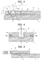
- Fig. 3 shows a cross-sectional view of a personal digital assistant according to the second embodiment scanning a finger image.
- Fig. 4 shows a trans-sectional view of the assistant taken along the optical centerline A-A' of the imaging camera. Apart from the sliding mechanism disposed between those members 1 and 2, the imaging camera 5, the light sources 4a and 4b as well as the cylindrical opening 6 hereof are the same as those of the first embodiment.
- the structural member 1 is provided with sliding rails 20a and 20b, so that the structural member 2 slides on the surface of the structural member 1 to the direction 30 as shown in Fig. 3 .
- the structural member 2 moves by way of the sliding mechanism to the left side with respect to the drawing along the direction 30 and comes to stop at the farthest left end of the structural member 1.
- the structural member 2 moves along the direction 30 and comes to stop at the farthest right end thereof, at which the optical axis of the imaging camera 5 corresponds to the central axis of the cylindrical opening 6 through the same axial line A-A', so that those members 1 and 2 are placed in an optimum position to scan the finger image for authentication.
- the present embodiment has a merit in that the imaging camera may be efficiently mounted into a personal digital assistant by making use of its structure.
- the difference between the present embodiment and the first and second embodiments respectively lies in the opening 6 hereof taking the shape of a truncated cone instead of the cylindrical shape adopted in the above embodiments.
- Fig. 6 shows a trans-sectional view of a personal digital assistant in use for scanning the finger image according to the present embodiment.
- a scanning field of vision 12 of the imaging camera 5 as shown in Fig. 6 is an area over which light irradiated from the finger and reaching the camera 5 passes when the finger veins 11 is scanned.
- the opening 6 of the structural member 2 as shown in the first embodiment does not have to be cylindrical in shape but may be a truncated cone as shown with 6a, with its shape of a circle of a diameter 8a on the upper surface of the structural member 2 and its shape of a circle of a diameter 8b on the lower surface the structural member 2.
- the volume of the transparent opening of the structural member 2 can be reduced, allowing more efficient use of the mounting area of the personal digital assistant.
- the present embodiment is the same as the first and second embodiments as mentioned above, except that a portion of the structural member 2 on which a finger is placed is concavely recessed.
- Fig. 7 shows the present embodiment, in which a trans-sectional view of the structural member 2 is taken along the B-B' line or the C-C' line centered on the light source as shown in Fig. 1 showing the cross-sectional view of a personal digital assistant according to the first embodiment.
- a recessed portion 40 is provided on the surface of the structural member 2.
- the finger ball completely closes an entrance of a hole 7 in which a light source 4 is mounted, so that light emitted from the light source 4 does not leak directly from the structural member 2, and reaches outside internally passing through the finger 10.
- the finger 10 is internally irradiated with the light source 4 in an efficient manner.
- Fig. 8 shows a trans-sectional view of the first and second structural members 1 and 2 taken along the A-A' line of Fig. 1 .
- the finger ball completely closes the entrance of the opening 6 of the structural member 2.
- the imaging camera 5 scans no incident light penetrating from the outside of the personal digital assistant, but scans only light irradiated from the finger.
- the provision of the concave configuration in a portion of the personal digital assistant on which the finger is mounted allows light emitted from the light source to internally penetrate into the finger in an efficient manner and the finger image to be scanned with high quality without incident light deriving from the outside of the digital assistant.
Landscapes
- Health & Medical Sciences (AREA)
- Life Sciences & Earth Sciences (AREA)
- Engineering & Computer Science (AREA)
- Physics & Mathematics (AREA)
- Surgery (AREA)
- Public Health (AREA)
- Biomedical Technology (AREA)
- Heart & Thoracic Surgery (AREA)
- Medical Informatics (AREA)
- Molecular Biology (AREA)
- Biophysics (AREA)
- Animal Behavior & Ethology (AREA)
- General Health & Medical Sciences (AREA)
- Pathology (AREA)
- Veterinary Medicine (AREA)
- General Physics & Mathematics (AREA)
- Multimedia (AREA)
- Theoretical Computer Science (AREA)
- Vascular Medicine (AREA)
- Image Input (AREA)
- Measurement Of The Respiration, Hearing Ability, Form, And Blood Characteristics Of Living Organisms (AREA)
- Telephone Set Structure (AREA)
Applications Claiming Priority (1)
| Application Number | Priority Date | Filing Date | Title |
|---|---|---|---|
| JP2007253019A JP2009086797A (ja) | 2007-09-28 | 2007-09-28 | 携帯端末 |
Publications (1)
| Publication Number | Publication Date |
|---|---|
| EP2042084A1 true EP2042084A1 (de) | 2009-04-01 |
Family
ID=40042936
Family Applications (1)
| Application Number | Title | Priority Date | Filing Date |
|---|---|---|---|
| EP08011252A Withdrawn EP2042084A1 (de) | 2007-09-28 | 2008-06-20 | Elektronische Vorrichtung mit biometrischer Authentifizierung |
Country Status (3)
| Country | Link |
|---|---|
| EP (1) | EP2042084A1 (de) |
| JP (1) | JP2009086797A (de) |
| CN (1) | CN101398889A (de) |
Cited By (1)
| Publication number | Priority date | Publication date | Assignee | Title |
|---|---|---|---|---|
| US20230190191A1 (en) * | 2020-08-26 | 2023-06-22 | Terumo Kabushiki Kaisha | Blood vessel visualization apparatus, blood vessel puncture system, and observation window member |
Families Citing this family (2)
| Publication number | Priority date | Publication date | Assignee | Title |
|---|---|---|---|---|
| KR101016420B1 (ko) * | 2009-05-14 | 2011-02-21 | 동국대학교 산학협력단 | 비접촉식 손가락 정맥 영상 취득 장치 및 이를 갖는 휴대용모바일 기기 |
| CN103405216A (zh) * | 2013-04-09 | 2013-11-27 | 衢州亿龙信息技术有限公司 | 浅静脉摄像装置 |
Citations (6)
| Publication number | Priority date | Publication date | Assignee | Title |
|---|---|---|---|---|
| US20020003892A1 (en) * | 2000-07-10 | 2002-01-10 | Casio Computer Co., Ltd. | Authentication system based on fingerprint and electronic device employed for the system |
| JP2003298104A (ja) | 2002-04-03 | 2003-10-17 | Rabo Sufia Kk | 光照射装置及び検知装置 |
| US20040169938A1 (en) * | 1999-11-04 | 2004-09-02 | Yoshitaka Nakamura | Portable information terminal device |
| JP2007156684A (ja) | 2005-12-02 | 2007-06-21 | Hitachi Information & Control Solutions Ltd | 指静脈認証装置を備えたパーソナルコンピュータおよび指静脈認証装置 |
| EP1821238A1 (de) * | 2006-02-20 | 2007-08-22 | Sony Ericsson Mobile Communications Japan, Inc. | Bildaufnahmevorrichtung und Biometrieauthentifizierungsvorrichtung |
| US20070223792A1 (en) * | 2006-03-24 | 2007-09-27 | C/O Sony Corporation | Portable telephone and electronic device |
Family Cites Families (5)
| Publication number | Priority date | Publication date | Assignee | Title |
|---|---|---|---|---|
| JP2003069869A (ja) * | 2001-08-27 | 2003-03-07 | Olympus Optical Co Ltd | カメラ機能を有する携帯型情報端末機器 |
| JP2003069868A (ja) * | 2001-08-27 | 2003-03-07 | Olympus Optical Co Ltd | カメラ機能を有する携帯型情報端末機器 |
| JP4291107B2 (ja) * | 2003-10-27 | 2009-07-08 | 株式会社日立製作所 | 指認証装置とその指置きガイド |
| JP2006081113A (ja) * | 2004-09-13 | 2006-03-23 | Alps Electric Co Ltd | 携帯端末装置 |
| KR100927757B1 (ko) * | 2005-06-13 | 2009-11-20 | 가부시키가이샤 히타치세이사쿠쇼 | 정보 휴대 단말 |
-
2007
- 2007-09-28 JP JP2007253019A patent/JP2009086797A/ja active Pending
-
2008
- 2008-06-16 CN CNA2008101302041A patent/CN101398889A/zh active Pending
- 2008-06-20 EP EP08011252A patent/EP2042084A1/de not_active Withdrawn
Patent Citations (6)
| Publication number | Priority date | Publication date | Assignee | Title |
|---|---|---|---|---|
| US20040169938A1 (en) * | 1999-11-04 | 2004-09-02 | Yoshitaka Nakamura | Portable information terminal device |
| US20020003892A1 (en) * | 2000-07-10 | 2002-01-10 | Casio Computer Co., Ltd. | Authentication system based on fingerprint and electronic device employed for the system |
| JP2003298104A (ja) | 2002-04-03 | 2003-10-17 | Rabo Sufia Kk | 光照射装置及び検知装置 |
| JP2007156684A (ja) | 2005-12-02 | 2007-06-21 | Hitachi Information & Control Solutions Ltd | 指静脈認証装置を備えたパーソナルコンピュータおよび指静脈認証装置 |
| EP1821238A1 (de) * | 2006-02-20 | 2007-08-22 | Sony Ericsson Mobile Communications Japan, Inc. | Bildaufnahmevorrichtung und Biometrieauthentifizierungsvorrichtung |
| US20070223792A1 (en) * | 2006-03-24 | 2007-09-27 | C/O Sony Corporation | Portable telephone and electronic device |
Cited By (1)
| Publication number | Priority date | Publication date | Assignee | Title |
|---|---|---|---|---|
| US20230190191A1 (en) * | 2020-08-26 | 2023-06-22 | Terumo Kabushiki Kaisha | Blood vessel visualization apparatus, blood vessel puncture system, and observation window member |
Also Published As
| Publication number | Publication date |
|---|---|
| CN101398889A (zh) | 2009-04-01 |
| JP2009086797A (ja) | 2009-04-23 |
Similar Documents
| Publication | Publication Date | Title |
|---|---|---|
| CN103177242B (zh) | 手指静脉认证装置 | |
| JP5057921B2 (ja) | 指静脈画像入力装置 | |
| KR101496586B1 (ko) | 생체 정보 촬상 장치, 생체 인증 장치 및 생체 정보 촬상 장치의 제조 방법 | |
| KR20080112922A (ko) | 손가락 정맥 인증 장치 및 정보 처리 장치 | |
| CN101334841B (zh) | 指静脉认证装置以及信息处理装置 | |
| EP3118764B1 (de) | Biometrische sensorvorrichtung zur authentifizierung eines benutzers und benutzerauthentifizierungsverfahren | |
| CN107801420B (zh) | 眼睛和面部视野对准引导装置 | |
| WO2015114872A1 (ja) | 生体認証装置および生体認証方法 | |
| CN101526993A (zh) | 成像设备和用于鉴别使用者的方法 | |
| KR20090012117A (ko) | 생체 인증 시스템 | |
| CN101329729A (zh) | 指静脉认证装置和信息处理装置 | |
| EP2042084A1 (de) | Elektronische Vorrichtung mit biometrischer Authentifizierung | |
| TWI850517B (zh) | 活體偵測模組、裝置、系統和方法 | |
| EP2244207B1 (de) | Biometrische Authentifizierungsvorrichtung | |
| JP7482380B2 (ja) | 撮像装置 | |
| US20190101680A1 (en) | Imaging apparatus | |
| JP2009069981A (ja) | 生体画像入力装置およびそれを用いた個人認証システム | |
| US20100119122A1 (en) | Finger vein pattern input apparatus | |
| CN110069999B (zh) | 一种显示装置及电子设备 | |
| JP2009087263A (ja) | 指静脈認証装置および情報処理装置 | |
| CN110069998B (zh) | 一种基座及传感模组 | |
| JP4829183B2 (ja) | 生体情報読取装置 | |
| KR101547265B1 (ko) | 인증기능을 가진 soc 타입의 홍채 촬영장치 | |
| JP2009054095A (ja) | 血管画像読み取り装置および生体画像読み取り装置 | |
| JP2007020828A (ja) | 撮像装置 |
Legal Events
| Date | Code | Title | Description |
|---|---|---|---|
| PUAI | Public reference made under article 153(3) epc to a published international application that has entered the european phase |
Free format text: ORIGINAL CODE: 0009012 |
|
| AK | Designated contracting states |
Kind code of ref document: A1 Designated state(s): AT BE BG CH CY CZ DE DK EE ES FI FR GB GR HR HU IE IS IT LI LT LU LV MC MT NL NO PL PT RO SE SI SK TR |
|
| AX | Request for extension of the european patent |
Extension state: AL BA MK RS |
|
| 17P | Request for examination filed |
Effective date: 20090922 |
|
| AKX | Designation fees paid |
Designated state(s): AT BE BG CH CY CZ DE DK EE ES FI FR GB GR HR HU IE IS IT LI LT LU LV MC MT NL NO PL PT RO SE SI SK TR |
|
| 17Q | First examination report despatched |
Effective date: 20100120 |
|
| STAA | Information on the status of an ep patent application or granted ep patent |
Free format text: STATUS: THE APPLICATION IS DEEMED TO BE WITHDRAWN |
|
| 18D | Application deemed to be withdrawn |
Effective date: 20100601 |