EP2041533B1 - Waagenvorrichtung - Google Patents
Waagenvorrichtung Download PDFInfo
- Publication number
- EP2041533B1 EP2041533B1 EP07787197.8A EP07787197A EP2041533B1 EP 2041533 B1 EP2041533 B1 EP 2041533B1 EP 07787197 A EP07787197 A EP 07787197A EP 2041533 B1 EP2041533 B1 EP 2041533B1
- Authority
- EP
- European Patent Office
- Prior art keywords
- console
- wall
- side wall
- weighing
- accordance
- Prior art date
- Legal status (The legal status is an assumption and is not a legal conclusion. Google has not performed a legal analysis and makes no representation as to the accuracy of the status listed.)
- Active
Links
Images


Classifications
-
- G—PHYSICS
- G01—MEASURING; TESTING
- G01G—WEIGHING
- G01G21/00—Details of weighing apparatus
- G01G21/28—Frames, Housings
-
- G—PHYSICS
- G01—MEASURING; TESTING
- G01G—WEIGHING
- G01G11/00—Apparatus for weighing a continuous stream of material during flow; Conveyor belt weighers
Definitions
- the invention relates to a weighing device, comprising a weighing device, a conveyor belt device, via which the weighing device can be fed, a column, which is designed as a hollow body, with a first side wall and a spaced second side wall, and a console with a console wall and a second console wall ,
- a checkweigher with a machine body wherein the machine body consists of a rear hollow body and a front-side clamping plate, which projects beyond the hollow body at least on two opposite sides at least in places and so forms a mounting flange.
- a conveyor belt apparatus which comprises a weight detector.
- a stand which is arranged on a base.
- An arm is disposed on the stand with a conveyor belt held on a portion of the arm via the weight detector.
- the invention has for its object to provide a balance device of the type mentioned, which can be produced in a simple manner.
- first console wall is connected directly to the first side wall and the second console wall is connected directly to the second side wall, that the first console wall is a continuation of the first side wall that the second console wall the continuation of the second side wall is, wherein the forces exerted by the first console wall and the second console wall through in the first side wall and the second side wall are passed straight and the force curve is transversely offset at most by a wall thickness, and that the conveyor belt device and the weighing device on the Console sit, the console holds the conveyor belt device and the weighing device.
- forces in particular weight forces exerted by the conveyor belt device and the weighing device sitting on the console are introduced into the first console wall and the second console wall and from there into the first side wall and the second side wall.
- the introduction can be carried out in a defined manner with a force direction which lies within the first console wall and the second console wall.
- lateral forces compression forces
- the first console wall and the second console wall can be made of a flat material such as sheet metal.
- the forces can be passed through the first console wall and the second console wall with minimized force deflection (in a transverse direction) and introduced into the first side wall and the second side wall. In turn, they can be derived parallel to a surface of the first side wall and the second side wall.
- the first side wall and the second side wall can each be made from a flat material and in particular sheet metal.
- the balance device according to the invention can be produced in a simple and cost-effective manner, since flat materials can be used for the column and the console.
- the console can be formed in particular as an open hollow body. Due to the optimized force introduction and -delivery one obtains a high stability with simple manufacturability.
- the scale device according to the invention has a high torsional rigidity on the column and console. As a result, weighing results are reproducible with high accuracy.
- the balance device according to the invention can be easily adapted to applications. For example, it is used as a checkweigher device to check whether the sample has a predetermined weight within tolerance limits.
- a checkweigher device is usually part of a production chain and / or control chain. Due to the ease of manufacture, the balance device according to the invention can be designed in a simple way so that it can be fitted into a production chain or control chain.
- the first console wall is a continuation of the first sidewall.
- the first console wall is directly connected to the first side wall. This optimizes the introduction of force. This allows the first console wall and the first side wall made of a flat material.
- first console wall and the first side wall touch each other.
- the bracket can be easily fixed to the column, wherein the force is applied so that flat materials and sheet metal materials in particular can be used.
- the second console wall is the continuation of the second side wall, the second console wall is directly connected to the second side wall, and conveniently the second console wall and the second side wall are in contact.
- the balance device according to the invention can be produced in a simple and cost-effective manner, when the first side wall and the second side wall are made of a flat material. For the same reason, it is favorable if the first console wall and the second console wall are made of a flat material. By cutting and bending the sheet material, the corresponding elements of the balance device can be easily produced, with a great variability.
- the flat material is in particular sheet metal.
- the flat material has a thickness which is less than or equal to 3 mm. It may be provided in particular that this thickness is less than or equal to 2 mm.
- first console wall is integrally connected to the first side wall and the second console wall is integrally connected to the second side wall. This results in an optimized introduction of force from the console to the column.
- console is releasably fixable to the column. Thereby, the position of the console with respect to the column can be adjusted. Furthermore, the console can be removed, for example, for cleaning the scale device.
- the console is adjustable in height fixed to the column.
- the balance device can be easily fitted, for example, to an existing production chain or control chain.
- a fixing device for the console is arranged between the first side wall and the second side wall. As a result, the console can be easily mounted on the column and fix.
- the fixing device comprises through recesses for fixing elements.
- the console for example, can be positively fixed to the column.
- the continuous recesses are oriented at least approximately parallel to a transport direction of the conveyor belt device. It can then connect the respective side wall and console wall with each other, wherein the force deflection with respect to shear forces (compressive forces) can be minimized.
- the fixing device comprises at least one row of through recesses, wherein the row is oriented transversely to a transport direction of the conveyor belt device.
- the first console wall and the second console wall have a fixing device for fixing to the column.
- the fixing device cooperates in particular with a fixing device which is arranged on the column.
- the fixing device has continuous recesses for fixing elements.
- the console can be fixed, for example via screw or bolt elements with the column.
- the continuous recesses are oriented at least approximately parallel to a transport direction of the conveyor belt device.
- the balance device can be produced in a simple manner in the case of a force guide optimized for flat material.
- the fixing device comprises at least one row of through recesses, the row being oriented transversely to a transport direction of the conveyor belt device.
- the console can be easily fixed to the column. It is one Fixing the first console wall on the first side wall and the second console wall on the second side wall by means of a plurality of fixing elements such as screw possible to achieve a secure fit.
- the console is fixed to the column via screw elements and / or bolt elements by means of the first console wall and the second console wall.
- Screw elements or bolt elements allow the relative mobility between the bracket and the column to be locked, in particular in a direction parallel to the transport direction of the conveyor belt device. In one direction, the mobility is locked by screw heads or bolt heads and in the other direction, the mobility is locked by abutment elements such as nut members.
- first side wall and the first console wall overlap each other. This makes it possible to optimize the introduction of force from the first console wall into the first side wall for flat materials, so that a simple producibility of the weighing device is made possible.
- At least one transverse strut is arranged between the first console wall and the second console wall. It may be provided that the first console wall and the second console wall are integrally connected to each other via at least one transverse strut. Due to the at least one transverse strut one obtains a transverse stability. On transverse struts and the weighing device can be fixed.
- the first console wall and the second console wall each have a trapezoidal shape with a long side facing the column and a short side facing away from the column. This allows the support of the console to be optimized on the column.
- an underside of the first console wall and the second console wall are each oriented obliquely to the direction of gravity. This gives you an optimized support of the console on the column.
- first console wall and the second console wall is oriented in each case substantially perpendicular to the direction of gravity. This gives a flat top on which the conveyor belt device can be placed.
- first side wall and the second side wall each have a standing area and a height extension area, wherein the scale device is set up over the standing areas on a base and the console is arranged on the height extension areas. Due to the widened standing areas (with a width transversely to the transport direction of the conveyor belt device), forces introduced via the console can be optimally diverted, resulting in a high mechanical stability for the weighing device.
- first side wall and the second side wall each have an L-shaped configuration in order to ensure optimum stability.
- the column has a standing device which extends between the standing area of the first side wall and the standing area of the second side wall, wherein the center of gravity of the weighing device lies inside or below the standing device.
- the stand device is to "lowering" the center of gravity filled in particular with a ballast material such as gravel or concrete.
- first side wall and the second side wall are each rounded at the transition between the height extension region and the standing region. This can optimize the power dissipation.
- the transition has the same functionality as the transition area on a tree trunk to the root area. (The stand areas correspond to the root area and the column to the tree trunk.)
- the conveyor belt device is arranged on a carrier device.
- the conveyor belt device can be easily positioned on the console and the position is variable (for example, parallel to a transport direction).
- the weighing device is arranged inside or below the carrier device.
- the weighing device can be arranged on the console in a simple and space-saving manner.
- it can also be decoupled from the carrier device in order to minimize the influence on a weighing result.
- a material to be weighed after weighing which is outside a tolerance range, is "pushed away" by a slider (pusher) in order to remove it from the To take transport chain. This process may cause a pulse on the carrier device.
- the arrangement of the weighing device within or below the carrier device on the console impulse decoupling is achieved.
- the weighing device can be configured in a simple manner, since the console has no effect on the weighing result, if this is sufficiently rigid formed.
- the carrier device comprises at least one rail.
- a carrier device can be produced in a simple manner.
- the at least one rail can be easily put on the first console wall and the second console wall in order to initiate optimized forces in the console can.
- the at least one rail is oriented at least approximately parallel to a transport direction of the conveyor belt device.
- the at least one rail is made of a flat material.
- the flat material is for example sheet metal.
- the at least one rail and thus the carrier device can thereby be produced in a simple manner.
- the balance device can be manufactured with low weight.
- the weighing device can be positioned so that the carrier device does not act as a preload.
- the carrier device is supported on the first console wall and the second console wall.
- the forces exerted by the conveyor belt device forces can be introduced directly into the first console wall and the second console wall and thereby initiate so that they are guided in this substantially parallel to a surface and lateral forces (compressive forces) are minimized.
- a combination of the conveyor belt device and the weighing device is supported directly and / or indirectly on the first console wall and the second console wall.
- the conveyor belt device is directly supported and the weighing device indirectly on transverse struts on which it sits and which are connected to the console walls. This allows forces optimized for flat materials initiate.
- console and the pillar are designed and the conveyor belt device and the weighing device are arranged so that the forces exerted through the first console wall and the second console wall are passed into the first side wall and the second side wall. If the forces are passed through the first console wall and the second console wall, then lateral forces or compressive forces are minimized. It is then the use of flat materials such as sheet materials possible. Furthermore, there is a high torsional rigidity. This makes it possible to produce the column and the console with flat materials and thus produce in a simple and cost-effective manner.
- the conveyor means and the weighing means are supported downwardly by the console, the support forces being introduced into the first console wall and the second console wall.
- the scale device is optimized with respect to the formation of the column and the console of flat materials.
- first console wall and the second console wall are oriented substantially parallel to the direction of gravity. This allows forces optimized through the first console wall and the second console wall to pass and introduce into the column.
- first side wall and the second side wall are oriented substantially parallel to the direction of gravity. It can then be transverse forces (compressive forces) minimize, so that an optimized design with respect to the use of flat materials is possible.
- the console is in particular a hollow body. It includes the first console wall and the second console wall and possibly intermediate cross struts.
- the console does not have to be designed as a solid body. Accordingly, it can be produced in a simple manner and has a relatively low weight.
- the console is in particular an open hollow body with (at least) one open side. It can then be easily cleaned and is hygienically advantageous because no nests can arise due to the open construction.
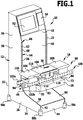
- An embodiment of a balance device according to the invention which in the FIGS. 1 and 2 shown and designated there by 10, comprises a column 12. At the column 12 is (via a below explained in more detail bracket 28) a conveyor belt device 14 and a weighing device 16 is held.
- the column 12 is designed as a hollow body 18 with an interior. It comprises a first side wall 20 and a second side wall 22. The first side wall 20 and the second side wall 22 are spaced apart from each other with a clearance therebetween.
- the first side wall 20 and the second side wall 22 are in particular made of a flat material such as sheet metal.
- the sheet thickness is preferably less than or equal to 3 mm and in particular less than or equal to 2 mm.
- the first side wall 20 and the second side wall 22 each have a standing area 24 and a height extension area 26.
- the height extension area 26 is integrally connected to the standing area 24.
- the scale device 10 is placed on a base.
- a console 28 At the height extension region 26 is a console 28 ( FIG. 4 ), on which in turn the conveyor belt device 14 and the weighing device 16 are held.
- the standing area 24 has a width in a direction perpendicular to a transport direction 30 of the conveyor belt device 14 which is greater than the corresponding width of the height extension area 26.
- the first side wall 20 and the second side wall 22 thereby have an at least approximately L-shape.
- the first side wall 20 and the second side wall 22 each have a rear side 32 with a straight boundary line. Furthermore, they have a bottom 34 with a straight boundary line.
- the underside 34 is formed on the standing area 24 and the rear side 32 on the standing area 24 and the height extension area 26.
- the height extent region 26 of each of the first side wall 20 and the second side wall 22 has a front side 36 with a substantially straight boundary line.
- the standing area 24 of each of the first side wall 20 and the second side wall 22 has an upper side 38.
- the front 36 merges into the top 38 at a transition 40, where the first side wall 20 and the second side wall 22 are each rounded at the respective transition 40 such that the front 36 and top 38 merge into one another continuously rather than in a jump , (The corresponding bounding curve is continuously differentiable.)
- the standing area 24 of each of the first side wall 20 and the second side wall 22 has in each case a front side 42, which has a substantially straight boundary line.
- the front side 42 of the standing area 24 is in particular oriented substantially parallel to the front side 36 of the height extension area 26.
- the column 12 is formed closed in particular to the conveyor belt device 14.
- a front wall 44 is arranged between the front sides 42 of the first side wall 20 and the second side wall 22.
- This front wall 44 also serves as a cross brace between the first side wall 20 and the second side wall 22.
- a front wall 46 is disposed between the front side 36 and the top 38 of the first side wall 20 and the second side wall 22. This follows in its contour the course of the first side wall 20 and the second side wall 22 in this area.
- transverse struts may be arranged (not shown in the drawing).
- the column 12 is further rearwardly through a rear wall 48 (FIG. FIG. 2 ) closed.
- the front wall 46 and the rear wall 48 can serve as cross struts.
- one or more doors 50 are arranged, via which access to the interior of the hollow body 18 of the column 12 is possible.
- the front wall 44 and the front wall 46 are in particular made of a flat material such as sheet metal.
- the rear wall 48 is preferably made of a sheet such as sheet metal.
- a display device 52 is arranged in the region of an upper end of the column 12. This includes in particular a screen on which, for example, operating data of the weighing device 10 can be displayed.
- a printer device is arranged on the column 12, in particular in the area of an upper end.
- the printer device is designed as a label printer device.
- a pivotally arranged cover 54 is indicated, which is arranged next to the display device 52. This cover 54 protects the printer device and in particular a label output, which it covers, against splashing water.
- components may be arranged, for example, a control device of the balance device 10.
- the hollow body 18 is closed at the bottom by a bottom 56. Also, the bottom 56 may be formed as a transverse strut between the first side wall 20 and the second side wall 22.
- the hollow body 18 is formed so that its interior is protected against the ingress of dirt, water, etc. As a result, a cleaning of its outer skin is possible in a simple manner.
- the bottom 56 is preferably made of a sheet such as sheet metal.
- each height adjustable foot elements are arranged.
- the foot elements 58a, 58b, 58c, 58d each have a bottom 60, by means of which they can be set up on the base.
- the bottom 60 protrudes beyond the bottom 56, so that in a deployed scale device 10 of the bottom 56 are spaced from the respective bottom sides 16 of the foot members 58a, 58b, 58c, 58d.
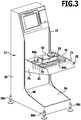
- the underside can be formed on plate elements that are adjustable in height ( FIG. 3 ).
- the first side wall 20 and the second side wall 22 each have a region 62 in the height extension region 26, which protrudes beyond the front wall 44.
- a fixing device 64 which serves to fix the bracket 28 to the column 12, is formed over the region 62.
- the region 62 is bounded in each case by the front side 36 to the front.
- the region 62 with the fixing device 64 comprises a row 66 of through recesses 68. These through recesses 68 are oriented substantially parallel to the transport direction 30.
- the row 66 itself is oriented transversely and in particular perpendicular to the transport direction 30. When set up scale device 10, the row 66 is oriented in particular substantially parallel to the direction of gravity.
- first side wall 20 and second side wall 22 are oriented substantially parallel to the direction of gravity.
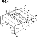
- the console 28 includes a first console wall 70 and a second console wall 72 (FIG. FIG. 4 ).
- the first console wall 70 and the second console wall 72 have a long (rear) side 74 and a short (front) side 76.
- the long side 74 faces the pillar 12 and the short side 76 faces away from the pillar 12.
- the long side 74 and the short side 76 are, for example, at least approximately parallel to each other and aligned, for example, at least approximately parallel to the direction of gravity when the balance device 10 is correctly positioned.
- the first console wall 70 and the second console wall 72 further comprise a top side 78 and a bottom side 80.
- the top side 78 has a substantially straight boundary line, this boundary line being oriented transversely and in particular perpendicular to the transport direction 30. Furthermore, the top surface 78 is preferably oriented substantially perpendicular to the direction of gravity.
- the bottom 80 is oriented to form the trapezoidal shape obliquely to the direction of gravity.
- the first console wall 70 and the second console wall 72 have folds 79 and 81 on their upper side 78 and lower side 80, respectively. These folds 79 and 81 extend at least over a partial length of the upper side 78 or the lower side 80.
- the fold 81 is directed inwardly on the underside 80 of the first console wall 70 and the second console wall 72, d. H. the corresponding folds 81 on the first console wall 70 and the second console wall 72 face each other.
- the folds 79 on the top 78 of the first console wall 70 and the second console wall 72 face outwardly, d. H. they are turned away from each other.
- the rigidity of the first console wall 70 and the second console wall 72 is increased. Furthermore, a support surface for mounting the conveyor belt device 14 is provided by the folds 79.
- a contact surface for fixing transverse struts is provided by the folds 81.
- the first console wall 70 and the second console wall 72 are each made of a flat material and in particular of sheet metal. Preferably, they are made of the same material as the column 12.
- the sheet thickness is preferably less than or equal to 3 mm and in particular less than or equal to 2 mm.
- transverse struts 82, 83 are arranged, which ensure transverse stability of the console 28.
- a transverse strut 82 is arranged in the region of the short side 76, this transverse strut 82 connecting the first console wall 70 and the second console wall 72 in the region of the short side 76.
- a crossbar 82 is provided, which is arranged in the vicinity of the long side 74 and connects there the first console wall 70 and the second console wall 72.
- transverse struts 84a, 84b which are fixed at one end to the first console wall 70 and at the other end to the second console wall 72. These transverse struts 84a, 84b are used for mounting and fixing the weighing device 16 on the console 28 (FIG. FIG. 3 ).
- the bracket 28 is preferably formed as an open hollow body, which includes an interior which is located between the first console wall 70 and the second console wall 72.
- the console 28 is open upwards and downwards. It can thus be easily cleaned and the emergence of seed is avoided.
- transverse struts 82 can be produced by bending.
- the crossbar 82 is formed to overlap the first console wall 70 and the second console wall 72 at the top 78 thereof with an overlap region 86.
- the console 28 is held on the column 12 via the first console wall 70 and the second console wall 72.
- the first console wall 70 is connected directly to the first side wall 20 and the second console wall 72 is connected directly to the second side wall 22.
- the first console wall 70 and the second console wall 72 have a fixing device 88 for this purpose.
- the fixing device 88 of the bracket 28 comprises a row 90 of through recesses 92.
- the through recesses 92 are arranged in particular at the same distance as the through recesses 68 of the row 66 of the fixing device 64 of the column 12 or at a distance which the distance of the continuous Recesses 68 is compatible.
- the row 90 is oriented transversely and in particular perpendicular to the transport direction 30 when the scale device 10 is correctly set up and the bracket 28 is fixed to the column 12.
- the bracket 28 is held on the column 12 in that fixing elements 94 are guided through the through recesses 68 and the through recesses 92 and are locked against displacement parallel to the transport direction 30 ( FIG. 5 ).
- fixing elements 94 are guided through the through recesses 68 and the through recesses 92 and are locked against displacement parallel to the transport direction 30 ( FIG. 5 ).
- the corresponding console wall 70 or 72 on the side wall 20 and 22 via a plurality of such fixing elements 94 held in order to obtain a secure and stable connection.
- the securing with respect to the mobility in the transport direction 30 can take place via a thread formation of the continuous recesses 68, 92 or via corresponding counter elements such as nut elements 95.
- the fixing elements 94 are screw elements which may be secured by nuts.
- bolt connections can also be provided.
- the first console wall 70 is directly connected to and touches the first side wall 20.
- the first console wall 70 and the first side wall 20 overlap. This overlapping area is determined by the width of the area 62 and the width of the first console wall 70 on the fixing device 88. Via the fixing elements 94, the first console wall 70 can be clamped to the first side wall 20.
- FIG. 6 In an alternative embodiment of the connection between the console walls and the side walls, which in FIG. 6 is shown schematically, meet the respective side walls (such as the first side wall 20 and the first console wall 70) frontally to each other.
- the first side wall has, as described above, through recesses 68 and the first console wall has, as described above, through recesses 92.
- the first side wall 20 and the first console wall 70 in particular have the same thickness. (The same applies mutatis mutandis to the second side wall 22 and the second console wall 72.)
- retaining tabs 118, 120 are arranged, which each have spaced-apart recesses 122a, 122b.
- the recesses 122a of the retaining tabs 118, 120 are arranged in alignment with the through recess 92 of the first console wall 70.
- the recesses 122b of the retaining tabs 118 and 120 are arranged in alignment with the through recess 68 of the first side wall 20.
- the retaining tabs 118 and 120 are connected to the first side wall 20 via one or more fixing elements 124, wherein a fixing element 124 through the recess 122 b of the retaining tab 118, through the through recess 68 of the first wall 20 and through the recess 122 b of the retaining tab 120 is immersed and is formed so that the first side wall 20 is clamped between the retaining tabs 118 and 120.
- the first console wall 70 is thereby jammed between the first retaining tab 118 and the second retaining tab 120.
- the retaining tabs 118 and 120 bridge the first side wall 20 and the first console wall 70 and fix them relative to each other.
- the force which runs through the first console wall 70 is divided on both sides on the retaining tabs 118 and 120 and introduced via this with minimal transverse forces in the first side wall 20.
- the position of the console 28 in its height with respect to a standing device 96 which is formed between the standing area 24 of the first side wall 20 and the second side wall 22, detectably adjustable.
- the standing device 96 is filled with ballast material such as gravel or concrete to "lower" the center of gravity of the scale device 10.
- the first console wall 70 forms a continuation of the first side wall 20 forward.
- the second console wall 72 forms a continuation of the second side wall 22 to the front.
- the force profile through the first console wall 70 and the first side wall 20 and, analogously thereto, through the second console wall 72 and the second side wall 22 is transversely offset only by one wall thickness. In accordance with thin designed walls (with a thickness of 3 mm or smaller), this transverse displacement of the force curve is minimal.
- first console wall 70 and the first side wall 20 are integrally connected and the second console wall 72 and the second side wall 22 are integrally connected.
- the weighing device 16 and the conveyor belt device 14 are arranged on the console 28, the weighing device 16 and the conveyor belt device 14 are arranged.
- the conveyor belt device 14 is seated on a carrier device 100, which sits on the upper side 78 of the console walls 70, 72.
- a combination 98 of the conveyor belt device 14 with carrier device 100 and weighing device 16 is supported by the bracket 28.
- This carrier device 100 is supported on the bracket 28 and in particular the folds 79. It is supported in particular on the upper sides 78 of the first console wall 70 and the second console wall 72.
- the support means includes rails 102a, 102b.
- These rails 102a, 102b are in particular made of a flat material such as sheet metal and have a profiling.
- the profiling is, for example, such that the rails 102a, 102b can be placed on the bracket 28 (and can be fixed thereto) and the conveyor belt device 14 can be placed on the rails 102a, 102b (and can be fixed thereto).
- the rails 102a, 102b have a corner profile, which is approximately a U-profile with at most slight rounding of the corners or edges.
- the carrier device 100 is oriented in particular parallel to the transport direction 30. Accordingly, the rails 102a, 102b are oriented at least approximately parallel to the transport direction 30.
- the carrier device 100 has, parallel to the transport direction 30, a length which is at least as great as the distance between the first console wall 70 and the second console wall 72. The carrier device 100 can thereby be supported on the first console wall 70 and the second console wall 72.
- the conveyor belt device 14 comprises three sections, namely a first section 104, a second section 106 and a third section 108. These three sections 104, 106, 108 are mounted separately on the carrier device 100.
- the first section 104 is followed by the second section 106 in the transport direction 30 and the third section 108 is followed by the second section 106 in the transport direction 30.
- the second section 106 is a middle section.
- the first section 104 serves to supply weighing material to the second section 106.
- the third section 108 serves to discharge weighing material from the second section 106.
- the first section 104 comprises a conveyor belt 110 as a feed belt, which is in particular driven.
- the conveyor belt 110 is arranged on a conveyor belt carrier 112, which in turn is fixed to the carrier device 100.
- the third section 108 is basically the same as the first section 104. It includes a discharge conveyor.
- the second section 106 is a weighing section. It comprises a conveyor belt 114 as a weighing belt, which is guided on a conveyor belt carrier 116.
- the conveyor belt carrier 116 is supported on a load cell of the weighing device 16. As a result, the weight of weighing material which is transported on the second section 106 can be detected. (The total weight is determined, from which by subtracting the weight of the conveyor belt 114 with the conveyor belt carrier 116, the weight of the sample is determined.)
- the second section 106 is fixed to the bracket 28 on the transverse struts 84a, 84b. With the second section 106, the weighing device 116 is also mounted on the bracket 28 on the transverse struts 84a, 84b and thereby supported on the first console wall 70 and the second console wall 72.
- the conveyor belt device 14 and the weighing device 16 exert a force on the bracket 28 and the column 12.
- An essential component of this force is the weight.
- This force acts on the carrier device 100 and is introduced via the topsides 78 into the first console wall 70 and the second console wall 72. It passes through the first console wall 70, 72, as in FIG FIG. 2 indicated.
- the force curve is substantially parallel to the first console wall 70 and the second console wall 72.
- transverse forces are minimized with an orientation transversely and in particular perpendicular to the first console wall 70, 72 and torsional forces.
- Such lateral forces (compressive forces) and torsional forces can lead to deformation of a flat material.
- first console wall 70 and the second console wall 72 By the first console wall 70 and the second console wall 72, these forces, without significant lateral forces are generated, led to the first side wall 20 and the second side wall 22 and from there into the standing area 74 respectively of the first side wall 20 and the second side wall 22 introduced , Due to the contacting connection between the first console wall 70 and the first side wall 20 and the second console wall 72 and the second side wall 22, only a small transverse force deflection takes place at the fixing devices 88 and 64. In turn, the forces can be in the first side wall 20 and the second Introduce side wall 22 substantially parallel to these, so that in turn lateral forces and in particular pressure forces are avoided or greatly reduced.
- first console wall 70 and the first side wall 20 and the second console wall 72 and the second side wall 22 are transmitted through the body of the first console wall 70 and the first side wall 20 and the second console wall 72 and the second side wall 22 in parallel (in plane) without significant lateral force deflection to shear forces (Pressure forces) to avoid.
- the introduction into the first side wall 20 and the second side wall 22 continues to take place with minimal transverse forces and the passage through the first side wall 20 and the second side wall 22 also takes place substantially parallel.
- the scale device 10 can be produced in a simple and cost-effective manner.
- the force distribution in the first console wall 70 and the second console wall 72 as well as in the first side wall 20 and the second side wall 22 is optimized with respect to the use of a flat material.
- the console 28 can be configured in a simple manner so that the center of gravity of the scale device 10 is below or within the standing device 96.
- the column 12 can be produced as a hollow body.
- the console 28 does not have to be solid, but it can be produced as a hollow body, in particular from a flat material.
- the weighing device 10 according to the invention is used, for example, as a checkweigher device. She is fed packaged goods and it is checked whether a weight is correct.
- the scale device 10 is then in particular an element of a production / control chain.
- the solution according to the invention allows it to be adapted in its dimensions to a given production / control chain in a simple manner.
- the shape of the column 12 and the bracket 28 is easily adaptable, since the column 12 and the bracket 28 can be easily produced from a sheet such as sheet metal.
- a given scale device 10 can be easily adapted by fixing the bracket 28 at the appropriate height on the column 12.
- the weighing device 10 During operation of the weighing device 10, items to be weighed are coupled in via the first section 104 of the conveyor belt device 14. The weighing sample is then fed to the second section 106 and weighed there via the weighing device 16. The weighing result is displayed, for example, on the display device 52.
Landscapes
- Physics & Mathematics (AREA)
- General Physics & Mathematics (AREA)
- Structure Of Belt Conveyors (AREA)
- Sorting Of Articles (AREA)
Description
- Die Erfindung betrifft eine Waagenvorrichtung, umfassend eine Wägeeinrichtung, eine Förderbandeinrichtung, über welche der Wägeeinrichtung Wägegut zuführbar ist, eine Säule, welche als Hohlkörper ausgebildet ist, mit einer ersten Seitenwand und einer beabstandeten zweiten Seitenwand, und eine Konsole mit einer Konsolenwand und einer zweiten Konsolenwand.
- Aus der
DE 10 2005 006 002 A1 ist eine Kontrollwaage mit einem Maschinenkörper bekannt, wobei der Maschinenkörper aus einem rückseitigen Hohlkörper und einer frontseitigen Aufspannplatte besteht, welche den Hohlkörper zumindest an zwei einander gegenüberliegenden Seiten zumindest stellenweise überragt und so einen Befestigungsflansch ausbildet. - Aus der
JP 09297051 A - Aus der
EP 1 416 256 A1 ist ein Behälter zum Sammeln von zurückgewiesenen Artikeln bei einer Gewichtsprüfungsmaschine bekannt. - Der Erfindung liegt die Aufgabe zugrunde, eine Waagenvorrichtung der eingangs genannten Art bereitzustellen, welche auf einfache Weise herstellbar ist.
- Diese Aufgabe wird bei der eingangs genannten Waagenvorrichtung erfindungsgemäß dadurch gelöst, dass die erste Konsolenwand direkt mit der ersten Seitenwand verbunden ist und die zweite Konsolenwand direkt mit der zweiten Seitenwand verbunden ist, dass die erste Konsolenwand eine Fortsetzung der ersten Seitenwand ist, dass die zweite Konsolenwand die Fortsetzung der zweiten Seitenwand ist, wobei die ausgeübten Kräfte durch die erste Konsolenwand und die zweite Konsolenwand hindurch in die erste Seitenwand und die zweite Seitenwand eben durchgeleitet sind und der Kraftverlauf höchstens um eine Wanddicke querversetzt ist, und dass die Förderbandeinrichtung und die Wägeeinrichtung an der Konsole sitzen, wobei die Konsole die Förderbandeinrichtung und die Wägeeinrichtung hält.
- Bei der erfindungsgemäßen Lösung werden Kräfte (insbesondere Gewichtskräfte), welche durch die Förderbandeinrichtung und die Wägeeinrichtung ausgeübt werden, die an der Konsole sitzen, in die erste Konsolenwand und die zweite Konsolenwand eingeleitet und von dort in die erste Seitenwand und die zweite Seitenwand eingeleitet.
- Dadurch, dass die Förderbandeinrichtung und die Wägeeinrichtung an der Konsole sitzen, lässt sich die Einleitung definiert durchführen mit einer Kraftrichtung, welche innerhalb der ersten Konsolenwand und der zweiten Konsolenwand liegt. Dadurch sind Querkräfte (Druckkräfte), welche normal zu der ersten Konsolenwand und der zweiten Konsolenwand wirken, minimiert. Dadurch wiederum lassen sich die erste Konsolenwand und die zweite Konsolenwand aus einem Flachmaterial wie beispielsweise Blech herstellen.
- Die Kräfte lassen sich durch die erste Konsolenwand und die zweite Konsolenwand mit minimierter Kraftumlenkung (in eine Querrichtung) durchleiten und in die erste Seitenwand und die zweite Seitenwand einleiten. Sie lassen sich dort wiederum parallel zu einer Oberfläche der ersten Seitenwand und der zweiten Seitenwand ableiten. Dadurch lässt sich auch die ersten Seitenwand und die zweite Seitenwand jeweils aus einem Flachmaterial und insbesondere Blech herstellen.
- Die erfindungsgemäße Waagenvorrichtung lässt sich auf einfache und kostengünstige Weise herstellen, da für die Säule und die Konsole Flachmaterialien einsetzbar sind. Die Konsole lässt sich insbesondere als offener Hohlkörper ausbilden. Durch die optimierte Krafteinleitung und -ableitung erhält man eine hohe Stabilität bei einfacher Herstellbarkeit.
- Die erfindungsgemäße Waagenvorrichtung weist eine hohe Torsionssteifigkeit an der Säule und Konsole auf. Dadurch sind Wägeergebnisse mit hoher Genauigkeit reproduzierbar.
- Die erfindungsgemäße Waagenvorrichtung lässt sich auf einfache Weise an Anwendungen anpassen. Beispielsweise wird sie als Kontrollwaagenvorrichtung eingesetzt, um zu kontrollieren, ob Wägegut innerhalb von Toleranzgrenzen ein vorgegebenes Gewicht aufweist. Eine solche Kontrollwaagenvorrichtung ist üblicherweise Teil einer Fertigungskette und/oder Kontrollkette. Durch die einfache Herstellbarkeit lässt sich die erfindungsgemäße Waagenvorrichtung auf einfache Weise so ausgestalten, dass sie in eine Fertigungskette bzw. Kontrollkette einpassbar ist.
- Die erste Konsolenwand ist eine Fortsetzung der ersten Seitenwand. Dadurch lässt sich die Kräfteeinleitung von der ersten Konsolenwand in die erste Seitenwand optimieren mit Minimierung der Kraftumlenkungsrichtung.
- Die erste Konsolenwand ist direkt mit der ersten Seitenwand verbunden. Dadurch ist die Krafteinleitung optimiert. Dadurch lassen sich die erste Konsolenwand und die erste Seitenwand aus einem Flachmaterial herstellen.
- Es ist ferner günstig, wenn die erste Konsolenwand und die erste Seitenwand sich berühren. Dadurch lässt sich die Konsole auf einfache Weise an der Säule fixieren, wobei die Krafteinleitung so erfolgt, dass Flachmaterialien und insbesondere Blechmaterialien einsetzbar sind.
- Die zweite Konsolenwand ist die Fortsetzung der zweiten Seitenwand, die zweite Konsolenwand ist direkt mit der zweiten Seitenwand verbunden und günstigerweise berühren sich die zweite Konsolenwand und die zweite Seitenwand.
- Die erfindungsgemäße Waagenvorrichtung lässt sich auf einfache und kostengünstige Weise herstellen, wenn die erste Seitenwand und die zweite Seitenwand aus einem Flachmaterial hergestellt sind. Aus dem gleichen Grund ist es günstig, wenn die erste Konsolenwand und die zweite Konsolenwand aus einem Flachmaterial hergestellt sind. Durch Schneiden und Biegen des Flachmaterials lassen sich die entsprechenden Elemente der Waagenvorrichtung auf einfache Weise herstellen, wobei eine große Variabilität vorliegt.
- Das Flachmaterial ist insbesondere Blech.
- Insbesondere weist das Flachmaterial eine Dicke auf, welche kleiner oder gleich 3 mm ist. Es kann dabei insbesondere vorgesehen sein, dass diese Dicke kleiner oder gleich 2 mm ist. Durch die erfindungsgemäße Lösung lässt sich eine Waagenvorrichtung realisieren, welche eine hohe Steifigkeit aufweist, wobei diese hohe Steifigkeit auch trotz der Verwendung von dünnen Flachmaterialien wie dünnen Blechen erreichbar ist.
- Es kann vorgesehen sein, dass die erste Konsolenwand einstückig mit der ersten Seitenwand und die zweite Konsolenwand einstückig mit der zweiten Seitenwand verbunden ist. Dadurch ergibt sich eine optimierte Krafteinleitung von der Konsole in die Säule.
- Eine hohe Variabilität ergibt sich, wenn die Konsole lösbar an der Säule fixierbar ist. Dadurch kann die Position der Konsole bezüglich der Säule eingestellt werden. Ferner lässt sich beispielsweise für die Reinigung der Waagenvorrichtung die Konsole abnehmen.
- Insbesondere ist es vorgesehen, dass die Konsole höhenverstellbar an der Säule fixierbar ist. Dadurch lässt sich auf einfache Weise die Waagenvorrichtung beispielsweise an eine bestehende Fertigungskette oder Kontrollkette einpassen.
- Günstig ist es, wenn zwischen der ersten Seitenwand und der zweiten Seitenwand eine Fixierungseinrichtung für die Konsole angeordnet ist. Dadurch lässt sich die Konsole auf einfache Weise an der Säule montieren und fixieren.
- Bei einer Ausführungsform umfasst die Fixierungseinrichtung durchgehende Ausnehmungen für Fixierungselemente. Dadurch lässt sich die Konsole beispielsweise formschlüssig an der Säule fixieren.
- Ganz besonders vorteilhaft ist es, wenn die durchgehenden Ausnehmungen mindestens näherungsweise parallel zu einer Transportrichtung der Förderbandeinrichtung orientiert sind. Es lassen sich dann die jeweilige Seitenwand und Konsolenwand miteinander verbinden, wobei die Kraftumlenkung bezüglich Querkräften (Druckkräften) minimierbar ist.
- Es kann vorgesehen sein, dass die Fixierungseinrichtung mindestens eine Reihe an durchgehenden Ausnehmungen umfasst, wobei die Reihe quer zu einer Transportrichtung der Förderbandeinrichtung orientiert ist. Dadurch lässt sich auf einfache Weise eine Höhenverstellbarkeit der Konsole an der Säule realisieren. Ferner ist es möglich, die Konsole über eine Mehrzahl von Fixierungselementen an der Säule zu fixieren, um eine hohe Stabilität der Waagenvorrichtung zu erreichen.
- Vorteilhafterweise weisen die erste Konsolenwand und die zweite Konsolenwand eine Fixierungseinrichtung zur Fixierung an der Säule auf. Die Fixierungseinrichtung kooperiert insbesondere mit einer Fixierungseinrichtung, welche an der Säule angeordnet ist.
- Günstig ist es, wenn die Fixierungseinrichtung durchgehende Ausnehmungen für Fixierungselemente aufweist. Dadurch lässt sich die Konsole beispielsweise über Schraubelemente oder Bolzenelemente mit der Säule fixieren.
- Insbesondere sind die durchgehenden Ausnehmungen mindestens näherungsweise parallel zu einer Transportrichtung der Förderbandeinrichtung orientiert. Dadurch lässt sich bei für Flachmaterial optimierter Kraftführung die Waagenvorrichtung auf einfache Weise herstellen.
- Günstig ist es, wenn die Fixierungseinrichtung mindestens eine Reihe an durchgehenden Ausnehmungen umfasst, wobei die Reihe quer zu einer Transportrichtung der Förderbandeinrichtung orientiert sind. Dadurch lässt sich die Konsole auf einfache Weise an der Säule fixieren. Es ist dabei eine Fixierung der ersten Konsolenwand an der ersten Seitenwand und der zweiten Konsolenwand an der zweiten Seitenwand mittels einer Mehrzahl von Fixierungselementen wie Schraubelementen möglich, um einen sicheren Halt zu erreichen.
- Günstig ist es, wenn die Konsole über Schraubenelemente und/oder Bolzenelemente mittels der ersten Konsolenwand und der zweiten Konsolenwand an der Säule fixiert ist. Über Schraubenelemente bzw. Bolzenelemente lässt sich die relative Beweglichkeit zwischen der Konsole und der Säule insbesondere in einer Richtung parallel zur Transportrichtung der Förderbandeinrichtung sperren. In einer Richtung wird die Beweglichkeit über Schraubenköpfe bzw. Bolzenköpfe gesperrt und in der anderen Richtung wird die Beweglichkeit über Anlageelemente wie beispielsweise Mutterelemente gesperrt.
- Günstig ist es, wenn die erste Seitenwand und die erste Konsolenwand einander überlappen. Dadurch lässt sich die Krafteinleitung von der ersten Konsolenwand in die erste Seitenwand für Flachmaterialien optimieren, so dass eine einfache Herstellbarkeit der Waagenvorrichtung ermöglicht ist.
- Aus dem gleichen Grund ist es günstig, wenn die zweite Seitenwand und die zweite Konsolenwand einander überlappen.
- Günstigerweise ist zwischen der ersten Konsolenwand und der zweiten Konsolenwand mindestens eine Querstrebe angeordnet. Es kann dabei vorgesehen sein, dass die erste Konsolenwand und die zweite Konsolenwand einstückig über mindestens eine Querstrebe miteinander verbunden sind. Durch die mindestens eine Querstrebe erhält man eine Querstabilität. An Querstreben kann auch die Wägeeinrichtung fixiert werden.
- Günstigerweise weisen die erste Konsolenwand und die zweite Konsolenwand jeweils eine trapezförmige Gestalt mit einer langen Seite, welche der Säule zugewandt ist, und mit einer kurzen Seite, welche der Säule abgewandt ist, auf. Dadurch lässt sich die Abstützung der Konsole an der Säule optimieren.
- Günstigerweise ist eine Unterseite der ersten Konsolenwand und der zweiten Konsolenwand jeweils schräg zur Schwerkraftrichtung orientiert. Dadurch erhält man eine optimierte Abstützung der Konsole an der Säule.
- Es ist ferner günstig, wenn eine Oberseite der ersten Konsolenwand und der zweiten Konsolenwand jeweils im Wesentlichen senkrecht zur Schwerkraftrichtung orientiert ist. Dadurch erhält man eine flache Oberseite, auf welcher die Förderbandeinrichtung aufsetzbar ist.
- Günstig ist es, wenn die erste Seitenwand und die zweite Seitenwand jeweils einen Standbereich und einen Höhenerstreckungsbereich aufweisen, wobei die Waagenvorrichtung über die Standbereiche auf einer Unterlage aufgestellt ist und die Konsole an den Höhenerstreckungsbereichen angeordnet ist. Durch die verbreiterten Standbereiche (mit einer Breite quer zur Transportrichtung der Förderbandeinrichtung) lassen sich über die Konsole eingeleitete Kräfte optimal ableiten, so dass sich eine hohe mechanische Stabilität für die Waagenvorrichtung ergibt.
- Es ist dann günstig, wenn die erste Seitenwand und die zweite Seitenwand jeweils eine L-förmige Gestalt aufweisen, um einen optimalen Stand zu gewährleisten.
- Günstigerweise weist die Säule eine Standeinrichtung auf, welche sich zwischen dem Standbereich der ersten Seitenwand und dem Standbereich der zweiten Seitenwand erstreckt, wobei der Schwerpunkt der Waagenvorrichtung innerhalb oder unterhalb der Standeinrichtung liegt. Dadurch lässt sich die Waagenvorrichtung stabil aufstellen. Die Standeinrichtung ist zur "Tieferlegung" des Schwerpunkts insbesondere mit einem Ballastmaterial wie Kies oder Beton gefüllt.
- Vorteilhaft ist es, wenn die erste Seitenwand und die zweite Seitenwand am Übergang zwischen dem Höhenerstreckungsbereich und dem Standbereich jeweils abgerundet ausgebildet sind. Dadurch lässt sich die Kräfteableitung optimieren. Der Übergang hat die gleiche Funktionsweise wie der Übergangsbereich an einem Baumstamm zum Wurzelbereich. (Die Standbereiche entsprechen dem Wurzelbereich und die Säule dem Baumstamm.)
- Günstig ist es, wenn die Förderbandeinrichtung auf einer Trägereinrichtung angeordnet ist. Dadurch lässt sich die Förderbandeinrichtung auf einfache Weise auf der Konsole positionieren und die Position ist veränderbar (beispielsweise parallel zu einer Transportrichtung).
- Es ist besonders vorteilhaft, wenn die Wägeeinrichtung innerhalb oder unterhalb der Trägereinrichtung angeordnet ist. Dadurch lässt sich die Wägeeinrichtung auf einfache und platzsparende Weise an der Konsole anordnen. Sie lässt sich dadurch auch von der Trägereinrichtung entkoppeln, um so ein Wägeergebnis minimal zu beeinflussen. (Es kann beispielsweise vorgesehen sein, dass über einen Schieber (Pusher) Wägegut nach der Wägung, welches außerhalb eines Toleranzbereichs liegt, "weggestoßen" wird, um es aus der Transportkette zu nehmen. Dieser Vorgang kann einen Impuls auf die Trägereinrichtung verursachen. Durch die Anordnung der Wägeeinrichtung innerhalb oder unterhalb der Trägereinrichtung an der Konsole ist eine Impulsentkopplung erreicht.) Ferner lässt sich die Wägeeinrichtung auf einfache Weise ausgestalten, da die Konsole keinen Einfluss auf das Wägeergebnis hat, wenn diese genügend biegesteif ausgebildet ist.
- Bei einer Ausführungsform umfasst die Trägereinrichtung mindestens eine Schiene. Eine solche Trägereinrichtung lässt sich auf einfache Weise herstellen. Die mindestens eine Schiene lässt sich auf einfache Weise auf die erste Konsolenwand und die zweite Konsolenwand aufsetzen, um optimiert Kräfte in die Konsole einleiten zu können.
- Insbesondere ist die mindestens eine Schiene mindestens näherungsweise parallel zu einer Transportrichtung der Förderbandeinrichtung orientiert. Dadurch lassen sich auf einfache Weise von der Kombination aus der Förderbandeinrichtung und der Wägeeinrichtung ausgeübte Kräfte in die Konsolenwände einleiten und über die Seitenwände der Säule ableiten.
- Beispielsweise ist die mindestens eine Schiene aus einem Flachmaterial hergestellt. Das Flachmaterial ist beispielsweise Blech. Die mindestens eine Schiene und damit die Trägereinrichtung lässt sich dadurch auf einfache Weise herstellen. Ferner lässt sich die Waagenvorrichtung mit geringem Gewicht herstellen. Außerdem lässt sich die Wägeeinrichtung so positionieren, dass die Trägereinrichtung nicht als Vorlast wirkt.
- Ganz besonders vorteilhaft ist es, wenn die Trägereinrichtung sich auf der ersten Konsolenwand und der zweiten Konsolenwand abstützt. Dadurch lassen sich die von der Förderbandeinrichtung ausgeübten Kräfte direkt in die erste Konsolenwand und die zweite Konsolenwand einleiten und dabei so einleiten, dass sie in diesen im Wesentlichen parallel zu einer Oberfläche geführt sind und Querkräfte (Druckkräfte) minimiert sind.
- Insbesondere ist eine Kombination aus der Förderbandeinrichtung und der Wägeeinrichtung an der ersten Konsolenwand und der zweiten Konsolenwand direkt und/oder indirekt abgestützt. Beispielsweise ist die Förderbandeinrichtung direkt abgestützt und die Wägeeinrichtung indirekt auf Querstreben, auf denen sie sitzt und die mit den Konsolenwänden verbunden sind. Dadurch lassen sich Kräfte optimiert für Flachmaterialien einleiten.
- Ganz besonders vorteilhaft ist es, wenn die Konsole und die Säule so ausgebildet sind und die Förderbandeinrichtung und die Wägeeinrichtung so angeordnet sind, dass die ausgeübten Kräfte durch die erste Konsolenwand und die zweite Konsolenwand hindurch in die erste Seitenwand und die zweite Seitenwand eingeleitet sind. Wenn die Kräfte durch die erste Konsolenwand und die zweite Konsolenwand eben durchgeleitet werden, dann sind Querkräfte bzw. Druckkräfte minimiert. Es ist dann der Einsatz von Flachmaterialen wie beispielsweise Blechmaterialien möglich. Ferner ergibt sich eine hohe Torsionssteifigkeit. Dadurch lässt sich die Säule und die Konsole mit Flachmaterialien herstellen und damit auf einfache und kostengünstige Weise herstellen.
- Insbesondere sind die Förderbandeinrichtung und die Wägeeinrichtung nach unten durch die Konsole abgestützt, wobei die Stützkräfte in die erste Konsolenwand und die zweite Konsolenwand eingeleitet sind. Dadurch ist die Waagenvorrichtung bezüglich der Ausbildung der Säule und der Konsole aus Flachmaterialien optimiert.
- Es ist ferner günstig, wenn die erste Konsolenwand und die zweite Konsolenwand im Wesentlichen parallel zur Schwerkraftrichtung orientiert sind. Dadurch lassen sich Kräfte optimiert durch die erste Konsolenwand und die zweite Konsolenwand durchleiten und in die Säule einleiten.
- Aus dem gleichen Grund ist es günstig, wenn die erste Seitenwand und die zweite Seitenwand im Wesentlichen parallel zur Schwerkraftrichtung orientiert sind. Es lassen sich dann Querkräfte (Druckkräfte) minimieren, so dass eine optimierte Ausgestaltung bezüglich des Einsatzes von Flachmaterialien möglich ist.
- Die Konsole ist insbesondere ein Hohlkörper. Sie umfasst die erste Konsolenwand und die zweite Konsolenwand und eventuell dazwischenliegende Querstreben. Die Konsole muss dann nicht als massiver Körper ausgebildet werden. Sie ist dementsprechend auf einfache Weise herstellbar und weist ein relativ geringes Gewicht auf. Die Konsole ist insbesondere ein offener Hohlkörper mit (mindestens) einer offenen Seite. Sie kann dann leicht gereinigt werden und ist hygienisch vorteilhaft, da durch die offene Konstruktion keine Keimnester entstehen können.
- Die nachfolgende Beschreibung bevorzugter Ausführungsformen dient im Zusammenhang mit der Zeichnung der näheren Erläuterung der Erfindung. Es zeigen:
- Figur 1
- eine perspektivische Ansicht eines Ausführungsbeispiels einer erfindungsgemäßen Waagenvorrichtung;
- Figur 2
- eine Seitenansicht der Waagenvorrichtung gemäß
Figur 1 ; - Figur 3
- eine perspektivische Darstellung der Waagenvorrichtung gemäß
Figur 1 ohne Förderbandeinrichtung; - Figur 4
- eine perspektivische Ansicht eines Ausführungsbeispiels einer Konsole;
- Figur 5
- eine vergrößerte Darstellung eines Ausführungsbeispiels eines Verbindungsbereichs zwischen einer Konsolenwand und einer Seitenwand; und
- Figur 6
- ein weiteres Ausführungsbeispiel eines Verbindungsbereichs zwischen einer Konsolenwand und einer Seitenwand.
- Ein Ausführungsbeispiel einer erfindungsgemäßen Waagenvorrichtung, welches in den
Figuren 1 und2 gezeigt und dort mit 10 bezeichnet ist, umfasst eine Säule 12. An der Säule 12 ist (über eine unten näher erläuterte Konsole 28) eine Förderbandeinrichtung 14 und eine Wägeeinrichtung 16 gehalten. - Die Säule 12 ist als Hohlkörper 18 ausgebildet mit einem Innenraum. Sie umfasst eine erste Seitenwand 20 und eine zweite Seitenwand 22. Die erste Seitenwand 20 und die zweite Seitenwand 22 sind beabstandet zueinander mit einem Freiraum dazwischen.
- Die erste Seitenwand 20 und die zweite Seitenwand 22 sind insbesondere aus einem Flachmaterial wie Blech hergestellt. Die Blechdicke ist vorzugsweise kleiner gleich 3 mm und insbesondere kleiner gleich 2 mm.
- Die erste Seitenwand 20 und die zweite Seitenwand 22 weisen jeweils einen Standbereich 24 auf und einen Höhenerstreckungsbereich 26. Der Höhenerstreckungsbereich 26 ist einstückig mit dem Standbereich 24 verbunden. Über den Standbereich 24 ist die Waagenvorrichtung 10 auf einer Unterlage aufgestellt. An dem Höhenerstreckungsbereich 26 ist eine Konsole 28 (
Figur 4 ) gehalten, an welcher wiederum die Förderbandeinrichtung 14 und die Wägeeinrichtung 16 gehalten sind. - Der Standbereich 24 weist eine Breite in einer Richtung senkrecht zu einer Transportrichtung 30 der Förderbandeinrichtung 14 auf, welche größer ist als die entsprechende Breite des Höhenerstreckungsbereichs 26. Die erste Seitenwand 20 und die zweite Seitenwand 22 haben dadurch eine mindestens näherungsweise L-Form.
- Die erste Seitenwand 20 und die zweite Seitenwand 22 weisen jeweils eine Hinterseite 32 mit einer geraden Begrenzungslinie auf. Ferner weisen sie eine Unterseite 34 mit einer geraden Begrenzungslinie auf. Die Unterseite 34 ist an dem Standbereich 24 gebildet und die Hinterseite 32 an dem Standbereich 24 und dem Höhenerstreckungsbereich 26.
- Der Höhenerstreckungsbereich 26 jeweils der ersten Seitenwand 20 und der zweiten Seitenwand 22 weist eine Vorderseite 36 mit einer im Wesentlichen geraden Begrenzungslinie auf. Der Standbereich 24 jeweils der ersten Seitenwand 20 und der zweiten Seitenwand 22 weist eine Oberseite 38 auf. Die Vorderseite 36 geht in die Oberseite 38 an einem Übergang 40 über, wobei die erste Seitenwand 20 und die zweite Seitenwand 22 jeweils an dem entsprechenden Übergang 40 abgerundet sind, so dass die Vorderseite 36 und die Oberseite 38 kontinuierlich und nicht in einem Sprung ineinander übergehen. (Die entsprechende Begrenzungskurve ist stetig differenzierbar.)
- Der Standbereich 24 jeweils der ersten Seitenwand 20 und der zweiten Seitenwand 22 weist jeweils eine Vorderseite 42 auf, welche eine im Wesentlichen gerade Begrenzungslinie hat. Die Vorderseite 42 des Standbereichs 24 ist insbesondere im Wesentlichen parallel zu der Vorderseite 36 des Höhenerstreckungsbereichs 26 orientiert.
- Die Säule 12 ist insbesondere zu der Förderbandeinrichtung 14 hin geschlossen ausgebildet. Dazu ist zwischen den Vorderseiten 42 der ersten Seitenwand 20 und der zweiten Seitenwand 22 eine Vorderwand 44 angeordnet. Diese Vorderwand 44 dient auch als Querstrebe zwischen der ersten Seitenwand 20 und der zweiten Seitenwand 22. Ferner ist zwischen der Vorderseite 36 und der Oberseite 38 der ersten Seitenwand 20 und der zweiten Seitenwand 22 eine Vorderwand 46 angeordnet. Diese folgt in ihrer Kontur dem Verlauf der ersten Seitenwand 20 und der zweiten Seitenwand 22 in diesem Bereich. Zwischen der ersten Seitenwand 20 und der zweiten Seitenwand 22 können auch im Innenraum des Hohlkörpers 28 verlaufende Querstreben angeordnet sein (in der Zeichnung nicht gezeigt).
- Die Säule 12 ist weiterhin rückwärtig durch eine Hinterwand 48 (
Figur 2 ) geschlossen. - Auch die Vorderwand 46 und die Hinterwand 48 können als Querstreben dienen.
- An der Hinterwand 48 sind eine oder mehrere Türen 50 angeordnet, über die ein Zugriff auf den Innenraum des Hohlkörpers 18 der Säule 12 möglich ist.
- Die Vorderwand 44 und die Vorderwand 46 sind insbesondere aus einem Flachmaterial wie Blech hergestellt. Weiterhin ist die Hinterwand 48 vorzugsweise aus einem Flachmaterial wie Blech hergestellt.
- Im Bereich eines oberen Endes der Säule 12 ist eine Anzeigeeinrichtung 52 angeordnet. Diese umfasst insbesondere einen Bildschirm, auf dem beispielsweise Betriebsdaten der Waagenvorrichtung 10 anzeigbar sind.
- Es kann beispielsweise auch vorgesehen sein, dass an der Säule 12 insbesondere im Bereich eines oberen Endes eine Druckereinrichtung angeordnet ist. Insbesondere ist die Druckereinrichtung als Etiketten-Druckereinrichtung ausgebildet. In
Figur 1 ist ein schwenkbar angeordneter Deckel 54 angedeutet, welcher neben der Anzeigeeinrichtung 52 angeordnet ist. Dieser Deckel 54 schützt die Druckereinrichtung und insbesondere eine Etikettenausgabe, welche er abdeckt, gegen Spritzwasser. - In dem Innenraum der Säule 12 können Komponenten beispielsweise einer Steuerungseinrichtung der Waagenvorrichtung 10 angeordnet sein.
- Der Hohlkörper 18 ist nach unten hin durch einen Boden 56 geschlossen. Auch der Boden 56 kann als Querstrebe zwischen der ersten Seitenwand 20 und der zweiten Seitenwand 22 ausgebildet sein. Der Hohlkörper 18 ist so ausgebildet, dass sein Innenraum gegen das Eindringen von Schmutz, Wasser usw. geschützt ist. Dadurch ist eine Reinigung seiner Außenhaut auf einfache Weise möglich.
- Auch der Boden 56 ist vorzugsweise aus einem Flachmaterial wie Blech hergestellt.
- An den Eckbereichen sind jeweils höhenverstellbare Fußelemente angeordnet. Insgesamt gibt es vier Fußelemente 58a, 58b, 58c, 58d, wobei das Fußelement 58d in den
Figuren 1 und2 nicht sichtbar ist. Die Fußelemente 58a, 58b, 58c, 58d weisen jeweils eine Unterseite 60 auf, mittels welcher sie auf die Unterlage aufstellbar sind. Die Unterseite 60 ragt über den Boden 56 hinaus, so dass bei einer aufgestellten Waagenvorrichtung 10 der Boden 56 beabstandet zu den jeweiligen Unterseiten 16 der Fußelemente 58a, 58b, 58c, 58d sind. Die Unterseite kann an Tellerelementen gebildet sein, die höhenverstellbar sind (Figur 3 ). - Die erste Seitenwand 20 und die zweite Seitenwand 22 weisen in dem Höhenerstreckungsbereich 26 jeweils einen Bereich 62 auf, welcher über die Vorderwand 44 hinausragt. Über den Bereich 62 ist eine Fixierungseinrichtung 64 gebildet, welche zur Fixierung der Konsole 28 an der Säule 12 dient. Der Bereich 62 ist dabei jeweils durch die Vorderseite 36 nach vorne begrenzt.
- Der Bereich 62 mit der Fixierungseinrichtung 64 umfasst eine Reihe 66 an durchgehenden Ausnehmungen 68. Diese durchgehenden Ausnehmungen 68 sind dabei im Wesentlichen parallel zur Transportrichtung 30 orientiert. Die Reihe 66 selber ist quer und insbesondere senkrecht zur Transportrichtung 30 orientiert. Bei aufgestellter Waagenvorrichtung 10 ist die Reihe 66 insbesondere im Wesentlichen parallel zur Schwerkraftrichtung orientiert.
- (Bei korrekt positionierter Waagenvorrichtung 10 sind die erste Seitenwand 20 und die zweite Seitenwand 22 im Wesentlichen parallel zur Schwerkraftrichtung orientiert.)
- Die Konsole 28 umfasst eine erste Konsolenwand 70 und eine zweite Konsolenwand 72 (
Figur 4 ). Die erste Konsolenwand 70 und die zweite Konsolenwand 72 weisen eine lange (Hinter-)Seite 74 und eine kurze (Vorder-)Seite 76 auf. Die lange Seite 74 ist der Säule 12 zugewandt und die kurze Seite 76 ist der Säule 12 abgewandt. Die lange Seite 74 und die kurze Seite 76 sind dabei beispielsweise mindestens näherungsweise parallel zueinander und bei korrekt positionierter Waagenvorrichtung 10 beispielsweise mindestens näherungsweise parallel zur Schwerkraftrichtung ausgerichtet. - Die erste Konsolenwand 70 und die zweite Konsolenwand 72 umfassen ferner eine Oberseite 78 und eine Unterseite 80. Die Oberseite 78 weist eine im Wesentlichen gerade Begrenzungslinie auf, wobei diese Begrenzungslinie quer und insbesondere senkrecht zur Transportrichtung 30 orientiert ist. Ferner ist die Oberseite 78 vorzugsweise im Wesentlichen senkrecht zur Schwerkraftrichtung orientiert.
- Die Unterseite 80 ist zur Ausbildung der Trapezform schräg zur Schwerkraftrichtung orientiert.
- Die erste Konsolenwand 70 und die zweite Konsolenwand 72 weisen an ihrer Oberseite 78 und Unterseite 80 jeweils Falzungen 79 und 81 auf. Diese Falzungen 79 bzw. 81 erstrecken sich mindestens über eine Teillänge der Oberseite 78 bzw. der Unterseite 80.
- Es ist dabei vorgesehen, dass die Falzung 81 an der Unterseite 80 der ersten Konsolenwand 70 und der zweiten Konsolenwand 72 nach innen gerichtet ist, d. h. die entsprechenden Falzungen 81 an der ersten Konsolenwand 70 und der zweiten Konsolenwand 72 sind einander zugewandt. Die Falzungen 79 an der Oberseite 78 der ersten Konsolenwand 70 und der zweiten Konsolenwand 72 weisen nach außen, d. h. sie sind einander abgewandt.
- Durch die Falzungen 79 und 81 wird die Steifigkeit der ersten Konsolenwand 70 und der zweiten Konsolenwand 72 erhöht. Ferner wird durch die Falzungen 79 eine Auflagefläche zur Montage der Förderbandeinrichtung 14 bereitgestellt.
- Weiterhin wird durch die Falzungen 81 eine Anlagefläche zur Fixierung von Querstreben bereitgestellt.
- Die erste Konsolenwand 70 und die zweite Konsolenwand 72 sind jeweils aus einem Flachmaterial und insbesondere aus Blech hergestellt. Vorzugsweise sind sie aus dem gleichen Material wie die Säule 12 hergestellt. Die Blechdicke ist vorzugsweise kleiner gleich 3 mm und insbesondere kleiner gleich 2 mm.
- Zwischen der ersten Konsolenwand 70 und der zweiten Konsolenwand 72 sind eine oder mehrere Querstreben 82, 83 angeordnet, die für eine Querstabilität der Konsole 28 sorgen. Beispielsweise ist eine Querstrebe 82 im Bereich der kurzen Seite 76 angeordnet, wobei diese Querstrebe 82 die erste Konsolenwand 70 und die zweite Konsolenwand 72 im Bereich der kurzen Seite 76 verbindet. Ferner ist eine Querstrebe 82 vorgesehen, welche in der Nähe der langen Seite 74 angeordnet ist und dort die erste Konsolenwand 70 und die zweite Konsolenwand 72 verbindet.
- Es sind ferner stegförmige beabstandete Querstreben 84a, 84b vorgesehen, welche an einem Ende an der ersten Konsolenwand 70 und an dem anderen Ende an der zweiten Konsolenwand 72 fixiert sind. Diese Querstreben 84a, 84b dienen zur Montage und Fixierung der Wägeeinrichtung 16 an der Konsole 28 (
Figur 3 ). - Die Konsole 28 ist dabei vorzugsweise als offener Hohlkörper ausgebildet, welcher einen Innenraum umfasst, der zwischen der ersten Konsolenwand 70 und der zweiten Konsolenwand 72 liegt. Insbesondere ist die Konsole 28 nach oben und nach unten offen. Sie kann dadurch auf einfache Weise gereinigt werden und das Entstehen von Keimnestern ist vermieden.
- Weitere Querstreben 82 können durch Abkantung hergestellt werden.
- Bei dem gezeigten Ausführungsbeispiel ist die Querstrebe 82 so ausgebildet, dass sie die erste Konsolenwand 70 und die zweite Konsolenwand 72 an deren Oberseite 78 mit einem Überlappungsbereich 86 überlappt.
- Die Konsole 28 ist über die erste Konsolenwand 70 und die zweiten Konsolenwand 72 an der Säule 12 gehalten. Dazu ist die erste Konsolenwand 70 direkt mit der ersten Seitenwand 20 verbunden und die zweite Konsolenwand 72 ist direkt mit der zweiten Seitenwand 22 verbunden. Die erste Konsolenwand 70 und die zweite Konsolenwand 72 weisen dazu eine Fixierungseinrichtung 88 auf.
- Die Fixierungseinrichtung 88 der Konsole 28 umfasst eine Reihe 90 an durchgehenden Ausnehmungen 92. Die durchgehenden Ausnehmungen 92 sind insbesondere im gleichen Abstand wie die durchgehenden Ausnehmungen 68 der Reihe 66 der Fixierungseinrichtung 64 der Säule 12 angeordnet oder mit einem Abstand, welcher zu dem Abstand der durchgehenden Ausnehmungen 68 kompatibel ist. Die Reihe 90 ist quer und insbesondere senkrecht zu der Transportrichtung 30 orientiert, wenn die Waagenvorrichtung 10 korrekt aufgestellt ist und die Konsole 28 an der Säule 12 fixiert ist.
- Die Konsole 28 ist an der Säule 12 dadurch gehalten, dass Fixierungselemente 94 durch die durchgehenden Ausnehmungen 68 und die durchgehenden Ausnehmungen 92 geführt sind und gegenüber Verschieblichkeit parallel zur Transportrichtung 30 gesperrt sind (
Figur 5 ). Insbesondere ist die entsprechende Konsolenwand 70 bzw. 72 an der Seitenwand 20 bzw. 22 über eine Mehrzahl solcher Fixierungselemente 94 gehalten, um eine sichere und stabile Verbindung zu erhalten. - Die Sicherung bezüglich der Beweglichkeit in der Transportrichtung 30 kann über eine Gewindeausbildung der durchgehenden Ausnehmungen 68, 92 erfolgen oder über entsprechende Gegenelemente wie Mutterelemente 95. Beispielsweise handelt es sich bei den Fixierungselementen 94 um Schraubenelemente, welche über Muttern gesichert sein können.
- Beispielsweise können auch Bolzenverbindungen vorgesehen sein.
- Die erste Konsolenwand 70 ist direkt mit der ersten Seitenwand 20 verbunden und berührt diese. Die erste Konsolenwand 70 und die erste Seitenwand 20 überlappen. Dieser Überlappungsbereich ist durch die Breite des Bereichs 62 und die Breite der ersten Konsolenwand 70 an der Fixierungseinrichtung 88 bestimmt. Über die Fixierungselemente 94 lässt sich die erste Konsolenwand 70 an die erste Seitenwand 20 spannen.
- Gleiches gilt auch für die zweite Konsolenwand 72 und die zweite Seitenwand 22.
- Bei einem alternativen Ausführungsbeispiel der Verbindung zwischen den Konsolenwänden und den Seitenwänden, welches in
Figur 6 schematisch gezeigt ist, treffen die entsprechenden Seitenwände (wie beispielsweise die erste Seitenwand 20 und die erste Konsolenwand 70) stirnseitig aufeinander. Die erste Seitenwand weist dabei wie oben beschrieben durchgehende Ausnehmungen 68 auf und die erste Konsolenwand weist wie oben beschrieben durchgehende Ausnehmungen 92 auf. - Die erste Seitenwand 20 und die erste Konsolenwand 70 weisen dabei insbesondere die gleiche Dicke auf. (Gleiches gilt sinngemäß auch für die zweite Seitenwand 22 und die zweite Konsolenwand 72.)
- Jeweils beidseitig der ersten Seitenwand 20 und der ersten Konsolenwand 70 sind Haltelaschen 118, 120 angeordnet, welche jeweils beabstandete Ausnehmungen 122a, 122b aufweisen. Die Ausnehmungen 122a der Haltelaschen 118, 120 sind fluchtend zu der durchgehenden Ausnehmung 92 der ersten Konsolenwand 70 angeordnet. Die Ausnehmungen 122b der Haltelaschen 118 und 120 sind fluchtend zu der durchgehenden Ausnehmung 68 der ersten Seitenwand 20 angeordnet.
- Die Haltelaschen 118 und 120 sind mit der ersten Seitenwand 20 über ein oder mehrere Fixierungselemente 124 verbunden, wobei ein Fixierungselement 124 durch die Ausnehmung 122b der Haltelasche 118, durch die durchgehende Ausnehmung 68 der ersten Wand 20 und durch die Ausnehmung 122b der Haltelasche 120 durchgetaucht ist und dabei so ausgebildet ist, dass die erste Seitenwand 20 zwischen den Haltelaschen 118 und 120 eingeklemmt ist.
- Ferner ist ein Fixierungselement 126 durch die Ausnehmung 122a der Haltelasche 118, die durchgehende Ausnehmung 92 der ersten Konsolenwand 70 und die Ausnehmung 122a der Haltelasche 120 durchgetaucht und in seiner Beweglichkeit parallel zur Transportrichtung 30 gesperrt. Die erste Konsolenwand 70 ist dadurch zwischen der ersten Haltelasche 118 und der zweiten Haltelasche 120 verklemmt.
- Die Haltelaschen 118 und 120 überbrücken die erste Seitenwand 20 und die erste Konsolenwand 70 und fixieren diese relativ zueinander. Die Kraft, welche durch die erste Konsolenwand 70 hindurchverläuft, wird beidseitig auf die Haltelaschen 118 und 120 aufgeteilt und über diese mit minimierten Querkräften in die erste Seitenwand 20 eingeleitet.
- Über die Reihen 66 und 90 ist die Position der Konsole 28 in ihrer Höhe bezüglich einer Standeinrichtung 96, welche zwischen dem Standbereich 24 der ersten Seitenwand 20 und der zweiten Seitenwand 22 gebildet ist, feststellbar einstellbar. Die Standeinrichtung 96 ist mit Ballastmaterial wie Kies oder Beton gefüllt, um den Schwerpunkt der Waagenvorrichtung 10 "tiefer zu legen".
- Die erste Konsolenwand 70 bildet eine Fortsetzung der ersten Seitenwand 20 nach vorne. Die zweite Konsolenwand 72 bildet eine Fortsetzung der zweiten Seitenwand 22 nach vorne. Der Kraftverlauf durch die erste Konsolenwand 70 und die erste Seitenwand 20 und analog dazu durch die zweite Konsolenwand 72 und die zweite Seitenwand 22 ist nur um eine Wanddicke querversetzt. Bei entsprechend dünn ausgestalteten Wänden (mit einer Dicke von 3 mm oder kleiner) ist dieser Querversatz der Kraftverlaufs minimal.
- Es ist grundsätzlich auch möglich, wenn keine Höhenverstellbarkeit der Konsole 28 an der Säule 12 notwendig ist, dass die erste Konsolenwand 70 und die erste Seitenwand 20 einstückig verbunden sind und die zweite Konsolenwand 72 und die zweite Seitenwand 22 einstückig verbunden sind.
- An der Konsole 28 sind die Wägeeinrichtung 16 und die Förderbandeinrichtung 14 angeordnet. Die Förderbandeinrichtung 14 sitzt auf einer Trägereinrichtung 100, welche auf der Oberseite 78 der Konsolenwände 70, 72 sitzt.
- Eine Kombination 98 aus der Förderbandeinrichtung 14 mit Trägereinrichtung 100 und Wägeeinrichtung 16 ist durch die Konsole 28 abgestützt. Diese Trägereinrichtung 100 ist auf der Konsole 28 und insbesondere den Falzungen 79 abgestützt. Sie stützt sich insbesondere auf den Oberseiten 78 der ersten Konsolenwand 70 und der zweiten Konsolenwand 72 ab.
- Bei einem Ausführungsbeispiel umfasst die Trägereinrichtung Schienen 102a, 102b. Diese Schienen 102a, 102b sind insbesondere aus einem Flachmaterial wie Blech hergestellt und weisen eine Profilierung auf. Die Profilierung ist beispielsweise derart, dass die Schienen 102a, 102b auf die Konsole 28 aufsetzbar sind (und an dieser fixierbar sind) und die Förderbandeinrichtung 14 auf den Schienen 102a, 102b aufsetzbar ist (und an diesen fixierbar ist).
- Bei dem gezeigten Ausführungsbeispiel weisen die Schienen 102a, 102b ein Eckprofil auf, welches näherungsweise ein U-Profil mit höchstens geringer Abrundung der Ecken bzw. Kanten ist.
- Die Trägereinrichtung 100 ist insbesondere parallel zur Transportrichtung 30 orientiert. Entsprechend sind die Schienen 102a, 102b mindestens näherungsweise parallel zur Transportrichtung 30 orientiert.
- Die Trägereinrichtung 100 weist parallel zur Transportrichtung 30 eine Länge auf, welche mindestens so groß ist wie der Abstand zwischen der ersten Konsolenwand 70 und der zweiten Konsolenwand 72. Die Trägereinrichtung 100 ist dadurch an der ersten Konsolenwand 70 und der zweiten Konsolenwand 72 abstützbar.
- Die Förderbandeinrichtung 14 umfasst drei Abschnitte, nämlich einen ersten Abschnitt 104, einen zweiten Abschnitt 106 und einen dritten Abschnitt 108. Diese drei Abschnitte 104, 106, 108 sind getrennt an der Trägereinrichtung 100 montiert. Auf den ersten Abschnitt 104 folgt in der Transportrichtung 30 der zweite Abschnitt 106 und auf den zweiten Abschnitt 106 folgt in der Transportrichtung 30 der dritte Abschnitt 108. Der zweite Abschnitt 106 ist ein mittlerer Abschnitt.
- Der erste Abschnitt 104 dient zur Zuführung von Wägegut zu dem zweiten Abschnitt 106. Der dritte Abschnitt 108 dient zur Abführung von Wägegut von dem zweiten Abschnitt 106.
- Der erste Abschnitt 104 umfasst ein Förderband 110 als Zuführband, welches insbesondere angetrieben ist. Das Förderband 110 ist an einem Förderbandträger 112 angeordnet, welcher wiederum an der Trägereinrichtung 100 fixiert ist.
- Der dritte Abschnitt 108 ist grundsätzlich gleich wie der erste Abschnitt 104 ausgebildet. Er umfasst ein Abführband.
- Der zweite Abschnitt 106 ist ein Wägeabschnitt. Er umfasst ein Förderband 114 als Wägeband, welches an einem Förderbandträger 116 geführt ist. Der Förderbandträger 116 ist auf einer Wägezelle der Wägeeinrichtung 16 abgestützt. Dadurch lässt sich das Gewicht von Wägegut, welches auf dem zweiten Abschnitt 106 transportiert wird, erfassen. (Es wird das Gesamtgewicht ermittelt, aus dem durch Subtraktion des Gewichts des Förderbands 114 mit dem Förderbandträger 116 das Gewicht des Wägeguts ermittelt wird.)
- Der zweite Abschnitt 106 ist an der Konsole 28 an den Querstreben 84a, 84b fixiert. Mit dem zweiten Abschnitt 106 ist auch die Wägeeinrichtung 116 an der Konsole 28 an den Querstreben 84a, 84b montiert und dadurch an der ersten Konsolenwand 70 und der zweiten Konsolenwand 72 abgestützt.
- Die Förderbandeinrichtung 14 und die Wägeeinrichtung 16 üben eine Kraft auf die Konsole 28 und die Säule 12 aus. Eine wesentliche Komponente dieser Kraft ist die Gewichtskraft. Diese Kraft wirkt auf die Trägereinrichtung 100 und wird über die Oberseiten 78 in die erste Konsolenwand 70 und die zweite Konsolenwand 72 eingeleitet. Sie verläuft durch die erste Konsolenwand 70, 72 hindurch, wie in
Figur 2 angedeutet. Der Kraftverlauf liegt dabei im Wesentlichen parallel zu der ersten Konsolenwand 70 und der zweiten Konsolenwand 72. Dadurch sind Querkräfte mit einer Orientierung quer und insbesondere senkrecht zur ersten Konsolenwand 70, 72 und Torsionskräfte minimiert. Solche Querkräfte (Druckkräfte) und Torsionskräfte können zu einer Verformung eines Flachmaterials führen. - Durch die erste Konsolenwand 70 und die zweite Konsolenwand 72 werden diese Kräfte, ohne dass erhebliche Querkräfte erzeugt werden, zu der ersten Seitenwand 20 und der zweiten Seitenwand 22 geleitet und von dort in den Standbereich 74 jeweils der ersten Seitenwand 20 und der zweiten Seitenwand 22 eingeleitet. Durch die berührende Verbindung zwischen der ersten Konsolenwand 70 und der ersten Seitenwand 20 und der zweiten Konsolenwand 72 und der zweiten Seitenwand 22 erfolgt nur eine geringe Querkraftumlenkung an den Fixierungseinrichtungen 88 und 64. Dadurch wiederum lassen sich die Kräfte in die erste Seitenwand 20 und die zweite Seitenwand 22 im Wesentlichen parallel zu diesen einleiten, so dass wiederum Querkräfte und insbesondere Druckkräfte vermieden bzw. stark verringert sind.
- Bei der erfindungsgemäßen Anordnung werden Kräfte, welche auf die Konsole 28 ausgeübt werden, durch den Körper der ersten Konsolenwand 70 und der ersten Seitenwand 20 sowie der zweiten Konsolenwand 72 und der zweiten Seitenwand 22 parallel (in der Ebene) hindurchgeleitet ohne wesentliche Querkraftumlenkung, um Querkräfte (Druckkräfte) zu vermeiden. Die Einleitung in die erste Seitenwand 20 und die zweite Seitenwand 22 erfolgt weiterhin mit minimalen Querkräften und die Durchleitung durch die erste Seitenwand 20 und die zweite Seitenwand 22 erfolgt ebenfalls im Wesentlichen parallel.
- Dadurch ist es möglich, für die Säule 12 und die Konsole 28 Flachmaterialien und insbesondere Bleche mit geringer Dicke (unterhalb von 3 mm) einzusetzen, da Druckkräfte im Wesentlichen vermieden sind. Dadurch wiederum ist die Waagenvorrichtung 10 auf einfache und kostengünstige Weise herstellbar.
- Bei der erfindungsgemäßen Waagenvorrichtung 10 ist der Kräfteverlauf in der ersten Konsolenwand 70 und der zweiten Konsolenwand 72 sowie in der ersten Seitenwand 20 und der zweiten Seitenwand 22 bezüglich der Verwendung eines Flachmaterials optimiert.
- Die Konsole 28 lässt sich dabei auf einfache Weise so ausgestalten, dass der Schwerpunkt der Waagenvorrichtung 10 unterhalb oder innerhalb der Standeinrichtung 96 liegt.
- Die Säule 12 lässt sich als Hohlkörper herstellen. Ferner muss die Konsole 28 nicht massiv ausgebildet werden, sondern sie lässt sich als Hohlkörper insbesondere aus einem Flachmaterial herstellen.
- Die erfindungsgemäße Waagenvorrichtung 10 ist beispielsweise als Kontrollwaagenvorrichtung eingesetzt. Ihr wird verpacktes Wägegut zugeführt und es wird geprüft, ob eine Gewichtsangabe korrekt ist.
- Die Waagenvorrichtung 10 ist dann insbesondere ein Element einer Fertigungs-/Kontrollkette. Durch die erfindungsgemäße Lösung lässt sie sich in ihren Abmessungen auf einfache Weise an eine gegebene Fertigungs-/ Kontrollkette anpassen. Die Form der Säule 12 und der Konsole 28 ist auf einfache Weise adaptierbar, da die Säule 12 und die Konsole 28 auf einfache Weise aus einem Flachmaterial wie Blech herstellbar sind.
- Eine gegebene Waagenvorrichtung 10 lässt sich auf einfache Weise anpassen, indem die Konsole 28 in der geeigneten Höhe an der Säule 12 fixiert wird.
- Beim Betrieb der Waagenvorrichtung 10 wird Wägegut über den ersten Abschnitt 104 der Förderbandeinrichtung 14 eingekoppelt. Das Wägegut wird dann dem zweiten Abschnitt 106 zugeführt und dort über die Wägeeinrichtung 16 gewogen. Das Wägeergebnis wird beispielsweise an der Anzeigeeinrichtung 52 angezeigt.
- Wägegut wird dann über den dritten Abschnitt 108 der Förderbandeinrichtung 14 abgeführt.
Claims (15)
- Waagenvorrichtung, umfassend eine Wägeeinrichtung (16), eine Förderbandeinrichtung (14), über welche der Wägeeinrichtung (16) Wägegut zuführbar ist, eine Säule (12), welche als Hohlkörper (18) ausgebildet ist, mit einer ersten Seitenwand (20) und einer beabstandeten zweiten Seitenwand (22), und eine Konsole (28) mit einer ersten Konsolenwand (70) und einer zweiten Konsolenwand (72),
dadurch gekennzeichnet, dass die erste Konsolenwand (70) direkt mit der ersten Seitenwand (20) verbunden ist und die zweite Konsolenwand (72) direkt mit der zweiten Seitenwand (22) verbunden ist, dass die erste Konsolenwand (70) eine Fortsetzung der ersten Seitenwand (20) ist, dass die zweite Konsolenwand (72) die Fortsetzung der zweiten Seitenwand (22) ist, wobei die ausgeübten Kräfte durch die erste Konsolenwand (70) und die zweite Konsolenwand (72) hindurch in die erste Seitenwand (20) und die zweite Seitenwand (22) eben durchgeleitet sind und der Kraftverlauf höchstens um eine Wanddicke querversetzt ist, und dass die Förderbandeinrichtung (14) und die Wägeeinrichtung (16) an der Konsole (28) sitzen, wobei die Konsole (28) die Förderbandeinrichtung (14) und die Wägeeinrichtung (16) hält. - Waagenvorrichtung nach Anspruch 1, dadurch gekennzeichnet, dass die erste Seitenwand (20) und die zweite Seitenwand (22) aus einem Flachmaterial, insbesondere Blech, hergestellt sind.
- Waagenvorrichtung nach einem der vorangehenden Ansprüche, dadurch gekennzeichnet, dass die erste Konsolenwand (70) und die zweite Konsolenwand (72) aus einem Flachmaterial, insbesondere Blech, hergestellt sind.
- Waagenvorrichtung nach Anspruch 2 oder 3, dadurch gekennzeichnet, dass das Flachmaterial eine Dicke aufweist, welche kleiner oder gleich 3 mm ist.
- Waagenvorrichtung nach einem der vorangehenden Ansprüche, dadurch gekennzeichnet, dass an der ersten Seitenwand (20) und der zweiten Seitenwand (22) eine Fixierungseinrichtung (64) für die Konsole (28) angeordnet ist.
- Waagenvorrichtung nach Anspruch 5, dadurch gekennzeichnet, dass die Fixierungseinrichtung (64) durchgehende Ausnehmungen (68) für Fixierungselemente (94) aufweist und die durchgehenden Ausnehmungen (68) mindestens näherungsweise parallel zu einer Transportrichtung (30) der Förderbandeinrichtung (14) orientiert sind.
- Waagenvorrichtung nach einem der vorangehenden Ansprüche, dadurch gekennzeichnet, dass die erste Konsolenwand (70) und die zweite Konsolenwand (72) eine Fixierungseinrichtung (88) zur Fixierung an der Säule (12) aufweisen.
- Waagenvorrichtung nach Anspruch 7, dadurch gekennzeichnet, dass die Fixierungseinrichtung (88) durchgehende Ausnehmungen (92) für Fixierungselemente (94) aufweist und die durchgehenden Ausnehmungen (92) mindestens näherungsweise parallel zu einer Transportrichtung (30) der Förderbandeinrichtung (14) orientiert sind.
- Waagenvorrichtung nach einem der vorangehenden Ansprüche, dadurch gekennzeichnet, dass die Konsole (28) über Schraubenelemente (94) und/oder Bolzenelemente mittels der ersten Konsolenwand (70) und der zweiten Konsolenwand (72) an der Säule (12) fixiert ist.
- Waagenvorrichtung nach einem der vorangehenden Ansprüche, dadurch gekennzeichnet, dass die erste Konsolenwand (70) und die zweite Konsolenwand (72) jeweils eine trapezförmige Gestalt aufweisen mit einer langen Seite (74), welche der Säule (12) zugewandt ist, und mit einer kurzen Seite (76), welche der Säule (12) abgewandt ist.
- Waagenvorrichtung nach einem der vorangehenden Ansprüche, dadurch gekennzeichnet, dass die erste Seitenwand (20) und die zweite Seitenwand (22) jeweils einen Standbereich (24) und einen Höhenerstreckungsbereich (26) aufweisen, wobei die Waagenvorrichtung über die Standbereiche (24) auf einer Unterlage aufgestellt ist und die Konsole (28) an den Höhenerstreckungsbereichen (26) angeordnet ist und dass die erste Seitenwand (20) und die zweite Seitenwand (22) am Übergang (40) zwischen dem Höhenerstreckungsbereich (26) und dem Standbereich (24) jeweils abgerundet ausgebildet sind.
- Waagenvorrichtung nach einem der vorangehenden Ansprüche, dadurch gekennzeichnet, dass die Förderbandeinrichtung (14) auf einer Trägereinrichtung (100) angeordnet ist und die Wägeeinrichtung (16) unterhalb oder innerhalb der Trägereinrichtung (100) angeordnet ist und die Trägereinrichtung (100) mindestens eine Schiene (102a, 102b) umfasst.
- Waagenvorrichtung nach Anspruch 12, dadurch gekennzeichnet, dass die mindestens eine Schiene (102a, 102b) mindestens näherungsweise parallel zu einer Transportrichtung (30) der Förderbandeinrichtung (14) orientiert ist und die mindestens eine Schiene (102a, 102b) aus einem Flachmaterial, insbesondere Blech, hergestellt ist.
- Waagenvorrichtung nach einem der vorangehenden Ansprüche, dadurch gekennzeichnet, dass die Förderbandeinrichtung (14) und die Wägeeinrichtung (16) nach unten durch die Konsole (28) abgestützt sind, wobei die Stützkräfte in die erste Konsolenwand (70) und die zweite Konsolenwand (72) eingeleitet sind.
- Waagenvorrichtung nach einem der vorangehenden Ansprüche, dadurch gekennzeichnet, dass die Konsole (28) ein Hohlkörper ist.
Applications Claiming Priority (2)
| Application Number | Priority Date | Filing Date | Title |
|---|---|---|---|
| DE102006033651A DE102006033651A1 (de) | 2006-07-14 | 2006-07-14 | Waagenvorrichtung |
| PCT/EP2007/056915 WO2008006783A1 (de) | 2006-07-14 | 2007-07-06 | Waagenvorrichtung |
Publications (2)
| Publication Number | Publication Date |
|---|---|
| EP2041533A1 EP2041533A1 (de) | 2009-04-01 |
| EP2041533B1 true EP2041533B1 (de) | 2018-02-28 |
Family
ID=38599359
Family Applications (1)
| Application Number | Title | Priority Date | Filing Date |
|---|---|---|---|
| EP07787197.8A Active EP2041533B1 (de) | 2006-07-14 | 2007-07-06 | Waagenvorrichtung |
Country Status (4)
| Country | Link |
|---|---|
| EP (1) | EP2041533B1 (de) |
| DE (1) | DE102006033651A1 (de) |
| ES (1) | ES2667534T3 (de) |
| WO (1) | WO2008006783A1 (de) |
Families Citing this family (8)
| Publication number | Priority date | Publication date | Assignee | Title |
|---|---|---|---|---|
| JP5064973B2 (ja) * | 2007-11-02 | 2012-10-31 | 株式会社イシダ | 重量検査装置 |
| DE102009047090A1 (de) | 2009-11-24 | 2011-05-26 | Bizerba Gmbh & Co. Kg | Wäge-Fördervorrichtung |
| DE102010011561B4 (de) | 2010-03-16 | 2025-11-06 | Bizerba SE & Co. KG | Wägevorrichtung |
| EP2416132B1 (de) | 2010-08-05 | 2013-03-27 | Mettler-Toledo (Albstadt) GmbH | Waage mit Anzeige- und Bedieneinheit |
| DE102014117067B4 (de) * | 2014-11-21 | 2016-09-01 | WHI Wägetechnik für Handel und Industrie OHG | Fördervorrichtung mit einem Waageelement |
| DE102015003678A1 (de) * | 2015-03-24 | 2016-09-29 | Wipotec Wiege- Und Positioniersysteme Gmbh | Wägesystem |
| DE102017125110A1 (de) * | 2017-10-26 | 2019-05-02 | Weber Maschinenbau Gmbh Breidenbach | Fördereinrichtung |
| DE102020111729A1 (de) | 2020-04-29 | 2021-11-04 | Minebea Intec Aachen GmbH & Co. KG | Zentrierrolle für eine Transportvorrichtung |
Family Cites Families (3)
| Publication number | Priority date | Publication date | Assignee | Title |
|---|---|---|---|---|
| JP3639040B2 (ja) * | 1996-05-08 | 2005-04-13 | 株式会社イシダ | 自動計量コンベヤ装置 |
| ITRE20020084A1 (it) * | 2002-11-04 | 2004-05-05 | Thermo Ramsey Tecnoeuropa S R L | Recipiente per la raccolta degli oggetti scartati in una |
| DE102005006002B4 (de) * | 2004-07-28 | 2008-11-20 | Sartorius Aachen Gmbh & Co.Kg | Kontrollwaage |
-
2006
- 2006-07-14 DE DE102006033651A patent/DE102006033651A1/de not_active Ceased
-
2007
- 2007-07-06 EP EP07787197.8A patent/EP2041533B1/de active Active
- 2007-07-06 WO PCT/EP2007/056915 patent/WO2008006783A1/de not_active Ceased
- 2007-07-06 ES ES07787197.8T patent/ES2667534T3/es active Active
Also Published As
| Publication number | Publication date |
|---|---|
| EP2041533A1 (de) | 2009-04-01 |
| ES2667534T3 (es) | 2018-05-11 |
| DE102006033651A1 (de) | 2008-01-17 |
| WO2008006783A1 (de) | 2008-01-17 |
Similar Documents
| Publication | Publication Date | Title |
|---|---|---|
| EP2041533A1 (de) | Waagenvorrichtung | |
| DE69401724T2 (de) | Sitzuntergestell für Kraftfahrzeuge | |
| EP1251038B1 (de) | Frontmodul mit Montageträger für ein Kraftfahrzeug | |
| EP2337704A1 (de) | Untergestell eines kraftfahrzeugsitzes mit zwei schienenpaaren, schwingen und einem sitzträger | |
| DE102008056715B4 (de) | Kraftmessplatte | |
| EP2497386B1 (de) | Höhenverstellbares Tischgestell, insbesondere für einen Bürotisch, und Tisch mit selbigem | |
| EP1564534B1 (de) | Wägezellenmodul | |
| EP0296459A1 (de) | Ständer für eine Textilmaschine, insbesondere für eine Spinn- oder Zwirnmaschine | |
| EP0329832A1 (de) | Rahmen für Bandfördervorrichtungen | |
| EP2504674B1 (de) | Wäge-fördervorrichtung | |
| EP1955613B1 (de) | Federleiste aus Kunststoff oder Kunststoffgemisch | |
| EP1530035B1 (de) | Kraftmesszelle mit Befestigungsentkopplung durch vorstehende Flächen und kurze Einschnitte | |
| DE602005005662T2 (de) | Frontstruktur eines kraftfahrzeuges | |
| WO2011124453A1 (de) | Vorrichtung zur neigungsverstellung einer frontblende | |
| EP1426243B1 (de) | Sitzkonsole für einen Fahrzeugsitz | |
| EP3002153B1 (de) | Fahrzeugsitz mit einem crashmodifizierten blendenhalter | |
| DE102005041157A1 (de) | Fahrzeugsitz | |
| DE19532258C1 (de) | Einstellvorrichtung für Fahrzeugsitze | |
| DE10048128B4 (de) | Seitenholm für eine Fahrzeugsitzstruktur | |
| EP0903261B1 (de) | Aufhängevorrichtung für eine Hubladebühne | |
| DD294621A5 (de) | Maehdrescher | |
| DE20216236U1 (de) | Sockel für Geldautomaten | |
| DE9214818U1 (de) | Wägeeinrichtung, vorzugsweise für einen Gabelhubwagen | |
| DE20004474U1 (de) | Aus einem Schaumstoff bestehende Matratze | |
| DE29916728U1 (de) | Federungselement |
Legal Events
| Date | Code | Title | Description |
|---|---|---|---|
| PUAI | Public reference made under article 153(3) epc to a published international application that has entered the european phase |
Free format text: ORIGINAL CODE: 0009012 |
|
| 17P | Request for examination filed |
Effective date: 20081202 |
|
| AK | Designated contracting states |
Kind code of ref document: A1 Designated state(s): AT BE BG CH CY CZ DE DK EE ES FI FR GB GR HU IE IS IT LI LT LU LV MC MT NL PL PT RO SE SI SK TR |
|
| AX | Request for extension of the european patent |
Extension state: AL BA HR MK RS |
|
| DAX | Request for extension of the european patent (deleted) | ||
| 17Q | First examination report despatched |
Effective date: 20150730 |
|
| RAP1 | Party data changed (applicant data changed or rights of an application transferred) |
Owner name: BIZERBA SE & CO. KG |
|
| GRAP | Despatch of communication of intention to grant a patent |
Free format text: ORIGINAL CODE: EPIDOSNIGR1 |
|
| INTG | Intention to grant announced |
Effective date: 20171004 |
|
| GRAS | Grant fee paid |
Free format text: ORIGINAL CODE: EPIDOSNIGR3 |
|
| GRAA | (expected) grant |
Free format text: ORIGINAL CODE: 0009210 |
|
| AK | Designated contracting states |
Kind code of ref document: B1 Designated state(s): AT BE BG CH CY CZ DE DK EE ES FI FR GB GR HU IE IS IT LI LT LU LV MC MT NL PL PT RO SE SI SK TR |
|
| REG | Reference to a national code |
Ref country code: CH Ref legal event code: NV Representative=s name: ISLER AND PEDRAZZINI AG, CH Ref country code: GB Ref legal event code: FG4D Free format text: NOT ENGLISH Ref country code: CH Ref legal event code: EP |
|
| REG | Reference to a national code |
Ref country code: AT Ref legal event code: REF Ref document number: 974653 Country of ref document: AT Kind code of ref document: T Effective date: 20180315 |
|
| REG | Reference to a national code |
Ref country code: IE Ref legal event code: FG4D Free format text: LANGUAGE OF EP DOCUMENT: GERMAN |
|
| REG | Reference to a national code |
Ref country code: DE Ref legal event code: R096 Ref document number: 502007016083 Country of ref document: DE |
|
| REG | Reference to a national code |
Ref country code: ES Ref legal event code: FG2A Ref document number: 2667534 Country of ref document: ES Kind code of ref document: T3 Effective date: 20180511 |
|
| REG | Reference to a national code |
Ref country code: NL Ref legal event code: FP |
|
| REG | Reference to a national code |
Ref country code: LT Ref legal event code: MG4D |
|
| REG | Reference to a national code |
Ref country code: FR Ref legal event code: PLFP Year of fee payment: 12 |
|
| PG25 | Lapsed in a contracting state [announced via postgrant information from national office to epo] |
Ref country code: CY Free format text: LAPSE BECAUSE OF FAILURE TO SUBMIT A TRANSLATION OF THE DESCRIPTION OR TO PAY THE FEE WITHIN THE PRESCRIBED TIME-LIMIT Effective date: 20180228 Ref country code: LT Free format text: LAPSE BECAUSE OF FAILURE TO SUBMIT A TRANSLATION OF THE DESCRIPTION OR TO PAY THE FEE WITHIN THE PRESCRIBED TIME-LIMIT Effective date: 20180228 Ref country code: FI Free format text: LAPSE BECAUSE OF FAILURE TO SUBMIT A TRANSLATION OF THE DESCRIPTION OR TO PAY THE FEE WITHIN THE PRESCRIBED TIME-LIMIT Effective date: 20180228 |
|
| PG25 | Lapsed in a contracting state [announced via postgrant information from national office to epo] |
Ref country code: SE Free format text: LAPSE BECAUSE OF FAILURE TO SUBMIT A TRANSLATION OF THE DESCRIPTION OR TO PAY THE FEE WITHIN THE PRESCRIBED TIME-LIMIT Effective date: 20180228 Ref country code: LV Free format text: LAPSE BECAUSE OF FAILURE TO SUBMIT A TRANSLATION OF THE DESCRIPTION OR TO PAY THE FEE WITHIN THE PRESCRIBED TIME-LIMIT Effective date: 20180228 Ref country code: BG Free format text: LAPSE BECAUSE OF FAILURE TO SUBMIT A TRANSLATION OF THE DESCRIPTION OR TO PAY THE FEE WITHIN THE PRESCRIBED TIME-LIMIT Effective date: 20180528 Ref country code: GR Free format text: LAPSE BECAUSE OF FAILURE TO SUBMIT A TRANSLATION OF THE DESCRIPTION OR TO PAY THE FEE WITHIN THE PRESCRIBED TIME-LIMIT Effective date: 20180529 |
|
| PG25 | Lapsed in a contracting state [announced via postgrant information from national office to epo] |
Ref country code: MT Free format text: LAPSE BECAUSE OF FAILURE TO SUBMIT A TRANSLATION OF THE DESCRIPTION OR TO PAY THE FEE WITHIN THE PRESCRIBED TIME-LIMIT Effective date: 20180228 |
|
| PG25 | Lapsed in a contracting state [announced via postgrant information from national office to epo] |
Ref country code: RO Free format text: LAPSE BECAUSE OF FAILURE TO SUBMIT A TRANSLATION OF THE DESCRIPTION OR TO PAY THE FEE WITHIN THE PRESCRIBED TIME-LIMIT Effective date: 20180228 Ref country code: EE Free format text: LAPSE BECAUSE OF FAILURE TO SUBMIT A TRANSLATION OF THE DESCRIPTION OR TO PAY THE FEE WITHIN THE PRESCRIBED TIME-LIMIT Effective date: 20180228 Ref country code: PL Free format text: LAPSE BECAUSE OF FAILURE TO SUBMIT A TRANSLATION OF THE DESCRIPTION OR TO PAY THE FEE WITHIN THE PRESCRIBED TIME-LIMIT Effective date: 20180228 |
|
| REG | Reference to a national code |
Ref country code: DE Ref legal event code: R097 Ref document number: 502007016083 Country of ref document: DE |
|
| PG25 | Lapsed in a contracting state [announced via postgrant information from national office to epo] |
Ref country code: DK Free format text: LAPSE BECAUSE OF FAILURE TO SUBMIT A TRANSLATION OF THE DESCRIPTION OR TO PAY THE FEE WITHIN THE PRESCRIBED TIME-LIMIT Effective date: 20180228 Ref country code: SK Free format text: LAPSE BECAUSE OF FAILURE TO SUBMIT A TRANSLATION OF THE DESCRIPTION OR TO PAY THE FEE WITHIN THE PRESCRIBED TIME-LIMIT Effective date: 20180228 Ref country code: CZ Free format text: LAPSE BECAUSE OF FAILURE TO SUBMIT A TRANSLATION OF THE DESCRIPTION OR TO PAY THE FEE WITHIN THE PRESCRIBED TIME-LIMIT Effective date: 20180228 |
|
| PLBE | No opposition filed within time limit |
Free format text: ORIGINAL CODE: 0009261 |
|
| STAA | Information on the status of an ep patent application or granted ep patent |
Free format text: STATUS: NO OPPOSITION FILED WITHIN TIME LIMIT |
|
| 26N | No opposition filed |
Effective date: 20181129 |
|
| PG25 | Lapsed in a contracting state [announced via postgrant information from national office to epo] |
Ref country code: SI Free format text: LAPSE BECAUSE OF FAILURE TO SUBMIT A TRANSLATION OF THE DESCRIPTION OR TO PAY THE FEE WITHIN THE PRESCRIBED TIME-LIMIT Effective date: 20180228 |
|
| PG25 | Lapsed in a contracting state [announced via postgrant information from national office to epo] |
Ref country code: MC Free format text: LAPSE BECAUSE OF FAILURE TO SUBMIT A TRANSLATION OF THE DESCRIPTION OR TO PAY THE FEE WITHIN THE PRESCRIBED TIME-LIMIT Effective date: 20180228 Ref country code: LU Free format text: LAPSE BECAUSE OF NON-PAYMENT OF DUE FEES Effective date: 20180706 |
|
| REG | Reference to a national code |
Ref country code: BE Ref legal event code: MM Effective date: 20180731 |
|
| REG | Reference to a national code |
Ref country code: IE Ref legal event code: MM4A |
|
| PG25 | Lapsed in a contracting state [announced via postgrant information from national office to epo] |
Ref country code: IE Free format text: LAPSE BECAUSE OF NON-PAYMENT OF DUE FEES Effective date: 20180706 |
|
| PG25 | Lapsed in a contracting state [announced via postgrant information from national office to epo] |
Ref country code: BE Free format text: LAPSE BECAUSE OF NON-PAYMENT OF DUE FEES Effective date: 20180731 |
|
| REG | Reference to a national code |
Ref country code: AT Ref legal event code: MM01 Ref document number: 974653 Country of ref document: AT Kind code of ref document: T Effective date: 20180706 |
|
| PG25 | Lapsed in a contracting state [announced via postgrant information from national office to epo] |
Ref country code: AT Free format text: LAPSE BECAUSE OF NON-PAYMENT OF DUE FEES Effective date: 20180706 |
|
| PG25 | Lapsed in a contracting state [announced via postgrant information from national office to epo] |
Ref country code: TR Free format text: LAPSE BECAUSE OF FAILURE TO SUBMIT A TRANSLATION OF THE DESCRIPTION OR TO PAY THE FEE WITHIN THE PRESCRIBED TIME-LIMIT Effective date: 20180228 |
|
| PG25 | Lapsed in a contracting state [announced via postgrant information from national office to epo] |
Ref country code: HU Free format text: LAPSE BECAUSE OF FAILURE TO SUBMIT A TRANSLATION OF THE DESCRIPTION OR TO PAY THE FEE WITHIN THE PRESCRIBED TIME-LIMIT; INVALID AB INITIO Effective date: 20070706 Ref country code: PT Free format text: LAPSE BECAUSE OF FAILURE TO SUBMIT A TRANSLATION OF THE DESCRIPTION OR TO PAY THE FEE WITHIN THE PRESCRIBED TIME-LIMIT Effective date: 20180228 |
|
| PG25 | Lapsed in a contracting state [announced via postgrant information from national office to epo] |
Ref country code: IS Free format text: LAPSE BECAUSE OF FAILURE TO SUBMIT A TRANSLATION OF THE DESCRIPTION OR TO PAY THE FEE WITHIN THE PRESCRIBED TIME-LIMIT Effective date: 20180628 |
|
| PGFP | Annual fee paid to national office [announced via postgrant information from national office to epo] |
Ref country code: NL Payment date: 20250723 Year of fee payment: 19 |
|
| PGFP | Annual fee paid to national office [announced via postgrant information from national office to epo] |
Ref country code: ES Payment date: 20250819 Year of fee payment: 19 |
|
| PGFP | Annual fee paid to national office [announced via postgrant information from national office to epo] |
Ref country code: DE Payment date: 20250722 Year of fee payment: 19 |
|
| PGFP | Annual fee paid to national office [announced via postgrant information from national office to epo] |
Ref country code: IT Payment date: 20250731 Year of fee payment: 19 |
|
| PGFP | Annual fee paid to national office [announced via postgrant information from national office to epo] |
Ref country code: GB Payment date: 20250724 Year of fee payment: 19 |
|
| PGFP | Annual fee paid to national office [announced via postgrant information from national office to epo] |
Ref country code: FR Payment date: 20250723 Year of fee payment: 19 |
|
| PGFP | Annual fee paid to national office [announced via postgrant information from national office to epo] |
Ref country code: CH Payment date: 20250801 Year of fee payment: 19 |